JP2006341813A - Vehicle body bone structure for railway vehicle - Google Patents
Vehicle body bone structure for railway vehicle Download PDFInfo
- Publication number
- JP2006341813A JP2006341813A JP2005171261A JP2005171261A JP2006341813A JP 2006341813 A JP2006341813 A JP 2006341813A JP 2005171261 A JP2005171261 A JP 2005171261A JP 2005171261 A JP2005171261 A JP 2005171261A JP 2006341813 A JP2006341813 A JP 2006341813A
- Authority
- JP
- Japan
- Prior art keywords
- bone
- outer plate
- welded
- welding
- bones
- Prior art date
- Legal status (The legal status is an assumption and is not a legal conclusion. Google has not performed a legal analysis and makes no representation as to the accuracy of the status listed.)
- Pending
Links
Images


Classifications
-
- Y—GENERAL TAGGING OF NEW TECHNOLOGICAL DEVELOPMENTS; GENERAL TAGGING OF CROSS-SECTIONAL TECHNOLOGIES SPANNING OVER SEVERAL SECTIONS OF THE IPC; TECHNICAL SUBJECTS COVERED BY FORMER USPC CROSS-REFERENCE ART COLLECTIONS [XRACs] AND DIGESTS
- Y02—TECHNOLOGIES OR APPLICATIONS FOR MITIGATION OR ADAPTATION AGAINST CLIMATE CHANGE
- Y02T—CLIMATE CHANGE MITIGATION TECHNOLOGIES RELATED TO TRANSPORTATION
- Y02T30/00—Transportation of goods or passengers via railways, e.g. energy recovery or reducing air resistance
Landscapes
- Laser Beam Processing (AREA)
Abstract
Description
本発明は、鉄道車両の構体骨構造、詳しくは、縦横に配した骨の一方の端部が他方の側面に対向する関係を有して外板に溶接接合する鉄道車両の構体骨構造に関するものである。
BACKGROUND OF THE
縦横に配した骨の一方の端部が他方の側面に対向する関係を有して外板に溶接接合する鉄道車両の構体骨構造は既に知られている(例えば、特許文献1参照。)。このものは、図7(a)(b)に示すように、ハット型の断面を有した縦骨aの側面にハット型の断面を有した横骨bの端部が対向する箇所において、一方のフランジa1の上に他方のフランジb1が重なる構造を有して、この重なり部も含めて外板cに溶接部dにて図7(c)に示すようなスポット溶接をしている。 A structure structure of a railway vehicle in which one end of a bone arranged vertically and horizontally has a relationship of facing the other side surface and is welded to an outer plate is already known (for example, see Patent Document 1). As shown in FIGS. 7 (a) and 7 (b), this is the case where the end of the lateral bone b having a hat-shaped cross section faces the side surface of the longitudinal bone a having a hat-shaped cross section. The other flange b1 overlaps with the flange a1, and spot welding as shown in FIG. 7C is performed on the outer plate c including the overlapping portion at the welded portion d.
しかし、このような継手構造では、縦骨aと横骨bとはフランジa1、b1どうしが重なり合って接合されるだけで、それらのハット型断面による材料力学的構造を生かせない継手構造上その継手強度が低く、外板の座屈強度を高められない。そこで、特許文献1に記載のものは、図7(a)(b)に仮想線で示すような継手板eを当てがって溶接接合部dにてスポット溶接し、必要な強度を得るようにしている。
しかし、スポット溶接では1tもの荷重を掛けて溶接するので、圧痕が外面に出て見栄えが悪く、接合にも手間や時間が掛かりコスト高になるが、今後もスポット溶接の溶接速度の向上は見込めない。また、荷重が大きく大掛かりな装置となる上、図7(c)に示すような高価な銅製の電極盤gが必要であるなど設備費も高くつくところ、特許文献1に記載のもののように立体的な継手板eを製作してそれをさらにスポット溶接にて取り付けることは、さらなるコスト高の原因になる。これを、継手板eに代えて、スポット溶接の間隔を狭く設定して対応すると、さらに見栄えが悪くなるし、スポット溶接箇所が増加するのに比例してコストアップしてしまう。また、スポット溶接の間隔を狭くすることには限界があるので、車両の種類や用途などに応じた強度を確保するのに、スポット溶接に代えてアーク溶接することも行なわれるが、外板への熱影響が強く外面を仕上げ加工する必要があるので、これも高価につく原因になる。 However, in spot welding, welding is performed with a load of 1 ton, so the impression appears on the outer surface and it looks bad, and it takes time and effort to join, but the cost of spot welding is expected to improve in the future. Absent. In addition, the load is high and a large-scale apparatus, and an expensive copper electrode board g as shown in FIG. Manufacturing a typical joint plate e and attaching it by spot welding causes a further increase in cost. If this is replaced with the joint plate e and the spot welding interval is set to be narrow, the appearance is further deteriorated, and the cost is increased in proportion to an increase in spot welding locations. In addition, since there is a limit to narrowing the interval of spot welding, arc welding is also used instead of spot welding to ensure the strength according to the type and application of the vehicle. This is also a cause of high cost because the heat effect of the material is so strong that it is necessary to finish the outer surface.
そこで、図8(a)(b)に太線fで示すように、図8(c)に示すようなレーザ溶接を行うことも考えられる。しかし、レーザ溶接では溶け込み幅が狭いために、骨a、bの端部では連続接合の利点がなくレーザ溶接部fの端部には集中力が働きやすいと考えられ接合強度に不安があるので、継手板eの採用は必須となり高価につくことに変わりはない。 Therefore, as shown by the thick line f in FIGS. 8A and 8B, it is also conceivable to perform laser welding as shown in FIG. 8C. However, since the penetration width is narrow in laser welding, there is no advantage of continuous joining at the ends of the bones a and b, and it is considered that a concentration force is likely to work at the end of the laser welded part f. Adoption of the joint plate e is indispensable and is still expensive.
本発明の目的は、縦横の骨を外板にレーザ溶接しても継手板なしにそれらの継手強度を高められ、簡単な構造および接合作業にて実用上十分な強度を有する鉄道車両の構体骨構造を提供することにある。 It is an object of the present invention to increase the strength of joints without using a joint plate even when laser welding longitudinal and lateral bones to the outer plate, and to provide a structure frame for a railway vehicle having a practically sufficient strength with a simple structure and joining operation. To provide a structure.
上記のような課題を達成するために、本発明の、鉄道車両の構体骨構造は、縦横に配した骨の一方の端部が他方の側面に対向する関係を有して外板に溶接接合する鉄道車両の構体骨構造において、外板に溶接接合した一方の骨の端部および外板に跨って他方の骨を当てがい、それらの双方に他方の骨を溶接接合したことを主たる特徴としている。 In order to achieve the above-described problems, the structure structure of a railway vehicle according to the present invention has a relationship in which one end of a bone arranged vertically and horizontally is opposed to the other side surface and welded to the outer plate. The main feature of the structural bone structure of a railway vehicle is that the end of one bone welded to the outer plate and the other bone are applied across the outer plate, and the other bone is welded to both of them. Yes.
このような構成では、外板に溶接接合された一方の骨の端部と外板とに他方の骨を跨って当てがい双方に溶接接合していることによって、縦横の骨の外板への連続したレーザ溶接をも許容しながら、一方の骨の端部全体が外板への溶接接合構造を有して他方の骨の下に双方の材料力学的な立体形状のまま重なり合って、外板に溶接接合された他方の骨と溶接接合されるので、縦横の骨の継手強度を高めながら一方の骨の端部に応力が集中しないようにすることができる。 In such a configuration, the end of one bone welded to the outer plate and the outer plate are straddled across the other bone and welded to both, thereby allowing the vertical and horizontal bones to be attached to the outer plate. While allowing continuous laser welding, the entire end of one bone has a welded joint structure to the outer plate, and the two bones overlap with each other in the material mechanical three-dimensional shape under the other bone. Therefore, stress can be prevented from concentrating on the end of one of the bones while increasing the joint strength of the longitudinal and lateral bones.
他方の骨は、窓または出入り口の開口に沿って配してある、さらなる構成では、
鉄道車両ではその長手方向に長尺の横骨を通して外板を補強することが広く採用され、窓または出入り口の開口に沿う縦骨の側部に端部が対向する本数が多くそれらの間の継手強度や外板への接合強度が問題になりやすいところ、それら継手強度や接合強度を高めるのに有効である。
In the further configuration, the other bone is arranged along the opening of the window or doorway,
In railway vehicles, it is widely adopted to reinforce the outer plate through a long transverse bone in the longitudinal direction, and there are many ends facing the side of the longitudinal bone along the opening of the window or doorway, and the joint between them It is effective in increasing the joint strength and joint strength where strength and joint strength to the outer plate are likely to be a problem.
他方の骨は、窓または出入り口の開口の開口枠または開口枠材である、さらなる構成では、
窓や出入り口の開口に必要な開口枠または、開口枠材を骨に共用して、しかも、前記継手強度や接合強度の向上が図れる。
In the further configuration, the other bone is the opening frame or opening frame material of the window or door opening,
It is possible to share the opening frame or the opening frame material necessary for the opening of the window and the entrance / exit for the bone, and to improve the joint strength and joint strength.
一方の骨はハット型断面を有して両側フランジを外板に当てがいレーザ溶接にて溶接接合し、他方の骨はハット型断面またはZ型断面を有して一方の骨の端部と外板とに両側のフランジを個別に当てがい一方の骨の端部にはレーザ溶接、スポット溶接、栓溶接の1つによって溶接接合し、外板にはレーザ溶接によって溶接接合した、さらなる構成では、
縦横の骨の外板へのレーザ溶接による接合を実現して、しかも、前記継手強度や接合強度の向上が図れる。
One bone has a hat-shaped cross-section and both sides of the flange are attached to the outer plate and welded by laser welding, and the other bone has a hat-shaped cross-section or a Z-shaped cross-section and is external to the end of one bone. In a further configuration, the flanges on both sides are individually applied to the plate and welded to one end of the bone by laser welding, spot welding or plug welding, and the outer plate is welded by laser welding.
The joint of the longitudinal and lateral bone to the outer plate by laser welding can be realized, and the joint strength and joint strength can be improved.
本発明のそれ以上の目的および特徴は、以下の詳細な説明および図面の記載によって明らかになる。本発明の各特徴は、それ単独で、あるいは可能な限りにおいて種々な組合せで複合して用いることができる。 Further objects and features of the present invention will become apparent from the following detailed description and drawings. Each feature of the present invention can be used alone or in combination in various combinations as much as possible.
本発明の鉄道車両の構体骨構造によれば、一方の骨の端部全体が外板への溶接接合構造を有して他方の骨の下に双方の材料力学的な立体形状のまま重なり合って他方の骨と溶接接合された簡単かつ安価な継手構造にて、溶接方式の違いに係わり無く縦横の骨の継手強度を高めながら一方の骨の端部に応力が集中しないようにすることができる。しかも、縦横の骨の外板への連続溶接性を損なわないのでレーザ溶接にてより簡単かつ生産性よく実現するのに好適である。 According to the structure bone structure of a railway vehicle of the present invention, the entire end portion of one bone has a welded joint structure to the outer plate, and the two bones overlap with each other in the material mechanical three-dimensional shape under the other bone. With a simple and inexpensive joint structure that is welded and joined to the other bone, stress can be prevented from concentrating at the end of one bone while increasing the joint strength of the vertical and horizontal bones regardless of the welding method. . In addition, since continuous weldability of the longitudinal and lateral bones to the outer plate is not impaired, it is suitable for realizing simpler and more productive by laser welding.
また、鉄道車両では窓または出入り口の開口に沿う縦骨の側部に横骨の端部が対向する箇所が多くそれらの箇所で問題になりやすい強度を容易に確保し、しかも、開口に沿って連続するレーザ溶接部は開口からの雨水などの進入に対する防水となるので好適である。 Also, in railway vehicles, there are many locations where the ends of the lateral bones face the side of the longitudinal bone along the opening of the window or doorway, and it is easy to secure the strength that is likely to cause problems at those locations, and along the opening The continuous laser welded portion is suitable because it is waterproof against entry of rainwater or the like from the opening.
また、窓や出入り口の開口に必要な開口枠または、開口枠材を骨に共用して、しかも、前記継手強度や接合強度の向上が図れる。 In addition, an opening frame or an opening frame material necessary for opening windows and doorways can be shared by the bones, and the joint strength and joint strength can be improved.
本発明の鉄道車両の構体骨構造に係る実施の形態につき、図1〜図6を参照しながら具体的に説明し、本発明の理解に供する。 Embodiments relating to the structure of the structure of a railway vehicle according to the present invention will be specifically described with reference to FIGS. 1 to 6 to provide an understanding of the present invention.
本実施の形態の鉄道車両の構体骨構造は、図1に示す例、図2に示す例のように、縦横に配した骨1、2における一方の骨2の端部2aが他方の骨1の側面に対向する関係を有して外板3に溶接接合し、外板3の補強を図るのに、外板3に溶接接合部5で溶接接合した一方の骨2の端部2aおよび外板3に跨って他方の骨1を当てがい、それら双方に他方の骨1を溶接接合部6、4にて溶接接合している。このように、外板3に溶接接合された一方の骨2の端部2aと外板3とに跨って他方の骨1を当てがい双方に溶接接合していることによって、縦横の骨1、2の外板3への連続したレーザ溶接をも許容しながら、一方の骨2の端部2a全体が外板3への溶接接合構造を有して他方の骨1の下に双方の材料力学的な立体形状のまま重なり合って、外板に溶接接合された他方の骨1と溶接接合されるので、縦横の骨1、2の継手強度を高めながら一方の骨2の端部2aに応力が集中しないようにすることができる。縦横の骨1、2どうしの溶接接合は、図1、図2に示す溶接接合部6のような上になる骨1に設けた貫通孔を利用した栓溶接によって十分な接合強度での溶接接合が簡単かつ確実に得られるし、これに代わってレーザ溶接やスポット溶接を採用することもできる。しかし、スポット溶接やレーザ溶接では必要な接合強度を保証するために、複数箇所、複数ラインで溶接接合しておくのが好適である。なお、縦横の骨1、2の外板3とのレーザ溶接は、溶接接合強度と外観上の問題から外板3への溶け込み深さtを0.1mm〜外板3の厚みの50%程度にするのが好適である。
As shown in the example shown in FIG. 1 and the example shown in FIG. 2, the structure bone structure of the railway vehicle according to the present embodiment is such that the
この結果、外板3に溶接接合される縦横の骨1、2の、一方の骨2の端部2a全体が外板3への溶接接合構造を有して他方の骨1の下に双方の材料力学的な立体形状のまま重なり合って、つまり、一方の骨2の端部2aはレーザ溶接された連続性を有する部分の途中で、他方の骨1と溶接接合される簡単かつ安価な継手構造にて、溶接方式の違いに係わり無く縦横の骨1、2の継手強度を高めながら一方の骨2の端部2a、特にレーザ溶接接合部の端部に応力が集中しないようにすることができる。しかも、縦横の骨1、2の外板3への連続溶接性を損なわないので、図1、図2に連続した太線で示す溶接接合部4、5のようにレーザ溶接にてより簡単かつ生産性よく実現することができ好適である。また、ステンレス鋼板よりなる外板3にステンレス鋼板よりなる骨1、2を溶接接合するのにも好適である。
As a result, the
さらに、具体的には、一方の骨2は図1の例、図2の例で示すようにハット型断面を有して両側フランジ2b、2bを外板3に当てがいレーザ溶接にて溶接接合し、他方の骨1は図1の例のようにハット型断面または図2の例のようにZ型断面を有して、一方の骨2の端部2aと外板3とに跨り、それらに両側のフランジ1b、1bを個別に当てがい、一方の骨2の端部2aにはレーザ溶接、スポット溶接、あるいは既述した栓溶接の1つによって溶接接合し、外板3にはレーザ溶接またはスポット溶接によって溶接接合する。これにより、縦横の骨1、2の外板3へのレーザ溶接による接合を実現して、しかも、縦横の骨1、2の相互接合、外板との接合、それらの力学的形状を生かした前記継手強度や接合強度の向上が図れる。
More specifically, one
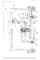
レーザ溶接は、例えば、図5、図6に示すようなレーザ溶接設備を用いて行う。このレーザ溶接設備は図6(a)(b)に示すように、溶接作業部11と、この溶接作業部11から左右に延びるレール12上を走行する左右の治具台車13、14とを備え、左右の治具台車13、14は車体の側、屋根、妻などの構体などを構成する外板3を支持して溶接作業部11へ交互に進入し、支持している外板3をそれに縦横に配する骨1、2とのレーザ溶接に供することを繰り返し、溶接作業部11から出る都度溶接によって製作した構体を取外して新たな外板3と交換する。溶接作業部11はレール15上を走行する門型の作業脚16を有している。この作業脚16は例えば5関節程度の多関節ロボット17を支持しており、溶接作業部11に進入した治具台車13上の外板3に縦横に配する骨1、2をレーザ溶接する。このレーザ溶接のために多関節ロボット17は図5に示すようにロボットアームの先端にレーザトーチ18を有し、このレーザトーチ18によって冷却機構付きのレーザ発振装置19から光ファイバを通じてレーザを供給され溶接部にレーザ照射して所定のレーザ溶接を行う。このレーザ溶接のために溶接作業部11は、その左右2箇所に加圧機構21を有し、溶接作業部11に進入してきた治具台車13、14上の外板およびそれに縦横に配する骨1、2を上方から所定位置に加圧支持し、レーザ溶接に備えるようにしている。加圧機構21はレール22上を走行する門型の支持脚23に加圧ロッド24を左右に2本ずつ支持しており、これら左右2本ずつの
加圧ロッド24によって前記加圧支持を行う。これらレーザ溶接作業はロボット系制御装置31と治具系制御装置32との協働した動作制御を伴って行われる。
Laser welding is performed using, for example, laser welding equipment as shown in FIGS. As shown in FIGS. 6 (a) and 6 (b), the laser welding equipment includes a
上記のような外板3と縦横に配する骨1、2との溶接接合を車体の側構体に適用した具体例を図3、図4に示している。図3、図4に示す側構体41は出入り口42の開口の間に窓43の開口を1つ設けるタイプのものであり、前記他方の骨1は、窓43および出入り口42の開口に沿って配した縦骨としてあり、その側面に端部2aが対向する前記一方の骨2は出入り口42の開口と出入り口42の開口との間に配した横骨、および出入り口42の開口と窓43の開口との間に配した横骨としている。
3 and 4 show specific examples in which the welded joint between the
鉄道車両では図3に示す側構体41で見られるように、その長手方向に長尺の横骨2を通して外板3を補強することが広く採用され、窓43や出入り口42の開口に沿う縦骨1の側部に端部2aが対向する本数が多く,それらの間の継手強度や外板3への接合強度が問題になりやすいところ、それら継手強度や接合強度を高めるのに図3、図4に示す具体例は有効である。しかも、図4に示すように窓43および出入り口42の開口に沿って連続するレーザ溶接接合部4はそれら開口からの雨水などの侵入に対する防水となるので好適である。
In railcars, as seen in the
また、図3、図4に示す例では、窓43や出入り口42の開口に沿う縦骨1はいずれもハット型断面のものとし、図4に示すように窓43や出入り口42の開口に設ける開口枠ないしは開口枠材42a、43aと別体としてあるが、これを一体に形成した共用部材とする簡略構造にても、前記継手強度や接合強度の向上が図れる。
In the example shown in FIGS. 3 and 4, the
特に、横向きの骨2は外板3の窓43および出入り口42の開口を除いた部分の内面に通して上下にほぼ等間隔に配列し、縦向きの骨1は外板3の窓43および出入り口42の開口およびの側部、外板3の端部(図示せず)に沿って配し、縦向きの骨1間では横向きの骨2に縦向きの補強材46を内側から渡して当てがい栓溶接、スポット溶接、レーザ溶接のいずれかの溶接接合部47で接合している。これにより、横向きの骨2を通せる面域には縦向きの骨1に優先して多く配列し、縦向きの骨1による横向きの骨2に対する分断を回避してレーザ溶接の連続性を確保しながら、極端に少なくなる縦向きの骨1と、縦向きの骨1間で横向きの骨2に縦向きに渡して外板3や外観に影響なく種々な溶接により溶接接合した補強材46とで必要な構体強度を確保できる。特に、補強材は外板との溶接がない上、接触もせず浮いた状態で、外板の面内せん断力による面外変形に対する強度を高められる。それには、図示しているように横向きの骨2はハット型断面を有してその両側のフランジ2bが外板3に溶接接合され、縦向きの補強材46はハット型の断面を有して横向きの骨2のフランジ2bより背部に嵌り合う切り欠き46bを有して横向きの骨2のフランジ2bに自身のフランジ46aを当ってそのフランジ2bに溶接接合されている構成が好適である。
In particular, the
本発明は鉄道車両の構体骨構造に実用でき、作業面、コスト面、強度面等に有利となる。 INDUSTRIAL APPLICABILITY The present invention can be practically used for the structure of a railway vehicle and is advantageous in terms of work, cost, strength, and the like.
1、2 骨
2a 端部
1b、2b フランジ
3 外板
4、5、6 溶接部
41 側構体
42 出入り口
43 窓
42a、43a 開口枠ないしは開口枠材
1, 2
Claims (4)
外板に溶接接合した一方の骨の端部および外板に跨って他方の骨を当てがい、それらの双方に他方の骨を溶接接合したことを特徴とする鉄道車両の構体骨構造。 In the structure bone structure of a railway vehicle in which one end of the bone arranged vertically and horizontally has a relationship facing the other side surface and is welded to the outer plate,
A structure bone structure of a railway vehicle, characterized in that an end of one bone welded to the outer plate and the other bone are applied across the outer plate, and the other bone is welded to both of them.
Priority Applications (1)
| Application Number | Priority Date | Filing Date | Title |
|---|---|---|---|
| JP2005171261A JP2006341813A (en) | 2005-06-10 | 2005-06-10 | Vehicle body bone structure for railway vehicle |
Applications Claiming Priority (1)
| Application Number | Priority Date | Filing Date | Title |
|---|---|---|---|
| JP2005171261A JP2006341813A (en) | 2005-06-10 | 2005-06-10 | Vehicle body bone structure for railway vehicle |
Publications (2)
| Publication Number | Publication Date |
|---|---|
| JP2006341813A true JP2006341813A (en) | 2006-12-21 |
| JP2006341813A5 JP2006341813A5 (en) | 2008-07-24 |
Family
ID=37639082
Family Applications (1)
| Application Number | Title | Priority Date | Filing Date |
|---|---|---|---|
| JP2005171261A Pending JP2006341813A (en) | 2005-06-10 | 2005-06-10 | Vehicle body bone structure for railway vehicle |
Country Status (1)
| Country | Link |
|---|---|
| JP (1) | JP2006341813A (en) |
Cited By (10)
| Publication number | Priority date | Publication date | Assignee | Title |
|---|---|---|---|---|
| JP2007112343A (en) * | 2005-10-21 | 2007-05-10 | Kawasaki Heavy Ind Ltd | Structure for railroad car |
| JP2008126757A (en) * | 2006-11-17 | 2008-06-05 | Tokyu Car Corp | Structure of railway rolling stock |
| WO2008068796A1 (en) * | 2006-11-30 | 2008-06-12 | The Kinki Sharyo Co., Ltd. | Body skeleton structure of rolling stock |
| JP2010167862A (en) * | 2009-01-21 | 2010-08-05 | Tokyu Car Corp | Vehicle panel structure |
| KR100985165B1 (en) | 2007-01-10 | 2010-10-05 | 가부시키가이샤 히타치세이사쿠쇼 | Railway vehicle body structure |
| JP2011025785A (en) * | 2009-07-23 | 2011-02-10 | Tokyu Car Corp | Vehicle panel structure |
| JP2011073674A (en) * | 2010-12-29 | 2011-04-14 | Kawasaki Heavy Ind Ltd | Railroad vehicle structure |
| JP2016107888A (en) * | 2014-12-08 | 2016-06-20 | 川崎重工業株式会社 | Side body structure for railway vehicle |
| JP2016107889A (en) * | 2014-12-08 | 2016-06-20 | 川崎重工業株式会社 | Bone structure of railway vehicle, bone structure assembly and side body structure |
| CN113369675A (en) * | 2021-07-12 | 2021-09-10 | 中车唐山机车车辆有限公司 | Carriage processing method, carriage and vehicle |
Citations (1)
| Publication number | Priority date | Publication date | Assignee | Title |
|---|---|---|---|---|
| JP2006027366A (en) * | 2004-07-13 | 2006-02-02 | Kawasaki Heavy Ind Ltd | Structure for railroad car |
-
2005
- 2005-06-10 JP JP2005171261A patent/JP2006341813A/en active Pending
Patent Citations (1)
| Publication number | Priority date | Publication date | Assignee | Title |
|---|---|---|---|---|
| JP2006027366A (en) * | 2004-07-13 | 2006-02-02 | Kawasaki Heavy Ind Ltd | Structure for railroad car |
Cited By (11)
| Publication number | Priority date | Publication date | Assignee | Title |
|---|---|---|---|---|
| JP2007112343A (en) * | 2005-10-21 | 2007-05-10 | Kawasaki Heavy Ind Ltd | Structure for railroad car |
| JP2008126757A (en) * | 2006-11-17 | 2008-06-05 | Tokyu Car Corp | Structure of railway rolling stock |
| WO2008068796A1 (en) * | 2006-11-30 | 2008-06-12 | The Kinki Sharyo Co., Ltd. | Body skeleton structure of rolling stock |
| US8240255B2 (en) | 2006-11-30 | 2012-08-14 | The Kinki Sharyo Co., Ltd. | Body frame structure of railway vehicle |
| KR100985165B1 (en) | 2007-01-10 | 2010-10-05 | 가부시키가이샤 히타치세이사쿠쇼 | Railway vehicle body structure |
| JP2010167862A (en) * | 2009-01-21 | 2010-08-05 | Tokyu Car Corp | Vehicle panel structure |
| JP2011025785A (en) * | 2009-07-23 | 2011-02-10 | Tokyu Car Corp | Vehicle panel structure |
| JP2011073674A (en) * | 2010-12-29 | 2011-04-14 | Kawasaki Heavy Ind Ltd | Railroad vehicle structure |
| JP2016107888A (en) * | 2014-12-08 | 2016-06-20 | 川崎重工業株式会社 | Side body structure for railway vehicle |
| JP2016107889A (en) * | 2014-12-08 | 2016-06-20 | 川崎重工業株式会社 | Bone structure of railway vehicle, bone structure assembly and side body structure |
| CN113369675A (en) * | 2021-07-12 | 2021-09-10 | 中车唐山机车车辆有限公司 | Carriage processing method, carriage and vehicle |
Similar Documents
| Publication | Publication Date | Title |
|---|---|---|
| JP2006341813A (en) | Vehicle body bone structure for railway vehicle | |
| WO2008068796A1 (en) | Body skeleton structure of rolling stock | |
| JP4705413B2 (en) | Welding and joining method of railcar outer plate and accessory and its side structure | |
| JP5038123B2 (en) | Rolling laser welding method of railway vehicle structure, lap laser welding joint, railway vehicle structure | |
| US8689703B2 (en) | Method for weld-joining attachment to outer panel of railway vehicle and car body side structure produced by the same | |
| JP4280260B2 (en) | Railway vehicle and frame welding method | |
| JP2009241116A (en) | Welding method of metallic material and joined body of metallic material | |
| JP4804104B2 (en) | Railway vehicle side structure and manufacturing method thereof | |
| JP2006341300A5 (en) | ||
| JP2013018409A (en) | Door sash | |
| JP4280265B2 (en) | Railway vehicle | |
| KR910000456A (en) | Railroad car system and its manufacturing method | |
| KR20010021995A (en) | Side wall for railway car and corresponding railway car body | |
| JP2007045304A (en) | Railway vehicle structure and its manufacturing method | |
| JP2010013021A (en) | Front pillar for automobile | |
| JP2010158983A (en) | Vehicle body structure formed by laser welding and spot welding, and its manufacturing method | |
| JP4224502B2 (en) | Laser welding method and railway vehicle | |
| JP4478039B2 (en) | Railway vehicle structure | |
| JP4280261B2 (en) | Railway vehicle | |
| JP2008006472A5 (en) | ||
| JP2007125573A (en) | Workpiece joining method, joined body, and railroad vehicle | |
| CN110171484B (en) | Vehicle pillar structure and method for manufacturing vehicle pillar | |
| JP2010149849A (en) | Side body structure of railroad vehicle | |
| JP2007167924A (en) | Method for welding and joining body structural member of railroad vehicle, and joint structure used therefor | |
| JP2008207190A (en) | Joined joint and railroad car using the same |
Legal Events
| Date | Code | Title | Description |
|---|---|---|---|
| A521 | Written amendment |
Free format text: JAPANESE INTERMEDIATE CODE: A523 Effective date: 20080610 |
|
| A621 | Written request for application examination |
Free format text: JAPANESE INTERMEDIATE CODE: A621 Effective date: 20080610 |
|
| RD02 | Notification of acceptance of power of attorney |
Free format text: JAPANESE INTERMEDIATE CODE: A7422 Effective date: 20090526 |
|
| RD04 | Notification of resignation of power of attorney |
Free format text: JAPANESE INTERMEDIATE CODE: A7424 Effective date: 20091028 |
|
| A977 | Report on retrieval |
Free format text: JAPANESE INTERMEDIATE CODE: A971007 Effective date: 20100408 |
|
| A131 | Notification of reasons for refusal |
Free format text: JAPANESE INTERMEDIATE CODE: A131 Effective date: 20100420 |
|
| A521 | Written amendment |
Free format text: JAPANESE INTERMEDIATE CODE: A523 Effective date: 20100616 |
|
| A02 | Decision of refusal |
Free format text: JAPANESE INTERMEDIATE CODE: A02 Effective date: 20101102 |