JP2006324345A - Cooler of electronic heating element - Google Patents
Cooler of electronic heating element Download PDFInfo
- Publication number
- JP2006324345A JP2006324345A JP2005144408A JP2005144408A JP2006324345A JP 2006324345 A JP2006324345 A JP 2006324345A JP 2005144408 A JP2005144408 A JP 2005144408A JP 2005144408 A JP2005144408 A JP 2005144408A JP 2006324345 A JP2006324345 A JP 2006324345A
- Authority
- JP
- Japan
- Prior art keywords
- cooling
- heating element
- electronic heating
- heat
- heat sink
- Prior art date
- Legal status (The legal status is an assumption and is not a legal conclusion. Google has not performed a legal analysis and makes no representation as to the accuracy of the status listed.)
- Granted
Links
- 238000010438 heat treatment Methods 0.000 title claims abstract description 120
- 238000001816 cooling Methods 0.000 claims abstract description 208
- 239000000110 cooling liquid Substances 0.000 claims abstract description 28
- 230000002093 peripheral effect Effects 0.000 claims description 8
- XLYOFNOQVPJJNP-UHFFFAOYSA-N water Substances O XLYOFNOQVPJJNP-UHFFFAOYSA-N 0.000 claims description 8
- 229910001868 water Inorganic materials 0.000 claims description 8
- 230000000295 complement effect Effects 0.000 claims description 6
- 239000003507 refrigerant Substances 0.000 claims description 5
- 229910001285 shape-memory alloy Inorganic materials 0.000 claims description 3
- 230000001747 exhibiting effect Effects 0.000 abstract description 3
- 239000002826 coolant Substances 0.000 description 25
- 230000005855 radiation Effects 0.000 description 11
- 239000004020 conductor Substances 0.000 description 10
- 239000007788 liquid Substances 0.000 description 9
- 239000012530 fluid Substances 0.000 description 7
- 238000004891 communication Methods 0.000 description 4
- 238000001704 evaporation Methods 0.000 description 4
- 230000020169 heat generation Effects 0.000 description 4
- 238000004804 winding Methods 0.000 description 4
- 230000006870 function Effects 0.000 description 3
- 230000017525 heat dissipation Effects 0.000 description 3
- 229910052751 metal Inorganic materials 0.000 description 3
- 239000002184 metal Substances 0.000 description 3
- 238000000034 method Methods 0.000 description 3
- 229910000925 Cd alloy Inorganic materials 0.000 description 2
- RYGMFSIKBFXOCR-UHFFFAOYSA-N Copper Chemical compound [Cu] RYGMFSIKBFXOCR-UHFFFAOYSA-N 0.000 description 2
- XUIMIQQOPSSXEZ-UHFFFAOYSA-N Silicon Chemical compound [Si] XUIMIQQOPSSXEZ-UHFFFAOYSA-N 0.000 description 2
- 229910045601 alloy Inorganic materials 0.000 description 2
- 239000000956 alloy Substances 0.000 description 2
- 238000005452 bending Methods 0.000 description 2
- 229910052802 copper Inorganic materials 0.000 description 2
- 239000010949 copper Substances 0.000 description 2
- 229920001971 elastomer Polymers 0.000 description 2
- 230000008020 evaporation Effects 0.000 description 2
- 239000007789 gas Substances 0.000 description 2
- PCHJSUWPFVWCPO-UHFFFAOYSA-N gold Chemical compound [Au] PCHJSUWPFVWCPO-UHFFFAOYSA-N 0.000 description 2
- 239000010931 gold Substances 0.000 description 2
- 229910052737 gold Inorganic materials 0.000 description 2
- 239000004519 grease Substances 0.000 description 2
- 238000003825 pressing Methods 0.000 description 2
- 230000009467 reduction Effects 0.000 description 2
- 229910052710 silicon Inorganic materials 0.000 description 2
- 239000010703 silicon Substances 0.000 description 2
- 229920002595 Dielectric elastomer Polymers 0.000 description 1
- YCKRFDGAMUMZLT-UHFFFAOYSA-N Fluorine atom Chemical compound [F] YCKRFDGAMUMZLT-UHFFFAOYSA-N 0.000 description 1
- DGAQECJNVWCQMB-PUAWFVPOSA-M Ilexoside XXIX Chemical compound C[C@@H]1CC[C@@]2(CC[C@@]3(C(=CC[C@H]4[C@]3(CC[C@@H]5[C@@]4(CC[C@@H](C5(C)C)OS(=O)(=O)[O-])C)C)[C@@H]2[C@]1(C)O)C)C(=O)O[C@H]6[C@@H]([C@H]([C@@H]([C@H](O6)CO)O)O)O.[Na+] DGAQECJNVWCQMB-PUAWFVPOSA-M 0.000 description 1
- 230000005679 Peltier effect Effects 0.000 description 1
- ZLMJMSJWJFRBEC-UHFFFAOYSA-N Potassium Chemical compound [K] ZLMJMSJWJFRBEC-UHFFFAOYSA-N 0.000 description 1
- 229910000831 Steel Inorganic materials 0.000 description 1
- 229910004337 Ti-Ni Inorganic materials 0.000 description 1
- 229910010380 TiNi Inorganic materials 0.000 description 1
- 229910011209 Ti—Ni Inorganic materials 0.000 description 1
- 229910001297 Zn alloy Inorganic materials 0.000 description 1
- 230000009471 action Effects 0.000 description 1
- 239000000853 adhesive Substances 0.000 description 1
- 230000001070 adhesive effect Effects 0.000 description 1
- 229910052782 aluminium Inorganic materials 0.000 description 1
- XAGFODPZIPBFFR-UHFFFAOYSA-N aluminium Chemical compound [Al] XAGFODPZIPBFFR-UHFFFAOYSA-N 0.000 description 1
- 238000005219 brazing Methods 0.000 description 1
- 230000008859 change Effects 0.000 description 1
- KYKAJFCTULSVSH-UHFFFAOYSA-N chloro(fluoro)methane Chemical compound F[C]Cl KYKAJFCTULSVSH-UHFFFAOYSA-N 0.000 description 1
- 239000000112 cooling gas Substances 0.000 description 1
- 239000000498 cooling water Substances 0.000 description 1
- 230000005489 elastic deformation Effects 0.000 description 1
- 239000007772 electrode material Substances 0.000 description 1
- 229910052731 fluorine Inorganic materials 0.000 description 1
- 239000011737 fluorine Substances 0.000 description 1
- KHYBPSFKEHXSLX-UHFFFAOYSA-N iminotitanium Chemical compound [Ti]=N KHYBPSFKEHXSLX-UHFFFAOYSA-N 0.000 description 1
- 230000006872 improvement Effects 0.000 description 1
- 239000000463 material Substances 0.000 description 1
- 210000003205 muscle Anatomy 0.000 description 1
- 239000003921 oil Substances 0.000 description 1
- 238000012856 packing Methods 0.000 description 1
- RVZRBWKZFJCCIB-UHFFFAOYSA-N perfluorotributylamine Chemical compound FC(F)(F)C(F)(F)C(F)(F)C(F)(F)N(C(F)(F)C(F)(F)C(F)(F)C(F)(F)F)C(F)(F)C(F)(F)C(F)(F)C(F)(F)F RVZRBWKZFJCCIB-UHFFFAOYSA-N 0.000 description 1
- 239000012466 permeate Substances 0.000 description 1
- 239000004033 plastic Substances 0.000 description 1
- 238000007747 plating Methods 0.000 description 1
- 229910021420 polycrystalline silicon Inorganic materials 0.000 description 1
- 229910052700 potassium Inorganic materials 0.000 description 1
- 239000011591 potassium Substances 0.000 description 1
- 239000011347 resin Substances 0.000 description 1
- 229920005989 resin Polymers 0.000 description 1
- 229910052708 sodium Inorganic materials 0.000 description 1
- 239000011734 sodium Substances 0.000 description 1
- 239000010959 steel Substances 0.000 description 1
- 239000010409 thin film Substances 0.000 description 1
Images
Landscapes
- Cooling Or The Like Of Semiconductors Or Solid State Devices (AREA)
Abstract
Description
本発明は、CPUやMPUなどの電子発熱体を冷却する装置に係わり、特に小型で放熱性、静音性に優れた電子発熱体の冷却装置に関する。 The present invention relates to a device for cooling an electronic heating element such as a CPU or MPU, and more particularly to a cooling device for an electronic heating element that is small in size and excellent in heat dissipation and quietness.
近年、コンピュータ(以下「PC」という。)全体の発熱量(消費電力)は年々増加の一途をたどってきており、PCを構成する様々なパーツの中でも、とりわけ発熱量の大きいのがCPUやMPUなど(以下「電子発熱体」という。)である。特に、CPUのTDP(熱設計電力)は100Wを超えるものもあり、最大のものに至っては115W(Pentium4(登録商標)の600シリーズなど)もある。 In recent years, the amount of heat generation (power consumption) of the entire computer (hereinafter referred to as “PC”) has been increasing year by year, and among the various parts constituting the PC, the heat generation amount is particularly large among CPUs and MPUs. (Hereinafter referred to as “electronic heating element”). In particular, some CPUs have a TDP (thermal design power) exceeding 100 W, and the maximum one is 115 W (such as Pentium 4 (registered trademark) 600 series).
このような電子発熱体を冷却する装置としては、空冷式の冷却装置と水冷式の冷却装置が一般的である。 As a device for cooling such an electronic heating element, an air cooling type cooling device and a water cooling type cooling device are generally used.
前記空冷式の冷却装置は、電子発熱体の表面(放熱面)にヒートシンクの接触面が熱伝導シート又はシリコングリスなどからなる熱伝導体を介して接合されており、前記ヒートシンクの放熱フィンに対してファンから空気を送ることにより前記電子発熱体の冷却を行うものである。 In the air-cooling type cooling device, the contact surface of the heat sink is joined to the surface (heat radiation surface) of the electronic heating element via a heat conductor made of a heat conductive sheet or silicon grease, Then, the electronic heating element is cooled by sending air from the fan.
また水冷式の冷却装置は、電子発熱体の表面(放熱面)に冷却液が流通する水冷ジャケット(水冷ヘッド)を固定するとともに、外部に設けられたラジエータの出入口と前記冷却ヘッドの出入口との間にはチューブなどを用いて形成した循環流路が設けられている。また前記ラジエータと前記水冷ジャケットとの間にはポンプが設けられており、前記ポンプを駆動すると冷却液が前記チューブを通じて前記ラジエータと前記冷却ヘッドとの間で循環する。このため、電子発熱体が発した熱は、媒体である冷却液と一緒に前記チューブを通じて冷却ヘッドの外部に運び出される。このとき暖められた冷却液が、前記ラジエータで冷却された後、再び前記冷却ヘッド(電子発熱体)側に戻すことにより、前記電子発熱体を冷却する仕組みである。 The water-cooling type cooling device fixes a water-cooling jacket (water-cooling head) through which the coolant flows on the surface (heat radiation surface) of the electronic heating element, and also includes an outlet / inlet of the radiator provided outside and the inlet / outlet of the cooling head. A circulation channel formed using a tube or the like is provided between them. A pump is provided between the radiator and the water cooling jacket, and when the pump is driven, a coolant circulates between the radiator and the cooling head through the tube. For this reason, the heat generated by the electronic heating element is carried out of the cooling head through the tube together with the cooling liquid as a medium. The cooling liquid warmed at this time is cooled by the radiator and then returned to the cooling head (electronic heating element) side to cool the electronic heating element.
なお、その他の冷却装置としては、例えば冷却ガスやペルチェ効果を利用したものなども存在している。 As other cooling devices, for example, those using a cooling gas or the Peltier effect exist.
上記技術に関する先行技術文献としては、例えば特許文献1および2などが存在している。
上記空冷式の冷却装置および水冷式の冷却装置はともに冷却能力が高いことが知られているが、電子発熱体の発熱量の増大に伴い、今後さらなる冷却能力の向上が求められる。 Both the air-cooling type cooling device and the water-cooling type cooling device are known to have a high cooling capacity. However, as the heat generation amount of the electronic heating element increases, further improvement of the cooling capacity is required in the future.
しかし、前記空冷式の冷却装置のヒートシンク及び前記水冷式の冷却装置の冷却ジャケットは、ともに電子発熱体の表面(放熱面)だけに当接する構成であるため、前記電子発熱体の一面からしか熱を奪うことができず、冷却効率を高めるには限界がある。 However, since the heat sink of the air-cooled cooling device and the cooling jacket of the water-cooled cooling device are both in contact with only the surface (heat radiating surface) of the electronic heating element, heat is generated only from one surface of the electronic heating element. There is a limit to improving the cooling efficiency.
この点、前記空冷式の冷却装置ではヒートシンクに当たる空気の流量を増加させることにより、前記水冷式の冷却装置ではラジエータに当たる空気の流量を増加させることにより、冷却効率を高めることが可能となる。 In this regard, it is possible to increase the cooling efficiency by increasing the flow rate of air that hits the heat sink in the air-cooled cooling device, and by increasing the flow rate of air that hits the radiator in the water-cooled cooling device.
しかし、そのためにはファンの回転数を高めるか、または大きな口径を有するファンを採用する必要があるところ、前者の方法では回転時におけるファンの動作音(風切り音や回転音)が大きく無音化又は静音化に適さないという問題がある。一方、後者の方法ではPC全体を小型化し難いという問題がある。 However, for that purpose, it is necessary to increase the number of rotations of the fan or to employ a fan having a large aperture. However, in the former method, the operation sound (wind noise or rotation sound) of the fan during rotation is greatly reduced or silenced. There is a problem that it is not suitable for noise reduction. On the other hand, the latter method has a problem that it is difficult to downsize the entire PC.
本発明は上記従来の課題を解決するためのものであり、単体で又は従来の冷却方式と組み合わせることにより、冷却能力に優れた電子発熱体の冷却装置を提供することを目的としている。 The present invention has been made to solve the above-described conventional problems, and an object of the present invention is to provide a cooling device for an electronic heating element having excellent cooling capacity by itself or in combination with a conventional cooling method.
また本発明は、小型で放熱性、静音性に優れた電子発熱体の冷却装置を提供することを目的としている。 Another object of the present invention is to provide a cooling device for an electronic heating element that is small in size and excellent in heat dissipation and quietness.
本発明は、ソケット内に保持された電子発熱体を冷却する装置であって、前記ソケットが、前記電子発熱体が装着されるハウジングと、前記電子発熱体を前記ハウジング内に保持する蓋体とを有しており、前記ハウジングと前記蓋体の少なくとも一方に前記電子発熱体を冷媒を用いて冷やす冷却手段が設けられていることを特徴とするものである。 The present invention is an apparatus for cooling an electronic heating element held in a socket, wherein the socket includes a housing to which the electronic heating element is mounted, and a lid for holding the electronic heating element in the housing. And at least one of the housing and the lid is provided with cooling means for cooling the electronic heating element using a refrigerant.
本発明の電子発熱体の冷却装置では、CPUなどの電子発熱体が発した熱を、前記電子発熱体を直接に又は前記電子発熱体を保持するソケットを介して奪うことができるため、前記電子発熱体をより効率良く冷却することができる。このため、従来の冷却装置と組み合わせると、より冷却能力に優れた電子発熱体の冷却装置とすることができる。よって、従来の冷却装置のファンの回転数を低めに設定することが可能となるため、PCの静音性を高めることができる。 In the cooling device for an electronic heating element of the present invention, the heat generated by the electronic heating element such as a CPU can be taken away directly or via a socket holding the electronic heating element. The heating element can be cooled more efficiently. For this reason, when combined with a conventional cooling device, it is possible to provide a cooling device for an electronic heating element that is more excellent in cooling capacity. Therefore, since it becomes possible to set the rotation speed of the fan of the conventional cooling device low, the quietness of PC can be improved.
また冷却管がソケットに一体化された状態で設けられているため、従来のように別体に形成された水冷ジャケットを電子発熱体に固定する必要がないため、小型の冷却装置を提供することができる。 In addition, since the cooling pipe is provided in an integrated state with the socket, it is not necessary to fix the water cooling jacket formed separately to the electronic heating element as in the prior art, and a small cooling device is provided. Can do.
例えば、前記冷却手段が、複数のフィンを有するとともに前記蓋体の表面に設けられたヒートシンクと、前記フィンの間に蛇行状に配管された冷却管と、前記冷却管内を流れる冷却液と、前記冷却液を循環させるポンプと、を有するものとして構成される。 For example, the cooling means has a plurality of fins and a heat sink provided on the surface of the lid, a cooling pipe piped in a meandering manner between the fins, a coolant flowing in the cooling pipe, And a pump for circulating the coolant.
また前記冷却手段が、ハウジング内に前記電子発熱体の周囲を取り囲むように周設された溝と、前記溝内に配管された冷却管と、前記冷却管内を流れる冷却液と、前記冷却液を循環させるポンプと、を有するものとして構成される。 The cooling means includes a groove provided in the housing so as to surround the periphery of the electronic heating element, a cooling pipe provided in the groove, a cooling liquid flowing in the cooling pipe, and the cooling liquid. And a pump to be circulated.
さらには前記冷却手段が、前記ハウジングに設けられた注入口及び排水口と、前記ハウジングの外部において前記注入口と前記排水口との間に設けられた冷却管と、前記注入口から注水され且つ前記排水口から排出させられる冷却液と、前記冷却液を循環させるポンプと、を有するものとして構成される。 Further, the cooling means includes an inlet and a drain provided in the housing, a cooling pipe provided between the inlet and the drain outside the housing, and water is poured from the inlet. It is configured to have a coolant discharged from the drain and a pump for circulating the coolant.
あるいは、前記冷却手段が、前記電子発熱体が発する熱の表面温度分布に応じて高温部となる位置に対向して設置された第1のヒートシンクと、前記高温部以外の低温部の位置に対向して設置された第2のヒートシンクと、前記第1のヒートシンクと第2のヒートシンクとの間に配管された冷却管と、前記冷却管の両端に設けられた一対のポンプと、前記一対のポンプを相補的に駆動するドライバ手段と、を有するものとして構成される。 Alternatively, the cooling means faces the position of the first heat sink disposed opposite to the position that becomes the high temperature portion according to the surface temperature distribution of the heat generated by the electronic heating element, and the position of the low temperature portion other than the high temperature portion. A second heat sink, a cooling pipe piped between the first heat sink and the second heat sink, a pair of pumps provided at both ends of the cooling pipe, and the pair of pumps And a driver means for driving in a complementary manner.
また前記冷却手段が、前記電子発熱体が発する熱の表面温度分布に応じて中央部に形成された高温部と、その周辺部に形成された低温部との間に平面スター状に配管された冷却管と、前記冷却管両端に設けられた一対のポンプと、前記一対のポンプを相補的に駆動するドライバ手段と、を有するものとして構成される。 Further, the cooling means is piped in a planar star shape between a high temperature portion formed in the central portion according to a surface temperature distribution of heat generated by the electron heating element and a low temperature portion formed in the peripheral portion thereof. A cooling pipe, a pair of pumps provided at both ends of the cooling pipe, and driver means for driving the pair of pumps in a complementary manner are configured.
また前記冷却手段が、前記蓋体の表面に設けられた複数のヒートパイプであるものとして構成される。 Further, the cooling means is configured as a plurality of heat pipes provided on the surface of the lid.
上記において、前記ヒートシンクは、前記電子発熱体の表面に又は蓋体の表面に固定されているものが好ましい。 In the above, the heat sink is preferably fixed to the surface of the electronic heating element or the surface of the lid.
また冷却能力を高めるためには、空冷用のファンが設けられていることが好ましく、さらには前記冷却液が循環する経路内に、前記冷却液を冷却するラジエータが設けられているものが好ましい。 In order to increase the cooling capacity, it is preferable that an air cooling fan is provided, and it is more preferable that a radiator for cooling the cooling liquid is provided in a path through which the cooling liquid circulates.
また、前記冷却液が、正逆の双方向に移動させられることを特徴とするものである。
上記において、前記ヒートシンクが形状記憶合金で形成されるものとすることができる。
Further, the coolant is moved in both forward and reverse directions.
In the above, the heat sink may be formed of a shape memory alloy.
本発明では、単体としての冷却性能に優れた電子発熱体の冷却装置を提供することができる。 The present invention can provide a cooling device for an electronic heating element having excellent cooling performance as a single unit.
しかも従来の冷却装置と組み合わせたときには、ファンの風量を上げる必要がなくなるため、このような電子発熱体の冷却装置が搭載されたPCの静音化に寄与することが可能となる。 In addition, when combined with a conventional cooling device, it is not necessary to increase the air flow rate of the fan, so that it is possible to contribute to the noise reduction of the PC on which such a cooling device for an electronic heating element is mounted.
また冷却管がソケットに一体化されているため、従来のように別体に形成された水冷ジャケットを電子発熱体に固定する必要がない。さらには大きな口径を有するファンを採用する必要がなくなるため、PC全体の小型化にも貢献することができる。 Further, since the cooling pipe is integrated with the socket, it is not necessary to fix the water cooling jacket formed separately as in the conventional case to the electronic heating element. Furthermore, since it is not necessary to employ a fan having a large aperture, it is possible to contribute to downsizing of the entire PC.
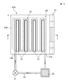
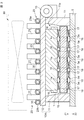
図1は本発明の第1の実施の形態としての電子発熱体の冷却装置を示す平面図、図2は図1の2−2線における断面図である。 FIG. 1 is a plan view showing a cooling device for an electronic heating element as a first embodiment of the present invention, and FIG. 2 is a cross-sectional view taken along line 2-2 of FIG.
図1及び図2に示すように、第1の実施の形態に示す冷却装置はCPUなどの電子発熱体1を保持するソケット10Aを有している。前記ソケット10Aは、枠状のハウジング11とこのハウジング11の一端に設けられたヒンジ部13を支点として回動自在に支持された蓋体12とを有している。
As shown in FIGS. 1 and 2, the cooling device shown in the first embodiment includes a
図2に示すように、前記ハウジング11はマザーボード5上の所定の位置に固定されている。前記ハウジング11の内部には凹部11aが形成されており、この凹部11aにはインターポーザ15が設けられている。前記インターポーザ15の上下両面には複数の弾性接点16,17が設けられている。インターポーザ15の上部側の個々の弾性接点16と下部側の個々の弾性接点17とはインターポーザ15の板厚内に埋設された複数の導電体18を介してそれぞれ導通接続されている。そして、下部側の弾性接点17は前記マザーボード5上に形成されている複数の対向電極5aに接する状態で載置されている。
As shown in FIG. 2, the
前記弾性接点16,17としては、例えば導通変形部が周縁部から中心に向かって渦巻き形状に立ち上がるスパイラル接触子、異なる内部応力を付与することによって弾性変形部に撓みを発生させたストレスドメタル、特開2004−186026や特開2004−281161などに開示されている粘着式コネクタなどを用いることができる。
Examples of the
前記ハウジング11の上面にはヒートシンク20が設けられている。前記ヒートシンク20は、熱伝導率の高いアルミニウムなどで形成されており、その上部には互いに平行に配置された複数の放熱フィン21,21,・・・・が突出形成されている。
A
図2に示すように、前記ヒートシンク20は放熱フィン21が前記蓋体12に一体的に形成されたものであってもよいし、別体に形成されたものであってもよい。前記放熱フィン21が、前記蓋体12に一体化された前記ヒートシンク20の場合には、前記蓋体12の下面と前記電子発熱体1の表面側に設けられた金属製のカバーの上面(放熱面)(以下、「電子発熱体1の表面」という。)とが接合される。また前記ヒートシンク20が前記蓋体12とは別体のものにあっては、前記ヒートシンクの底面(接触面)と前記電子発熱体1の表面とが蓋体12に形成された開口(図3参照)を通じて接合される。いずれの場合にあっても、前記ヒートシンク20の下面と前記電子発熱体1の表面とは熱伝導シート又はシリコングリスなどからなる熱伝導体(図示せず)を介して接合される構成が好ましい。
As shown in FIG. 2, the
前記ヒートシンク20を形成する放熱フィン21の幅方向のピッチ寸法内には、銅などで形成され且つ1本の連続するパイプを複数回折り曲げて形成した蛇行状(ミアンダー(meander)状ともいう。)の冷却管23が、例えば蝋付けされるなどして固定されている。前記冷却管23の蛇行状の部分が蛇行部23Aであり、冷却管23の一端23aと他端23bとの間には、例えばポンプ31、ラジエータ32などが設けられており、前記冷却管23とともに一つの循環流路が形成されている。
Within the pitch dimension in the width direction of the
前記電子発熱体1は、前記蓋体12を開口させた状態において前記ハウジング11の凹部11a内に装着される。次に、前記蓋体12を閉鎖方向に回動させて閉塞させるとともに後述の図3に示すようなロック手段を用いてハウジング11と前記蓋体12とがロックされ、前記電子発熱体1がハウジング11と前記蓋体12との間に保持される。
The
このとき、前記蓋体12の表面と電子発熱体1の表面とが熱伝導体を介して密着させられる。同時に、前記電子発熱体1が前記蓋体12により図示Z2方向の加圧させられるため、前記弾性接点16,17がわずかにZ方向に弾性変形させられる。これにより、前記電子発熱体1の下面に設けられた複数の外部接続電極(LGA)1aと前記マザーボード5上に形成された複数の対向電極5aとが前記インターポーザ15の前記弾性接点16,17を介してそれぞれ導通接続される。
At this time, the surface of the
前記冷却管23の中には冷却液35が注入されている。そして、前記ポンプ31を始動させることにより、前記冷却液35が冷却管23内を循環する。前記冷却液35は冷却管23の蛇行部23Aを通過するときに、電子発熱体1が発した熱を奪う。そして、このとき暖められた前記冷却液35は前記ラジエータ32において冷却されて、再びヒートシンク20上の蛇行部23Aに戻される。このため、前記冷却液35を媒体としてヒートシンク20とラジエータ32との間で熱交換させることができるため、ヒートシンク20のみの場合に比較して冷却能力を高めることが可能である。
A cooling
なお、さらに前記電子発熱体1を冷却したい場合には、図2に点線で示すように、前記ヒートシンク20の上部にファン39を設けることにより、前記ヒートシンク20を直接空冷してもよい。ヒートシンク20の上部にファン39を設けて空冷する冷却装置は従来から存在するが、本発明の第1の実施の形態に示す冷却装置では、これに加えて冷却管23を用いてヒートシンク20を強制的に水冷する構成であるため、さらに冷却能力を高めることが可能である。
If it is desired to further cool the
次に本発明の第2の実施の形態について説明する。
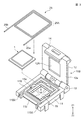
図3は本発明の第2の実施の形態としての電子発熱体の冷却装置を構成するソケットを示す斜視図である。
Next, a second embodiment of the present invention will be described.
FIG. 3 is a perspective view showing a socket constituting a cooling device for an electronic heating element according to a second embodiment of the present invention.
図3に示すソケット10Bは、上記第1の実施の形態に示したソケット10Aとほぼ同様の構成であり、マザーボード側に固定されるハウジング11と、ヒンジ部13で回動自在に設けられた蓋体12を有している。また前記蓋体12の中央には、開口部12Aが形成されている。電子発熱体1の表面は前記開口部12Aを介してソケット10Bの外部に露出されるようになっており、この開口部12Aを通じて電子発熱体1の表面とヒートシンクの接触面とを接合させることが可能である。
The
前記蓋体12の端部には掛止部14が形成されている。そして、前記掛止部14に対向するハウジング11の端部には、被掛止部11bが形成されている。前記掛止部14と被掛止部11bとがハウジング11と蓋体12と閉塞状態に固定するロック手段を形成している。
A hooking
ただし、第2の実施の形態に示す電子発熱体の冷却装置では、ソケット10Bを形成するハウジング11の外側部と凹部11aの間に、前記凹部11aの周囲を取り囲むように周設された溝11Bが形成されている点が異なっている。
However, in the cooling device for an electronic heating element shown in the second embodiment, a
前記溝11Bには前記ハウジング11の外部に連続する連通溝11B1,11B2が形成されている。前記溝11B、連通溝11B1,11B2の構内には、一本の細管を前記溝11Bの形状に合わせて複数回巻きいて略コイル状に形成さした冷却管25が設けられている。すなわち、冷却管25の巻き部25Aが溝11Bの内部に設けられ、前記冷却管25の一方の端部25aと他方の端部25bは前記連通溝11B1と連通溝11B2を介してそれぞれハウジング11の外部に延びている。なお、前記冷却管25は熱伝導率の高い銅管などが好ましいが、その他スチール管、樹脂性のチューブなどであってもよい。
In the
そして、前記冷却管25の一方の端部25aと他方の端部は25bとの間には、上記同様にポンプ、ラジエータなどが設けられており、前記冷却管25とともに一つの循環流路を形成している。
In addition, a pump, a radiator, and the like are provided between the one
前記ポンプを始動させて、冷却液35を前記冷却管25の巻き部25Aと前記ラジエータとの間で循環させると、電子発熱体1から発する熱を奪うことができる。特に、第2の実施の形態における冷却装置では、前記冷却管25の巻き部25Aが電子発熱体1の周囲を取り囲むように配置されているため、電子発熱体1から側面から発せられる熱を冷却することが可能である。
When the pump is started and the
このため、主として電子発熱体1の表面から発せられる熱については従来のヒートシンクおよびファンの組み合わせを用いて冷却し、これに加えて電子発熱体1の側面から発せられる熱については上記第2の実施の形態に示す冷却装置で冷却するようにすると、さらに冷却能力の高い冷却装置とすることができる。
For this reason, the heat generated mainly from the surface of the
次に本発明の第3の実施の形態について説明する。
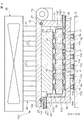
図4は本発明の第3の実施の形態としての電子発熱体の冷却装置を構成するソケットを示す図2同様の断面図である。
Next, a third embodiment of the present invention will be described.
FIG. 4 is a sectional view similar to FIG. 2 showing a socket constituting a cooling device for an electronic heating element as a third embodiment of the present invention.
図4に示すソケット10Cも上記第1及び第2の実施の形態に示したソケット10A,10Bとほぼ同様の構成であり、ヒンジ部13で回動自在に設けられた蓋体12の上部には、一体または別体に形成されたヒートシンク20が設けられており、さらに前記ヒートシンク20の上部にはファン39が取り付けられている。
The
ただし、第3の実施の形態に示すソケット10Cは、上記第1及び第2の実施の形態に示したソケット10A,10Bと以下の点で相違している。
However, the
すなわち、第3の実施の形態に示すハウジング11は底部11Aを有しており、この底部11Aには前記電子発熱体1の下面に設けられた複数の外部接続電極(LGA)1aと対向する複数のスルーホール11cが設けられている。前記スルーホール11cの上面には電極11dが形成され、下面には図示Z2方向に突出する凸状電極11eが形成されている。前記電極11dと前記凸状電極11eとは前記スルーホール11c内に設けられた導電体19を介して導通接続されている。
That is, the
前記スルーホール11cは直径1mm未満であり、前記導電体19、電極11dおよび凸状電極11eは金メッキなどで形成することができ、スルーホール11cの内部は前記金メッキされた導電体19で埋め尽くされている。このため、前記ハウジング11の凹部11aの内部と外部とは隔離されており、凹部11a内の液体がハウジング11の外部に液漏れし難くなっている。
The through
前記凹部11aを形成する4つの内壁の上面とこれに対向する前記蓋体12の下面には一対の対向溝11f,12aがそれぞれ周設されており、これら一対の対向溝11f,12aの構内には、ゴムなどで形成されたパッキン(またはOリング)27が設けられている。このため、前記蓋体12でハウジング11を閉塞するとともにロック手段でロック状態にすると、凹部11a内を密閉することが可能とされている。
A pair of opposing
また前記凹部11aを形成する4つの内壁のうち対向する一対の内壁11Cと11Dには側方に抜ける貫通孔11C1,11D1が形成されており、貫通孔11C1,11D1にはパイプなどを固定して形成された注入口41と排出口42が設けられている。
Further, among the four inner walls forming the
上記のようなソケット10Cは、マザーボード5上の所定の位置に位置決めされた状態で固定される。すなわち、ソケット10Cは、前記複数の凸状電極11eとマザーボード5に形成された複数の対向電極5aとが対向配置された状態で半田付けされることにより固定されている。
The
そして、マザーボード5上に固定されたソケット10Cの前記注入口41および排出口42には、外部に設けられたチューブ43,43の一端が連結されており、前記チューブ43,43の他端はソケット10Cの外部に設けられたポンプ、ラジエータおよびリザーブタンクなどに連結されている。
One end of
前記ハウジング11の凹部11a内には上記同様のインターポーザ15が位置決めされた状態で設けられており、インターポーザ15の下面に設けられた複数の弾性接点17の先端が、前記凹部11aの底面11Aに設けられた複数の電極11dにそれぞれ弾性的に接触させられている。
An
前記電子発熱体1を前記凹部11a内に装着し、前記蓋体12を閉じてロック手段でロックすると、前記ソケット10C内に前記電子発熱体1を密封することができる。このとき、前記電子発熱体1の下面に設けられた複数の外部接続電極1aとマザーボード5に設けられた複数の対向電極5aとが、前記インターポーザ15に設けられた弾性接点16,導電体18,弾性接点17と凹部11aの底面に設けられた電極11d,導電体19,凸状電極11eを介してそれぞれ導通接続される。
When the
前記冷却液35は、前記蓋体12を閉じる前に注水することが好ましく、より好ましくは前記電子発熱体1を前記凹部11a内に装着する前に前記蓋体12内に注水しておくことである。
The cooling
第3の実施の形態に示す冷却装置では、前記ポンプを始動せて前記冷却液35を前記凹部11aと外部のラジエータの間で循環させると、前記凹部11a内の冷却液35は前記排出口42およびチューブ43を介してラジエータに導かれる。同時に、前記ラジエータ内の冷却液35は、チューブ43および注入口41を介して前記凹部11a内に導くことができる。このとき、前記冷却液35は前記電子発熱体1が発した熱を直接奪ってラジエータに移動するため、効率よく前記電子発熱体1を冷却することができる。
In the cooling device shown in the third embodiment, when the pump is started and the
特に、前記冷却水は、弾性接点16,17の間に滲入し、前記電子発熱体1の底面や外部接続電極1aを直接水冷することができるため、極めて高い効率で前記電子発熱体1を冷却することができる。
In particular, the cooling water penetrates between the
ここで、前記冷却液35としては電極間の絶縁を図るべく非導電性を有する液体が好ましく、さらには所定の流速を確保できるように粘度の低い液体が好ましい。非導電性を有する液体としては、例えば絶縁油などがあり、さらに粘度の低い液体として、例えばフッ素系不活性液体であるフロリナート(登録商標)などを用いることができる。
Here, the cooling
なお、冷却液は連結部分から液漏れしやすいため定期的に補充することが必要である。前記循環経路内に冷却液用のリザーブタンクを設けておくと、ほぼメンテナンスフリーとすることができる。また冷却液を補充する場合であっても、前記リザーブタンクに補充することで済み、ソケット10Cを開けて補充する必要がないため、冷却液35の補充作業を容易化することが可能となる。
In addition, since the coolant is liable to leak from the connection portion, it is necessary to replenish it periodically. If a reserve tank for the coolant is provided in the circulation path, it can be made almost maintenance-free. In addition, even when the coolant is replenished, it is only necessary to replenish the reserve tank, and it is not necessary to replenish the
上記第3の実施の形態に示す冷却装置のみで電子発熱体1を冷却する構成であってもよいし、その他の冷却装置と組み合わせて使用するものであってもよい。
The structure which cools the electronic
また、主として電子発熱体1の表面から発せられる熱は上記同様のヒートシンクとファンの組み合わせからなる冷却装置内で冷却し、且つ電子発熱体1の下面から発せられる熱は上記第3の実施の形態に示す冷却装置で冷却するようにすると、極めて高い冷却能力を備えた冷却装置とすることができる。
The heat generated mainly from the surface of the
次に本発明の第4の実施の形態について説明する。
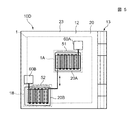
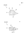
図5は本発明の第4の実施の形態としての電子発熱体の冷却装置を構成するソケットを示す図1同様の平面図、図6はマイクロポンプの構成を示す断面図であり、Aは正圧状態、Bは負圧状態を示している。
Next, a fourth embodiment of the present invention will be described.
FIG. 5 is a plan view similar to FIG. 1 showing a socket constituting a cooling device for an electronic heating element as a fourth embodiment of the present invention, FIG. 6 is a cross-sectional view showing the configuration of the micropump, and A is a positive view. A pressure state, B indicates a negative pressure state.
図5に示すように、駆動状態にある電子発熱体1の表面の温度分布を測定してみると、中央の領域に高温部1Aを有し、その周辺部に前記高温部1Aよりも温度の低い低温部1Bを有する構成が一般的である。そこで、第4の実施の形態では、このような電子発熱体1の表面(放熱面)に温度分布が現れることを利用するようにしたものである。
As shown in FIG. 5, when the temperature distribution on the surface of the
図5に示すソケット10Dも上記各実施の形態に示したソケット10Aないし図Cとほぼ同様の構成であり、マザーボード5上に固定されたハウジング11と、ヒンジ部13において回動自在に設けられた蓋体12とから構成されている。
The
ただし、第4の実施の形態に示す冷却装置では、複数のヒートシンク20A,20Bが分散された形態で設けられている点で異なっている。このうち、上面中央に設けられたヒートシンク20Aが高温部1A用であり、前記上面中央から離れた周辺側に設けられたヒートシンク20Bが低温部1B用である。
However, the cooling device shown in the fourth embodiment is different in that a plurality of
前記ヒートシンク20A,20Bは、ソケット10の蓋体12に形成された前記開口部12Aを通じて電子発熱体1の表面に直接固定されていてもよいし、前記開口部12Aを有しないソケット10にあっては、蓋体12の表面に一体として形成され又は固定されたものであってもよい。なお、前記ヒートシンク20A,20Bの上部には互いに平行に配置された複数の放熱フィン21,21,・・・・を有している点では同様の構成である。
The heat sinks 20A and 20B may be directly fixed to the surface of the
前記ヒートシンク20A,20Bのそれぞれの前記放熱フィン21の間には、上記第1の実施の形態同様に蛇行状のパイプからなる冷却管51,52が配置されている。前記冷却管51と冷却管52とは1本のパイプを折り曲げて連続的に形成されている。あるいは、蛇行状に折り曲げた微細な径寸法のパイプを複数本束ねることにより、前記冷却管51及び冷却管52を形成したものであってもよい。
Between the
また前記冷却管51と冷却管52とがそれぞれ別々に形成されており、前記冷却管51の一端と前記冷却管52の一端との間が別のパイプやチューブなどで連結された構成であってもよい。
The cooling
図5に示すように、前記冷却管51,52の各他端にはマイクロポンプが60A,60Bが接続されている。前記マイクロポンプ60A,60Bは、例えば図6A,図6Bに示すような冷媒としての冷却液35を収容する圧力室61と、前記圧力室61の一面に設けられるとともに弾性変形するダイヤフラム62と、前記ダイヤフラム62上に設置されダイヤフラム62を変形させる駆動手段63などを備えている。駆動手段63としては、例えば、PZT、TiNi、静電駆動用電極材料、誘電エラストマーに両面に対向電極をそれぞれ設けて形成した人工筋肉等を用いることができる。また、ダイヤフラム62としは、例えば金属、Si、ポリSi、ゴム、その他の各種プラスチック材料等により薄膜状に成形され弾性的に変形するものが用いられる。上記駆動手段63がダイヤフラム62を弾性変形させると、前記圧力室61の容積を変化させることが可能となっている。
As shown in FIG. 5,
前記冷却管51,52内には前記冷却液35が充填されており、かつ、密閉状態となっている。前記マイクロポンプ60Aのダイヤフラム62と前記マイクロポンプ60Bのダイヤフラム62とは相補的な関係を維持しながら交互に駆動させられる。すなわち、前記マイクロポンプ60Aのダイヤフラム62が図6Aに示す正圧の状態(容積を増大させた状態)に駆動させられるときには前記マイクロポンプ60Bのダイヤフラム62は図6Bに示す負圧の状態(容積を減少させた状態)に駆動させられ、前記マイクロポンプ60Aのダイヤフラム62が負圧に駆動させられるときには前記マイクロポンプ60Bのダイヤフラム62が正圧の状態に駆動させられる。
The cooling
このため、前記冷却管51,52内に充填されている前記冷却液35を互いに正逆の双方向(冷却管51から冷却管52に向かう方向、および冷却管52から冷却管51に向かう方向)に移動させるポンプとして機能させることが可能となっている。
For this reason, the cooling
なお、前記マイクロポンプ60A,60Bの駆動手段63を相補的に駆動させるための所定の電気信号を生成するドライバ手段などが設けられている(図示せず)。前記マイクロポンプ60A,60Bは前記ドライバ手段からの電気信号を受けて交互に駆動させられるようになっている。
In addition, driver means for generating a predetermined electric signal for driving the driving means 63 of the
このように前記マイクロポンプ60A,60Bを交互に駆動させることにより、前記高温部1Aに設けられた冷却管51内で暖められた冷却液35を前記低温部1Bに設けられた冷却管52に移動させることができる。そして、前記低温部1B側の冷却管52内で冷やされた冷却液35を前記高温部1A側の冷却管51に再び移動させることができる。すなわち、前記高温部1Aに位置する冷却管51と前記低温部1Bに位置する冷却管52との間で、冷媒としての冷却液35を移動させることによる熱交換を行うことが可能となっている。このため、前記図5に示す本発明の第4の実施の形態においても、電子発熱体1が発する熱を冷却することができる。このため、電子発熱体1本体の温度上昇、さらには前記電子発熱体1を有するPCケース内の温度上昇を抑制することができる。
Thus, by alternately driving the
第4の実施の形態に示すものでは、マイクロポンプ60A,60Bの駆動手段として小型のPZTなどを用いることができ、しかもラジエータを必要としないため、小型且つ省電力性に優れた冷却装置とすることが可能である。
In the fourth embodiment, a small PZT or the like can be used as the driving means for the
またさらに上記同様にファンを用いて前記ヒートシンク20A,20Bを強制的に空冷するようにすると、さらに冷却能力の高い冷却装置とすることが可能となる。
Further, if the
また上記第4の実施の形態では、一つの高温部1Aに一つの低温部1Bが対応し、これらの間でのみ熱交換が行なわれる構成を示したが、本発明はこれに限られるものではない。すなわち、一つの高温部1Aに複数の低温部1Bが対応して熱交換が行なわれる構成としたものであってもよく、この場合にはさらに冷却能力に優れた冷却装置とすることができる。
In the fourth embodiment, one
次に本発明の第5の実施の形態について説明する。
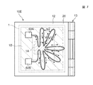
図7は本発明の第5の実施の形態としての電子発熱体の冷却装置を構成するソケットを示す図1同様の平面図である。
Next, a fifth embodiment of the present invention will be described.
FIG. 7 is a plan view similar to FIG. 1 showing a socket constituting a cooling device for an electronic heating element as a fifth embodiment of the present invention.
図7では、ソケット10Eを構成する蓋体12の表面に、一本のパイプを折り曲げるとともに前記蓋体12の中心部の周辺部との間に平面スター状(略放射状また扇状ともいう。)に配置した冷却管70が固定されている構成を示している。前記冷却管70の中心部側は前記電子発熱体1の高温部1A内を通過し、且つ前記冷却管70の周辺部は、前記高温部1Aよりも低い温度となる前記電子発熱体1の低温部1Bに対向するように配置されている、また隣り合う前記冷却管70間のピッチ幅は、高温部1Aのピッチ幅W1の方が低温部1B側のピッチ幅W2に比較して広くなる形状で形成されている。
In FIG. 7, a single pipe is bent on the surface of the
前記略ひだ状に配置された冷却管70の内部には冷却液35が充填されており、前記冷却管70の両端部には,上記第4の実施の形態と同様のマイクロポンプ60A,60Bがそれぞれ設けられている。前記マイクロポンプ60A,60Bは上記同様に交互に駆動させられるようになっている。
いる。
A cooling
Yes.
前記マイクロポンプ60A,60Bを交互に駆動すると、前記冷却管70内を冷却液35が前記マイクロポンプ60Aからマイクロポンプ60Bに向かう正方向、およびその逆方向の双方向に移動させることができる。このため、前記高温部1Aで暖められた冷却液35を前記低温部1Bに移動させることができる。また前記低温部1Bで冷やされた冷却液35を前記高温部1Aに移動させることができる。すなわち、前記高温部1Aに位置する冷却管70と前記低温部1Bに位置する冷却管70との間で、冷媒としての冷却液35を移動させることによる熱交換を行うことが可能である。このため、前記図7に第5の実施の形態として示す示するものにおいても、ソケット10E内に保持されている電子発熱体1が発した熱を冷却することができる。このため、電子発熱体1本体の温度上昇、さらには前記電子発熱体1を有するPCケース内の温度上昇を抑制することができる。
When the
また第5の実施の形態に示す冷却装置では、高温部1Aの冷却管70のピッチ幅W1の方が、低温部1B側の冷却管70のピッチ幅W2に比較して広い。このため、低温部1Bに位置する冷却管70の単位長さ当たりの冷却面積を広くすることができ、冷却管70を一定のピッチ幅で配置した場合(例えば図5参照)に比較して冷却液35を効率良く冷却することが可能である。
In the cooling device shown in the fifth embodiment, the pitch width W1 of the cooling pipe 70 of the
次に本発明の第5の実施の形態について説明する。
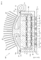
図8は本発明の第6の実施の形態としての電子発熱体の冷却装置を構成するソケットを示す図4同様の断面図である。
Next, a fifth embodiment of the present invention will be described.
FIG. 8 is a cross-sectional view similar to FIG. 4 showing a socket constituting a cooling device for an electronic heating element as a sixth embodiment of the present invention.
図8に示すソケット10Fは、蓋体12の構造とハウジング11の内壁11C,11Dに注入口41と排出口42が設けられている点を除いてほぼ上記第3の実施の形態に示すソケット10Cと同様である。
The
第6の実施の形態に示すソケット10Fを形成する蓋体12の表面はドーム形状をしており、その表面には円筒状の細管からなる複数のヒートパイプ81が植設されている。前記ヒートパイプ81は、細管を減圧状態で密閉されており、その内部には例えば水、ナトリウム、カリウム、フロンなどからなる作動液(熱媒体)が封入されている。前記ヒートパイプ81の管壁には溝や金網などからなり、毛細管現象を発揮するウイック(図示せず)が設けられている。また前記蓋体12の内側には、前記電子発熱体1の表面を図示Z1方向に押圧する押圧部12bが一体に形成されている。
The surface of the
なお、前記ソケット10Fの外部には、前記複数のヒートパイプ81を空冷するファンを設けた構成が好ましい。
A configuration in which a fan for air-cooling the plurality of
第6の実施の形態に示す電子発熱体の冷却装置では、前記電子発熱体1から発せられた熱が前記押圧部12bを介して前記蓋体12に伝達される。このとき、前記ヒートパイプ81の作動液は、ヒートパイプ81の一端である前記蓋体12側の端部(蒸発部)で熱を吸収し、他方の開放端部(凝縮部)で熱を放散する。すなわち、前記作動液は前記蒸発部で潜熱を奪って気化し、凝縮部で潜熱を捨てて液化する。液化した作動液は、気体より重いので前記ウイックを伝わって前記蒸発部に戻る(毛細管現象)。つまり、前記作動液は前記ヒートパイプ81内で液体→気体→液体と循環されることで熱対流を発生させるため、前記電子発熱体1が発した熱をソケット10Fの外部に逃がし冷却することができる。
In the cooling device for the electronic heating element shown in the sixth embodiment, the heat generated from the
また、図8に示すように前記蓋体12に複数の貫通孔を形成し、開放状態にしたヒートパイプ81の一端(蒸発部)を前記貫通孔に装着した構成であってもよい。この構成では、ソケット10F内で暖められて気化した作動液が、前記ヒートパイプ81内に滲入することができる。そして、上記同様の作用より前記電子発熱体1が発した熱をソケット10Fの外部に逃がすことができる。この実施の形態では、熱を吸収した作動液がヒートパイプ81に入り込むとともに他方の開放端部(凝縮部)に移動して直接的に熱を放散することができるため、さらに効率良く前記電子発熱体1を冷却することが可能となる。
Further, as shown in FIG. 8, a configuration may be adopted in which a plurality of through holes are formed in the
なお、上記第6の実施の形態では、複数のヒートパイプ81がドーム状の蓋体の表面に設けられた構成を用いて説明したが、本発明はこれに限られるものではなく、例えば図2などに示すソケットの蓋体12上に前記ヒートシンク20の代わりに複数のヒートパイプ81が設けられる構成であってもよい。
In the sixth embodiment, the description has been given using the configuration in which the plurality of
次に、冷却装置の一種としてのヒートシンクの新たな態様について説明する。
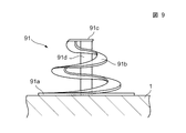
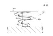
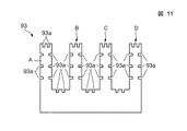
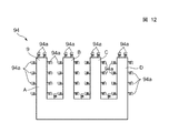
図9ないし図14はヒートシンクの実施の形態を示す側面図である。
Next, a new aspect of the heat sink as a kind of cooling device will be described.
9 to 14 are side views showing an embodiment of a heat sink.
図9および図10に示すヒートシンク91,92は、先端部が周縁部から中心に向かって渦巻き形状に立ち上がる放熱部を備えたスパイラル形状のヒートシンクである。 The heat sinks 91 and 92 shown in FIG. 9 and FIG. 10 are spiral heat sinks each having a heat radiating portion whose tip portion rises in a spiral shape from the peripheral edge toward the center.
ただし、図9に示すヒートシンク91は、マウント部91aが電子発熱体1の表面に固定されており、スパイラル状の放熱部91bの先端91cと電子発熱体1の表面との間には熱伝導部91dが設けられている。
However, the
一方、図10に示すヒートシンク92は、スパイラル状の放熱部92bの先端92cが電子発熱体1の表面に固定されており、熱伝導部92dがマウント部92aと電子発熱体1の表面との間に設けられている。
On the other hand, in the
前記ヒートシンク91は面積の大きなマウント部91aの全体が、電子発熱体1の表面に固定されるため、表面全体から熱を発するような電子発熱体1に向いている。また前記ヒートシンク92は、面積の小さな先端部92cが電子発熱体1の表面に固定されるため、特に表面の中央部から部分的に熱を発するような電子発熱体1に向いている。
The
なお、いずれのヒートシンク91,92においても、電子発熱体1の表面から発せられる熱を前記スパイラル状の放熱部91b,92b以外の熱伝導部91d,熱伝導部92dを介して最短経路で放熱することが可能である。
In any of the heat sinks 91 and 92, the heat generated from the surface of the
次に、図11に示すヒートシンク93は、従来のヒートシンク同様に複数の放熱フィンA,B,CおよびDを有している。ただし、これら各放熱フィンA,B,CおよびDに表面には、多数の凹部93aが形成されている点で異なっている。
Next, the
この実施の形態に示すヒートシンク93では、実質的な表面積を従来のヒートシンクよりも大きくすることができりため、より高い冷却能力を有するヒートシンクとすることが可能である。
In the
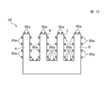
一方、図12および図13に示すヒートシンク94,95では、複数の放熱フィンA,B,CおよびDの表面に、例えば微細加工により形成された多数のスパイラル94a,95aが設けられている。なお、図12に示すヒートシンク94は前記図10同様にスパイラル94aの先端部が放熱フィンの表面に固定されたものであり、図13に示すヒートシンク95はゼンマイ形状に形成されたスパイラル95aの最外周部の端部が前記放熱フィンA,B,CおよびDの表面に固定されたものである。
On the other hand, in the heat sinks 94 and 95 shown in FIGS. 12 and 13, a large number of
これら実施の形態においても、前記多数のスパイラル94a,95aがヒートシンク全体の実質的な表面積を拡張することができる。よって、ヒートシンク94,95の全体としての冷却能力を高めることが可能である。
Also in these embodiments, the
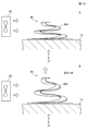
次に、図14は自己調整機能を備えたヒートシンクの側面図を示し、Aは常温時の圧縮状態、Bは高温時の膨張状態を示している。 Next, FIG. 14 shows a side view of a heat sink having a self-adjusting function, where A shows a compressed state at normal temperature and B shows an expanded state at high temperature.
図14に示すヒートシンク96は、上記図9に示すヒートシンク91に近似する構成であるが、中央に熱導伝導部91dを有しない点、および形状記憶合金で形成されている点が異なっている。例えば、形状記憶の性質を示す合金として、Ti−Ni合金、Au−Cd合金、Ag−Cd合金、Cu−Au−Zn合金等を用いることができる。
The
図14Bに示すように、前記ヒートシンク96は常温時の形状として図14Aに示すように放熱部がZ方向に縮んだ圧縮状態が記憶され、高温時の形状としてスパイラルの放熱部がZ2方向に立ち上がった膨張状態が記憶されている。したがって、電子発熱体1が熱を発する前の常温近傍では、前記ヒートシンク96は図14Aに示す圧縮状態にある。そして、前記電子発熱体1が動作させられ、自らが発する熱により電子発熱体1の表面の温度が高くなると、このときの温度の上昇にしたがって前記ヒートシンク96の形状は図14Bに示すような膨張状態に変形させられる。
As shown in FIG. 14B, the
前記圧縮状態のときには、ヒートシンク96の前記放熱部96bの姿勢が水平姿勢に近い状態(図14A)にあるが、徐々に温度が上昇すると前記放熱部96bを図14Bに示すような垂直に近い姿勢に近づけることができる。このため、例えばファン39からヒートシンク96に向けて送られて来る空気が、前記放熱部96bに当たる面積を温度の上昇とともに拡張することができる。すなわち、ヒートシンク96は、自らが有する冷却能力を電子発熱体1の温度上昇に合わせて高めることが可能となる。このため、ヒートシンク96は温度の変化に合わせて冷却能力を自己調整することができ、好適なヒートシンクを提供することが可能となる。
In the compressed state, the posture of the
上記第1ないし第3の実施の形態では、好ましい態様として冷却管で形成される循環経路内にラジエータ32等を設けて冷却液35を強制的に冷却する構成について説明したが、単に冷却液35を循環させるだけでも十分な冷却能力を発揮することが可能な冷却システムにおいては、前記ラジエータは必須のものではない。
In the first to third embodiments, the configuration in which the
ソケット 10,10A,10B,10C,10D,10E
11 ハウジング
11a 凹部
11b 被掛止部
12 蓋体
13 ヒンジ部
14 掛止部
15 インターポーザ
16,17 弾性接点
18,19 導電体
20,20A,20B ヒートシンク
21 放熱フィン
23,25 冷却管
31 ポンプ
32 ラジエータ
35 冷却液
39 ファン
41 注入口
42 排出口
51,52 冷却管
60A,60B マイクロポンプ
61 圧力室
62 ダイヤフラム
63 駆動手段
70 冷却管
81 ヒートパイプ
91,92,93,94,95 ヒートシンク
91a,92a マウント部
91b,92b 放熱部
91c,92c 先端
91d,92d 熱伝導部
93a 凹部
96 ヒートシンク
96b 放熱部
A,B,C,D 放熱フィン
DESCRIPTION OF
Claims (12)
Priority Applications (1)
| Application Number | Priority Date | Filing Date | Title |
|---|---|---|---|
| JP2005144408A JP4508939B2 (en) | 2005-05-17 | 2005-05-17 | Electronic heating element cooling device |
Applications Claiming Priority (1)
| Application Number | Priority Date | Filing Date | Title |
|---|---|---|---|
| JP2005144408A JP4508939B2 (en) | 2005-05-17 | 2005-05-17 | Electronic heating element cooling device |
Publications (2)
| Publication Number | Publication Date |
|---|---|
| JP2006324345A true JP2006324345A (en) | 2006-11-30 |
| JP4508939B2 JP4508939B2 (en) | 2010-07-21 |
Family
ID=37543818
Family Applications (1)
| Application Number | Title | Priority Date | Filing Date |
|---|---|---|---|
| JP2005144408A Expired - Fee Related JP4508939B2 (en) | 2005-05-17 | 2005-05-17 | Electronic heating element cooling device |
Country Status (1)
| Country | Link |
|---|---|
| JP (1) | JP4508939B2 (en) |
Cited By (6)
| Publication number | Priority date | Publication date | Assignee | Title |
|---|---|---|---|---|
| JP2012099528A (en) * | 2010-10-29 | 2012-05-24 | Fujitsu Ltd | Electronic device |
| JP2018206790A (en) * | 2017-05-30 | 2018-12-27 | カルソニックカンセイ株式会社 | Semiconductor device cooling system |
| WO2020031788A1 (en) * | 2018-08-10 | 2020-02-13 | 豊田合成株式会社 | Electronic device |
| JP2020028187A (en) * | 2018-08-10 | 2020-02-20 | 豊田合成株式会社 | Electronic apparatus |
| JP2020027395A (en) * | 2018-08-10 | 2020-02-20 | 豊田合成株式会社 | Electronic apparatus |
| CN118016618A (en) * | 2023-12-27 | 2024-05-10 | 潍坊勤俭持家网络科技有限公司 | An IGBT semiconductor device structure |
Families Citing this family (1)
| Publication number | Priority date | Publication date | Assignee | Title |
|---|---|---|---|---|
| US11749923B2 (en) | 2021-04-15 | 2023-09-05 | Te Connectivity Solutions Gmbh | Cooling system for socket connector |
Citations (5)
| Publication number | Priority date | Publication date | Assignee | Title |
|---|---|---|---|---|
| JPH02304997A (en) * | 1989-05-19 | 1990-12-18 | Nec Corp | Heat radiator |
| JP2001264381A (en) * | 2000-03-14 | 2001-09-26 | Pfu Ltd | Semiconductor package inspection socket, semiconductor package inspection system, control method therefor, and recording medium therefor |
| JP2003243593A (en) * | 2002-02-22 | 2003-08-29 | Sanyo Electric Co Ltd | Electronic device |
| JP2004171835A (en) * | 2002-11-18 | 2004-06-17 | Ebara Ballard Corp | Fuel cell device |
| JP2005003352A (en) * | 2003-05-21 | 2005-01-06 | Kri Inc | Heat transport device |
-
2005
- 2005-05-17 JP JP2005144408A patent/JP4508939B2/en not_active Expired - Fee Related
Patent Citations (5)
| Publication number | Priority date | Publication date | Assignee | Title |
|---|---|---|---|---|
| JPH02304997A (en) * | 1989-05-19 | 1990-12-18 | Nec Corp | Heat radiator |
| JP2001264381A (en) * | 2000-03-14 | 2001-09-26 | Pfu Ltd | Semiconductor package inspection socket, semiconductor package inspection system, control method therefor, and recording medium therefor |
| JP2003243593A (en) * | 2002-02-22 | 2003-08-29 | Sanyo Electric Co Ltd | Electronic device |
| JP2004171835A (en) * | 2002-11-18 | 2004-06-17 | Ebara Ballard Corp | Fuel cell device |
| JP2005003352A (en) * | 2003-05-21 | 2005-01-06 | Kri Inc | Heat transport device |
Cited By (7)
| Publication number | Priority date | Publication date | Assignee | Title |
|---|---|---|---|---|
| JP2012099528A (en) * | 2010-10-29 | 2012-05-24 | Fujitsu Ltd | Electronic device |
| JP2018206790A (en) * | 2017-05-30 | 2018-12-27 | カルソニックカンセイ株式会社 | Semiconductor device cooling system |
| WO2020031788A1 (en) * | 2018-08-10 | 2020-02-13 | 豊田合成株式会社 | Electronic device |
| JP2020028187A (en) * | 2018-08-10 | 2020-02-20 | 豊田合成株式会社 | Electronic apparatus |
| JP2020027395A (en) * | 2018-08-10 | 2020-02-20 | 豊田合成株式会社 | Electronic apparatus |
| JP7035901B2 (en) | 2018-08-10 | 2022-03-15 | 豊田合成株式会社 | Electronics |
| CN118016618A (en) * | 2023-12-27 | 2024-05-10 | 潍坊勤俭持家网络科技有限公司 | An IGBT semiconductor device structure |
Also Published As
| Publication number | Publication date |
|---|---|
| JP4508939B2 (en) | 2010-07-21 |
Similar Documents
| Publication | Publication Date | Title |
|---|---|---|
| US7675163B2 (en) | Carbon nanotubes for active direct and indirect cooling of electronics device | |
| KR20050081842A (en) | Liquid cooling system and electric device having the same | |
| US20050135062A1 (en) | Heat sink, assembly, and method of making | |
| CN100470773C (en) | heat pipe radiator | |
| US20100147496A1 (en) | Heat dissipation device with heat pipe | |
| WO2003043397A1 (en) | Electronic apparatus | |
| JP2007059917A (en) | Combined heat dissipation device | |
| JP4234722B2 (en) | Cooling device and electronic equipment | |
| JP4551261B2 (en) | Cooling jacket | |
| JP4508939B2 (en) | Electronic heating element cooling device | |
| JP2004293833A (en) | Cooling device | |
| CN115052461A (en) | Pulsating heat pipe heat dissipation device and heat dissipation system | |
| JP5667739B2 (en) | Heat sink assembly, semiconductor module, and semiconductor device with cooling device | |
| JP2006046868A (en) | Radiator and heat pipe | |
| JP2001251079A (en) | Heat sink using heat pipe and method of manufacturing heat pipe | |
| JP7602009B2 (en) | In-vehicle electronic devices | |
| CN111683494B (en) | Composite radiator and processing method thereof | |
| KR101408949B1 (en) | Radiator with built-in oil cooler | |
| CN216014193U (en) | cooling device | |
| JP5624771B2 (en) | Heat pipe and heat sink with heat pipe | |
| EP2002194A2 (en) | Low cost boiling coolers utilizing liquid boiling | |
| JP4744280B2 (en) | Electronic equipment with cooling mechanism | |
| KR100488104B1 (en) | Plate Radiator Structure of CPU Cooling Module | |
| CN221900000U (en) | Heat sink and electronic components | |
| JP2005340745A (en) | Power supply unit for electrical and electronic equipment |
Legal Events
| Date | Code | Title | Description |
|---|---|---|---|
| A621 | Written request for application examination |
Free format text: JAPANESE INTERMEDIATE CODE: A621 Effective date: 20070925 |
|
| A977 | Report on retrieval |
Free format text: JAPANESE INTERMEDIATE CODE: A971007 Effective date: 20100119 |
|
| A131 | Notification of reasons for refusal |
Free format text: JAPANESE INTERMEDIATE CODE: A131 Effective date: 20100202 |
|
| A521 | Written amendment |
Free format text: JAPANESE INTERMEDIATE CODE: A523 Effective date: 20100329 |
|
| TRDD | Decision of grant or rejection written | ||
| A01 | Written decision to grant a patent or to grant a registration (utility model) |
Free format text: JAPANESE INTERMEDIATE CODE: A01 Effective date: 20100420 |
|
| A01 | Written decision to grant a patent or to grant a registration (utility model) |
Free format text: JAPANESE INTERMEDIATE CODE: A01 |
|
| A61 | First payment of annual fees (during grant procedure) |
Free format text: JAPANESE INTERMEDIATE CODE: A61 Effective date: 20100427 |
|
| FPAY | Renewal fee payment (prs date is renewal date of database) |
Free format text: PAYMENT UNTIL: 20130514 Year of fee payment: 3 |
|
| R150 | Certificate of patent (=grant) or registration of utility model |
Free format text: JAPANESE INTERMEDIATE CODE: R150 |
|
| LAPS | Cancellation because of no payment of annual fees |