JP2006314278A - Brush cutter - Google Patents
Brush cutter Download PDFInfo
- Publication number
- JP2006314278A JP2006314278A JP2005141397A JP2005141397A JP2006314278A JP 2006314278 A JP2006314278 A JP 2006314278A JP 2005141397 A JP2005141397 A JP 2005141397A JP 2005141397 A JP2005141397 A JP 2005141397A JP 2006314278 A JP2006314278 A JP 2006314278A
- Authority
- JP
- Japan
- Prior art keywords
- cutter
- electric motor
- brush cutter
- engine
- driven
- Prior art date
- Legal status (The legal status is an assumption and is not a legal conclusion. Google has not performed a legal analysis and makes no representation as to the accuracy of the status listed.)
- Pending
Links
Images


Abstract
Description
本発明はエンジンと電動モータのいずれをも動力源としてカッターを駆動し得るようにした刈払機に関する。 The present invention relates to a brush cutter capable of driving a cutter using either an engine or an electric motor as a power source.
田畑の畦道や川原の土手に生える雑草、山林の下草や牧草等を刈り取るために草刈機とも言われる刈払機が使用されている。刈払機には、操作アームの先端にカッターを取り付け後端に動力源を装着するようにしたアーム連結タイプと、動力源の回転軸に直接カッターを取り付けるようにした直動タイプとがあり、動力源としてはエンジンを装着する場合と電動モータを装着する場合とがある。 Brush cutters, also called mowers, are used to cut weeds that grow on the banks of Tabata and the banks of Kawahara, undergrowth and pasture of mountain forests. There are two types of brush cutters: an arm connection type in which a cutter is attached to the tip of the operating arm and a power source is attached to the rear end, and a direct-acting type in which a cutter is directly attached to the rotary shaft of the power source. As a source, there are a case where an engine is mounted and a case where an electric motor is mounted.
電動モータを動力源とする刈払機には、例えば特許文献1に記載されるように、操作アームの先端に電動モータを装着し、電動モータのシャフトにカッターを直接取り付けるようにした直動タイプが多い。エンジンを動力源とする刈払機には、例えば特許文献2に記載されるように、操作アームの先端にカッターを取り付け、後端にエンジンを装着するようにしたアーム連結タイプが多い。 A brush cutter using an electric motor as a power source is, for example, a linear motion type in which an electric motor is attached to the tip of an operation arm and a cutter is directly attached to the shaft of the electric motor, as described in Patent Document 1. Many. As described in Patent Document 2, for example, there are many arm connection types in which a cutter is attached to the front end of the operation arm and the engine is attached to the rear end.
操作アームの先端にカッターを取り付け、後端にエンジンを装着するようにしたアーム連結タイプには、背負い架台にエンジンを搭載するようにした背負い式、操作アームに取り付けられたループ状のベルトを肩に掛けるようにした肩掛け式、及び操作アームに設けられたハンドルを手に持って操作するようにしたハンドル式等があり、ハンドルにはループハンドルと両手ハンドルとがある。 The arm connection type with the cutter attached to the front end of the operation arm and the engine attached to the rear end has a shoulder-type loop belt attached to the operation arm. There are a shoulder type that can be hung on a handle, a handle type that is operated by holding a handle provided on an operation arm, and the handle has a loop handle and a two-hand handle.
これらの刈払機に取り付けられるカッターには複数の切刃が設けられた円板状の金属刃があり、金属刃には刃数の違いにより4枚刃、8枚刃、及び30枚以上の切刃が鋸刃状に設けられたものがある。金属刃には切断エッジを切刃の回転方向一方側の側面にのみ設けるようにした片刃式のものが多く用いられている。このような片刃式のカッターを刈払機に取り付けて刈り取り作業を行う場合には、回転するカッターを地面に対してほぼ平行に移動させることにより、進行方向側の切刃の切断エッジを雑草等に接触させてこれを刈り取ることになる。
通常の刈払機には作業者の安全を確保するためにカッターの作業者側を覆うようにカバーが取り付けられており、刈り取った雑草等の刈葉がカッターとカバーとの間に絡み付いてカッターがロックして回転が停止することがあり、さらには切れなかった雑草等がカバーやカッターの回転軸に絡み付いたり切刃に樹木等の異物が食い込んだりしてカッターがロックしてしまうこともある。 A normal brush cutter has a cover that covers the operator side of the cutter in order to ensure the safety of the operator, and mowing leaves such as weeds that have been cut are entangled between the cutter and the cover. The rotation may be stopped by locking, and weeds that have not been cut may be entangled with the rotation axis of the cover or the cutter, or foreign matter such as trees may be caught in the cutting blade and the cutter may be locked.
このようにして刈葉等によってカッターがロックした場合には、従来では、動力源の作動を停止させてから手作業によりカッターを逆転させることによってカッターに絡み付いた刈葉等を取り除く必要があり、刈葉除去作業を安全かつ容易に行うことが困難である。 When the cutter is locked by cutting leaves in this way, conventionally, it is necessary to remove the cutting leaves entangled with the cutter by manually reversing the cutter after stopping the operation of the power source, It is difficult to perform the mowing leaf removal work safely and easily.
本発明の目的は、刈払機をその使用環境に応じてエンジンと電動モータのいずれをも動力源として駆動し得るとともに電動モータにより駆動している際にカッターが刈葉等によりロックしたときに容易にロックを解除し得るようにすることにある。 The object of the present invention is that the brush cutter can be driven by using either the engine or the electric motor as a power source according to the usage environment, and is easy when the cutter is locked by the cutting leaves or the like while being driven by the electric motor. It is to be able to release the lock.
本発明の刈払機は、先端にカッターが連結され他端に従動側連結部を有する従動軸が回転自在に装着される刈払機本体と、前記刈払機本体に着脱自在に装着され前記カッターを正逆両方向に駆動する電動モータとを有し、エンジンの出力軸に設けられ前記従動側連結部に連結される駆動側連結部が組み込まれたエンジン出力側ジョイントと、前記電動モータの出力軸に設けられ前記従動側連結部に連結される駆動側連結部が組み込まれたモータ側ジョイントとのいずれもが選択的に着脱自在に装着される従動側ジョイントを前記刈払機本体に設け、前記刈払機本体に前記電動モータが装着された状態のもとで前記電動モータにより駆動されている前記カッターがロックしたときに、前記カッターを逆転させるロック解除スイッチを前記刈払機本体に着脱自在に装着することを特徴とする。 The brush cutter according to the present invention includes a brush cutter main body to which a cutter is connected at the tip and a driven shaft having a driven side connecting portion at the other end is rotatably mounted, and the cutter is attached to the brush cutter main body to be detachable. An electric motor that drives in opposite directions, an engine output side joint that is provided on the output shaft of the engine and that is connected to the driven side connection portion, and an output shaft of the electric motor. The brush cutter body is provided with a driven side joint that is selectively detachably attached to any of the motor side joints that incorporate the drive side coupling portion coupled to the driven side coupling portion. A lock release switch that reverses the cutter when the cutter driven by the electric motor is locked with the electric motor attached to the brush cutter. Characterized by detachably attached to the body.
本発明の刈払機は、長手方向中央部に作業者により把持されるハンドルが設けられ前記従動軸が挿入される中空棒状の操作アームにより前記刈払機本体を形成することを特徴とする。 The brush cutter according to the present invention is characterized in that the brush cutter main body is formed by a hollow bar-shaped operation arm into which a handle gripped by an operator is provided at a central portion in the longitudinal direction and the driven shaft is inserted.
本発明の刈払機は、前記ロック解除スイッチをケーブルを介して前記電動モータに接続するとともに前記ハンドルに着脱自在に装着されるホルダに設けることを特徴とする。 The brush cutter according to the present invention is characterized in that the lock release switch is provided in a holder that is connected to the electric motor via a cable and is detachably attached to the handle.
本発明によれば、刈払機本体にエンジンと電動モータとのいずれかを選択的に装着することができ、エンジンと電動モータとをアタッチメントとして用意しておくことにより、刈り取り作業における使用環境に応じて刈払機をエンジン駆動式としてもモータ駆動式としても使用することができる。電動モータによりカッターを駆動している際に刈葉等がカッターに絡み付いてカッターの回転が止められた場合にロック解除スイッチを操作することにより、カッターを逆転させることができ、カッターに絡み付いた刈葉等を容易に取り除くことができる。 According to the present invention, either the engine or the electric motor can be selectively attached to the brush cutter main body, and the engine and the electric motor are prepared as attachments, so that it can be used according to the usage environment in the mowing work. The brush cutter can be used as an engine driven type or a motor driven type. When the cutter is driven by an electric motor and the leaf is entangled with the cutter and the rotation of the cutter is stopped, the cutter can be reversed by operating the lock release switch. Leaves can be easily removed.
本発明によれば、刈払機本体をハンドルが設けられた操作アームにより形成することにより、作業者はハンドルを把持して操作アームを操ることで刈り取り作業を行うことができる。電動モータに接続されたロック解除スイッチはホルダによりハンドルに着脱自在に装着することができ、ハンドルにロック解除スイッチを設けることによりハンドルを把持した状態でロック解除スイッチを操作することができ作業性が良い。 According to the present invention, the brush cutter main body is formed by the operation arm provided with the handle, so that the operator can perform the cutting operation by grasping the handle and operating the operation arm. The lock release switch connected to the electric motor can be detachably attached to the handle by the holder, and by providing the lock release switch on the handle, the lock release switch can be operated while the handle is gripped. good.
以下、本発明の実施の形態を図面に基づいて詳細に説明する。図1は本発明の一実施の形態である刈払機を示す斜視図であり、図1(A)は刈払機本体にエンジンを装着した状態を示し、図1(B)は刈払機本体に電動モータを装着した状態を示す。図1に示す刈払機はアーム連結タイプであり、刈払機本体としての操作アーム10を有している。操作アーム10は中空棒状の部材により構成されており、内部には従動軸11が回転自在に装着されている(図2及び図4参照)。
Hereinafter, embodiments of the present invention will be described in detail with reference to the drawings. FIG. 1 is a perspective view showing a brush cutter according to an embodiment of the present invention. FIG. 1 (A) shows a state in which an engine is mounted on a brush cutter body, and FIG. The state where the motor is mounted is shown. The brush cutter shown in FIG. 1 is of an arm connection type and has an
操作アーム10の先端部には支持部材12が取り付けられ、この支持部材12には金属製のカッター13が回転自在に取り付けられており、カッター13は従動軸11の先端に傘歯車対(図示省略)を介して連結されている。カッター13は複数の切刃14が鋸刃状に設けられた円板状の金属刃であり、切断エッジが切刃の回転方向一方側の側面にのみ設けられた片刃式である。操作アーム10の先端部にはカッター13の作業者側を覆うようにカバー15が取り付けられており、このカバー15によりカッター13に作業者が接触するのが防止され作業の安全が図られている。
A
操作アーム10の長手方向中央部には2つのハンドル16が取り付けられ、作業者はハンドル16を両手で把持することによりカッター13を地面から持ち上げて移動させることができる。なお、図示する場合には刈払機は操作アーム10に2つのハンドル16が取り付けられた両手ハンドル式であるが、これに代えてループハンドル式としても良く、操作アーム10にループ状の肩掛け用のベルトを取り付けて刈払機を肩掛け式としても良い。
Two
操作アーム10の後端部には刈払機本体側のジョイントとして従動側ジョイント17が取り付けられ、操作アーム10は従動側ジョイント17の部分で、図1(A)に示すようにエンジン18と、図1(B)に示すように電動モータ19とのいずれもが選択的に着脱自在に装着されるようになっている。
A driven
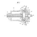
図2は図1(A)に示した刈払機の一部を示す拡大断面図であり、図3(A)はエンジンの正面図であり、図3(B)は同図(A)に示すエンジンの側面図である。エンジン18は4サイクルの単気筒ガソリンエンジンであり、エンジンカバー20内にはクランク軸からなるエンジン出力軸21を回転自在に支持するクランクケースが組み込まれており、クランクケースにはピストンが往復動自在に装着されるシリンダ等のエンジン構成部材(図示省略)が組み込まれている。エンジン出力軸21にはリコイルスタータが設けられており、リコイルノブ22を引っ張ることによりエンジン18を始動させることができる。燃料タンク23内のガソリンを燃料としてエンジン18を駆動させると、エンジン出力軸21に取り付けられた冷却ファン24がエンジン18を冷却する。
2 is an enlarged cross-sectional view showing a part of the brush cutter shown in FIG. 1 (A), FIG. 3 (A) is a front view of the engine, and FIG. 3 (B) is shown in FIG. It is a side view of an engine. The
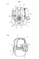
図4は図1(B)に示した刈払機の一部を示す拡大断面図であり、図5(A)は電動モータの正面図であり、図5(B)は同図(A)に示す電動モータの側面図である。電動モータ19は略六角柱形状のモータケース25を有し、このモータケース25にはアマチュアシャフトからなるモータ出力軸26が回転自在に支持されており、モータケース25内にはモータ出力軸26に固定されるアーマチュアやアーマチュアに対向するマグネット等のモータ構成部材(図示省略)が組み込まれている。また、電動モータ19の外周部にはリチウムイオン電池等の充電式バッテリ27が装着されており、このバッテリ27から供給される電力により電動モータ19を駆動させることができる。
4 is an enlarged sectional view showing a part of the brush cutter shown in FIG. 1 (B), FIG. 5 (A) is a front view of the electric motor, and FIG. 5 (B) is shown in FIG. It is a side view of the electric motor shown. The
図6(A)は従動側ジョイントの正面図であり、図6(B)は同図(A)に示す従動側ジョイントの側面図である。従動側ジョイント17は操作アーム10よりも大径のカップ状に形成され操作アーム10の後端部に取り付けられており、その開口端には正方形状のフランジ部28が設けられている。フランジ部28の四隅には締結部材であるボルト29がねじ込まれる締結孔28aが形成されている。
6A is a front view of the driven side joint, and FIG. 6B is a side view of the driven side joint shown in FIG. The driven joint 17 is formed in a cup shape having a larger diameter than the
図3(A)に示すように、エンジンカバー20には締結孔28aのそれぞれに対応する締結孔30aが形成されたエンジン出力側ジョイント30が設けられており、従動側ジョイント17のフランジ部28にエンジン出力側ジョイント30を突き合わせた状態で締結孔28a,30aのそれぞれにボルト29をねじ止めすることにより、従動側ジョイント17にエンジン18を着脱自在に装着することができる。図5(A)に示すように、モータケース25には締結孔28aのそれぞれに対応する締結孔31aが形成されたモータ出力側ジョイント31が設けられており、従動側ジョイント17のフランジ部28にモータ出力側ジョイント31を突き合わせた状態で締結孔28a,31aのそれぞれにボルト29をねじ止めすることにより、従動側ジョイント17に電動モータ19を着脱自在に装着することができる。なお、図2、図3に示す符号32はゴム製のシール部材である。
As shown in FIG. 3 (A), the
このような従動側ジョイント17の内部には、図2及び図4に示すように、従動軸11に固定され従動軸11と一体として回転するクラッチドラム33が組み込まれており、このクラッチドラム33により従動側連結部が構成されている。
As shown in FIGS. 2 and 4, a
エンジン出力側ジョイント30の内部には、図2に示すように、エンジン出力軸21の先端部に設けられる一対のクラッチシュー35が組み込まれており、このクラッチシュー35により駆動側連結部が構成されている。図1(A)に示すように、従動側ジョイント17にエンジン18が装着されたときには、これらのクラッチシュー35とクラッチドラム33とにより従動軸11とエンジン出力軸21との間に遠心クラッチ36が構成される。
As shown in FIG. 2, a pair of
図7は図2における横断面図である。図2に示すように、エンジン出力軸21には円板状の回転板37が固定され、図7に示すように、この回転板37にはピン38によりクラッチシュー35が揺動自在に装着されている。それぞれのクラッチシュー35には引っ張りコイルばね39が装着されており、この引っ張りコイルばね39によりクラッチシュー35のそれぞれには摩擦接触部35aがクラッチドラム33の内周面から離れる方向のばね力が加えられている。
FIG. 7 is a cross-sectional view in FIG. As shown in FIG. 2, a disk-shaped rotating
これにより、リコイルノブ22を引っ張ってエンジン18を始動させるときには、遠心クラッチ36が開放状態となっておりリコイルノブ22には大きな抵抗力が加わらないので容易にエンジン18を始動させることができる。更に、エンジン回転数の上昇にともない増加する遠心力により、クラッチシュー35は引っ張りコイルばね39のばね力に抗して拡開しクラッチドラム33の内周面に押し付けられてクラッチドラム33と連結され、エンジン出力軸21は遠心クラッチ36を介して従動軸11と直結状態とされることにより従動軸11を介してカッター13を回転させて草を刈り取ることができる。
Thus, when the
モータ出力軸26の先端部には駆動側連結部としての一対のクラッチシュー40が設けられ、これらのクラッチシュー40はモータ出力側ジョイント31に組み込まれており、図1(B)に示すように、従動側ジョイント17がモータ出力側ジョイント31に締結されたときには、これらのクラッチシュー40とクラッチドラム33とにより従動軸11とモータ出力軸26との間に遠心クラッチ41が構成される。
A pair of
図4に示すように、モータ出力軸26には円板状の回転板42が固定され、この回転板42にピン(図示省略)を用いてクラッチシュー40が揺動自在に装着されている。それぞれのクラッチシュー40には引っ張りコイルばね43が装着されており、この引っ張りコイルばね43によりクラッチシュー40のそれぞれには摩擦接触部40aがクラッチドラム33の内周面から離れる方向のばね力が加えられている。
As shown in FIG. 4, a disc-shaped rotating
これにより、電動モータ19の回転数の上昇にともない増加する遠心力により、クラッチシュー40は引っ張りコイルばね43のばね力に抗して拡開しクラッチドラム33の内周面に押し付けられてクラッチドラム33と連結され、モータ出力軸26は遠心クラッチ41を介して従動軸11と直結状態とされることにより従動軸11を介してカッター13を回転させて草を刈り取ることができる。更に、カッター13に草が絡まる等してバッテリ27から駆動電流が供給された状態のままカッター13の回転が停止したときには、クラッチドラム33に対してクラッチシュー40が滑ることによりモータ出力軸26は回転し続け、電動モータ19に過電流が流れることが防止される。この電動モータ19に対して供給される電力を制御することによりモータ出力軸26の回転数及び回転方向を自在に制御することができる。
As a result, the
図8(A)は図1(B)に示すハンドルに設けられるロック解除スイッチを拡大して示す斜視図であり、図8(B)はロック解除スイッチを有するモータ逆転回路を示す回路図である。ハンドル16のグリップ部分の近くには、モータ回転数を制御するための調整ダイアル44と回転方向を切り替えるためのロック解除スイッチ45を有するモータ調節器46が着脱自在に装着されている。このモータ調節器46はハンドル16に着脱自在に装着されるホルダ47を有しており、図示する場合には、ホルダ47は断面略C字形の装着バンド48を有しており、装着バンド48はその切り欠き部48aで拡開自在となっている。この切り欠き部48aにはボルト49が挿通されるようになっており、切り欠き部48aからハンドル16を嵌め込んだ後、切り欠き部48aにボルト49を挿通させてナット50を用いて締結することにより、ハンドル16に対してモータ調節器46を着脱自在に装着することができる。
FIG. 8A is an enlarged perspective view showing a lock release switch provided on the handle shown in FIG. 1B, and FIG. 8B is a circuit diagram showing a motor reverse rotation circuit having the lock release switch. . A
調整ダイアル44には可変抵抗器(図示省略)が組み込まれており、調整ダイアル44を回転操作することにより可変抵抗器の抵抗値を変化させることでバッテリ27から電動モータ19へ供給される駆動電流を変化させて、電動モータ19の回転数を調整することができる。電動モータ19の回転数を調整することにより従動軸11を介してカッター13の回転数を調整することができる。
A variable resistor (not shown) is incorporated in the
このモータ調節器46はケーブル51を介して電動モータ19に接続されており、図1(B)に示すように、電動モータ19を操作アーム10に装着する場合には、ホルダ47を用いてハンドル16に着脱自在に装着され、エンジン18を操作アーム10に装着する場合には、モータ調節器46は、図1(A)に示すように、ハンドル16から取り外される。ロック解除スイッチ45は、図8(b)に示すように、図示しないばね部材により常時モータ正転接点に接続され、ロック解除スイッチ45が押し込まれると、モータ駆動回路の逆転接点が導通状態となり、ロック解除スイッチ45が押し込まれている間だけ電動モータは逆転することになる。
The
ロック解除スイッチ45は、図示する場合には、ばね部材が組み込まれた押しボタン式のスイッチであり、通常時は図8(B)に示すようにモータ逆転回路の正転接点に保持されており、押圧されると一時的に逆転接点に接触して電動モータ19は逆転される。押圧状態が解除されてロック解除スイッチ45が元の位置に戻ると逆転接点は、図8(B)に示すように開かれて正転接点が接触しモータ出力軸26は再び正転するようになっている。逆転回路としては、図示される場合に限られず、ロック解除スイッチ45が一度押されると、所定の回転数、例えば1回転だけモータ出力軸26を逆回転させるようにしたり、数秒間だけモータ出力軸26を逆転させるようにしても良い。また、ロック解除スイッチ45の形状及び構造は図示する場合に限られず、作業者が操作することにより電動モータ19に逆転電流を送ることができるものであればスライド式、レバー式または回転式のスイッチ等でも良い。
In the illustrated case, the
このような刈払機においては、操作アーム10にエンジン18を装着して刈り取り作業を行うことができるとともに操作アーム10に電動モータ19を装着して刈り取り作業を行うことができる。電動モータ19によりカッター13を回転駆動して刈り取り作業を行っている際に、カッター13に刈葉が絡み付いたり異物が食い込んでカッター13がロックされて回転が停止したときには、ロック解除スイッチ45を操作することにより電動モータ19のモータ出力軸26を介してカッター13の回転方向を所定の回転数又は時間にわたって逆転させることができる。これにより、カッター13に絡み付いた刈葉等を安全かつ容易に取り除くことができ、作業性の向上を図ることができる。モータ調節器46をグリップ部分の近くに装着することにより、ハンドル16を把持した状態のままロック解除スイッチ45を指先で操作することができ、カッター13のロック解除作業を容易に行うことができる。
In such a brush cutter, the
本発明は前記実施の形態に限定されるものではなく、その要旨を逸脱しない範囲で種々変更可能である。例えば、本発明は直動タイプの刈払機や、走行台車に駆動源とカッターとを装着するようにしたタイプの刈払機にも適用することができる。 The present invention is not limited to the above-described embodiment, and various modifications can be made without departing from the scope of the invention. For example, the present invention can also be applied to a direct acting type brush cutter or a type of brush cutter in which a driving source and a cutter are mounted on a traveling carriage.
10 操作アーム
13 カッター
16 ハンドル
17 従動側ジョイント
18 エンジン
19 電動モータ
30 エンジン出力側ジョイント
31 モータ出力側ジョイント
45 ロック解除スイッチ
DESCRIPTION OF
Claims (3)
エンジンの出力軸に設けられ前記従動側連結部に連結される駆動側連結部が組み込まれたエンジン出力側ジョイントと、前記電動モータの出力軸に設けられ前記従動側連結部に連結される駆動側連結部が組み込まれたモータ側ジョイントとのいずれもが選択的に着脱自在に装着される従動側ジョイントを前記刈払機本体に設け、
前記刈払機本体に前記電動モータが装着された状態のもとで前記電動モータにより駆動されている前記カッターがロックしたときに、前記カッターを逆転させるロック解除スイッチを前記刈払機本体に着脱自在に装着することを特徴とする刈払機。 A brush cutter body that is rotatably connected with a driven shaft that has a cutter connected to the tip and a driven side connecting portion at the other end, and an electric motor that is detachably attached to the brush cutter body and drives the cutter in both forward and reverse directions. And
An engine output side joint provided with an output shaft of the engine and connected to the driven side connecting portion, and a drive side provided with an output shaft of the electric motor and connected to the driven side connecting portion The brush cutter body is provided with a driven side joint that is selectively detachably attached to any of the motor side joints in which the connecting portions are incorporated,
When the cutter driven by the electric motor is locked in a state where the electric motor is mounted on the brush cutter body, a lock release switch for reversing the cutter is detachably attached to the brush cutter body. A brush cutter characterized by being mounted.
Priority Applications (2)
| Application Number | Priority Date | Filing Date | Title |
|---|---|---|---|
| JP2005141397A JP2006314278A (en) | 2005-05-13 | 2005-05-13 | Brush cutter |
| US11/430,270 US7480998B2 (en) | 2005-05-09 | 2006-05-08 | Bush cutter |
Applications Claiming Priority (1)
| Application Number | Priority Date | Filing Date | Title |
|---|---|---|---|
| JP2005141397A JP2006314278A (en) | 2005-05-13 | 2005-05-13 | Brush cutter |
Publications (2)
| Publication Number | Publication Date |
|---|---|
| JP2006314278A true JP2006314278A (en) | 2006-11-24 |
| JP2006314278A5 JP2006314278A5 (en) | 2008-07-24 |
Family
ID=37535523
Family Applications (1)
| Application Number | Title | Priority Date | Filing Date |
|---|---|---|---|
| JP2005141397A Pending JP2006314278A (en) | 2005-05-09 | 2005-05-13 | Brush cutter |
Country Status (1)
| Country | Link |
|---|---|
| JP (1) | JP2006314278A (en) |
Cited By (15)
| Publication number | Priority date | Publication date | Assignee | Title |
|---|---|---|---|---|
| JP2009072150A (en) * | 2007-09-21 | 2009-04-09 | Hitachi Koki Co Ltd | Cordless horticultural tool |
| JP2010284164A (en) * | 2009-06-15 | 2010-12-24 | Chervon Ltd | Method for controlling reversal of blade of bush cutter |
| WO2011005156A1 (en) | 2009-07-09 | 2011-01-13 | Husqvarna Ab | Electrical two-way rotary trimmer |
| JP2011067097A (en) * | 2009-09-24 | 2011-04-07 | Ryobi Ltd | Bush cutter |
| JP2011250773A (en) * | 2010-06-04 | 2011-12-15 | Hitachi Koki Co Ltd | Hedge trimmer |
| WO2012132564A1 (en) * | 2011-03-31 | 2012-10-04 | 株式会社マキタ | Mobile operating machine having hybrid driving system |
| JP2012231804A (en) * | 2012-09-05 | 2012-11-29 | Hitachi Koki Co Ltd | Cordless horticultural tool |
| JP2013146195A (en) * | 2012-01-17 | 2013-08-01 | Kubota Corp | Walking-type mower |
| JP2013192510A (en) * | 2012-03-21 | 2013-09-30 | Kubota Corp | Bush cutter |
| EP2712710A1 (en) * | 2012-09-26 | 2014-04-02 | Makita Corporation | Power tool |
| US8695223B2 (en) | 2008-08-11 | 2014-04-15 | Makita Corporation | Bush cutter with a versatile operating rod |
| JP2014117267A (en) * | 2012-12-19 | 2014-06-30 | Makita Corp | Electric mower |
| EP2716410A3 (en) * | 2012-10-05 | 2014-08-20 | Makita Corporation | Power tool |
| JP5719076B1 (en) * | 2014-10-20 | 2015-05-13 | 井上 時子 | Mower |
| JP2016096805A (en) * | 2014-11-26 | 2016-05-30 | 株式会社マキタ | Electric apparatus |
Citations (6)
| Publication number | Priority date | Publication date | Assignee | Title |
|---|---|---|---|---|
| JPS5767521U (en) * | 1980-10-09 | 1982-04-22 | ||
| JPS6072123U (en) * | 1983-10-26 | 1985-05-21 | 小松ゼノア株式会社 | brush cutter |
| JPH0497524U (en) * | 1991-01-23 | 1992-08-24 | ||
| JPH10508740A (en) * | 1994-10-28 | 1998-08-25 | ブラック アンド デッカー インコーポレイティド | Universal power unit for retrofitting small gasoline engine powered equipment |
| JP2001067026A (en) * | 1999-08-31 | 2001-03-16 | Advance Engineers:Kk | Information display device and map used for information display device |
| JP2001159320A (en) * | 1999-09-24 | 2001-06-12 | Shigeki Sano | Throttle lever for working machine |
-
2005
- 2005-05-13 JP JP2005141397A patent/JP2006314278A/en active Pending
Patent Citations (6)
| Publication number | Priority date | Publication date | Assignee | Title |
|---|---|---|---|---|
| JPS5767521U (en) * | 1980-10-09 | 1982-04-22 | ||
| JPS6072123U (en) * | 1983-10-26 | 1985-05-21 | 小松ゼノア株式会社 | brush cutter |
| JPH0497524U (en) * | 1991-01-23 | 1992-08-24 | ||
| JPH10508740A (en) * | 1994-10-28 | 1998-08-25 | ブラック アンド デッカー インコーポレイティド | Universal power unit for retrofitting small gasoline engine powered equipment |
| JP2001067026A (en) * | 1999-08-31 | 2001-03-16 | Advance Engineers:Kk | Information display device and map used for information display device |
| JP2001159320A (en) * | 1999-09-24 | 2001-06-12 | Shigeki Sano | Throttle lever for working machine |
Cited By (20)
| Publication number | Priority date | Publication date | Assignee | Title |
|---|---|---|---|---|
| JP2009072150A (en) * | 2007-09-21 | 2009-04-09 | Hitachi Koki Co Ltd | Cordless horticultural tool |
| US8695223B2 (en) | 2008-08-11 | 2014-04-15 | Makita Corporation | Bush cutter with a versatile operating rod |
| JP2010284164A (en) * | 2009-06-15 | 2010-12-24 | Chervon Ltd | Method for controlling reversal of blade of bush cutter |
| EP2451264A4 (en) * | 2009-07-09 | 2014-09-17 | Husqvarna Ab | Electrical two-way rotary trimmer |
| EP2451264A1 (en) * | 2009-07-09 | 2012-05-16 | Husqvarna AB | Electrical two-way rotary trimmer |
| WO2011005156A1 (en) | 2009-07-09 | 2011-01-13 | Husqvarna Ab | Electrical two-way rotary trimmer |
| JP2011067097A (en) * | 2009-09-24 | 2011-04-07 | Ryobi Ltd | Bush cutter |
| JP2011250773A (en) * | 2010-06-04 | 2011-12-15 | Hitachi Koki Co Ltd | Hedge trimmer |
| JP5607820B2 (en) * | 2011-03-31 | 2014-10-15 | 株式会社マキタ | Hybrid drive portable work machine |
| CN103443418A (en) * | 2011-03-31 | 2013-12-11 | 株式会社牧田 | Mobile operating machine having hybrid driving system |
| WO2012132564A1 (en) * | 2011-03-31 | 2012-10-04 | 株式会社マキタ | Mobile operating machine having hybrid driving system |
| JP2013146195A (en) * | 2012-01-17 | 2013-08-01 | Kubota Corp | Walking-type mower |
| JP2013192510A (en) * | 2012-03-21 | 2013-09-30 | Kubota Corp | Bush cutter |
| JP2012231804A (en) * | 2012-09-05 | 2012-11-29 | Hitachi Koki Co Ltd | Cordless horticultural tool |
| EP2712710A1 (en) * | 2012-09-26 | 2014-04-02 | Makita Corporation | Power tool |
| EP2716410A3 (en) * | 2012-10-05 | 2014-08-20 | Makita Corporation | Power tool |
| JP2014117267A (en) * | 2012-12-19 | 2014-06-30 | Makita Corp | Electric mower |
| JP5719076B1 (en) * | 2014-10-20 | 2015-05-13 | 井上 時子 | Mower |
| JP2016096805A (en) * | 2014-11-26 | 2016-05-30 | 株式会社マキタ | Electric apparatus |
| CN105619345A (en) * | 2014-11-26 | 2016-06-01 | 株式会社牧田 | Motor-powered apparatus |
Similar Documents
| Publication | Publication Date | Title |
|---|---|---|
| JP2006314278A (en) | Brush cutter | |
| US7480998B2 (en) | Bush cutter | |
| JP4566062B2 (en) | Brush cutter | |
| US5867911A (en) | Apparatus for adjusting relative positions of first and second members | |
| US7493697B2 (en) | Lawn mower | |
| CA3062484C (en) | Coupler for split-boom power tool | |
| US20060191144A1 (en) | A bush cutting machine | |
| US20170361475A1 (en) | Power tool, such as a metal shears | |
| JP7261734B2 (en) | garden trimmer | |
| WO2016173657A1 (en) | Quick loading trimmer head and trimmer thereto | |
| EP3076778B1 (en) | Dual direction cutting device | |
| JP4615850B2 (en) | Power working machine | |
| JP2006314277A (en) | Brush cutter | |
| JP4606244B2 (en) | Brush cutter | |
| JP2006314228A (en) | Brush cutter | |
| JP2007116956A (en) | Lawn mower | |
| JP2006311827A (en) | Bush cutter | |
| JP2009072149A (en) | Horticultural tool | |
| KR100607493B1 (en) | Grass cutter | |
| EP1106044B1 (en) | Portable handeled tool for use in farming and gardening works provided with an improved handle | |
| JPH0446536Y2 (en) | ||
| KR102547624B1 (en) | Lawn trimmer | |
| TWM608646U (en) | Mid-mounted motor electrical garden machine | |
| JP5199715B2 (en) | Brush cutter | |
| JP5173078B2 (en) | Brush cutter with removable battery pack |
Legal Events
| Date | Code | Title | Description |
|---|---|---|---|
| A621 | Written request for application examination |
Free format text: JAPANESE INTERMEDIATE CODE: A621 Effective date: 20080305 |
|
| A521 | Written amendment |
Free format text: JAPANESE INTERMEDIATE CODE: A523 Effective date: 20080610 |
|
| A977 | Report on retrieval |
Free format text: JAPANESE INTERMEDIATE CODE: A971007 Effective date: 20090805 |
|
| A131 | Notification of reasons for refusal |
Free format text: JAPANESE INTERMEDIATE CODE: A131 Effective date: 20100126 |
|
| A02 | Decision of refusal |
Free format text: JAPANESE INTERMEDIATE CODE: A02 Effective date: 20100525 |