JP2006264406A - Noise reduction device, its manufacturing method and pneumatic tire furnished therewith - Google Patents
Noise reduction device, its manufacturing method and pneumatic tire furnished therewith Download PDFInfo
- Publication number
- JP2006264406A JP2006264406A JP2005082368A JP2005082368A JP2006264406A JP 2006264406 A JP2006264406 A JP 2006264406A JP 2005082368 A JP2005082368 A JP 2005082368A JP 2005082368 A JP2005082368 A JP 2005082368A JP 2006264406 A JP2006264406 A JP 2006264406A
- Authority
- JP
- Japan
- Prior art keywords
- absorbing material
- noise reduction
- band member
- sound absorbing
- reduction device
- Prior art date
- Legal status (The legal status is an assumption and is not a legal conclusion. Google has not performed a legal analysis and makes no representation as to the accuracy of the status listed.)
- Granted
Links
Images


Classifications
-
- B—PERFORMING OPERATIONS; TRANSPORTING
- B60—VEHICLES IN GENERAL
- B60C—VEHICLE TYRES; TYRE INFLATION; TYRE CHANGING; CONNECTING VALVES TO INFLATABLE ELASTIC BODIES IN GENERAL; DEVICES OR ARRANGEMENTS RELATED TO TYRES
- B60C19/00—Tyre parts or constructions not otherwise provided for
- B60C19/002—Noise damping elements provided in the tyre structure or attached thereto, e.g. in the tyre interior
Abstract
Description
本発明は、空気入りタイヤで発生する空洞共鳴音を低減するための装置に関し、さらに詳しくは、多孔質材料からなる吸音材の接着性を向上し、更には加工時間を短縮することを可能にした騒音低減装置及びその製造方法、並びに、騒音低減装置を備えた空気入りタイヤに関する。 The present invention relates to an apparatus for reducing cavity resonance sound generated in a pneumatic tire, and more specifically, improves adhesion of a sound absorbing material made of a porous material, and further shortens a processing time. The present invention relates to a noise reduction device, a manufacturing method thereof, and a pneumatic tire including the noise reduction device.
空気入りタイヤにおいて、騒音を発生させる原因の一つにタイヤ内部に充填された空気の振動による空洞共鳴音がある。この空洞共鳴音は、タイヤを転動させたときにトレッド部が路面の凹凸によって振動し、トレッド部の振動がタイヤ内部の空気を振動させることによって生じるのである。 In a pneumatic tire, one of the causes for generating noise is cavity resonance sound caused by vibration of air filled in the tire. This cavity resonance sound is generated when the tread portion vibrates due to road surface irregularities when the tire rolls, and the vibration of the tread portion vibrates the air inside the tire.
このような空洞共鳴現象による騒音を低減する手法として、タイヤとホイールのリムとの間に形成される空洞部内に吸音材を配設することが提案されている。(例えば、特許文献1参照)。しかしながら、吸音材をホイールのリム外周面に貼り付ける場合、吸音材がリム組み作業を阻害することになり、また吸音材をタイヤ内面に貼り付ける場合、その貼り付け作業が煩わしいという欠点がある。 As a technique for reducing noise due to such a cavity resonance phenomenon, it has been proposed to arrange a sound absorbing material in a cavity formed between a tire and a rim of a wheel. (For example, refer to Patent Document 1). However, when the sound absorbing material is affixed to the rim outer peripheral surface of the wheel, the sound absorbing material impedes the rim assembling work, and when the sound absorbing material is affixed to the tire inner surface, there is a disadvantage that the affixing work is troublesome.
一方、環状のバンド部材に吸音効果を得るための物体を取り付け、その物体をバンド部材の弾性力に基づいてトレッド部におけるタイヤ内面に装着することが提案されている(例えば、特許文献2参照)。このような方法を採用すれば、吸音材をタイヤ内面に対して簡単に装着することができる。しかしながら、例えば、発泡ポリウレタンのような多孔質材料からなる吸音材を接着剤や粘着テープを用いてバンド部材に固定しようとした場合、多孔質材料が接着剤や粘着テープに含まれる成分と反応して分解し、吸音材の接着性が低下することがある。そのため、吸音材をバンド部材で固定する手法は、吸音材のタイヤ内面への装着が容易であるという利点がありながら、耐久性の点で不十分である。更に、吸音材を接着剤でバンド部材に接着する場合、接着剤が固まるまでの時間が長いという欠点がある。
本発明の目的は、多孔質材料からなる吸音材の接着性を向上し、更には加工時間を短縮することを可能にした騒音低減装置及びその製造方法、並びに、騒音低減装置を備えた空気入りタイヤを提供することにある。 An object of the present invention is to improve the adhesion of a sound absorbing material made of a porous material and further reduce the processing time, a method for manufacturing the same, and a pneumatic apparatus equipped with the noise reducing device. To provide tires.
上記目的を解決するための本発明の騒音低減装置は、多孔質材料からなる吸音材と、該吸音材をタイヤ内面に装着するためのバンド部材とを備えた騒音低減装置において、前記バンド部材を熱可塑性樹脂から構成する一方で、前記吸音材に内部セルに対して熱可塑性樹脂を被着してなるコーティング部分を形成し、該コーティング部分を前記バンド部材に対して熱融着したことを特徴とするものである。 The noise reduction device of the present invention for solving the above object is a noise reduction device comprising a sound absorbing material made of a porous material and a band member for mounting the sound absorbing material on the inner surface of the tire. While comprising a thermoplastic resin, the sound absorbing material is formed with a coating portion formed by adhering a thermoplastic resin to an internal cell, and the coating portion is heat-sealed to the band member. It is what.
上記目的を解決するための本発明の騒音低減装置の製造方法は、多孔質材料からなる吸音材と、該吸音材をタイヤ内面に装着するためのバンド部材とを備えた騒音低減装置を製造する方法において、前記バンド部材を熱可塑性樹脂から構成し、溶媒中に熱可塑性樹脂を分散させた溶液を前記吸音材に対して部分的に含浸させ、該吸音材に内部セルに対して前記熱可塑性樹脂を被着してなるコーティング部分を形成し、該コーティング部分を前記バンド部材に対して熱融着するようにしたことを特徴とするものである。 In order to solve the above-described object, a noise reduction device manufacturing method of the present invention manufactures a noise reduction device including a sound absorbing material made of a porous material and a band member for mounting the sound absorbing material on the tire inner surface. In the method, the band member is made of a thermoplastic resin, the sound absorbing material is partially impregnated with a solution in which the thermoplastic resin is dispersed in a solvent, and the sound absorbing material has the thermoplastic resin with respect to the internal cell. A coating portion formed by applying a resin is formed, and the coating portion is heat-sealed to the band member.
本発明では、バンド部材を熱可塑性樹脂から構成する一方で、吸音材に熱可塑性樹脂によるコーティング部分を形成し、該コーティング部分をバンド部材に対して熱融着する。そのため、吸音材が発泡ポリウレタンのような熱硬化性樹脂から構成される場合であっても、コーティング部分をバンド部材に対して強固に固定することができる。このような熱融着による固定は、接着剤や粘着テープによる固定とは異なって、分解反応による接着力の低下を生じることはなく、多孔質材料からなる吸音材の接着状態を長期間にわたって良好に維持することができる。また、熱融着による処理は、接着剤による処理に比べて短時間で完了するため、騒音低減装置の加工時間を短縮することができる。 In the present invention, the band member is made of a thermoplastic resin, while a coating portion made of a thermoplastic resin is formed on the sound absorbing material, and the coating portion is thermally fused to the band member. Therefore, even if the sound absorbing material is made of a thermosetting resin such as foamed polyurethane, the coating portion can be firmly fixed to the band member. Fixing by heat fusion is different from fixing by adhesive or adhesive tape, and does not cause a decrease in adhesive force due to decomposition reaction, and the sound absorbing material made of porous material has a good adhesive state over a long period of time. Can be maintained. Moreover, since the process by heat fusion is completed in a short time compared with the process by an adhesive agent, the processing time of a noise reduction apparatus can be shortened.
バンド部材の構成材料及び吸音材のコーティング材料は同種の熱可塑性樹脂であることが好ましく、例えば、ポリプロピレンであると良い。一方、吸音材の多孔質材料は発泡ポリウレタンであると良い。つまり、発泡ポリウレタンは良好な吸音特性を呈するため吸音材の構成材料として好適である。 The constituent material of the band member and the coating material of the sound absorbing material are preferably the same kind of thermoplastic resin, for example, polypropylene. On the other hand, the porous material of the sound absorbing material is preferably foamed polyurethane. That is, polyurethane foam is suitable as a constituent material of the sound absorbing material because it exhibits good sound absorbing characteristics.
本発明の騒音低減装置において、コーティング部分を吸音材のバンド部材とは反対側の表面には露出させずに吸音材のバンド部材側の表面だけに露出するように形成し、またコーティング部分の総体積を吸音材の総体積の10%以下にすることが好ましい。これにより、吸音効果の低下を最小限に抑えることができる。また、コーティング部分の幅Wsはバンド部材の幅Wbに対して0.5Wb≦Ws≦1.5Wbの関係にすることが好ましい。これにより、バンド部材と吸音材との接合作業が容易になる。更に、コーティング部分を熱融着する部位はタイヤ周方向に間隔をあけて配置し、その間隔Hを吸音材の幅Wに対して0.2W≦H≦4Wの関係にすることが好ましい。これにより、最小限の加工で良好な耐久性を確保することができる。 In the noise reduction device of the present invention, the coating portion is formed not to be exposed on the surface opposite to the band member of the sound absorbing material but to be exposed only on the surface of the sound absorbing material on the band member side, The volume is preferably 10% or less of the total volume of the sound absorbing material. Thereby, the fall of the sound absorption effect can be suppressed to the minimum. The width Ws of the coating portion is preferably in a relationship of 0.5 Wb ≦ Ws ≦ 1.5 Wb with respect to the width Wb of the band member. Thereby, the joining operation | work of a band member and a sound-absorbing material becomes easy. Furthermore, it is preferable that the portions where the coating portion is heat-sealed are arranged at intervals in the tire circumferential direction, and the interval H is in a relationship of 0.2W ≦ H ≦ 4W with respect to the width W of the sound absorbing material. As a result, good durability can be ensured with minimal processing.
本発明の騒音低減装置の製造方法において、コーティング部分の熱融着には超音波溶着機を用いることが好ましい。このような超音波溶着機を用いた場合、コーティング部分とバンド部材を局部的に加熱することができるので、加工性と耐久性のバランスが優れている。特に、超音波溶着機はバンド部材の構成材料及び吸音材のコーティング材料がポリプロピレンである場合に有効である。 In the manufacturing method of the noise reduction device of the present invention, it is preferable to use an ultrasonic welder for heat fusion of the coating portion. When such an ultrasonic welder is used, the coating portion and the band member can be locally heated, so that the balance between workability and durability is excellent. In particular, the ultrasonic welding machine is effective when the constituent material of the band member and the coating material of the sound absorbing material are polypropylene.
本発明によれば、上記騒音低減装置を空洞部内に備えた空気入りタイヤが提供される。このような空気入りタイヤでは、騒音低減装置の吸音材に基づいて優れた騒音低減効果を得ることができ、しかも騒音低減効果を長期間にわたって持続することができる。 According to the present invention, there is provided a pneumatic tire provided with the noise reduction device in the cavity. In such a pneumatic tire, an excellent noise reduction effect can be obtained based on the sound absorbing material of the noise reduction device, and the noise reduction effect can be maintained for a long period of time.
以下、本発明の構成について添付の図面を参照しながら詳細に説明する。 Hereinafter, the configuration of the present invention will be described in detail with reference to the accompanying drawings.
図1は本発明の実施形態からなる空気入りタイヤを示し、図2は本発明の実施形態からなる騒音低減装置を示すものである。図1において、空気入りタイヤは、トレッド部1と、左右一対のビード部2と、これらトレッド部1とビード部2とを互いに連接するサイドウォール部3とを備えている。そして、トレッド部1の内面には図2示すリング状の騒音低減装置4が装着されている。
FIG. 1 shows a pneumatic tire according to an embodiment of the present invention, and FIG. 2 shows a noise reduction device according to an embodiment of the present invention. In FIG. 1, the pneumatic tire includes a
騒音低減装置4は、多孔質材料からなる吸音材5と、該吸音材5をタイヤ内面に装着するためのバンド部材6とを備えている。吸音材5は多数の内部セルを有し、その多孔質構造に基づく所定の吸音特性を有している。吸音材5の多孔質材料としては発泡ポリウレタンを用いると良い。一方、バンド部材6はタイヤ周方向に連続的に延在するように環状に成形されている。このバンド部材6は弾性復元力に基づいて吸音材5をタイヤ内面に保持する。このように構成される騒音低減装置4は、通常の空気入りタイヤに対して着脱自在であり、その着脱作業が容易である。
The noise reduction device 4 includes a
上記騒音低減装置4において、吸音材5とバンド部材6との固定手段には熱融着が採用されている。熱融着を可能にするために、バンド部材6は熱可塑性樹脂から構成されている。一方、吸音材5には内部セルに対して熱可塑性樹脂を被着してなるコーティング部分5aが形成され、該コーティング部分5aがバンド部材6に対して熱融着されている。また、バンド部材6の構成材料及び吸音材5のコーティング材料には、同種の熱可塑性樹脂、例えば、ポリプロピレンを用いると良い。
In the noise reduction device 4, heat fusion is employed as a fixing means for the
図3(a)〜(c)は吸音材とバンド部材との熱融着方法の一例を示すものである。先ず、図3(a)に示すように、溶媒中に熱可塑性樹脂を分散させた溶液(例えば、ポリプロピレンエマルション)を吸音材5に対して部分的に含浸させ、吸音材5に内部セルに対して熱可塑性樹脂を被着してなるコーティング部分5aを形成する。ここで、コーティング部分5aを乾燥させることが望ましいが、濡れたままの状態であっても良い。次に、図3(b)に示すように、吸音材5をバンド部材6上に重ねてコーティング部分5aをバンド部材6の位置に合わせた後、超音波溶着機の加振用ホーン11を吸音材5のコーティング部分5aに相当する位置に押し付け、その部分を局部的に加熱する。これにより、図3(c)に示すように、コーティング部分5aとバンド部材6とを熱融着する。
3A to 3C show an example of a heat fusion method between the sound absorbing material and the band member. First, as shown in FIG. 3A, the
図示のように、コーティング部分5aを吸音材5のバンド部材6とは反対側の表面には露出させずに吸音材5のバンド部材6側の表面だけに露出するように形成した場合、吸音効果の低下を最小限に抑えることができる。また、同様の理由から、コーティング部分5aの総体積は吸音材5の総体積の10%以下、より好ましくは、5%以下にすると良い。つまり、コーティング部分5aの総体積が過度になると吸音効果が低下する。
As shown in the figure, when the
図4(a)〜(b)は吸音材とバンド部材との熱融着方法の他の例を示すものである。この場合、図4(a)に示すように、溶媒中に熱可塑性樹脂を分散させた溶液をノズル12から吸音材5に対して部分的に含浸させてコーティング部分5aを形成すると同時に超音波溶着機の加振用ホーン11を吸音材5のコーティング部分5aに相当する位置に押し付け、その部分を局部的に加熱する。これにより、図4(b)に示すように、コーティング部分5aとバンド部材6とを熱融着する。
FIGS. 4A and 4B show another example of a heat fusion method between the sound absorbing material and the band member. In this case, as shown in FIG. 4 (a), a solution in which a thermoplastic resin is dispersed in a solvent is partially impregnated into the
上記騒音低減装置4では、バンド部材6を熱可塑性樹脂から構成する一方で、吸音材5に熱可塑性樹脂によるコーティング部分5aを形成し、該コーティング部分5aをバンド部材6に対して熱融着しているため、吸音材5が発泡ポリウレタンのような熱硬化性樹脂から構成される場合であっても、コーティング部分5aをバンド部材6に対して強固に固定することができる。熱融着による固定は、接着剤や粘着テープによる固定とは異なって、分解反応による接着力の低下を生じることはなく、多孔質材料からなる吸音材5の接着性を向上することができる。また、熱融着による処理は、接着剤による処理に比べて短時間で完了するため、騒音低減装置4の加工時間を短縮することができる。
In the noise reduction device 4, the
そして、上記騒音低減装置4を空洞部内に備えた空気入りタイヤでは、吸音材5により優れた騒音低減効果を得ることができ、しかも騒音低減効果を長期間にわたって持続することができる。
And in the pneumatic tire which provided the said noise reduction apparatus 4 in the cavity part, the noise reduction effect outstanding with the sound-absorbing
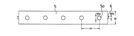
図5は騒音低減装置を平面上に展開した状態を示すものである。図5に示すように、コーティング部分5aの幅Wsはバンド部材6の幅Wbに対して0.5Wb≦Ws≦1.5Wbの関係にすると良い。0.5Wb>Wsであるとバンド部材6と吸音材5との接合作業が困難になり、逆にWs>1.5Wbであると吸音効果が低下する要因となる。更に、コーティング部分5aを熱融着する部位はタイヤ周方向に間隔(ピッチ)をあけて配置し、その間隔Hを吸音材5の幅Wに対して0.2W≦H≦4Wの関係にすると良い。0.2W>Hであると熱融着時の作業性が低下し、逆にH>4Wであるとバンド部材6に対する吸音材5の接合状態が不安定になる。なお、コーティング部分5aを熱融着する部位は、必ずしも等間隔である必要はない。
FIG. 5 shows a state in which the noise reduction device is developed on a plane. As shown in FIG. 5, the width Ws of the
図6〜図9は騒音低減装置の変形例をそれぞれ平面上に展開した状態を示すものである。図6において、コーティング部分5aの平面視形状は四角形になっている。つまり、コーティング部分5aの平面視形状は特に限定されるものではなく、円形、四角形等の任意の形状にすることができる。また、図7に示すように、コーティング部分5aをタイヤ周方向に連続的に設けることも可能である。更に、図8及び図9に示すように、吸音材5を複数の分割片から構成し、これら分割片をバンド部材6の長手方向に沿って配置するようにしても良い。吸音材5の各分割片をバンド部材6に対して少なくとも2箇所で熱融着することが好ましい。
6 to 9 show states in which variations of the noise reduction device are developed on a plane, respectively. In FIG. 6, the plan view shape of the
従来例及び実施例の騒音低減装置をそれぞれ製作した。従来例の騒音低減装置は、帯状のウレタンフォーム(幅150mm×厚さ20mm)からなる吸音材をポリプロピレン製のバンド部材(幅20mm×厚さ2mm×タイヤ内周長)に接着剤を用いて固定し、そのバンド部材を環状に成形したものである。実施例の騒音低減装置は、帯状のウレタンフォーム(幅150mm×厚さ20mm)からなる吸音材に長さ方向に沿って約200mm間隔でポリプロピレンエマルションを含浸させてコーティング部分を形成し、超音波溶着機を用いてコーティング部分をポリプロピレン製のバンド部材(幅20mm×厚さ2mm×タイヤ内周長)に対して熱融着したものである。コーティング部分の総体積は吸音材の総体積の5%とした。
The noise reduction apparatus of the prior art example and an Example was each manufactured. The conventional noise reduction device fixes a sound absorbing material made of a band-like urethane foam (width 150 mm × thickness 20 mm) to a polypropylene band member (width 20 mm ×
これら従来例及び実施例の騒音低減装置をそれぞれタイヤサイズ215/55R16の空気入りタイヤに装着し、ドラム試験機にて内圧150kPa、速度80km/hの条件で走行し、吸音材に剥離が発生するまでの走行距離を測定した。その結果を表1に示す。評価結果は、従来例を100とする指数にて示した。この指数値が大きいほど耐久性が良好であることを意味する。
The noise reduction devices of these conventional examples and examples are mounted on pneumatic tires of tire size 215 / 55R16, respectively, and run on a drum testing machine under conditions of an internal pressure of 150 kPa and a speed of 80 km / h, and peeling occurs in the sound absorbing material. The distance traveled was measured. The results are shown in Table 1. The evaluation results are shown as an index with the conventional example being 100. The larger the index value, the better the durability.

この表1から判るように、実施例の騒音低減装置は、従来例に比べて耐久性が大幅に向上していた。 As can be seen from Table 1, the durability of the noise reduction device of the example was significantly improved compared to the conventional example.
1 トレッド部
2 ビード部
3 サイドウォール部
4 騒音低減装置
5 吸音材
5a コーティング部分
6 バンド部材
11 超音波溶着機の加振用ホーン
DESCRIPTION OF
Claims (14)
Priority Applications (1)
| Application Number | Priority Date | Filing Date | Title |
|---|---|---|---|
| JP2005082368A JP4628834B2 (en) | 2005-03-22 | 2005-03-22 | Noise reduction device, manufacturing method thereof, and pneumatic tire provided with noise reduction device |
Applications Claiming Priority (1)
| Application Number | Priority Date | Filing Date | Title |
|---|---|---|---|
| JP2005082368A JP4628834B2 (en) | 2005-03-22 | 2005-03-22 | Noise reduction device, manufacturing method thereof, and pneumatic tire provided with noise reduction device |
Publications (2)
| Publication Number | Publication Date |
|---|---|
| JP2006264406A true JP2006264406A (en) | 2006-10-05 |
| JP4628834B2 JP4628834B2 (en) | 2011-02-09 |
Family
ID=37200828
Family Applications (1)
| Application Number | Title | Priority Date | Filing Date |
|---|---|---|---|
| JP2005082368A Expired - Fee Related JP4628834B2 (en) | 2005-03-22 | 2005-03-22 | Noise reduction device, manufacturing method thereof, and pneumatic tire provided with noise reduction device |
Country Status (1)
| Country | Link |
|---|---|
| JP (1) | JP4628834B2 (en) |
Cited By (1)
| Publication number | Priority date | Publication date | Assignee | Title |
|---|---|---|---|---|
| JP2010000914A (en) * | 2008-06-20 | 2010-01-07 | Yokohama Rubber Co Ltd:The | Tire noise reduction device and pneumatic tire having the same mounted thereon |
Citations (7)
| Publication number | Priority date | Publication date | Assignee | Title |
|---|---|---|---|---|
| JPH0986113A (en) * | 1995-09-28 | 1997-03-31 | Tokai Rubber Ind Ltd | Wheel acoustic material |
| JPH0986112A (en) * | 1995-09-28 | 1997-03-31 | Tokai Rubber Ind Ltd | Wheel acoustic material |
| JP2004168212A (en) * | 2002-11-21 | 2004-06-17 | Tokai Rubber Ind Ltd | Noise absorbing device for wheel and wheel with noise absorbing device |
| WO2005012005A1 (en) * | 2003-08-04 | 2005-02-10 | The Yokohama Rubber Co., Ltd. | Low noise pneumatic tire |
| WO2005012007A1 (en) * | 2003-08-04 | 2005-02-10 | The Yokohama Rubber Co.,Ltd. | Low noise pneumatic tire |
| WO2005012008A1 (en) * | 2003-08-04 | 2005-02-10 | The Yokohama Rubber Co.,Ltd. | Low noise pneumatic tire |
| JP2005053319A (en) * | 2003-08-04 | 2005-03-03 | Yokohama Rubber Co Ltd:The | Pneumatic tire |
-
2005
- 2005-03-22 JP JP2005082368A patent/JP4628834B2/en not_active Expired - Fee Related
Patent Citations (7)
| Publication number | Priority date | Publication date | Assignee | Title |
|---|---|---|---|---|
| JPH0986113A (en) * | 1995-09-28 | 1997-03-31 | Tokai Rubber Ind Ltd | Wheel acoustic material |
| JPH0986112A (en) * | 1995-09-28 | 1997-03-31 | Tokai Rubber Ind Ltd | Wheel acoustic material |
| JP2004168212A (en) * | 2002-11-21 | 2004-06-17 | Tokai Rubber Ind Ltd | Noise absorbing device for wheel and wheel with noise absorbing device |
| WO2005012005A1 (en) * | 2003-08-04 | 2005-02-10 | The Yokohama Rubber Co., Ltd. | Low noise pneumatic tire |
| WO2005012007A1 (en) * | 2003-08-04 | 2005-02-10 | The Yokohama Rubber Co.,Ltd. | Low noise pneumatic tire |
| WO2005012008A1 (en) * | 2003-08-04 | 2005-02-10 | The Yokohama Rubber Co.,Ltd. | Low noise pneumatic tire |
| JP2005053319A (en) * | 2003-08-04 | 2005-03-03 | Yokohama Rubber Co Ltd:The | Pneumatic tire |
Cited By (2)
| Publication number | Priority date | Publication date | Assignee | Title |
|---|---|---|---|---|
| JP2010000914A (en) * | 2008-06-20 | 2010-01-07 | Yokohama Rubber Co Ltd:The | Tire noise reduction device and pneumatic tire having the same mounted thereon |
| JP4525800B2 (en) * | 2008-06-20 | 2010-08-18 | 横浜ゴム株式会社 | Tire noise reduction device and pneumatic tire equipped with the same |
Also Published As
| Publication number | Publication date |
|---|---|
| JP4628834B2 (en) | 2011-02-09 |
Similar Documents
| Publication | Publication Date | Title |
|---|---|---|
| JP4175479B2 (en) | Noise reduction device, manufacturing method thereof, and pneumatic tire provided with noise reduction device | |
| JP4175480B2 (en) | Noise reduction device, manufacturing method thereof, and pneumatic tire provided with noise reduction device | |
| CN107444030B (en) | The manufacturing method of pneumatic tire and pneumatic tire | |
| JP6510875B2 (en) | tire | |
| JP6428046B2 (en) | Noise reduction device and pneumatic tire provided with the same | |
| CN111344142B (en) | Pneumatic tire with noise damper | |
| JP6432211B2 (en) | Noise reduction device and pneumatic tire provided with the same | |
| JP4628834B2 (en) | Noise reduction device, manufacturing method thereof, and pneumatic tire provided with noise reduction device | |
| JP5760424B2 (en) | Tire noise reduction device | |
| TW200911571A (en) | Apparatus and method for removably securing tyre pressure monitoring sensor to a tyre | |
| JP6690362B2 (en) | Tire noise reduction device and pneumatic tire including the same | |
| JP2009137568A (en) | Tire | |
| JP5565558B2 (en) | Tire internal equipment support, tire and tire assembly | |
| JP2007099048A (en) | Pedestal for mounting electronic component and tire with pedestal | |
| JP6561727B2 (en) | Noise reduction device and pneumatic tire provided with the same | |
| JP4561292B2 (en) | Pneumatic tire | |
| JP2010111074A (en) | Ultrasonic bonding device and method of manufacturing tire | |
| JP6349927B2 (en) | Tire noise reduction device and pneumatic tire | |
| JP5249676B2 (en) | Pneumatic tire with sound control | |
| JP2017159794A (en) | Functional component device and tire comprising the functional component device | |
| JP7140779B2 (en) | Method for fixing tire and porous body | |
| JP6135592B2 (en) | Engine cover | |
| JP2005219592A (en) | Low load noise wheel | |
| JP2004306671A (en) | Manufacturing method of steering wheel and steering wheel | |
| JP6674772B2 (en) | Pneumatic tire, pneumatic tire and rim assembly, and rim |
Legal Events
| Date | Code | Title | Description |
|---|---|---|---|
| A621 | Written request for application examination |
Free format text: JAPANESE INTERMEDIATE CODE: A621 Effective date: 20080311 |
|
| A977 | Report on retrieval |
Free format text: JAPANESE INTERMEDIATE CODE: A971007 Effective date: 20101007 |
|
| TRDD | Decision of grant or rejection written | ||
| A01 | Written decision to grant a patent or to grant a registration (utility model) |
Free format text: JAPANESE INTERMEDIATE CODE: A01 Effective date: 20101102 |
|
| A01 | Written decision to grant a patent or to grant a registration (utility model) |
Free format text: JAPANESE INTERMEDIATE CODE: A01 |
|
| A61 | First payment of annual fees (during grant procedure) |
Free format text: JAPANESE INTERMEDIATE CODE: A61 Effective date: 20101110 |
|
| FPAY | Renewal fee payment (event date is renewal date of database) |
Free format text: PAYMENT UNTIL: 20131119 Year of fee payment: 3 |
|
| R150 | Certificate of patent or registration of utility model |
Ref document number: 4628834 Country of ref document: JP Free format text: JAPANESE INTERMEDIATE CODE: R150 Free format text: JAPANESE INTERMEDIATE CODE: R150 |
|
| R250 | Receipt of annual fees |
Free format text: JAPANESE INTERMEDIATE CODE: R250 |
|
| R250 | Receipt of annual fees |
Free format text: JAPANESE INTERMEDIATE CODE: R250 |
|
| R250 | Receipt of annual fees |
Free format text: JAPANESE INTERMEDIATE CODE: R250 |
|
| R250 | Receipt of annual fees |
Free format text: JAPANESE INTERMEDIATE CODE: R250 |
|
| R250 | Receipt of annual fees |
Free format text: JAPANESE INTERMEDIATE CODE: R250 |
|
| R250 | Receipt of annual fees |
Free format text: JAPANESE INTERMEDIATE CODE: R250 |
|
| R250 | Receipt of annual fees |
Free format text: JAPANESE INTERMEDIATE CODE: R250 |
|
| LAPS | Cancellation because of no payment of annual fees |