JP2006238520A - Load drive unit - Google Patents
Load drive unit Download PDFInfo
- Publication number
- JP2006238520A JP2006238520A JP2005045546A JP2005045546A JP2006238520A JP 2006238520 A JP2006238520 A JP 2006238520A JP 2005045546 A JP2005045546 A JP 2005045546A JP 2005045546 A JP2005045546 A JP 2005045546A JP 2006238520 A JP2006238520 A JP 2006238520A
- Authority
- JP
- Japan
- Prior art keywords
- power
- load
- capacitor
- voltage
- converter
- Prior art date
- Legal status (The legal status is an assumption and is not a legal conclusion. Google has not performed a legal analysis and makes no representation as to the accuracy of the status listed.)
- Granted
Links
Images


Landscapes
- Rectifiers (AREA)
- Control Of Ac Motors In General (AREA)
- Inverter Devices (AREA)
Abstract
Description
本発明は、クレーン等の昇降機を駆動するに好適な負荷駆動装置に関する。 The present invention relates to a load driving device suitable for driving an elevator such as a crane.
クレーン等の昇降機を駆動する負荷駆動装置は、一般に交流電源を直流電力に変換する直流・交流コンバータと、この直流・交流コンバータから出力される直流電力を、電圧および周波数が制御された交流に変換して電動機を駆動するインバータとを備えて構成される。また上記直流・交流コンバータから出力される直流電力をコンデンサ(蓄電器)に蓄え、このコンデンサに蓄積された電力を用いて前記インバータを力行駆動すると共に、前記電動機を介して得られる回生電力を上記コンデンサに蓄積して前記インバータの駆動に再利用することも提唱されている(例えば特許文献1を参照)。 Load drive devices that drive cranes and other elevators generally convert a DC / AC converter that converts AC power into DC power, and the DC power output from this DC / AC converter is converted to AC with controlled voltage and frequency. And an inverter for driving the electric motor. Further, the DC power output from the DC / AC converter is stored in a capacitor (capacitor), and the inverter is power-driven using the power stored in the capacitor, and the regenerative power obtained via the motor is supplied to the capacitor. It is also proposed to accumulate the data in the inverter and reuse it for driving the inverter (see, for example, Patent Document 1).
また最近、小型で大容量の電気二重層コンデンサが注目されており、上述した負荷駆動装置における電力蓄積用のコンデンサとして電気二重層コンデンサを用いることが考えられている。
ところで上述したクレーン等の昇降機における電動機の駆動には多大な電力(力行エネルギ)を要し、また電動機から得られる回生電力(回生エネルギ)も大きい。従ってその電力(電力エネルギ)を如何にして効率的に電気二重層コンデンサに入出力するかが問題となる。しかも電気二重層コンデンサに蓄積した電力エネルギを有効に活用し、また電動機から得られた回生電力を無駄なく回収して再利用するには、電動機の運転条件に応じて電気二重層コンデンサに蓄積した電力量を適正に保つことが必要である。 By the way, driving the electric motor in the elevator such as the crane described above requires a large amount of electric power (powering energy), and the regenerative electric power (regenerative energy) obtained from the electric motor is large. Therefore, how to efficiently input / output the electric power (power energy) to / from the electric double layer capacitor becomes a problem. Moreover, in order to effectively use the energy stored in the electric double layer capacitor and to recover and reuse the regenerative power obtained from the motor without waste, it was stored in the electric double layer capacitor according to the operating conditions of the motor. It is necessary to keep the amount of power appropriate.
具体的には電動機の力行運転が想定される場合には、その力行駆動に要する電力エネルギを予め電気二重層コンデンサに蓄えておくことが必要である。逆に電動機の回生運転が予想される場合には、その回生電力を電気二重層コンデンサに確実に蓄積し得るように該電気二重層コンデンサに蓄積されている電力量を低く抑え、その充電可能な容量に余裕を持たせておくことが必要である。 Specifically, when a power running operation of the electric motor is assumed, it is necessary to store power energy required for the power running drive in advance in an electric double layer capacitor. Conversely, when regenerative operation of the motor is expected, the amount of power stored in the electric double layer capacitor can be kept low so that the regenerative power can be reliably stored in the electric double layer capacitor, and the electric charge can be charged. It is necessary to provide a sufficient capacity.
本発明はこのような事情を考慮してなされたもので、その目的は、負荷の運転条件に応じてコンデンサに蓄えておく電力量を適正に制御することができ、これによって上記コンデンサを介する負荷の駆動と負荷から回収される回生電力の蓄積とを効率的に行い得るようにした負荷駆動装置を提供することにある。 The present invention has been made in view of such circumstances, and its purpose is to appropriately control the amount of power stored in the capacitor in accordance with the operating condition of the load, and thereby the load through the capacitor. It is an object of the present invention to provide a load driving device that can efficiently perform the driving of the motor and accumulation of regenerative power recovered from the load.
上述した目的を達成するべく本発明に係る負荷駆動装置は、外部電源から与えられる交流電力を直流電力に変換する機能、および直流電力を交流電力に変換して前記外部電源に回生する機能を備えた交流・直流コンバータと、この交流・直流コンバータから出力される直流電力を蓄積するコンデンサと、このコンデンサに蓄積された直流電力および/または前記交流・直流コンバータから出力された直流電力を、電圧および周波数が制御された交流電力に変換して負荷を駆動すると共に、上記負荷に生じた回生電力を回収して前記電気二重層コンデンサに蓄積するインバータとを具備したものであって、
特に前記交流・直流コンバータの作動を制御する制御器は、
<a> 前記負荷の状態量に応じて該負荷の力行駆動に要する電力量または前記負荷から回生される電力量を予測し、予測した電力量に基づいて前記交流・直流コンバータに対する直流電圧設定値を決定する制御条件設定手段と、
<b> 前記交流・直流コンバータの直流側での直流電圧検出値が上記直流電圧設定値よりも小さいときには、予め設定した電流制限値の範囲内で前記外部電源からの電力供給運転を行わせる第1の制御手段と、
<c> 前記直流電圧検出値が前記直流電圧設定値よりも大きいときには、前記電流制限値の範囲内で前記外部電源への電力回生運転を行わせる第2の制御手段とを備えることを特徴としている。
In order to achieve the above-described object, a load driving device according to the present invention has a function of converting AC power supplied from an external power source into DC power, and a function of converting DC power into AC power and regenerating the external power source. AC / DC converter, a capacitor for storing DC power output from the AC / DC converter, DC power stored in the capacitor and / or DC power output from the AC / DC converter, An inverter that converts AC power with a controlled frequency to drive a load, collects regenerative power generated in the load, and accumulates it in the electric double layer capacitor;
In particular, the controller that controls the operation of the AC / DC converter is:
<a> Predicts the amount of power required for powering driving of the load or the amount of power regenerated from the load according to the state quantity of the load, and sets the DC voltage setting value for the AC / DC converter based on the predicted amount of power Control condition setting means for determining
<b> When the DC voltage detection value on the DC side of the AC / DC converter is smaller than the DC voltage set value, the power supply operation from the external power source is performed within a preset current limit value range. 1 control means;
<c> When the DC voltage detection value is larger than the DC voltage set value, the second control means for performing a power regeneration operation to the external power source within the range of the current limit value. Yes.
好ましくは請求項2に記載するように前記電流値制限値は、前記交流・直流コンバータの最大許容電流以下の値として予め設定される。また請求項3に記載するように前記負荷は、昇降機を駆動する電動機からなり、前記負荷の状態量は上記昇降機により昇降される物体の重量とその移動高さ情報として与えられる。具体的には前記負荷の状態量は、荷物を昇降させる昇降ゲージ(吊具)の重量と荷物の重量、および昇降ゲージ(吊具)の位置として、或いはクレーンにおける吊り荷の重量と吊り上げ高さの情報として与えられる。 Preferably, the current value limit value is preset as a value equal to or less than a maximum allowable current of the AC / DC converter. According to a third aspect of the present invention, the load comprises an electric motor that drives an elevator, and the state quantity of the load is given as information on the weight of the object that is raised and lowered by the elevator and its moving height. Specifically, the state quantity of the load includes the weight of the lifting gauge (hanging tool) for lifting and lowering the load and the weight of the load, and the position of the lifting gauge (hanging tool), or the weight of the lifting load and the lifting height in the crane. Given as information.
また前記直流電圧設定値は、請求項4に記載するように予測した電力量が、例えば荷物を持ち上げるときのような負荷の力行を示す場合には高く設定され、逆に吊り上げた荷物の重量を利用して荷物を降ろすような負荷の回生を示す場合には低く設定される。 The DC voltage set value is set to be high when the predicted amount of electric power as described in claim 4 indicates powering of a load such as when lifting a load, and the weight of the lifted load is reversed. It is set low when it indicates a regeneration of a load that uses the load to unload.
上述したように構成された負荷駆動装置によれば、交流・直流コンバータの作動を制御する制御器は、負荷の状態量に応じて該負荷の力行駆動に要する電力量または前記負荷から回生される電力量を予測し、予測した電力量に基づいて前記コンデンサに蓄積すべき電力量を制御する為の前記交流・直流コンバータに対する直流電圧設定値を決定する。そして交流・直流コンバータの直流側での直流電圧検出値、つまりコンデンサの充電電圧(端子電圧)が上記直流電圧設定値よりも大きいか、或いは小さいかに応じて前記交流・直流コンバータの作動を制御する。具体的にはコンデンサの充電電圧が上記直流電圧設定値よりも小さいときには、前記交流・直流コンバータに外部電源からコンデンサに電力供給する電力供給運転を行わせ、逆にコンデンサの充電電圧が上記直流電圧設定値よりも大きいときには、コンデンサに蓄積されている電力を外部電源に戻す電力回生運転を行わせることになる。 According to the load driving device configured as described above, the controller that controls the operation of the AC / DC converter is regenerated from the amount of power required for powering driving of the load or the load according to the state quantity of the load. A power amount is predicted, and a DC voltage setting value for the AC / DC converter for controlling the power amount to be stored in the capacitor is determined based on the predicted power amount. The operation of the AC / DC converter is controlled depending on whether the DC voltage detection value on the DC side of the AC / DC converter, that is, the charging voltage (terminal voltage) of the capacitor is larger or smaller than the DC voltage setting value. To do. Specifically, when the charging voltage of the capacitor is smaller than the DC voltage set value, the AC / DC converter is operated to supply power from the external power source to the capacitor, and conversely, the charging voltage of the capacitor is the DC voltage. When the value is larger than the set value, the electric power regeneration operation for returning the electric power stored in the capacitor to the external power source is performed.
従って負荷の状態に応じて予測される前記負荷の駆動電力量または前記負荷からの回生電力量を見込んで前記コンデンサの充電量を適正に制御することが可能となる。従ってコンデンサを介して負荷を安定に駆動し、また負荷から得られる回生電力を前記コンデンサに確実に蓄積することが可能となる。しかもコンデンサの充電量に応じて前記交流・直流コンバータの電力供給運転と電力回生運転とを、予め設定した電流制限値の範囲でそれぞれ実行するので、コンデンサに過度な負担を掛けることなしに上記コンデンサの充電量を適正化することができる。 Therefore, it is possible to appropriately control the charge amount of the capacitor in anticipation of the drive power amount of the load predicted according to the load state or the regenerative power amount from the load. Therefore, it is possible to stably drive the load via the capacitor and to reliably store the regenerative power obtained from the load in the capacitor. In addition, since the power supply operation and the power regeneration operation of the AC / DC converter are respectively performed within the range of preset current limit values in accordance with the charge amount of the capacitor, the above capacitor can be used without imposing an excessive burden on the capacitor. The amount of charge can be optimized.
以下、図面を参照して本発明の一実施形態に係る負荷駆動装置について説明する。
この負荷駆動装置は、例えば物品(荷物)を吊り上げて昇降させるクレーンや、物品を載置する昇降ステージを上下動させるリフタ等における駆動用の誘導電動機(モータ)を負荷とし、外部電源から与えられる交流電力(例えば200Vの動力系三相交流電力)を用いて上記電動機を駆動するものである。特に負荷駆動装置は、基本的には交流・直流コンバータを用いて交流電力から直流電力を生成し、更にこの直流電力からインバータを用いて電圧および周波数が制御された交流電力を生成して電動機(負荷)を駆動するように構成される。
Hereinafter, a load driving device according to an embodiment of the present invention will be described with reference to the drawings.
This load driving device is supplied from an external power source, for example, with a driving induction motor (motor) in a crane that lifts and lowers an article (luggage) and a lifter that moves an elevating stage for placing the article up and down. The electric motor is driven using AC power (for example, 200V power system three-phase AC power). In particular, the load driving device basically generates DC power from AC power using an AC / DC converter, and further generates AC power whose voltage and frequency are controlled from this DC power using an inverter. Load).
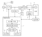
即ち、本発明に係る負荷駆動装置は、図1にその概略的なブロック構成を示すように外部電源1から与えられる交流電力を直流電力に変換する交流・直流コンバータ2と、この交流・直流コンバータ2から出力される直流電力を蓄積するコンデンサ3を備える。このコンデンサ3は、例えば小型で充電容量の大きい電気二重層コンデンサからなる。更に負荷駆動装置は、上記コンデンサ3に蓄積された直流電力および/または前記交流・直流コンバータ1から出力される直流電力から電圧および周波数を制御した交流電力を生成して負荷(電動機)4を駆動するインバータ5を備える。またこのインバータ5は、前記負荷(電動機)4から回生電力が得られるとき、その回生電力を直流電力に変換して回収して前記コンデンサ3に蓄積する機能を備えたものである。
That is, the load driving device according to the present invention includes an AC /
尚、前記インバータ5は、負荷4の駆動状態に応じて負荷制御器6によりその動作が制御される。特に負荷制御器6は、負荷4の駆動に要する電力が正(+)である場合には、コンデンサ3に蓄積された電力および/または交流・直流コンバータ2から得られる電力を用いて負荷4を力行駆動し、また負荷4の駆動に要する電力が負(−)であり、負荷4を介して電力が回生される場合には、その回生電力を回収して前記コンデンサ3を充電するものとなっている。
The operation of the inverter 5 is controlled by a
また前記交流・直流コンバータ2は、その直流側の電圧、具体的にはコンデンサ3の充電電圧(端子電圧)に応じて電源制御器7によりその動作が制御される。特に電源制御器7は、負荷5の状態に応じて前記インバータ3による上記負荷5の駆動に要する電力量、或いは負荷5から得られる回生電力量を予測し(予測機能7a)、この予測した電力量に従って前記コンデンサ3の充電量(蓄積電力量)を制御する為の直流電圧設定設定値Vfixを設定している(電圧設定機能7b)。そしてその直流系にて検出されるコンデンサ3の充電電圧Vsenc上述した直流電圧設定設定値Vfixとを比較し、その比較結果に応じて前記交流・直流コンバータ2を電力供給運転、または電力回生運転させることでコンデンサ3の充電量を制御するものとなっている。
The operation of the AC /
具体的にはコンデンサ3の充電量Uは、その容量をCとしたとき[U=(1/2)CV2]として示され、図2に示すように充電電圧Vの2乗に比例して変化する。換言すればコンデンサ3に加える電圧(印加電圧)がその端子電圧よりも高い場合には、コンデンサ3に蓄積し得る電気容量(電気エネルギ量)に余裕があるので、その端子電圧が印加電圧に達するまでコンデンサ3に対する充電が行われる。これに対してコンデンサ3に加える電圧(印加電圧)がその端子電圧よりも低い場合には、コンデンサ3の蓄えられている電気容量(電気エネルギ量)が過剰なので、その端子電圧が印加電圧に達するまでコンデンサ3に対する放電が行われる。
Specifically, the charge amount U of the
電源制御器7は、上述したようにコンデンサ3における充電量が該コンデンサ3に加える直流電圧の2乗に比例して変化することに着目し、負荷4の駆動に要する電力量(要求電力)をコンデンサ3に蓄積しておくべく、或いは負荷4から得られる電力量(回生電力量)を前記コンデンサ3に確実に蓄積するべく、前述したように交流・直流コンバータ2の出力電圧を直流電圧設定値Vfixとして設定している。
The
即ち、負荷4がクレーン等の昇降機である場合、荷物を吊り下げるワイヤを巻き上げて上記荷物を持ち上げるに際しては、その電動機の運転に力行電力を必要とする。そしてその駆動に要する電力Udrivは、例えば荷物の重量Wと、クレーンの最大吊り上げ高さHmaxおよび現在の高さ位置Hnowの各情報から
Udriv=K1・W・(Hmax−Hnow)
として予測(計算)することができる。但し、上記K1は力行運転時の機械効率および電気効率に依存する係数である。また逆に荷物を降ろす場合には、荷物の重量Wに逆らってワイヤを巻き戻す際に電動機に回生電力が生起される。そしてその回生電力Ubackは、クレーンの最大吊り下げ高さをHminとして
Uback=K2・W・(Hnow−Hmin)
として予測(計算)することができる。但し、上記K2は回生運転時の機械効率および電気効率に依存する係数である。
That is, when the load 4 is an elevator such as a crane, when the load is lifted by winding a wire for hanging the load, a power running power is required for driving the motor. The electric power Udriv required to drive the vehicle is calculated from, for example, the weight W of the load, the maximum lifting height Hmax of the crane, and the current height position Hnow.
Can be predicted (calculated) as However, K1 is a coefficient depending on the mechanical efficiency and the electric efficiency during the power running operation. Conversely, when unloading a load, regenerative power is generated in the motor when the wire is rewound against the weight W of the load. And the regenerative power Uback is the maximum suspension height of the crane as Hmin. Uback = K2W (Hnow-Hmin)
Can be predicted (calculated) as However, K2 is a coefficient depending on the mechanical efficiency and the electric efficiency during the regenerative operation.
故に荷物の重量Wと、クレーンの状態である現在の高さ位置Hnowの各情報をそれぞれ求めれば、重量Wの荷物を現在の高さHnowから高さHmaxまで持ち上げる上で必要となる力行電力Udriv、または上記荷物を現在の高さHnowから高さHminまで降ろす際に得られる回生電力Ubackをそれぞれ予測することが可能となる。従って荷物を持ち上げる場合、上記力行電力Udrivをコンデンサ3から得られるように、また荷物を降ろす場合には、上記回生電力Ubackを前記コンデンサ3に蓄積し得るように、予め前記コンデンサ3に蓄積する電力量を調整しておくべく、前記交流・直流コンバータ2の出力電圧を直流電圧設定値Vfixとして設定している。
Therefore, if each information of the weight W of the load and the current height position Hnow which is the state of the crane is obtained, the power running power Udriv necessary for lifting the load of weight W from the current height Hnow to the height Hmax. Alternatively, it is possible to predict the regenerative power Uback obtained when the baggage is lowered from the current height Hnow to the height Hmin. Therefore, when lifting a load, the power running power Udriv can be obtained from the
その上で、その直流系において検出されるコンデンサ3の充電電圧(端子電圧)Vsencと上記直流電圧設定値Vfixとを比較し(判定機能7c)、その判定結果に応じて前記交流・直流コンバータ2を電力供給運転(電力供給運転機能7d)し、または電力回生運転(電力回生運転機能7e)させるものとなっている。特にコンデンサ3の充電電圧(端子電圧)Vsencが上記直流電圧設定値Vfixよりも低い場合には、図2に示すように上記充電電圧Vsencが直流電圧設定値Vfixに達するまで電力供給運転を実行させ、逆にコンデンサ3の充電電圧Vsencが上記直流電圧設定値Vfixよりも高い場合には、その充電電圧Vsencが直流電圧設定値Vfixに達するまで電力回生運転を実行させている。
Then, the charging voltage (terminal voltage) Vsenc of the
この結果、負荷4の力行駆動に要する電力をコンデンサ3に予め蓄積するように、或いはコンデンサ3における充電余裕容量が前記負荷4から得られる回生電力を上回るように、前記コンデンサ3の充電容量が調整される。尚、交流・直流コンバータ2の電力供給運転とは、外部電源1から供給される交流電力を直流電力に変換してコンデンサ3を充電する動作であり、電力回生運転とは、コンデンサ3に蓄えられている直流電力を交流電力に変換して外部電源1に戻す(逆供給する)動作である。またこれらの電力供給運転および電力回生運転は、一定の電流値制限の下で行われる。
As a result, the charging capacity of the
具体的には前記電源制御部7においては、図3にその概略的な制御手順を示すように先ずその運転条件が成立しているか否かを判定する〈ステップS1〉。そして運転条件が成立している場合には、初期設定処理として交流・直流コンバータ2が出力するべく前述した予測電力量に基づいて設定した直流電圧設定値Vfixを取り込むと共に、図示しないセンサ(電圧計)にて検出される直流系の電圧(コンデンサ3の充電電圧)を直流電圧検出値Vsencを取り込む〈ステップS2〉。この際、交流・直流コンバータ2における電力供給時の電流制限値Isupと、電力回生時の電流制限値Iregとをそれぞれ取り込むと共に、更に交流・直流コンバータ2が制御可能な出力電圧の範囲を示す直流電圧上限値Vmaxと直流電圧下限値Vminとをそれぞれ取り込む。尚、上記電力供給時および電力回生時の各電流制限値Isup,Iregは、交流・直流コンバータ2の仕様によって定まる許容最大電流の範囲で任意に設定すれば良いものである。
Specifically, the power
しかる後、電源制御部7においては、先ず負荷の状態に応じて設定した前記直流電圧設定値Vfixと直流電圧検出値Vsencとを比較し、コンデンサ3に所要とする電力量が蓄積されているか否かを判定する〈ステップS3〉。そして直流電圧検出値Vsencが直流電圧設定値Vfixと等しく、コンデンサ3に所要とする電力量が蓄積されていることが確認された場合には、交流・直流コンバータ2に対する制御を停止して元に戻る〈ステップS4〉。
Thereafter, the power
これに対して直流電圧設定値Vfixと直流電圧検出値Vsencとが異なる場合に、直流電圧設定値Vfixよりも直流電圧検出値Vsencが高いか否かを判定する〈ステップS5〉。そして直流電圧設定値Vfixよりも直流電圧検出値Vsencが高い場合には、コンデンサ3に所望とする電力量以上の電力が蓄えられていることが判定されるので、前記交流・直流コンバータ2を電力回生運転する。この際、上記直流電圧検出値Vsencが直流電圧上限値Vmaxを上回っているか否かを判定し〈ステップS6〉、直流電圧検出値Vsencが高い場合には、コンデンサ3に過剰に蓄積されている電力エネルギを速やかに外部電源1に回収するべく、交流・直流コンバータ2を前述した電流制限を解除して電力回生運転を行う〈ステップS7〉。しかし直流電圧検出値Vsencが低い場合には、前記コンデンサ3の充電電力を徐々に外部電源1に回収するべく、前記交流・直流コンバータ2を前述した電流制限値Iregによる電流制限の下で一定電流で電力回生運転する〈ステップS8〉。
On the other hand, if the DC voltage setting value Vfix and the DC voltage detection value Vsenc are different, it is determined whether or not the DC voltage detection value Vsenc is higher than the DC voltage setting value Vfix <step S5>. When the DC voltage detection value Vsenc is higher than the DC voltage setting value Vfix, it is determined that the
これに対して直流電圧設定値Vfixよりも直流電圧検出値Vsencが低い場合には、コンデンサ3に所望とする電力量の電力が蓄えられてないことが判定されるので、前記交流・直流コンバータ2を電力供給運転する。この際、上記直流電圧検出値Vsencが直流電圧下限値Vminに満たないか否かを判定し〈ステップS9〉、直流電圧検出値Vsencが直流電圧下限値Vminに満たない場合には、コンデンサ3の充電量を前記交流・直量コンバータ2の動作特性を保証する範囲まで速やかに充電するべく、交流・直流コンバータ2を前述した電流制限を解除して電力供給運転を行う〈ステップS10〉。しかし直流電圧検出値Vsencが直流電圧下限値Vminを上回っている場合には、前記コンデンサ3を所望とする充電量まで徐々に充電するべく、前記交流・直流コンバータ2を前述した電流制限値Isupによる電流制限の下で一定電流で電力供給運転する〈ステップS11〉。
On the other hand, when the DC voltage detection value Vsenc is lower than the DC voltage setting value Vfix, it is determined that the desired amount of electric power is not stored in the
即ち、コンデンサ3の充電電圧である直流系での直流電圧検出値Vsencが、交流・直流コンバータ2によりコンデンサ3の充電量を制御し得る直流電圧上限値Vmaxと直流電圧下限値Vminの範囲内にあるときには、コンデンサ3の充電量を制御する直流電圧設定値Vfixとの電圧関係に応じて、交流・直流コンバータ2を前述した電流制限条件の下で電力供給運転、または電力回生運転させてコンデンサ3の充電量を一定化制御する。しかし直流電圧検出値Vsencが直流電圧上限値Vmaxを越え、コンデンサ3の充電量が過剰である場合には、交流・直流コンバータ2を強制的に電力回生運転して過剰な電力エネルギを外部電源1に回生させ、また直流電圧検出値Vsencが直流電圧下限値Vminに満たない場合には、前記交流・直流コンバータ2が制御不可能な電圧に前記コンデンサ3の電圧(充電量)が低下することを防ぐべく前記交流・直流コンバータ2を強制的に電力供給運転する。
That is, the DC voltage detection value Vsenc in the DC system that is the charging voltage of the
かくしてこのような交流・直流コンバータ2の運転制御によれば、コンデンサ3に蓄積する電力量を、負荷4の駆動に要する電力量、および負荷4から得られる回生電力量を見込んで、予め調整することができる。従ってコンデンサ3に蓄積した電力を用いて負荷4を力行駆動し、また負荷4から回生電力が得られる場合には、その回生電力をコンデンサ3に確実に蓄積することができる。そして負荷駆動装置による負荷4の駆動によって消費される電力を、予め定電流供給または定電力供給してコンデンサ3の充電量を最適化し、またコンデンサ3に蓄積された余剰な電力を外部電源1に効率的に回生することが可能となる。従って負荷駆動装置としての消費電力量を効果的に抑えることが可能となる等の効果が奏せられる。
Thus, according to the operation control of the AC /
尚、本発明は上述した実施形態に限定されるものではない。例えば工場等に設けられる天井クレーンにおいては、専ら、荷物を持ち上げて別の場所に移動した後、その場所に上記荷物を降ろす運転が基本となるので、荷物の持ち上げに要する力行電力量と、荷物の降ろし運転時に得られる回生電力量とをそれぞれ予測し、負荷4に対して入出力する力行電力量・回生電力量を勘案して前記コンデンサ3に蓄積しておくべき電力量を決定して前記直流電圧設定値Vfixを設定するようにすれば良い。
The present invention is not limited to the embodiment described above. For example, in an overhead crane installed in a factory, etc., the basic operation is to lift the load, move it to another location, and then drop the load to that location. The amount of regenerative electric power obtained at the time of the lowering operation is predicted, and the amount of power to be stored in the
またここではクレーンやリフタ等の昇降機の駆動を例に説明したが、負荷4から回生電力が得られるものであれば同様に適用することができる。具体的には負荷4を加減速し、加速時に力行エネルギを消費し、減速時に回生エネルギを回収し得るような負荷の駆動に同様に用いることができる。また昇降機の具体例としては、港湾設備におけるコンテナ移送(搬送)用のクレーン、ビル建設に用いられるジブクライミングクレーン、自動倉庫におけるスタッカクレーン、更には機械式立体駐車場におけるリフタ等を挙げることができる。 Moreover, although driving | operation of elevators, such as a crane and a lifter, was demonstrated here as an example, if regenerative electric power is obtained from the load 4, it can apply similarly. Specifically, the load 4 can be accelerated and decelerated, powering energy can be consumed during acceleration, and the drive can be similarly used for driving a load that can recover regenerative energy during deceleration. Specific examples of elevators include container transfer (transport) cranes in port facilities, jib climbing cranes used in building construction, stacker cranes in automatic warehouses, and lifters in mechanical multilevel parking lots. .
また負荷4がリフタ等における昇降ステージを昇降するような場合には、昇降ステージの重量Wfixと、該昇降ステージに搭載される荷物の重量Wとをそれぞれ入力して、その昇降に必要な力行電力Uneedおよび回生電力Ubackを予測するようにすれば良い。この場合、荷物を搭載するか否かによって上記力行電力Uneedおよび回生電力Ubackが変化することになる。その他、本発明はその要旨を逸脱しない範囲で種々変形して実施することができる。 When the load 4 moves up and down the lift stage such as a lifter or the like, the weight Wfix of the lift stage and the weight W of the load mounted on the lift stage are respectively input, and the power running power necessary for the lift is input. Uneed and regenerative power Uback may be predicted. In this case, the power running power Uneded and the regenerative power Uback vary depending on whether or not a load is loaded. In addition, the present invention can be variously modified and implemented without departing from the scope of the invention.
1 外部電源
2 交流・直流コンバータ
3 コンデンサ(電気二重層コンデンサ)
4 負荷(電動機)
5 インバータ
6 負荷制御器
7 電源制御器
7a 予測機能
7b 電圧設定機能
7c 判定機能
7d 電力供給運転機能
7e 電力回生運転機能
1
4 Load (motor)
5
Claims (4)
この交流・直流コンバータから出力される直流電力を蓄積するコンデンサと、
このコンデンサに蓄積された直流電力および/または前記交流・直流コンバータから出力された直流電力を、電圧および周波数が制御された交流電力に変換して負荷を駆動すると共に、上記負荷に生じた回生電力を回収して前記コンデンサに蓄積するインバータとを具備し、
前記交流・直流コンバータの作動を制御する制御器は、
前記負荷の状態量に応じて該負荷の力行駆動に要する電力量または前記負荷から回生される電力量を予測し、予測した電力量に基づいて前記交流・直流コンバータに対する直流電圧設定値を決定する制御条件設定手段と、
前記交流・直流コンバータの直流側での直流電圧検出値が上記直流電圧設定値よりも小さいときには、予め設定した電流制限値の範囲内で前記外部電源からの電力供給運転を行わせる第1の制御手段と、
前記直流電圧検出値が前記直流電圧設定値よりも大きいときには、前記電流制限値の範囲内で前記外部電源への電力回生運転を行わせる第2の制御手段と
を備えることを特徴とする負荷駆動装置。 An AC / DC converter having a function of converting AC power supplied from an external power source into DC power, and a function of converting DC power into AC power and regenerating the external power source;
A capacitor for storing the DC power output from the AC / DC converter;
The DC power stored in the capacitor and / or the DC power output from the AC / DC converter is converted to AC power with a controlled voltage and frequency to drive the load, and the regenerative power generated in the load An inverter that collects and accumulates in the capacitor,
The controller for controlling the operation of the AC / DC converter is:
The amount of power required for powering driving of the load or the amount of power regenerated from the load is predicted according to the state quantity of the load, and a DC voltage setting value for the AC / DC converter is determined based on the predicted amount of power. Control condition setting means;
When the DC voltage detection value on the DC side of the AC / DC converter is smaller than the DC voltage set value, the first control for performing the power supply operation from the external power source within a preset current limit value range. Means,
Load control, wherein the DC voltage detection value is greater than the DC voltage set value, and includes a second control means for performing a power regeneration operation to the external power source within the range of the current limit value. apparatus.
Priority Applications (1)
| Application Number | Priority Date | Filing Date | Title |
|---|---|---|---|
| JP2005045546A JP4634817B2 (en) | 2005-02-22 | 2005-02-22 | Load drive device |
Applications Claiming Priority (1)
| Application Number | Priority Date | Filing Date | Title |
|---|---|---|---|
| JP2005045546A JP4634817B2 (en) | 2005-02-22 | 2005-02-22 | Load drive device |
Publications (2)
| Publication Number | Publication Date |
|---|---|
| JP2006238520A true JP2006238520A (en) | 2006-09-07 |
| JP4634817B2 JP4634817B2 (en) | 2011-02-16 |
Family
ID=37045585
Family Applications (1)
| Application Number | Title | Priority Date | Filing Date |
|---|---|---|---|
| JP2005045546A Active JP4634817B2 (en) | 2005-02-22 | 2005-02-22 | Load drive device |
Country Status (1)
| Country | Link |
|---|---|
| JP (1) | JP4634817B2 (en) |
Cited By (10)
| Publication number | Priority date | Publication date | Assignee | Title |
|---|---|---|---|---|
| JP2007116787A (en) * | 2005-10-18 | 2007-05-10 | Power System:Kk | Charge/discharge controller for electric double-layer capacitor |
| JP2008306901A (en) * | 2007-06-11 | 2008-12-18 | Hitachi Industrial Equipment Systems Co Ltd | Inverter device |
| JP2009240108A (en) * | 2008-03-28 | 2009-10-15 | Kito Corp | Winch and regenerative electric power processing method for the same |
| JP2010260094A (en) * | 2009-05-11 | 2010-11-18 | Aida Eng Ltd | Method and apparatus for controlling servo press device |
| WO2011000492A1 (en) | 2009-06-30 | 2011-01-06 | Sew-Eurodrive Gmbh & Co. Kg | Inverter and method for operating a system having inverters |
| JP2012061563A (en) * | 2010-09-16 | 2012-03-29 | Denso Wave Inc | Robot system |
| JP2012509655A (en) * | 2008-11-21 | 2012-04-19 | オーチス エレベータ カンパニー | Operation of three-phase regenerative drive from mixed DC power and single-phase AC power |
| JP2012085512A (en) * | 2010-09-16 | 2012-04-26 | Fanuc Ltd | Motor drive apparatus using capacitor |
| JP5805353B1 (en) * | 2014-06-26 | 2015-11-04 | 三菱電機株式会社 | Positioning control device |
| CN112470388A (en) * | 2019-06-14 | 2021-03-09 | 东芝三菱电机产业系统株式会社 | Power conversion device and motor braking method |
Citations (5)
| Publication number | Priority date | Publication date | Assignee | Title |
|---|---|---|---|---|
| JPS62221014A (en) * | 1986-03-20 | 1987-09-29 | Sanyo Electric Co Ltd | Electric power converter |
| JPH052593U (en) * | 1991-06-25 | 1993-01-14 | 神鋼電機株式会社 | Power regeneration device |
| JPH11299290A (en) * | 1998-04-17 | 1999-10-29 | Hitachi Ltd | Ac motor drive system |
| JP2000236679A (en) * | 1999-02-16 | 2000-08-29 | Fuji Electric Co Ltd | Control method of power converter for motor control |
| JP2001171921A (en) * | 1999-12-22 | 2001-06-26 | Hitachi Ltd | Control device for plural elevator units |
-
2005
- 2005-02-22 JP JP2005045546A patent/JP4634817B2/en active Active
Patent Citations (5)
| Publication number | Priority date | Publication date | Assignee | Title |
|---|---|---|---|---|
| JPS62221014A (en) * | 1986-03-20 | 1987-09-29 | Sanyo Electric Co Ltd | Electric power converter |
| JPH052593U (en) * | 1991-06-25 | 1993-01-14 | 神鋼電機株式会社 | Power regeneration device |
| JPH11299290A (en) * | 1998-04-17 | 1999-10-29 | Hitachi Ltd | Ac motor drive system |
| JP2000236679A (en) * | 1999-02-16 | 2000-08-29 | Fuji Electric Co Ltd | Control method of power converter for motor control |
| JP2001171921A (en) * | 1999-12-22 | 2001-06-26 | Hitachi Ltd | Control device for plural elevator units |
Cited By (17)
| Publication number | Priority date | Publication date | Assignee | Title |
|---|---|---|---|---|
| JP2007116787A (en) * | 2005-10-18 | 2007-05-10 | Power System:Kk | Charge/discharge controller for electric double-layer capacitor |
| JP2008306901A (en) * | 2007-06-11 | 2008-12-18 | Hitachi Industrial Equipment Systems Co Ltd | Inverter device |
| JP2009240108A (en) * | 2008-03-28 | 2009-10-15 | Kito Corp | Winch and regenerative electric power processing method for the same |
| US8629637B2 (en) | 2008-11-21 | 2014-01-14 | Otis Elevator Company | Operation of a three-phase regenerative drive from mixed DC and single phase AC power sources |
| JP2012509655A (en) * | 2008-11-21 | 2012-04-19 | オーチス エレベータ カンパニー | Operation of three-phase regenerative drive from mixed DC power and single-phase AC power |
| JP2010260094A (en) * | 2009-05-11 | 2010-11-18 | Aida Eng Ltd | Method and apparatus for controlling servo press device |
| WO2011000492A1 (en) | 2009-06-30 | 2011-01-06 | Sew-Eurodrive Gmbh & Co. Kg | Inverter and method for operating a system having inverters |
| US8415906B2 (en) | 2010-09-16 | 2013-04-09 | Fanuc Corporation | Motor driving apparatus |
| JP2012085512A (en) * | 2010-09-16 | 2012-04-26 | Fanuc Ltd | Motor drive apparatus using capacitor |
| JP2012061563A (en) * | 2010-09-16 | 2012-03-29 | Denso Wave Inc | Robot system |
| JP5805353B1 (en) * | 2014-06-26 | 2015-11-04 | 三菱電機株式会社 | Positioning control device |
| WO2015198455A1 (en) * | 2014-06-26 | 2015-12-30 | 三菱電機株式会社 | Positioning control device |
| KR101611148B1 (en) | 2014-06-26 | 2016-04-08 | 미쓰비시덴키 가부시키가이샤 | Positioning control device |
| TWI559670B (en) * | 2014-06-26 | 2016-11-21 | 三菱電機股份有限公司 | Position controlling device |
| US9535426B2 (en) | 2014-06-26 | 2017-01-03 | Mitsubishi Electric Corporation | Positioning control device |
| CN112470388A (en) * | 2019-06-14 | 2021-03-09 | 东芝三菱电机产业系统株式会社 | Power conversion device and motor braking method |
| CN112470388B (en) * | 2019-06-14 | 2023-09-01 | 东芝三菱电机产业系统株式会社 | Power conversion device and motor braking method |
Also Published As
| Publication number | Publication date |
|---|---|
| JP4634817B2 (en) | 2011-02-16 |
Similar Documents
| Publication | Publication Date | Title |
|---|---|---|
| JP4787539B2 (en) | Load drive device | |
| JP4634817B2 (en) | Load drive device | |
| JP2006238519A (en) | Load driving unit | |
| JP4244060B2 (en) | Moving body | |
| TWI412485B (en) | Traveling vehicle system and method of non-contact power feeding to traveling vehicle | |
| JP4750432B2 (en) | Load drive device | |
| CN104619628A (en) | Drive control device for drive system including vertical carrier machine | |
| JP2009242088A (en) | Crane device | |
| JP4864440B2 (en) | Elevator equipment | |
| JP2011136838A (en) | Hoisting machine | |
| JP3960555B1 (en) | Control method of harbor handling crane system | |
| JP5751764B2 (en) | Crane control device and crane device | |
| CN104080723B (en) | Lift appliance and control method thereof | |
| JP4964455B2 (en) | Evacuation elevator control device and control device group | |
| JP6943201B2 (en) | Inverter system and inverter control method | |
| JP5410728B2 (en) | CRANE DEVICE AND CRANE DEVICE CONTROL METHOD | |
| JP2005089096A (en) | Elevator control device | |
| JP2006238515A (en) | Load driving unit | |
| JP5457332B2 (en) | Power supply device, mechanical parking device, and control method for power supply device | |
| JP2006238518A (en) | Load drive unit | |
| JP2012071903A (en) | Hybrid drive device, crane control device and crane device | |
| JP2005126171A (en) | Elevator operating device to work at power failure | |
| JP5501594B2 (en) | CRANE DEVICE AND CRANE DEVICE CONTROL METHOD | |
| JP4909788B2 (en) | Crane equipment | |
| JP5277115B2 (en) | Parking equipment |
Legal Events
| Date | Code | Title | Description |
|---|---|---|---|
| A621 | Written request for application examination |
Free format text: JAPANESE INTERMEDIATE CODE: A621 Effective date: 20071212 |
|
| A977 | Report on retrieval |
Free format text: JAPANESE INTERMEDIATE CODE: A971007 Effective date: 20100805 |
|
| A131 | Notification of reasons for refusal |
Free format text: JAPANESE INTERMEDIATE CODE: A131 Effective date: 20100811 |
|
| A521 | Request for written amendment filed |
Free format text: JAPANESE INTERMEDIATE CODE: A523 Effective date: 20101012 |
|
| TRDD | Decision of grant or rejection written | ||
| A01 | Written decision to grant a patent or to grant a registration (utility model) |
Free format text: JAPANESE INTERMEDIATE CODE: A01 Effective date: 20101110 |
|
| A01 | Written decision to grant a patent or to grant a registration (utility model) |
Free format text: JAPANESE INTERMEDIATE CODE: A01 |
|
| A61 | First payment of annual fees (during grant procedure) |
Free format text: JAPANESE INTERMEDIATE CODE: A61 Effective date: 20101119 |
|
| R150 | Certificate of patent or registration of utility model |
Ref document number: 4634817 Country of ref document: JP Free format text: JAPANESE INTERMEDIATE CODE: R150 Free format text: JAPANESE INTERMEDIATE CODE: R150 |
|
| FPAY | Renewal fee payment (event date is renewal date of database) |
Free format text: PAYMENT UNTIL: 20131126 Year of fee payment: 3 |
|
| R250 | Receipt of annual fees |
Free format text: JAPANESE INTERMEDIATE CODE: R250 |
|
| R250 | Receipt of annual fees |
Free format text: JAPANESE INTERMEDIATE CODE: R250 |
|
| S111 | Request for change of ownership or part of ownership |
Free format text: JAPANESE INTERMEDIATE CODE: R313117 |
|
| R250 | Receipt of annual fees |
Free format text: JAPANESE INTERMEDIATE CODE: R250 |
|
| R350 | Written notification of registration of transfer |
Free format text: JAPANESE INTERMEDIATE CODE: R350 |
|
| R250 | Receipt of annual fees |
Free format text: JAPANESE INTERMEDIATE CODE: R250 |
|
| R250 | Receipt of annual fees |
Free format text: JAPANESE INTERMEDIATE CODE: R250 |
|
| R250 | Receipt of annual fees |
Free format text: JAPANESE INTERMEDIATE CODE: R250 |
|
| R250 | Receipt of annual fees |
Free format text: JAPANESE INTERMEDIATE CODE: R250 |
|
| R250 | Receipt of annual fees |
Free format text: JAPANESE INTERMEDIATE CODE: R250 |