JP2006217841A - Ride type rice transplanter - Google Patents
Ride type rice transplanter Download PDFInfo
- Publication number
- JP2006217841A JP2006217841A JP2005033173A JP2005033173A JP2006217841A JP 2006217841 A JP2006217841 A JP 2006217841A JP 2005033173 A JP2005033173 A JP 2005033173A JP 2005033173 A JP2005033173 A JP 2005033173A JP 2006217841 A JP2006217841 A JP 2006217841A
- Authority
- JP
- Japan
- Prior art keywords
- shaft
- seedling planting
- planting device
- transmission case
- seedling
- Prior art date
- Legal status (The legal status is an assumption and is not a legal conclusion. Google has not performed a legal analysis and makes no representation as to the accuracy of the status listed.)
- Pending
Links
Images

Landscapes
- Transplanting Machines (AREA)
Abstract
【課題】 乗用型田植機において、入力軸の回転動力により苗植付装置がローリング軸芯周りに入力軸の回転方向に傾斜しようとしても、これに適切に対処する。
【解決手段】 機体の後部の前後方向のローリング軸芯P1周りに苗植付装置5をローリング自在に支持して、苗植付装置5から前向きに突出した入力軸22に機体からのPTO軸17を接続し、機体からの動力がPTO軸17及び入力軸22を介して苗植付装置5に伝達されるように構成する。苗植付装置5の正面視において、入力軸22の回転方向を右周りに設定し苗植付装置5の重心をローリング軸芯P1に対して左側に位置させる。又は入力軸22の回転方向を左周りに設定し苗植付装置5の重心をローリング軸芯P1に対して右側に位置させる。
【選択図】 図4PROBLEM TO BE SOLVED: To appropriately cope with a riding type rice transplanter even when a seedling planting device tries to incline in a rotation direction of an input shaft around a rolling shaft core by rotational power of the input shaft.
SOLUTION: A seedling planting device 5 is supported in a freely rolling manner around a rolling axis core P1 in the front-rear direction of the rear portion of the machine body, and a PTO shaft 17 from the machine body is input to an input shaft 22 protruding forward from the seedling planting apparatus 5. And the power from the machine body is transmitted to the seedling planting device 5 via the PTO shaft 17 and the input shaft 22. In the front view of the seedling planting device 5, the rotation direction of the input shaft 22 is set clockwise, and the center of gravity of the seedling planting device 5 is positioned on the left side with respect to the rolling shaft core P1. Alternatively, the rotation direction of the input shaft 22 is set to the left and the center of gravity of the seedling planting device 5 is positioned on the right side with respect to the rolling axis P1.
[Selection] Figure 4
Description
本発明は乗用型田植機において、苗植付装置の支持及び配置に関する。 The present invention relates to support and arrangement of a seedling planting device in a riding type rice transplanter.
乗用型田植機では特許文献1に開示されているように、機体の後部の前後方向のローリング軸芯(特許文献1の図3,5,7のP1)周りに、苗植付装置をローリング自在に支持して、苗植付装置から前向きに突出した入力軸(特許文献1の図7の30)に、機体からのPTO軸(特許文献1の図3及び図7の10)を接続し、機体からの動力がPTO軸及び入力軸を介して苗植付装置に伝達されるように構成したものがある。
As disclosed in Patent Document 1, in the riding type rice transplanter, the seedling planting device can be freely rolled around the rolling axis in the front-rear direction of the rear part of the aircraft (P1 in FIGS. 3, 5, and 7 of Patent Document 1). The PTO shaft (FIG. 3 of
この場合、機体の後部(リンク機構の後部)と苗植付装置とに亘ってバネを接続して、バネの付勢力により苗植付装置をローリング軸芯周りに機体と平行な姿勢に維持したり、機体の後部(リンク機構の後部)と苗植付装置とに亘ってアクチュエータを接続して、アクチュエータにより苗植付装置をローリング軸芯周りに所望の姿勢に維持するように駆動したりする構成が採用される。 In this case, a spring is connected across the rear part of the body (the rear part of the link mechanism) and the seedling planting device, and the seedling planting device is maintained in a posture parallel to the body around the rolling axis by the urging force of the spring. Or an actuator is connected across the rear part of the machine body (the rear part of the link mechanism) and the seedling planting device, and the seedling planting device is driven to maintain a desired posture around the rolling axis by the actuator. Configuration is adopted.
特許文献1のように、機体からの動力がPTO軸及び入力軸を介して苗植付装置に伝達される場合、入力軸の回転動力により苗植付装置がローリング軸芯周りに入力軸の回転方向に傾斜しようとすることがある(例えば苗植付装置の正面視において、入力軸の回転方向が右周りに設定されていると、苗植付装置はローリング軸芯周りに右側に傾斜しようとするのであり、入力軸の回転方向が左周りに設定されていると、苗植付装置はローリング軸芯周りに左側に傾斜しようとする)。
このように、入力軸の回転動力により苗植付装置がローリング軸芯周りに入力軸の回転方向に傾斜しようとすると、バネの付勢力により苗植付装置をローリング軸芯周りに機体と平行な姿勢に維持したり、アクチュエータにより苗植付装置をローリング軸芯周りに所望の姿勢に維持するように駆動したりすることが、適切に行い難くなる。
When power from the machine is transmitted to the seedling planting device via the PTO shaft and the input shaft as in Patent Document 1, the seedling planting device rotates the input shaft around the rolling axis by the rotational power of the input shaft. (For example, in the front view of the seedling planting device, if the rotation direction of the input shaft is set clockwise, the seedling planting device tries to tilt rightward around the rolling axis. Therefore, if the rotation direction of the input shaft is set to the left, the seedling planting device tries to tilt to the left around the rolling axis).
As described above, when the seedling planting device tries to incline in the rotation direction of the input shaft around the rolling axis by the rotational power of the input shaft, the seedling planting device is parallel to the body around the rolling axis by the biasing force of the spring. It becomes difficult to appropriately maintain the posture or drive the seedling planting device to maintain a desired posture around the rolling axis by an actuator.
本発明は乗用型田植機において、入力軸の回転動力により苗植付装置がローリング軸芯周りに入力軸の回転方向に傾斜しようとしても、バネの付勢力により苗植付装置をローリング軸芯周りに機体と平行な姿勢に維持したり、アクチュエータにより苗植付装置をローリング軸芯周りに所望の姿勢に維持するように駆動したりすることが、適切に行えるように構成することを目的としている。 The present invention relates to a riding type rice transplanter. Even if the seedling planting device tries to incline in the rotation direction of the input shaft around the rolling axis by the rotational power of the input shaft, the seedling planting device is rotated around the rolling axis by the biasing force of the spring. It is intended to be configured so that it can be appropriately maintained in a posture parallel to the machine body or driven to maintain the seedling planting device in a desired posture around the rolling axis by an actuator. .
[I]
(構成)
本発明の第1特徴は乗用型田植機において、次のように構成することにある。
機体の後部の前後方向のローリング軸芯周りに苗植付装置をローリング自在に支持し、苗植付装置から前向きに突出した入力軸に機体からのPTO軸を接続し、機体からの動力がPTO軸及び入力軸を介して苗植付装置に伝達されるように構成する。苗植付装置の正面視において、入力軸の回転方向を右周りに設定し苗植付装置の重心をローリング軸芯に対して左側に位置させ、又は、入力軸の回転方向を左周りに設定し苗植付装置の重心をローリング軸芯に対して右側に位置させる。
[I]
(Constitution)
The first feature of the present invention lies in the following configuration in the riding type rice transplanter.
A seedling planting device is supported in a rolling manner around the rolling axis center in the front-rear direction of the rear part of the aircraft, and a PTO shaft from the aircraft is connected to an input shaft protruding forward from the seedling planting device. It is configured to be transmitted to the seedling planting device via the shaft and the input shaft. In front view of the seedling planting device, set the rotation direction of the input shaft to the right and set the center of gravity of the seedling planting device to the left of the rolling axis, or set the rotation direction of the input shaft to the left The center of gravity of the seedling planting device is positioned on the right side with respect to the rolling axis.
(作用)
本発明の第1特徴によると、苗植付装置の正面視において、入力軸の回転方向が右周り(左周り)に設定され、入力軸の回転動力により苗植付装置がローリング軸芯周りに右側(左側)に傾斜しようとした場合、苗植付装置の重心がローリング軸芯に対して左側(右側)に位置しており、苗植付装置の傾斜方向(入力軸の回転方向)とは反対側に苗植付装置の重心が位置している。
(Function)
According to the first feature of the present invention, in the front view of the seedling planting device, the rotation direction of the input shaft is set clockwise (leftward), and the seedling planting device is rotated around the rolling axis by the rotational power of the input shaft. When trying to tilt to the right (left side), the center of gravity of the seedling planting device is located on the left side (right side) with respect to the rolling axis, and what is the tilting direction of the seedling planting device (rotating direction of the input shaft)? The center of gravity of the seedling planting device is located on the opposite side.
これにより、本発明の第1特徴によれば、入力軸の回転動力により苗植付装置がローリング軸芯周りに入力軸の回転方向に傾斜しようとする場合、苗植付装置の重心により入力軸の回転方向とは逆方向に苗植付装置を傾斜させようとするモーメントが発生しているので、入力軸の回転動力により苗植付装置がローリング軸芯周りに入力軸の回転方向に傾斜しようとする状態が抑えられる。 Thus, according to the first feature of the present invention, when the seedling planting device is inclined around the rolling axis by the rotational power of the input shaft, the input shaft is driven by the center of gravity of the seedling planting device. The moment to try to incline the seedling planting device in the direction opposite to the rotation direction is generated, so the seedling planting device will tilt in the rotation direction of the input shaft around the rolling axis by the rotational power of the input shaft. Is suppressed.
(発明の効果)
本発明の第1特徴によると、乗用型田植機において、苗植付装置の重心により入力軸の回転方向とは逆方向に苗植付装置を傾斜させようとするモーメントが発生していることにより、入力軸の回転動力により苗植付装置がローリング軸芯周りに入力軸の回転方向に傾斜しようとする状態が抑えられるようになって、バネの付勢力により苗植付装置をローリング軸芯周りに機体と平行な姿勢に維持したり、アクチュエータにより苗植付装置をローリング軸芯周りに所望の姿勢に維持するように駆動したりすることが、適切に行えるようになった。
(The invention's effect)
According to the first feature of the present invention, in the riding type rice transplanter, a moment to tilt the seedling planting device in a direction opposite to the rotation direction of the input shaft is generated by the center of gravity of the seedling planting device. The state where the seedling planting device tries to incline in the rotation direction of the input shaft around the rolling axis is suppressed by the rotational power of the input shaft, and the seedling planting device is rotated around the rolling axis by the biasing force of the spring. It is now possible to properly maintain the posture parallel to the machine body and to drive the seedling planting device around the rolling axis by the actuator so as to maintain the desired posture.
[II]
(構成)
本発明の第2特徴は、本発明の第1特徴の乗用型田植機において次のように構成することにある。
後部に植付機構を回転自在に支持した伝動ケースを苗植付装置に備え、入力軸の動力が伝動ケースに内装された伝動機構を介して伝動ケースの植付機構に伝達されるように構成する。後部に植付機構を回転自在に支持した支持フレームを苗植付装置に備え、伝動ケースの植付機構と支持フレームの植付機構とに亘って駆動軸を接続して、伝動ケースの植付機構と支持フレームの植付機構とが一体で回転駆動されるように構成する。伝動ケースをローリング軸芯に対して右又は左側に位置させ、支持ケースをローリング軸芯に対して伝動ケースの反対側の左又は右側に位置させることにより、苗植付装置の重心がローリング軸芯に対して右又は左側に位置するように構成する。
[II]
(Constitution)
The second feature of the present invention resides in the following configuration in the riding rice transplanter of the first feature of the present invention.
The seedling planting device is equipped with a transmission case that rotatably supports the planting mechanism at the rear, and the power of the input shaft is transmitted to the planting mechanism of the transmission case via the transmission mechanism built in the transmission case. To do. The seedling planting device is equipped with a support frame that rotatably supports the planting mechanism at the rear, and a drive shaft is connected across the planting mechanism of the transmission case and the planting mechanism of the support frame to plant the transmission case. The mechanism and the planting mechanism of the support frame are configured to be integrally rotated. By positioning the transmission case on the right or left side of the rolling axis and the support case on the left or right side of the transmission case opposite to the rolling axis, the center of gravity of the seedling planting device is It is comprised so that it may be located in the right or left side with respect to.
(作用)
本発明の第2特徴によると、本発明の第1特徴と同様に前項[I]に記載の「作用」を備えており、これに加えて以下のような「作用」を備えている。
苗植付装置では一般に特許文献1のように、後部に植付機構(特許文献1の図3及び図4の14,15)を回転自在に支持した伝動ケース(特許文献1の図3及び図4の13)を備えて、入力軸の動力が伝動ケースに内装された伝動機構を介して伝動ケースの植付機構に伝達されるように構成し、ローリング軸芯に対して右及び左側に伝動ケースを対称に配置して(特許文献1の図4参照)、苗植付装置を構成することが多い。この構成は一般に4条植型式や6条植型式等のように、苗植付装置の左右中央に植付条が存在しない偶数条植型式の苗植付装置に多い。
(Function)
According to the second feature of the present invention, the “action” described in the preceding item [I] is provided in the same manner as the first feature of the present invention, and in addition to this, the following “action” is provided.
In a seedling planting device, generally, as in Patent Document 1, a transmission case (FIGS. 3 and 3 in Patent Document 1) in which a planting mechanism (14 and 15 in FIGS. 3 and 4 in Patent Document 1) is rotatably supported at the rear part. 4-13), and the power of the input shaft is transmitted to the planting mechanism of the transmission case via the transmission mechanism built in the transmission case, and is transmitted to the right and left sides with respect to the rolling shaft core. In many cases, the seedling planting apparatus is configured by arranging the cases symmetrically (see FIG. 4 of Patent Document 1). In general, this configuration is common in even-number planting type seedling planting devices in which there are no planting strips at the left and right centers of the seedling planting device, such as a four-row planting type and a six-row planting type.
本発明の第2特徴によると、特許文献1と同様な伝動ケース(後部に植付機構を回転自在に支持し、入力軸の動力が伝動ケースに内装された伝動機構を介して伝動ケースの植付機構に伝達される)に加えて、後部に植付機構を回転自在に支持した支持フレームを苗植付装置に備え、伝動ケースの植付機構と支持フレームの植付機構とに亘って伝動軸を接続して、伝動ケースの植付機構と支持フレームの植付機構とが一体で回転駆動されるように構成している。この場合、伝動ケースの植付機構によって支持フレームの植付機構が回転駆動され、伝動ケースのような伝動機構を支持フレームに備える必要がないので、伝動ケースが支持フレームに比べて重いものとなり、支持フレームが伝動ケースに比べて軽いものとなる。 According to the second feature of the present invention, a transmission case similar to that of Patent Document 1 (a planting mechanism is rotatably supported through a transmission mechanism in which the planting mechanism is rotatably supported at the rear and the power of the input shaft is built in the transmission case). The seedling planting device is provided with a support frame that rotatably supports the planting mechanism at the rear, and is transmitted across the planting mechanism of the transmission case and the planting mechanism of the support frame. The shaft is connected so that the planting mechanism of the transmission case and the planting mechanism of the support frame are integrally rotated. In this case, the support frame planting mechanism is rotationally driven by the transmission case planting mechanism, and it is not necessary to provide the support frame with a transmission mechanism such as the transmission case, so the transmission case becomes heavier than the support frame, The support frame is lighter than the transmission case.
前述のような状態において、本発明の第2特徴によると、伝動ケースをローリング軸芯に対して右又は左側に位置させ、支持ケースをローリング軸芯に対して伝動ケースの反対側の左又は右側に位置させることにより、苗植付装置の重心がローリング軸芯に対して右又は左側(伝動ケース側)に位置するように構成している。
これにより、前項[I]に記載のように、苗植付装置の傾斜方向(入力軸の回転方向)とは反対側に苗植付装置の重心を位置させる場合、苗植付装置を構成する部材である伝動ケース及び支持ケースによって、苗植付装置の重心をローリング軸芯に対して右又は左側に位置させているので、苗植付装置の重心をローリング軸芯に対して右又は左側に位置させる為に、バランスウェイトを苗植付装置に備える必要がない(バランスウェイトを苗植付装置に備えたとしても、小さなバランスウェイトでよい)。
In the state as described above, according to the second feature of the present invention, the transmission case is positioned on the right or left side with respect to the rolling axis, and the support case is on the left or right side opposite to the transmission case. The center of gravity of the seedling planting device is configured to be located on the right or left side (transmission case side) with respect to the rolling shaft core.
Thereby, as described in the preceding item [I], when the center of gravity of the seedling planting device is positioned on the opposite side to the inclination direction of the seedling planting device (the rotation direction of the input shaft), the seedling planting device is configured. Since the center of gravity of the seedling planting device is positioned on the right or left side with respect to the rolling axis by the transmission case and the support case which are members, the center of gravity of the seedling planting device is on the right or left side with respect to the rolling axis. It is not necessary to provide a balance weight in the seedling planting device for positioning (a small balance weight may be used even if the balance weight is provided in the seedling planting device).
(発明の効果)
本発明の第2特徴によると、本発明の第1特徴と同様に前項[I]に記載の「発明の効果」を備えており、これに加えて以下のような「発明の効果」を備えている。
本発明の第2特徴によると、苗植付装置を構成する部材である伝動ケース及び支持ケースによって、苗植付装置の重心をローリング軸芯に対して右又は左側(伝動ケース側)に位置させており、苗植付装置の重心をローリング軸芯に対して右又は左側に位置させる為に、バランスウェイトを苗植付装置に備える必要がないので(バランスウェイトを苗植付装置に備えたとしても、小さなバランスウェイトでよいので)、苗植付装置の重量の軽減と言う面で有利なものとなった。
(The invention's effect)
According to the second feature of the present invention, the “effect of the invention” described in the preceding item [I] is provided in the same manner as the first feature of the present invention. In addition, the following “effect of the invention” is provided. ing.
According to the second feature of the present invention, the center of gravity of the seedling planting device is positioned on the right or left side (the transmission case side) with respect to the rolling axis by the transmission case and the support case which are members constituting the seedling planting device. In order to position the center of gravity of the seedling planting device on the right or left side with respect to the rolling axis, there is no need to provide a balance weight in the seedling planting device (assuming that the balance weight is provided in the seedling planting device) However, a small balance weight is sufficient), which is advantageous in terms of reducing the weight of the seedling planting device.
[III]
(構成)
本発明の第3特徴は、本発明の第2特徴の乗用型田植機において次のように構成することにある。
入力軸を伝動ケースの前部に備えている。
[III]
(Constitution)
The third feature of the present invention resides in the following configuration in the riding type rice transplanter of the second feature of the present invention.
An input shaft is provided at the front of the transmission case.
(作用)
本発明の第3特徴によると、本発明の第2特徴と同様に前項[I][II]に記載の「作用」を備えており、これに加えて以下のような「作用」を備えている。
前項[II]に記載のように、伝動ケースをローリング軸芯に対して右又は左側に位置させ、支持ケースをローリング軸芯に対して伝動ケースの反対側の左又は右側に位置させることにより、苗植付装置の重心がローリング軸芯に対して右又は左側(伝動ケース側)に位置するように構成する場合、本発明の第3特徴によると、入力軸を伝動ケースの前部に備えている。
これにより、入力軸及び入力軸を支持する為のベアリング等の重量が伝動ケースに加わることになるので、苗植付装置の重心をローリング軸芯に対して右又は左側(伝動ケース側)に位置させると言う面で有利なものとなる。
(Function)
According to the third feature of the present invention, as in the second feature of the present invention, the “action” described in the preceding paragraphs [I] and [II] is provided. In addition, the following “action” is provided. Yes.
As described in [II] above, the transmission case is positioned on the right or left side with respect to the rolling axis, and the support case is positioned on the left or right side opposite to the transmission case with respect to the rolling axis, When configured so that the center of gravity of the seedling planting device is positioned on the right or left side (transmission case side) with respect to the rolling shaft core, according to the third feature of the present invention, the input shaft is provided at the front portion of the transmission case. Yes.
As a result, the weight of the input shaft and a bearing for supporting the input shaft is added to the transmission case, so the center of gravity of the seedling planting device is located on the right or left side (transmission case side) with respect to the rolling shaft core. This is advantageous in terms of making it happen.
(発明の効果)
本発明の第3特徴によると、本発明の第2特徴と同様に前項[I][II]に記載の「発明の効果」を備えており、これに加えて以下のような「発明の効果」を備えている。
本発明の第3特徴によると、入力軸及び入力軸を支持する為のベアリング等の重量が伝動ケースに加わり、苗植付装置の重心をローリング軸芯に対して右又は左側(伝動ケース側)に位置させると言う面で有利なものとなるので、入力軸の回転動力により苗植付装置がローリング軸芯周りに入力軸の回転方向に傾斜しようとする状態がさらに抑えられるようになり、バネの付勢力により苗植付装置をローリング軸芯周りに機体と平行な姿勢に維持したり、アクチュエータにより苗植付装置をローリング軸芯周りに所望の姿勢に維持するように駆動したりすることが、さらに適切に行えるようになった。
(The invention's effect)
According to the third feature of the present invention, the “effect of the invention” described in the preceding paragraphs [I] and [II] is provided in the same manner as the second feature of the present invention. In addition, the following “effect of the invention” is provided. Is provided.
According to the third feature of the present invention, the weight of the input shaft and the bearing for supporting the input shaft is added to the transmission case, and the center of gravity of the seedling planting device is on the right or left side (the transmission case side) with respect to the rolling shaft core. Therefore, the state where the seedling planting device tries to incline around the rolling shaft core in the rotational direction of the input shaft can be further suppressed by the rotational power of the input shaft, and the spring The seedling planting device can be maintained in a posture parallel to the airframe around the rolling axis by the urging force, or the seedling planting device can be driven to maintain a desired posture around the rolling axis by the actuator. And now it ’s more appropriate.
[IV]
(構成)
本発明の第4特徴は、本発明の第2又は第3特徴の乗用型田植機において次のように構成することにある。
苗植付装置に支持された苗のせ台を左右に往復横送り駆動する横送り軸を、苗植付装置に左右方向に回転自在に支持して、入力軸の動力を横送り軸に伝達する伝動機構を、伝動ケースと横送り軸の伝動ケース側の端部とに亘って架設する。
[IV]
(Constitution)
A fourth feature of the present invention resides in the following configuration in the riding type rice transplanter of the second or third feature of the present invention.
The lateral feed shaft that drives the seedling support supported by the seedling planting device to reciprocate laterally to the left and right is supported by the seedling planting device so as to be rotatable in the horizontal direction, and the power of the input shaft is transmitted to the lateral feed shaft. A transmission mechanism is installed over the transmission case and the end of the lateral feed shaft on the transmission case side.
(作用)
本発明の第4特徴によると、本発明の第2又は第3特徴と同様に前項[I][II][III]に記載の「作用」を備えており、これに加えて以下のような「作用」を備えている。
本発明の第4特徴によると、苗植付装置に支持された苗のせ台を左右に往復横送り駆動する横送り軸を備えており、入力軸の動力を横送り軸に伝達する伝動機構を、伝動ケースと横送り軸の伝動ケース側の端部とに亘って架設して、横送り軸が回転駆動されるように構成している。
これにより、前項[II][III]に記載のように、伝動ケースをローリング軸芯に対して右又は左側に位置させ、支持ケースをローリング軸芯に対して伝動ケースの反対側の左又は右側に位置させることにより、苗植付装置の重心がローリング軸芯に対して右又は左側(伝動ケース側)に位置するように構成する場合、伝動機構の重量が伝動ケースに加わることになるので、苗植付装置の重心をローリング軸芯に対して右又は左側(伝動ケース側)に位置させると言う面で有利なものとなる。
(Function)
According to the fourth feature of the present invention, the “action” described in the preceding paragraph [I] [II] [III] is provided in the same manner as the second or third feature of the present invention. It has “action”.
According to the fourth feature of the present invention, the transmission mechanism is provided with a transverse feed shaft that reciprocally feeds the seedling support supported by the seedling planting device to the left and right, and transmits the power of the input shaft to the transverse feed shaft. The transmission case and the end of the lateral feed shaft on the side of the transmission case are installed so that the lateral feed shaft is rotationally driven.
As a result, as described in [II] and [III] above, the transmission case is positioned on the right or left side with respect to the rolling axis, and the support case is on the left or right side opposite to the transmission case. If the center of gravity of the seedling planting device is configured to be located on the right or left side (transmission case side) with respect to the rolling shaft core, the weight of the transmission mechanism is added to the transmission case. This is advantageous in that the center of gravity of the seedling planting device is located on the right or left side (transmission case side) with respect to the rolling axis.
(発明の効果)
本発明の第4特徴によると、本発明の第2又は第3特徴と同様に前項[I][II][III]に記載の「発明の効果」を備えており、これに加えて以下のような「発明の効果」を備えている。
本発明の第4特徴によると、横送り軸に動力を伝達する伝動機構の重量が伝動ケースに加わり、苗植付装置の重心をローリング軸芯に対して右又は左側(伝動ケース側)に位置させると言う面で有利なものとなるので、入力軸の回転動力により苗植付装置がローリング軸芯周りに入力軸の回転方向に傾斜しようとする状態がさらに抑えられるようになり、バネの付勢力により苗植付装置をローリング軸芯周りに機体と平行な姿勢に維持したり、アクチュエータにより苗植付装置をローリング軸芯周りに所望の姿勢に維持するように駆動したりすることが、さらに適切に行えるようになった。
(The invention's effect)
According to the fourth feature of the present invention, the “effect of the invention” described in the preceding item [I] [II] [III] is provided as in the second or third feature of the present invention. The “effect of the invention” is provided.
According to the fourth feature of the present invention, the weight of the transmission mechanism for transmitting power to the transverse feed shaft is added to the transmission case, and the center of gravity of the seedling planting device is located on the right or left side (transmission case side) with respect to the rolling shaft core. Therefore, the state where the seedling planting device tries to incline around the rolling shaft core in the rotational direction of the input shaft by the rotational power of the input shaft can be further suppressed. It is possible to maintain the seedling planting device in a posture parallel to the body around the rolling axis by force, or to drive the seedling planting device in a desired posture around the rolling axis by an actuator. It came to be able to do appropriately.
[1]
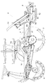
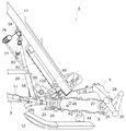
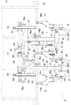
図1及び図2に示すように、右及び左の前輪1、右及び左の後輪2により支持された機体の後部に、リンク機構3及びリンク機構3を昇降駆動する油圧シリンダ4が備えられており、リンク機構3に3条植型式の苗植付装置5が支持されて、3条植型式の乗用型田植機が構成されている。
[1]
As shown in FIGS. 1 and 2, a
図1,2,4に示すように、苗植付装置5は、伝動ケース6及び支持フレーム7、回転駆動される3つの植付アーム8,9,10(植付機構に相当)、苗のせ台11及び一つの横長のフロート12等を備えて構成されている。機体に備えられた運転席13の下側にエンジン14及びミッションケース15が備えられ、エンジン14の動力が伝動ベルト16を介してミッションケース15に伝達され変速されて右及び左の前輪1、右及び左の後輪2に伝達されており、エンジン14の動力がミッションケース15からPTO軸17を介して苗植付装置5に伝達されている。
As shown in FIGS. 1, 2, and 4, the
[2]
次に、伝動ケース6及び支持フレーム7、植付アーム8,9,10の回転駆動構造について説明する。
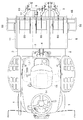
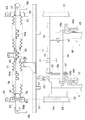
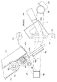
図3及び図4に示すように、角パイプで構成された支持フレーム18が苗植付装置5の左右方向に配置され、支持フレーム18に支持軸19が溶接によって前向きに固定されている。支持リンク20がリンク機構3の後部に取り付けられ、支持リンク20の下部にボス部21が固定されており、支持軸19がボス部材21に回転自在に支持されて、苗植付装置5がボス部材7の前後方向のローリング軸芯P1周りにローリング自在に支持されている。平面視において苗植付装置5の支持軸(ローリング軸芯P1)が苗植付装置5の左右中央に位置しており(図4参照)、苗植付装置5の支持軸(ローリング軸芯P1)が機体の左右中央が一致している(図2参照)。
[2]
Next, the rotational drive structure of the
As shown in FIGS. 3 and 4, a
図3,4,7に示すように、支持フレーム18の左端部に基板18aが溶接により固定されており、鋳物製で左右2分割構造の伝動ケース6が、支持フレーム18の基板18aにボルト42で固定されて後方に延出されている。角パイプで構成された支持フレーム7が、支持フレーム18の右側部に溶接により固定されて後方に延出されている。伝動ケース6及び支持フレーム7の後部にブラケット44が固定されて、フロート12の後部がブラケット44の横軸芯P2周りに上下揺動自在に支持されており、フロート12の後端部が伝動ケース6及び支持フレーム7の後端部よりも前側(図3の紙面左方)に位置している。この場合、平面視において、苗植付装置5の支持軸19(ローリング軸芯P1)(苗植付装置5の左右中央)から伝動ケース6までの距離と、苗植付装置5の支持軸19(ローリング軸芯P1)(苗植付装置5の左右中央)から支持フレーム7までの距離とが略同じものとなっている(図4参照)。
As shown in FIGS. 3, 4, and 7, the
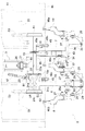
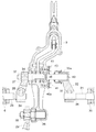
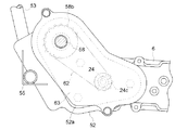
図3,4,7に示すように、伝動ケース6の前部の右側部(ローリング軸芯P1側の部分)に、入力軸22が前方に突出するように備えられて、入力軸22とPTO軸17とが自在継手23を介して接続されている。伝動ケース6の前部の内部に伝動軸24が苗植付装置5の左右方向に備えられて、伝動軸24に固定されたベベルギヤ24aが、入力軸22に固定されたベベルギヤ22aに咬合している。伝動ケース6の後部に駆動軸25が苗植付装置5の左右方向に備えられており、駆動軸25に固定されたスプロケット25aと伝動軸24に固定されたスプロケット24bとに亘って、伝動ケース6に内装された伝動チェーン26(伝動機構に相当)が巻回されている。
As shown in FIGS. 3, 4, and 7, the
図3及び図4に示すように、駆動軸25が伝動ケース6の後部から右及び左横側方に突出しており、駆動軸25の右及び左端部に駆動アーム27が固定され、駆動アーム27に植付アーム8,9が回転自在に支持されている。板材をコ字状に折り曲げて構成された支持部材28が伝動ケース6の後部に固定され、支持部材28の後部に右及び左のアーム29が前後に揺動自在に支持されており、伝動ケース6の右及び左の植付アーム8,9に、右及び左のアーム29が回転自在に接続されている。これにより、伝動ケース6の右の植付アーム9が、苗植付装置5の支持軸19(ローリング軸芯P1)(苗植付装置5の左右中央)の位置に位置している(図4参照)。
As shown in FIGS. 3 and 4, the
図4に示すように、丸パイプで構成された支持フレーム30が、支持フレーム7の後端部に苗植付装置5の左右方向に固定されている。駆動軸31が支持フレーム30に回転自在に支持されて伝動ケース6の右の植付アーム9に向けて延出されており、駆動軸31の左端部にクランクアーム32が取り付けられて、クランクアーム32が伝動ケース6の右の植付アーム9に接続されている。駆動軸31の右端部に駆動アーム27が固定され、駆動アーム27に植付アーム10が回転自在に支持されている。板材をL字状に折り曲げて構成された支持部材33が支持フレーム30の後部に固定され、支持部材33の後部にアーム29が前後に揺動自在に支持されており、支持フレーム7の植付アーム10にアーム29が回転自在に接続されている。
As shown in FIG. 4, a
以上の構造により図4及び図7に示すように、PTO軸17の動力が入力軸22、伝動軸24及び伝動チェーン26を介して駆動軸25に伝達されて、伝動ケース6の右及び左の植付アーム8,9が回転駆動されるのであり、伝動ケース6の右の植付アーム9を介して駆動軸31に動力が伝達されて、支持フレーム7の植付アーム10が回転駆動される。これにより、伝動ケース6の右及び左の植付アーム8,9、支持フレーム7の植付アーム10が一体で回転駆動されて、苗のせ台11の下部(後述する支持レール46の苗取り出し口46a)から苗を取り出して田面に植え付ける。
4 and 7, the power of the
[3]
次に、伝動ケース6の右の植付アーム9の付近の構造について説明する。
図4及び図8に示すように、駆動アーム27がキー34を介して駆動軸25の右端部に取り付けられており、抜け止め用のボルト35が駆動アーム27に取り付けられている。伝動ケース6の右の植付アーム9の内部にカム軸36(植付アーム9の苗押し出し具(図示せず)を進退駆動するもの)が回転自在に支持されて、伝動ケース6の右の植付アーム9からカム軸36が左側に突出しており、駆動アーム27とカム軸36とがキー34を介して取り付けられて、抜け止め用のナット37がカム軸36に取り付けられている。伝動ケース6の右の植付アーム9に支点軸38が回転自在に支持され、支点軸38が右のアーム29に挿入されて、抜け止め用のナット39が支点軸38に取り付けられている。
[3]
Next, the structure in the vicinity of the
As shown in FIGS. 4 and 8, the
図4及び図8に示すように、伝動ケース6の右の植付アーム9と支持フレーム7の植付アーム10とは同じもので、伝動ケース6の右の植付アーム9(支持フレーム7の植付アーム10)の右側部に穴部が形成されており、伝動ケース6の右の植付アーム9の穴部に雌ネジが形成されいる。側面視で三角形状の基板40aを備えた支点軸40が用意されており、伝動ケース6の右の植付アーム9の穴部に、支点軸40の基板40aがボルト41により固定されている。
As shown in FIGS. 4 and 8, the
図4及び図8に示すように、クランクアーム32がキー34を介して駆動軸31の左端部に連結されて、抜け止め用のボルト35がクランクアーム27に取り付けられており、クランクアーム32と支持フレーム30との間隔が少し大きなものに設定されている。クランクアーム32の端部にボス部32aが形成されて、支点軸40がクランクアーム32のボス部32aに相対回転自在に挿入されており(嵌合及び離脱可能な状態)、ゴム製のシールカバー43が支点軸40とクランクアーム32のボス部32aとに亘って取り付けられている。これにより、クランクアーム32が伝動ケース6の右の植付アーム9に接続された状態となっている。
As shown in FIGS. 4 and 8, the
以上の構造により、伝動ケース6の右の植付アーム9を取り外す場合、図4及び図8に示すように、クランクアーム32からボルト35を取り外し、クランクアーム32を駆動軸31に沿ってキー34から外れるまで支持フレーム30側(図8の紙面右方)に移動させて、クランクアーム32のボス部32aを支点軸40から抜き出す。この後、伝動ケース6の右の植付アーム9の位相から外れるように、クランクアーム32を駆動軸31周りに回転させる(180度程度)。
With the above structure, when the
次に図4及び図8に示すように、ナット37,39を取り外し、カム軸36及び支点軸38を駆動アーム27及び右のアーム29から図8の紙面右方に抜き出して、伝動ケース6の右の植付アーム9を取り外す。又は駆動アーム27からボルト35を取り外して、駆動アーム27を駆動軸25から図8の紙面右方に抜き出し、ナット39を取り外して、支点軸38を右のアーム29から図8の紙面右方に抜き出して、伝動ケース6の右の植付アーム9を取り外す。
Next, as shown in FIGS. 4 and 8, the nuts 37 and 39 are removed, and the
以上の構造において、図4及び図8に示す駆動アーム27、キー34、駆動軸25,31、ボルト35、カム軸36、ナット37、支点軸38、ナット39等の構造は、伝動ケース6の左の植付アーム8及び支持フレーム7の植付アーム10にも、同様に備えられている。これにより、前述と同様な操作を行うことにより(伝動ケース6の左の植付アーム8及び支持フレーム7の植付アーム10に対して、クランクアーム32は備えられていないので、クランクアーム32に関する操作は不要)、伝動ケース6の左の植付アーム8及び支持フレーム7の植付アーム10を取り外すことができる。
In the above structure, the structure of the
[4]
次に、苗のせ台11の支持構造について説明する。
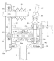
図2及び図3に示すように、苗のせ台11の下部を横移動自在に支持する支持レール46が備えられ、図4,6,10に示すように、支持レール46の下部の2箇所に支持ロッド46bが下向きに固定されており、伝動ケース6及び支持フレーム7に固定されたブラケット45に、支持レール46の支持ロッド46bが挿入されている。支持フレーム18に固定されたブラケット47及び伝動ケース6の前部に亘って、操作軸48が回転自在に支持されて、操作軸48に固定されたアーム48aが支持レール46の支持ロッド46bの付近を支持している。
[4]
Next, the support structure of the
As shown in FIGS. 2 and 3, support rails 46 are provided to support the lower part of the
図4,6,10に示すように、操作軸48に固定された操作レバー49が、支持フレーム7の左側部(支持フレーム7の植付アーム10とは反対側)に沿って後方に延出されており、支持フレーム7にレバーガイド50が固定されて、レバーガイド50の縦長の案内孔に操作レバー49が挿入されている。操作レバー49の後部下部に板片状の折り曲げ部49aが備えられており、操作レバー49の折り曲げ部49aをレバーガイド50の案内孔の係止部に係合させることにより、操作レバー49を所望の位置に保持することができる。
As shown in FIGS. 4, 6, and 10, the
これにより、図4及び図10に示すように、操作レバー49及びレバーガイド50が、伝動ケース6の右の植付アーム9と支持フレーム7の植付アーム10との間に位置している。この場合に、レバーガイド50の案内孔の左側部にガイド部50aが存在しているので、操作レバー49が図4の紙面左方にたわもうとしても、操作レバー49がレバーガイド50のガイド部50aに止められるので、操作レバー49に伝動ケース6の右の植付アーム9が接触するようなことがない。
Accordingly, as shown in FIGS. 4 and 10, the
図4,5,6に示すように、板金製で箱状の支持フレーム51が支持フレーム18の右端部に溶接により固定されて、板金製で箱状の支持フレーム52が支持フレーム18の左端部にボルトにより固定されており、支持フレーム51,52に溶接により固定された支持フレーム53が上方に延出されている。図3及び図11に示すように、苗植付装置5の左右方向に沿って支持レール54が苗のせ台11の上部に固定されており、支持レール54が支持フレーム53の上部に横移動自在且つ上下動自在に支持されている。
As shown in FIGS. 4, 5, and 6, a box-shaped
図1,2,4に示すように、丸パイプ状の支持フレーム55が支持フレーム18,52に溶接により固定されて右及び左側方に延出されており、L字状に折り曲げられた保護フレーム56が支持フレーム55に取り付けられている。保護フレーム56が支持レール46の右及び左端部の外側に位置しており、保護フレーム56により支持レール46の右及び左端部が保護されている。
As shown in FIGS. 1, 2, and 4, a round pipe-
以上の構造により、図6及び図10に示すように、操作レバー49をレバーガイド50の案内孔に沿って上下に操作することにより、操作軸48のアーム48aが上下に操作されて、支持レール46及び苗のせ台11の位置を上下に変更することができるのであり、操作レバー49の折り曲げ部49aをレバーガイド50の案内孔の係止部に係合させて、操作レバー49を所望の位置に保持することにより、支持レール46及び苗のせ台11の位置を固定することができる。伝動ケース6の右及び左の植付アーム8,9、支持フレーム7の植付アーム10の回転駆動軌跡は一定であるので、前述のように支持レール46及び苗のせ台11の位置の上下に変更することにより、伝動ケース6の右及び左の植付アーム8,9、支持フレーム7の植付アーム10が、苗のせ台11の下部(支持レール46の苗取り出し口46a)から取り出す苗の量を変更することができる。
With the above structure, as shown in FIGS. 6 and 10, by operating the
[5]
次に、苗のせ台11の往復横送り駆動の構造について説明する。
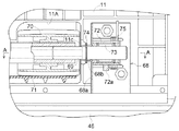
図3,5,6に示すように、支持フレーム51,52に合成樹脂製のブッシュ57が取り付けられ、ブッシュ57に横送り軸58の右及び左側部が回転自在に支持されて、円筒状の送り部材59が横送り軸58に回転自在に外嵌されており、送り部材59に支持された送り部材60の先端が、横送り軸58の螺旋溝58aに挿入されている。苗のせ台11と送り部材59とが接続されており、伸縮自在なゴム製のカバー61が送り部材59とブッシュ57とに亘って接続されて、カバー61により横送り軸58が覆われている。
[5]
Next, the structure of the reciprocating lateral feed drive of the
As shown in FIGS. 3, 5, and 6, a
図5,6,7,9に示すように、伝動軸24の左端部にスプロケット24cが固定されて支持フレーム52の内部に入り込んでおり、支持フレーム52の内部においてスプロケット58bが横送り軸58に固定され、伝動軸24のスプロケット24cと横送り軸58のスプロケット58bとに亘って、伝動チェーン62(伝動機構に相当)が巻回されている。これにより、伝動軸24のスプロケット24c、横送り軸58のスプロケット58b及び伝動チェーン62が支持フレーム52の内部に配置されることになり、支持フレーム52を塞ぐ平板状のカバー63が取り付けられている。
As shown in FIGS. 5, 6, 7, and 9, a
図7及び図9に示すように、支持フレーム52及びカバー63の下部の部分に開口部52aが形成されるように、支持フレーム52及びカバー63の形状が設定されており、支持フレーム52及びカバー63の内部に入った水が、支持フレーム52の開口部52aから出て行くようになっている。この場合、支持フレーム52とカバー63との間、伝動軸24と支持フレーム52及びカバー63との間等に、特にシール部材等は設けられておらず、伝動ケース6と伝動軸24との間にシール部材64が備えられている。
As shown in FIGS. 7 and 9, the shapes of the
これにより、図5,6,7に示すように、入力軸22の動力が伝動軸24及び伝動チェーン62を介して横送り軸58に伝達されて、横送り軸58が回転駆動されるのであり、横送り軸58の螺旋溝58aに沿って送り部材59,60が、所定のストロークで往復横送り駆動されて、苗のせ台11が所定のストロークで往復横送り駆動される。
As a result, as shown in FIGS. 5, 6, and 7, the power of the
[6]
次に、苗のせ台11に備えられた縦送り機構65の構造について説明する。
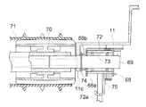
図1,2,11に示すように、苗のせ台11の3つの苗のせ面の各々に、縦送り機構65が備えられている。苗のせ台11の略全幅に亘る支持軸66が苗のせ台11の中間部に支持され、支持軸66に回転自在に支持された従動ローラー67が、苗のせ台11に形成された開口11bに配置されている。
[6]
Next, the structure of the
As shown in FIGS. 1, 2, and 11, a
図11,12,13に示すように、ブラケット68が苗のせ台11の裏側下部の右及び左端部にボルトにより固定されている。ブラケット68は金属板によって構成されて、折り曲げられて形成された支持部68a、支持部68aに形成されたボス部68b等を備えて構成されている。苗のせ台11の略全幅に亘る断面六角状の駆動軸69がブラケット68のボス部68bに回転自在に支持されて、駆動軸69に駆動ローラー70が固定され、駆動ローラー70が苗のせ台11の開口11aに配置されており、表面に多数の突起を備えた縦送りベルト71が駆動及び従動ローラー70,67に亘って巻回されている。図12及び図13に示すように、苗のせ台11の裏側における開口11aの縁部分に凸部11cが一体的に形成され、駆動軸69の右及び左側部にリング部材74が取り付けられており、リング部材74とブラケット68のボス部68b及び苗のせ台11の凸部11cにより、苗植付装置5の左右方向での駆動軸69の位置が決められている。
As shown in FIGS. 11, 12, and 13, the
図11,12,13に示すように、駆動軸69の右及び左端部にボス部72が外嵌されて、駆動軸69とボス部72との間にワンウェイクラッチ73が備えられており、ボス部72に入力アーム72aが固定されており、ボス部72の入力アーム72aが所定位置に戻るように付勢するバネ75が備えられている。図5及び図6に示すように、横送り軸58の右及び左端部に、縦送りアーム58cが固定されている。
As shown in FIGS. 11, 12, and 13, a
以上の構造により図5及び図11に示すように、横送り軸33の右及び左の縦送りアーム58cの右及び左外方に、右及び左のボス部72の入力アーム72aが位置しており、横送り軸58の右及び左の縦送りアーム58cは横送り軸58と一緒に回転駆動されている。これにより、前項[5]に記載のように、苗のせ台11が右に横送り駆動されると、右のボス部72の入力アーム72aが、横送り軸58の右の縦送りアーム58cから右外方に離れていくのであり、左のボス部72の入力アーム72aが、横送り軸58の左の縦送りアーム58cの左の横外方から横送り軸58の左の縦送りアーム58aに接近していく。
5 and 11, the
従って、図5及び図11に示すように、苗のせ台11が往復横送り駆動の右のストロークエンドに達すると、左のボス部72の入力アーム72aが横送り軸58の左の縦送りアーム58cの位置に達して、横送り軸58の左の縦送りアーム58cにより左のボス部72の入力アーム72aが所定位置から上方に駆動されて、左のワンウェイクラッチ73により駆動軸69及び縦送りベルト71が回転駆動され、苗のせ台11に載置された苗が下方(支持レール46)に送られる。
Therefore, as shown in FIGS. 5 and 11, when the
図5及び図11に示すように、苗のせ台11が左に横送り駆動されると、左のボス部72の入力アーム72aが、横送り軸58の左の縦送りアーム58cから左外方に離れていくのであり、右のボス部72の入力アーム72aが、横送り軸58の右の縦送りアーム58cの右外方から横送り軸58の右の縦送りアーム58cに接近していく。これにより、苗のせ台11が往復横送り駆動の左のストロークエンドに達すると、右のボス部72の入力アーム72aが横送り軸58の右の縦送りアーム58cの位置に達して、横送り軸58の右の縦送りアーム58cにより右のボス部72の入力アーム72aが所定位置から上方に駆動されて、右のワンウェイクラッチ73により駆動軸69及び縦送りベルト71が回転駆動され、苗のせ台11に載置された苗が下方(支持レール46)に送られる。
As shown in FIGS. 5 and 11, when the seedling table 11 is laterally driven to the left, the
[7]
図3及び図11に示すように、支持リンク20の上部と支持レール54の右及び左側部とに亘って、右及び左のバネ76が接続されており、支持リンク20の上部と右及び左の支持フレーム53とに亘って、右及び左のバネ77が接続されている。これにより、右及び左のバネ76,77によって、苗植付装置5がローリング軸芯P1周りに機体と平行な姿勢に付勢されている。
[7]
As shown in FIGS. 3 and 11, right and left
図4及び図7に示すように、入力軸22が回転方向(矢印B1)(苗植付装置5の正面視において、入力軸22の回転方向が左周り)に回転駆動されており、伝動軸24及び駆動軸25,31が回転方向(矢印B2,B3)に回転駆動されている。これによって、入力軸22の回転動力により、苗植付装置5がローリング軸芯P1周りに入力軸22の回転方向(矢印B1)に傾斜しようとする。
As shown in FIGS. 4 and 7, the
これに対して図4に示すように、苗植付装置5の正面視において、苗植付装置5の支持軸19(ローリング軸芯P1)から右側に伝動ケース6が位置し、苗植付装置5の支持軸19(ローリング軸芯P1)から左側に支持フレーム7が位置している。この場合、伝動ケース6の右及び左の植付アーム8,9によって支持フレーム7の植付アーム10が回転駆動されており、伝動ケース6に備えられた伝動軸24及び伝動チェーン26等が支持フレーム7に備えられていないので、伝動ケース6が支持フレーム7に比べて重いものとなり、支持フレーム7が伝動ケース6に比べて軽いものとなっている。
On the other hand, as shown in FIG. 4, in the front view of the
これにより、図4に示すように、苗植付装置5の重心が苗植付装置5の支持軸19(ローリング軸芯P1)から右側(伝動ケース6側)に位置することになり、苗植付装置5の重心により入力軸22の回転方向(矢印B1)とは逆方向に苗植付装置5を傾斜させようとするモーメントが発生することになって、入力軸22の回転動力により苗植付装置5がローリング軸芯P1周りに入力軸22の回転方向(矢印B1)に傾斜しようとする状態が抑えられる。
As a result, as shown in FIG. 4, the center of gravity of the
この場合、図4及び図7に示すように、苗植付装置5の正面視において、入力軸22が伝動ケース6の前部に備えられて、苗植付装置5の支持軸19(ローリング軸芯P1)から右側に入力軸22が位置している点、並びに、入力軸22の動力を横送り軸58に伝達する伝動チェーン62が、苗植付装置5の支持軸19(ローリング軸芯P1)から右側に位置している点により、苗植付装置5の重心が苗植付装置5の支持軸19(ローリング軸芯P1)から右側(伝動ケース6側)に位置する状態が助長される。
In this case, as shown in FIGS. 4 and 7, the
[発明の実施の第1別形態]
前述の[発明を実施するための最良の形態]において、次のように構成してもよい。
入力軸22の回転方向を苗植付装置5の正面視において、右周り(図4及び図7の矢印B1の逆方向)に設定し、苗植付装置5の正面視において、苗植付装置5の支持軸19(ローリング軸芯P1)から左側に伝動ケース6を配置し、苗植付装置5の支持軸19(ローリング軸芯P1)から右側に支持フレーム7を配置する。苗植付装置5の正面視において、入力軸22を伝動ケース6の前部に備えて、苗植付装置5の支持軸19(ローリング軸芯P1)から左側に入力軸22を配置し、伝動チェーン62を苗植付装置5の支持軸19(ローリング軸芯P1)から左側に配置する。
[First Alternative Embodiment of the Invention]
In the above-mentioned [Best Mode for Carrying Out the Invention], the following configuration may be adopted.
The rotation direction of the
[発明の実施の第2別形態]
前述の[発明を実施するための最良の形態][発明の実施の第1別形態]において、田面に対する苗植付装置5の左右方向の角度を検出する角度センサー(図示せず)を備え、支持リンク20の上部と苗植付装置5とに亘って、アクチュエータ(図示せず)を接続するように構成してもよい。これにより、角度センサーの検出値に基づいて、苗植付装置5が田面と平行(又は所望の姿勢)となるように、アクチュエータにより苗植付装置5をローリング軸芯P1周りに駆動するように構成する。
[Second Embodiment of the Invention]
In the above-mentioned [Best Mode for Carrying Out the Invention] [First Alternative Embodiment], an angle sensor (not shown) for detecting the angle of the
[発明の実施の第3別形態]
前述の[発明を実施するための最良の形態][発明の実施の第1別形態][発明の実施の第2別形態]において、クランクアーム32のボス部32aに相当する構造を伝動ケース6の右の植付アーム9に備え、支点軸40に相当する構造をクランクアーム32に備えるように構成してもよい。又、クランクアーム32を駆動軸31から取り外すように構成したり、クランクアーム32を駆動軸31から取り外し且つ支点軸40を伝動ケース6の右の植付アーム9から取り外すように構成してもよい。
[Third Another Embodiment of the Invention]
In the above-mentioned [Best Mode for Carrying Out the Invention] [First Alternative Embodiment of the Invention] [Second Alternative Embodiment of the Invention], the structure corresponding to the
[発明の実施の第4別形態]
前述の[発明を実施するための最良の形態][発明の実施の第1別形態]〜[発明の実施の第3別形態]において、植付アーム8,9,10に代えて、回転駆動される回転ケースの両端に一対の植付アームを備えたロータリ型式の植付機構を、伝動ケース6及び支持フレーム7に備えるように構成してもよい。伝動チェーン26,62に代えて、伝動軸(図示せず)や伝動ギヤを使用してもよい。
[Fourth Embodiment of the Invention]
In the above-mentioned [Best Mode for Carrying Out the Invention] [First Alternative Embodiment of the Invention] to [Third Alternative Embodiment of the Invention], instead of the planting
5 苗植付装置
6 伝動ケース
7 支持フレーム
8,9,10 植付機構
11 苗のせ台
17 PTO軸
22 入力軸
26,62 伝動機構
31 駆動軸
58 横送り軸
P1 ローリング軸芯
5
Claims (4)
前記苗植付装置の正面視において、前記入力軸の回転方向を右周りに設定し苗植付装置の重心をローリング軸芯に対して左側に位置させ、又は、前記入力軸の回転方向を左周りに設定し苗植付装置の重心をローリング軸芯に対して右側に位置させてある乗用型田植機。 A seedling planting device is supported in a rolling manner around a rolling axis center in the front-rear direction of the rear part of the machine body, and a PTO shaft from the machine body is connected to an input shaft projecting forward from the seedling planting apparatus. Is transmitted to the seedling planting device via the PTO shaft and the input shaft,
In the front view of the seedling planting device, the rotation direction of the input shaft is set clockwise and the center of gravity of the seedling planting device is positioned on the left side with respect to the rolling axis, or the rotation direction of the input shaft is set to the left Riding type rice transplanter that is set around and the center of gravity of the seedling planting device is located on the right side of the rolling axis.
後部に植付機構を回転自在に支持した支持フレームを前記苗植付装置に備え、前記伝動ケースの植付機構と支持フレームの植付機構とに亘って駆動軸を接続して、前記伝動ケースの植付機構と支持フレームの植付機構とが一体で回転駆動されるように構成すると共に、
前記伝動ケースをローリング軸芯に対して右又は左側に位置させ、前記支持ケースをローリング軸芯に対して伝動ケースの反対側の左又は右側に位置させることにより、前記苗植付装置の重心がローリング軸芯に対して右又は左側に位置するように構成してある請求項1に記載の乗用型田植機。 The seedling planting device includes a transmission case that rotatably supports the planting mechanism at the rear, so that the power of the input shaft is transmitted to the planting mechanism of the transmission case via the transmission mechanism built in the transmission case. To configure
The seedling planting apparatus includes a support frame that rotatably supports a planting mechanism at a rear portion, and a drive shaft is connected across the planting mechanism of the transmission case and the planting mechanism of the support frame, and the transmission case The planting mechanism and the planting mechanism of the support frame are configured to be integrally rotated and driven.
By positioning the transmission case on the right or left side with respect to the rolling shaft core and positioning the support case on the left or right side opposite to the transmission case, the center of gravity of the seedling planting device can be increased. The riding type rice transplanter according to claim 1, which is configured to be positioned on the right or left side with respect to the rolling shaft core.
前記入力軸の動力を横送り軸に伝達する伝動機構を、前記伝動ケースと横送り軸の伝動ケース側の端部とに亘って架設してある請求項2又は3に記載の乗用型田植機。 A transverse feed shaft that reciprocally drives the seedling support supported by the seedling planting device to the left and right is supported by the seedling planting device so as to be rotatable in the left and right directions,
4. The riding type rice transplanter according to claim 2, wherein a transmission mechanism for transmitting the power of the input shaft to the lateral feed shaft is constructed across the transmission case and an end portion of the lateral feed shaft on the transmission case side. .
Priority Applications (1)
| Application Number | Priority Date | Filing Date | Title |
|---|---|---|---|
| JP2005033173A JP2006217841A (en) | 2005-02-09 | 2005-02-09 | Ride type rice transplanter |
Applications Claiming Priority (1)
| Application Number | Priority Date | Filing Date | Title |
|---|---|---|---|
| JP2005033173A JP2006217841A (en) | 2005-02-09 | 2005-02-09 | Ride type rice transplanter |
Publications (1)
| Publication Number | Publication Date |
|---|---|
| JP2006217841A true JP2006217841A (en) | 2006-08-24 |
Family
ID=36980558
Family Applications (1)
| Application Number | Title | Priority Date | Filing Date |
|---|---|---|---|
| JP2005033173A Pending JP2006217841A (en) | 2005-02-09 | 2005-02-09 | Ride type rice transplanter |
Country Status (1)
| Country | Link |
|---|---|
| JP (1) | JP2006217841A (en) |
Cited By (1)
| Publication number | Priority date | Publication date | Assignee | Title |
|---|---|---|---|---|
| CN110710367A (en) * | 2019-10-28 | 2020-01-21 | 栾翠莲 | Three-dimensional reinforced wide-narrow row rice transplanter |
-
2005
- 2005-02-09 JP JP2005033173A patent/JP2006217841A/en active Pending
Cited By (1)
| Publication number | Priority date | Publication date | Assignee | Title |
|---|---|---|---|---|
| CN110710367A (en) * | 2019-10-28 | 2020-01-21 | 栾翠莲 | Three-dimensional reinforced wide-narrow row rice transplanter |
Similar Documents
| Publication | Publication Date | Title |
|---|---|---|
| JP5134283B2 (en) | Paddy field machine | |
| JP4484591B2 (en) | Ride type rice transplanter | |
| JP2005341881A5 (en) | ||
| JP4957427B2 (en) | Seedling transplanter | |
| JP3995621B2 (en) | Paddy field machine | |
| JP2006217841A (en) | Ride type rice transplanter | |
| JP4423213B2 (en) | Seedling planting equipment | |
| JP4633424B2 (en) | Rice transplanter | |
| JP4051498B2 (en) | Agricultural machine | |
| JP4371901B2 (en) | Ride type rice transplanter | |
| JP2008253231A (en) | Traveling body | |
| JP5706245B2 (en) | Rice transplanter | |
| JP4101158B2 (en) | Paddy field machine | |
| JP2007189912A (en) | Farm work vehicle | |
| JP3632418B2 (en) | Seedling transplanter | |
| JP2014103870A (en) | Seedling transplanter | |
| JP4233489B2 (en) | Three row planting type rice transplanter | |
| JP4101268B2 (en) | Seedling planting equipment for riding rice transplanters | |
| JP2006304647A (en) | Rice transplanter | |
| JP6242327B2 (en) | Rice transplanter seedling planting equipment | |
| JP4233488B2 (en) | Ride type rice transplanter | |
| JP2013202011A (en) | Seedling transplanter | |
| JP2008022860A (en) | Odd-row planting seedling transplanter | |
| JP4484755B2 (en) | Rotating body for scraping of rice transplanter | |
| JP2005143410A5 (en) |
Legal Events
| Date | Code | Title | Description |
|---|---|---|---|
| A621 | Written request for application examination |
Effective date: 20070328 Free format text: JAPANESE INTERMEDIATE CODE: A621 |
|
| A977 | Report on retrieval |
Effective date: 20080807 Free format text: JAPANESE INTERMEDIATE CODE: A971007 |
|
| A131 | Notification of reasons for refusal |
Effective date: 20080828 Free format text: JAPANESE INTERMEDIATE CODE: A131 |
|
| A02 | Decision of refusal |
Free format text: JAPANESE INTERMEDIATE CODE: A02 Effective date: 20090108 |