JP4484591B2 - Ride type rice transplanter - Google Patents
Ride type rice transplanter Download PDFInfo
- Publication number
- JP4484591B2 JP4484591B2 JP2004166055A JP2004166055A JP4484591B2 JP 4484591 B2 JP4484591 B2 JP 4484591B2 JP 2004166055 A JP2004166055 A JP 2004166055A JP 2004166055 A JP2004166055 A JP 2004166055A JP 4484591 B2 JP4484591 B2 JP 4484591B2
- Authority
- JP
- Japan
- Prior art keywords
- scraping device
- seedling planting
- planting
- scraping
- rice transplanter
- Prior art date
- Legal status (The legal status is an assumption and is not a legal conclusion. Google has not performed a legal analysis and makes no representation as to the accuracy of the status listed.)
- Expired - Fee Related
Links
Images


Landscapes
- Soil Working Implements (AREA)
- Transplanting Machines (AREA)
Description
本発明は乗用型田植機の構造に関する。 The present invention relates to a structure of a riding type rice transplanter.
[I]
(構成)
本発明の第1特徴は、乗用型田植機において次のように構成することにある。
前輪及び後輪で支持された機体の後部にリンク機構を備え、リンク機構を昇降駆動する油圧シリンダを備えて、リンク機構に苗植付装置を支持する。左右方向に配置された支持フレームに伝動ケースを連結して、伝動ケースの後部に植付機構を備え、伝動ケースの下側にフロートの後部を上下に揺動自在に支持して、苗植付装置を構成する。フロートの前部に支持された連係ロッドを、フロートの前部への支持箇所から支持フレームの後側を通して上方に延出して、連係ロッドによって田面から苗植付装置までの高さを検出するように構成する。田面から苗植付装置までの高さが設定値に維持されるように、油圧シリンダにより苗植付装置が自動的に昇降駆動されるように構成する。
[I]
(Constitution)
The first feature of the present invention resides in the following configuration in a riding type rice transplanter.
A link mechanism is provided at the rear part of the machine body supported by the front wheel and the rear wheel, and a hydraulic cylinder for moving the link mechanism up and down is provided, and the seedling planting device is supported by the link mechanism. A transmission case is connected to a support frame arranged in the left-right direction, a planting mechanism is provided at the rear part of the transmission case, and the rear part of the float is swingably supported up and down on the lower side of the transmission case to plant seedlings. Configure the device. The linkage rod which is supported on the front portion of the float, and extending upwardly through the rear side of the supporting frame from the support point to the front of the float height from paddy by linkage rods until seedling planting apparatus Is configured to detect The seedling planting device is configured to automatically move up and down by a hydraulic cylinder so that the height from the paddy surface to the seedling planting device is maintained at a set value.
[II]
(構成)
本発明の第2特徴は、本発明の第1特徴の乗用型田植機において次のように構成することにある。
田面に接地した状態で左右方向の横軸芯周りに回転することにより田面の代掻きを行う回転体を備えて構成された代掻き装置を、苗植付装置と後輪との間に備える。
[II]
(Constitution)
The second feature of the present invention resides in the following configuration in the riding rice transplanter of the first feature of the present invention.
A scraping device configured to include a rotating body that scrapes the paddy surface by rotating around the horizontal axis in the left-right direction while being in contact with the paddy surface is provided between the seedling planting device and the rear wheel.
[III]
(構成)
本発明の第3特徴は、本発明の第2特徴の乗用型田植機において次のように構成することにある。
苗植付装置に代掻き装置を支持し、苗植付装置に対する代掻き装置の高さを変更自在な高さ調節機構を備える。
[III]
(Constitution)
The third feature of the present invention resides in the following configuration in the riding type rice transplanter of the second feature of the present invention.
A seeding planting device is supported by a scraping device, and a height adjusting mechanism is provided that can change the height of the dressing device relative to the seedling planting device.
(作用) (Function)
乗用型田植機では一般に、苗植付装置が田面から設定高さに維持されるように(苗の植付深さが設定深さに維持されるように)、リンク機構により苗植付装置が自動的に昇降駆動される昇降制御機能を備えており、前述の設定高さを変更することによって苗の植付深さ(設定深さ)を変更することができる。
この場合、本発明の第3特徴のように、苗植付装置に対する代掻き装置の高さを変更自在な高さ調節機構を備えることにより、前述の設定高さを変更することによって苗の植付深さ(設定深さ)を変更しても、高さ調節機構を操作することによって、代掻き装置の田面への接地状態を一定に維持したり、代掻き装置の田面への接地状態を任意に変更したりすることができる。
In general, in a riding type rice transplanter, the seedling planting device is maintained by a link mechanism so that the seedling planting device is maintained at a set height from the rice field (so that the seedling planting depth is maintained at the set depth). A lifting control function that is automatically driven to move up and down is provided, and the seedling planting depth (set depth) can be changed by changing the above-described set height.
In this case, as in the third feature of the present invention, by providing a height adjusting mechanism capable of changing the height of the scraping device relative to the seedling planting device, planting the seedling by changing the set height described above. Even if the depth (set depth) is changed, by operating the height adjustment mechanism, the grounding state of the scraping device to the surface can be kept constant, or the grounding state of the scraping device to the surface can be changed arbitrarily. You can do it.
(発明の効果) (The invention's effect)
本発明の第3特徴によると、設定高さを変更することによって苗の植付深さ(設定深さ)を変更しても、代掻き装置の田面への接地状態を一定に維持したり、代掻き装置の田面への接地状態を任意に変更したりすることができるようになって、代掻き装置の代掻き(整地)性能を向上させることができた。 According to the third feature of the present invention, even if the planting depth (set depth) of the seedling is changed by changing the set height, the ground contact state of the padding device on the paddy surface is kept constant, It has become possible to arbitrarily change the ground contact state of the device to the surface, and the scraping (leveling) performance of the scraping device could be improved.
[IV]
(構成)
本発明の第4特徴は、本発明の第2又は第3特徴の乗用型田植機において次のように構成することにある。
複数の回転体を備えて代掻き装置を構成し、田面の泥を後方に逃がすリング状の隙間部を代掻き装置の回転体の間に備える。
[IV]
(Constitution)
A fourth feature of the present invention resides in the following configuration in the riding type rice transplanter of the second or third feature of the present invention.
A scraping device is configured by including a plurality of rotating bodies, and a ring-shaped gap is provided between the rotating bodies of the scraping device to allow the mud on the surface to escape backward.
(作用)
苗植付装置の前方の田面を代掻き(整地)する為に、代掻き装置は一般に苗植付装置の横幅に亘るような横幅の大きなものになることが多いので、機体の進行に伴って代掻き装置の回転体が田面の泥を前方に押してしまうことが考えられる。
(Function)
In order to scratch the surface in front of the seedling planting device (leveling), the scraping device generally has a large width across the width of the seedling planting device. It can be considered that the rotating body of this would push the mud on the surface forward.
本発明の第4特徴によると、複数の回転体を備えて代掻き装置を構成し、田面の泥を後方に逃がすリング状の隙間部を代掻き装置の回転体の間に備えており、機体の進行に伴って田面の泥が代掻き装置の隙間部を通って後方に逃げるので、機体の進行に伴って代掻き装置の回転体が田面の泥を前方に押してしまう状態を少なくすることができる。 According to the fourth aspect of the present invention, the scraper is configured by including a plurality of rotating bodies, and a ring-shaped gap for allowing the mud on the surface to escape backward is provided between the rotating bodies of the scraper, Accordingly, the mud on the paddy surface escapes backward through the gap of the scraping device, so that the state in which the rotating body of the scraping device pushes the mud on the paddy surface forward with the progress of the machine body can be reduced.
(発明の効果)
本発明の第4特徴によると、機体の進行に伴って代掻き装置の回転体が田面の泥を前方に押してしまう状態を少なくすることができて、代掻き装置の代掻き(整地)性能を向上させることができた。
(The invention's effect)
According to the fourth feature of the present invention, it is possible to reduce the state in which the rotating body of the scraping device pushes the mud on the paddy field forward as the aircraft advances, and improve the scraping (leveling) performance of the scraping device. I was able to.
[V]
(構成)
本発明の第5特徴は、本発明の第4特徴の乗用型田植機において次のように構成することにある。
後輪の後方に代掻き装置の隙間部を位置させる。
[V]
(Constitution)
The fifth feature of the present invention resides in the following configuration in the riding type rice transplanter of the fourth feature of the present invention.
The gap portion of the scraping device is positioned behind the rear wheel.
(作用)
乗用型田植機が水田を走行する際、後輪が田面に入り込むと、後輪により田面に溝が掘られようとするのに加えて、溝の両側に小さな泥の山が土手のように盛り上げられるような状態になることがある。
(Function)
When riding a rice transplanter traveling on a paddy field, if the rear wheel enters the paddy field, the rear wheel tries to dig a groove on the paddy surface, and a small mud pile rises like a bank on both sides of the groove. May be in a state where
複数の回転体を備えて代掻き装置を構成した場合、本発明の第5特徴のように、後輪の後方に代掻き装置の隙間部を位置させると、代掻き装置の回転体の端部が前述の田面の溝の両側の盛り上がり部分に位置することになるので、代掻き装置の回転体の端部により田面の溝の両側の盛り上がり部分が崩されて、崩された泥が代掻き装置の回転体に邪魔されることなく(代掻き装置の隙間部に位置しており、代掻き装置の回転体が存在していない点による)、田面の溝に送り込まれるようになることが期待できる。 When the scraping device is configured with a plurality of rotating bodies, as in the fifth feature of the present invention, when the gap portion of the scraping device is positioned behind the rear wheel, the end of the rotating body of the scraping device is Since it is located on the raised parts on both sides of the groove on the surface, the raised parts on both sides of the groove on the surface are broken by the end of the rotating body of the scraping device, and the broken mud disturbs the rotating body of the scraping device. It can be expected that it will be fed into the groove on the paddy surface (because it is located in the gap of the scraping device and the rotating body of the scraping device is not present).
(発明の効果)
本発明の第5特徴によると、後輪により田面に溝が掘られようとするのに加えて、溝の両側に小さな泥の山が土手のように盛り上げられるような状態になっても、田面の溝の両側の盛り上がり部分が崩されて、崩された泥が田面の溝に送り込まれ、田面の溝が適切に埋められるようにすることができて、代掻き装置の代掻き(整地)性能を向上させることができた。
(The invention's effect)
According to the fifth aspect of the present invention, in addition to the fact that the rear wheel tries to dig a groove on the surface, a small mud pile on both sides of the groove is raised like a bank. The raised parts on both sides of the groove of the paddy are collapsed, and the broken mud is sent into the groove on the paddy surface so that the paddle groove can be filled properly, improving the scraping (leveling) performance of the scraping device I was able to.
[VI]
(構成)
本発明の第6特徴は、本発明の第4又は第5特徴の乗用型田植機において次のように構成することにある。
フロートの前方に代掻き装置の隙間部を位置させ、苗植付装置の植付機構による植付位置の前方に代掻き装置の回転体を位置させる。
[VI]
(Constitution)
The sixth feature of the present invention resides in the following configuration in the riding type rice transplanter of the fourth or fifth feature of the present invention.
The gap portion of the cutting device is positioned in front of the float , and the rotating body of the cutting device is positioned in front of the planting position by the planting mechanism of the seedling planting device.
(作用)
本発明の第6特徴によると、苗植付装置のフロートの前方に代掻き装置の隙間部が位置しているので、前項[IV]に記載のように、機体の進行に伴って田面の泥が代掻き装置の隙間部を通って後方に逃げた場合、この後方に逃げた泥が苗植付装置のフロートによって押圧される。本発明の第6特徴によると、苗植付装置の植付機構による植付位置の前方に代掻き装置の回転体が位置しているので、苗植付装置の植付機構による植付位置が適切に代掻き(整地)される。
(Function)
According to the sixth feature of the present invention, since the gap portion of the scraping device is located in front of the float of the seedling planting device, as described in the previous item [IV], mud on the surface of the paddy surface is moved along with the progress of the aircraft. When it escapes back through the clearance gap of a scraping apparatus, the mud which escaped back is pressed by the float of a seedling planting apparatus. According to the sixth feature of the present invention, since the rotating body of the scraping device is located in front of the planting position by the planting mechanism of the seedling planting device, the planting position by the planting mechanism of the seedling planting device is appropriate. It is scratched (leveling).
(発明の効果)
本発明の第6特徴によると、機体の進行に伴って代掻き装置の隙間部を通って後方に逃げた泥が苗植付装置のフロートによって押圧される点、苗植付装置の植付機構による植付位置が適切に代掻き(整地)される点によって、苗植付装置による苗の植付性能を向上させることができた。
(The invention's effect)
According to the sixth feature of the present invention, the mud that escapes backward through the gap portion of the scraping device as the aircraft progresses is pressed by the float of the seedling planting device, due to the planting mechanism of the seedling planting device The planting performance of the seedling planting device was improved by the fact that the planting position was appropriately scraped (leveled).
[VII]
(構成)
本発明の第7特徴は、本発明の第2〜第6特徴の乗用型田植機のうちのいずれか一つにおいて次のように構成することにある。
代掻き装置における右及び左の端部の回転体の外径を、代掻き装置における左右中央側の回転体の外径よりも小さなものに設定する。
[VII]
(Constitution)
The seventh feature of the present invention resides in the following configuration in any one of the riding rice transplanters of the second to sixth features of the present invention.
The outer diameter of the rotating body at the right and left ends of the scraping device is set to be smaller than the outer diameter of the rotating body on the left and right center side of the scraping device.
本発明の第8特徴は、本発明の第2〜第7特徴の乗用型田植機のうちのいずれか一つにおいて次のように構成することにある。
代掻き装置における右及び左の端部の回転体に備えられた整地体の数を、代掻き装置における左右中央側の回転体に備えられた整地体の数よりも少ないものに設定する。
The eighth feature of the present invention resides in the following configuration in any one of the riding rice transplanters of the second to seventh features of the present invention.
The number of leveling bodies provided in the rotating bodies at the right and left ends of the scraping device is set to be smaller than the number of leveling bodies provided in the right and left central rotating bodies in the scratching device.
(作用)
前項[IV]に記載のように、代掻き装置は一般に苗植付装置の横幅に亘るような横幅の大きなものになることが多いので、前回の植付行程で植え付けられた苗の近くに、代掻き装置の端部が位置することになる。これにより、機体の進行に伴って代掻き装置の端部から横外側に泥の流れが発生すると、この泥の流れによって前回の植付行程で植え付けられた苗が傾くおそれがある。
(Function)
As described in the previous section [IV], since the cutting device generally has a large width that spans the width of the seedling planting device, the cutting device is placed near the seedling planted in the previous planting process. The end of the device will be located. As a result, if a mud flow is generated laterally outward from the end portion of the scraping device as the aircraft progresses, the seedling planted in the previous planting process may be tilted by the mud flow.
本発明の第7特徴(第8特徴)によると、代掻き装置における右及び左の端部の回転体の外径が小さいので(代掻き装置における右及び左の端部の回転体に備えられた整地体の数が少ないので)、代掻き装置における右及び左の端部の回転体の田面への抵抗が小さくなり、機体の進行に伴って代掻き装置の端部から横外側に泥の流れが発生する状態が抑えられる。 According to the seventh feature (eighth feature) of the present invention, since the outer diameter of the rotating body at the right and left ends of the scraping device is small (the leveling provided to the rotating body at the right and left ends of the scraping device) Because the number of bodies is small), the resistance to the surface of the rotating body at the right and left ends of the scraping device is reduced, and mud flows from the end of the scraping device to the lateral outside as the aircraft progresses. The state is suppressed.
(発明の効果)
本発明の第7特徴(第8特徴)によると、機体の進行に伴って代掻き装置の端部から横外側に泥の流れが発生する状態を抑えることができ、この泥の流れによって前回の植付行程で植え付けられた苗が傾くような状態を少なくすることができて、苗植付装置による苗の植付性能を向上させることができた。
(The invention's effect)
According to the seventh feature (eighth feature) of the present invention, it is possible to suppress a state in which mud flows from the end of the scraping device to the lateral outer side as the aircraft progresses, and this mud flow causes the previous planting. It was possible to reduce the state in which the seedlings planted in the attachment process were tilted, and to improve the seedling planting performance by the seedling planting device.
[VIII]
(構成)
本発明の第9特徴は、本発明の第2〜第8特徴の乗用型田植機のうちのいずれか一つにおいて次のように構成することにある。
代掻き装置の回転体から後方への泥を飛散を防止するカバーを備える。
[VIII]
(Constitution)
A ninth feature of the present invention resides in the following configuration in any one of the riding rice transplanters of the second to eighth features of the present invention.
A cover is provided for preventing mud from scattering from the rotating body of the scraper.
(作用)
代掻き装置の回転体は比較的高速で回転駆動されるので、代掻き装置の回転体から田面の泥が飛散するのであり、代掻き装置の回転体から後方の苗植付装置への泥の飛散が、カバーによって防止される。
(Function)
Since the rotating body of the scraping device is driven to rotate at a relatively high speed, mud on the paddy surface scatters from the rotating body of the scraping device, and the scattering of mud from the rotating body of the scraping device to the rear seedling planting device, Prevented by the cover.
(発明の効果)
本発明の第9特徴によると、代掻き装置の回転体から後方の苗植付装置への泥の飛散を防止することができ、苗植付装置のフロートに泥が乗ることによりフロートの動作が鈍くなるような状態を防止することができて、苗植付装置による苗の植付性能を向上させることができた。
(The invention's effect)
According to the ninth feature of the present invention, it is possible to prevent mud from scattering from the rotating body of the scraping device to the rear seedling planting device, and when the mud gets on the float of the seedling planting device, the operation of the float becomes dull. It was possible to prevent such a situation, and to improve the seedling planting performance by the seedling planting apparatus.
[1]
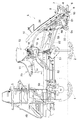
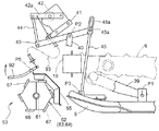
図1に示すように、右及び左の前輪1、右及び左の後輪2で支持された機体の後部に、リンク機構3及びリンク機構3を昇降駆動する油圧シリンダ4が備えられ、リンク機構3に6条植型式の苗植付装置5が支持されて、乗用型田植機が構成されている。
[1]
As shown in FIG. 1, a
図1に示すように、機体の前部にエンジン49及びミッションケース50が備えられ、ミッションケース50から右及び左横方に前車軸ケース(図示せず)が延出されて、右及び左の前車軸ケースの端部に右及び左の前輪1が左右に操向自在に支持されている。機体の後部に後車軸ケース51が支持されて、後車軸ケース51に右及び左の後輪2が支持されている。エンジン49の動力がミッションケース50、ミッションケース50に内装された前輪デフ機構(図示せず)、右及び左の前車軸ケースを介して右及び左の前輪1に伝達されており、エンジン49の動力がミッションケース50から、伝動軸52及び後車軸ケース51(後輪デフ機構は備えられていない)を介して右及び左の後輪2に伝達されている。
As shown in FIG. 1, an
図1に示すように、伝動軸52の動力を右の後輪2に伝動及び遮断自在な右のサイドクラッチ(図示せず)が後車軸ケース51に備えられており、伝動軸52の動力を左の後輪2に伝動及び遮断自在な左のサイドクラッチ(図示せず)が後車軸ケース51に備えられている。これにより、右及び左の前輪1が直進位置、直進位置と右及び左の設定角度との間の範囲に操向操作されていると、右及び左のサイドクラッチが伝動状態に操作され、右及び左の前輪1、右及び左の後輪2に動力が伝達されて、機体は直進又は緩やかに右又は左に向きを変える。
As shown in FIG. 1, the
次に右及び左の前輪1が右の設定角度を越えて右に操向操作されると、右のサイドクラッチが遮断状態に操作されて、右の後輪2が自由回転状態となる(左のサイドクラッチは伝動状態に残されている)。右及び左の前輪1が左の設定角度を越えて左に操向操作されると、左のサイドクラッチが遮断状態に操作されて、左の後輪2が自由回転状態となる(右のサイドクラッチは伝動状態に残されている)。
Next, when the right and left
以上のように、右及び左の前輪1が右の設定角度を越えて右に操向操作されると(左の設定角度を越えて左に操向操作されると)、右及び左の前輪1、旋回外側の後輪2に動力が伝達された状態で、旋回中心側の後輪2への動力が遮断され、旋回中心側の後輪2が自由回転状態となって、右又は左への旋回が行われる。これにより、旋回中心側の後輪2が旋回に伴って適度に回転しながら前進する状態となって、旋回時に旋回中心側の後輪2によって田面が荒らされる状態が少なくなる。
As described above, when the right and left
[2]
次に、苗植付装置5について説明する。
図1,2,4に示すように、苗植付装置5は、1個のフィードケース17、3個の伝動ケース6(3個の伝動ケース6は同じもの)、伝動ケース6の後部に回転駆動自在に支持された植付ケース7、植付ケース7の両端に備えられた一対の植付アーム8(植付機構に相当)、3個のフロート9、6個の苗のせ面を備えて左右方向に往復横送り駆動される苗のせ台10、苗のせ台10の苗のせ面の各々に備えられた縦送り機構25等を備えて構成されている。左右方向に配置された支持フレーム18に、フィードケース17及び伝動ケース6が連結されており、フィードケース17がリンク機構3の後部下部の前後軸芯P6(図3参照)周りにローリング自在に支持されている(苗植付装置5がリンク機構3の後部下部の前後軸芯P6周りにローリング自在に支持されている)。
[2]
Next, the
As shown in FIGS. 1, 2, and 4, the
図2及び図4に示すように、フィードケース17から横送り軸19が延出され、横送り軸19の端部が支持部材20を介して支持フレーム18に支持されて、横送り軸19の回転に伴って往復横送り駆動される送り部材21が横送り軸19に外嵌されており、送り部材21が苗のせ台10に接続されている。伝動ケース6にガイドレール38が左右方向に支持されて、苗のせ台10の下部がガイドレール38に沿って横移動自在に支持されている。図2及び図3に示すように、支持フレーム18の右及び左の端部に支持部材26が連結されて、右及び左の支持部材26が上方に延出されており、苗のせ台10の上部の前面にガイドレール27が連結され、右及び左の支持部材26の上部のローラーがガイドレール27に横移動自在に支持されている。
As shown in FIGS. 2 and 4, the
図1,4,6に示すように、エンジン49の動力がミッションケース50からPTO軸22を介して、フィードケース17に備えられた入力軸28に伝達され、入力軸28の動力が横送り変速機構29を介して横送り軸19に伝達されており、苗のせ台10がガイドレール38に沿って往復横送り駆動される。入力軸28の動力が伝動チェーン30、伝動ケース6に亘って架設された伝動軸23、伝動ケース6に備えられた入力軸32に伝達されており、入力軸32の動力がトルクリミッター33、伝動チェーン34、植付アームクラッチ24及び駆動軸35を介して植付ケース7に伝達されている。伝動ケース6に亘って円筒状のカバー60が取り付けられており、カバー60により伝動軸23が覆われている。これにより、苗のせ台10が左右に往復横送り駆動されるのに伴って、植付ケース7が図2の紙面反時計方向に回転駆動され、苗のせ台10の下部から植付アーム8が交互に苗を取り出して田面に植え付ける。
As shown in FIGS. 1, 4, and 6, the power of the
図2に示すように、苗のせ台10の6個の苗のせ面の各々に、ベルト式の縦送り機構25が備えられている。図4に示すように、フィードケース17から縦送り軸36が延出され、縦送り軸36の端部が支持部材37を介して支持フレーム18に支持されて、入力軸28の動力により縦送り軸36が回転駆動されており、縦送り軸36に一対の駆動アーム36aが固定されている。6個の縦送り機構25に動力を伝達する入力部(図示せず)が苗のせ台10に備えられており、入力部が縦送り軸36の駆動アーム36aの間に位置している。これにより、苗のせ台10が往復横送り駆動の右又は左端部に達すると、入力部が縦送り軸36の一方の駆動アーム36aに達して、縦送り軸36の一方の駆動アーム36aにより入力部が駆動され、6個の縦送り機構25により苗のせ台10の苗が下方に送られる。
As shown in FIG. 2, a belt-type
図1及び図2に示すように、運転座席11の後側に、肥料を貯留するホッパー12及び2つの植付条に対応した3個の繰り出し部13が備えられており、運転座席11の下側にブロア14が備えられている。1個のフロート9に2個の作溝器15が連結されて、6個の作溝器15が備えられており、繰り出し部13と作溝器15とに亘って6本のホース16が接続されている。これにより、前述のような苗の植え付けに伴って、ホッパー12から肥料が所定量ずつ繰り出し部13によって繰り出され、ブロア14の送風により肥料がホース16を通って作溝器15に供給されるのであり、作溝器15を介して肥料が田面に供給される。
As shown in FIGS. 1 and 2, a
図4に示すように、6つの植付条(6組の植付アーム8)において、2つの植付条毎に植付アームクラッチ24、入力部の動力を縦送り機構25に伝動及び遮断自在な縦送りクラッチ(図示せず)、繰り出し部13を駆動及び停止自在な繰り出しクラッチ(図示せず)が備えられている。これによって、右の2つの植付条の植付アームクラッチ24、縦送りクラッチ及び繰り出しクラッチを遮断操作したり、左の2つの植付条の植付アームクラッチ24、縦送りクラッチ及び繰り出しクラッチを遮断操作したり、右及び中央の4つの植付条の植付アームクラッチ24、縦送りクラッチ及び繰り出しクラッチを遮断操作したり、左及び中央の4つの植付条の植付アームクラッチ24、縦送りクラッチ及び繰り出しクラッチを遮断操作したりすることができる。
As shown in FIG. 4, in six planting strips (six sets of planting arms 8), the
[3]
次に、苗植付装置5の昇降制御機能及びローリング制御機能について説明する。
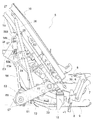
図2及び図11に示すように、伝動ケース6の下部から後方に向けて支持アーム39が延出されて、支持アーム39の後部の左右方向の横軸芯P1周りに、フロート9の後部が上下に揺動自在に支持されている。支持フレーム18から延出されたリンク機構(図示せず)にブラケット40,41が支持され、ブラケット41にポテンショメータ42が固定されて、ブラケット40の左右方向の横軸芯P2周りに中継リンク43が上下に揺動自在に支持されており、ポテンショメータ42の入力アーム42aと中継リンク43とに亘って連係ロッド44が接続されている。
[3]
Next, the raising / lowering control function and rolling control function of the
As shown in FIGS. 2 and 11, the
図11に示すように、中央のフロート9の前部の左右方向の横軸芯P3周りに連係ロッド45が前後に揺動自在に支持されており、連係ロッド45の上部の長孔45aに中継リンク43のピン43aが挿入されている。これにより、中央のフロート9の位置が連係ロッド44,45及び中継リンク43を介して、ポテンショメータ42の入力アーム42aに伝達される。
As shown in FIG. 11, a
以上の構造により、中央のフロート9が田面に接地追従するのに対して、苗植付装置5が上下動するので、ポテンショメータ42の検出値により、田面(中央のフロート9)から苗植付装置5までの高さ(植付アーム8による苗の植付深さ)が検出される。従って、ポテンショメータ42の検出値(田面(中央のフロート9)から苗植付装置5までの高さ)が設定値(設定高さ)に維持されるように、油圧シリンダ4により苗植付装置5が自動的に昇降駆動されるのであり、これにより植付アーム8による苗の植付深さが設定深さに維持される(昇降制御機能)。
With the above structure, the
図2及び図11に示すように、支持アーム39の角度を上下に変更して、横軸芯P1の位置を上下に変更することにより、前述の設定値(設定高さ)を変更することができるのであり、苗の植付深さ(設定深さ)を変更することができる。この場合、支持アーム39の角度を上下に変更すると、これに伴ってブラケット40,41を支持するリンク機構の角度も上下に変更されるのであり、支持アーム39の角度を上下に変更しても、中央のフロート9とポテンショメータ42及び中継リンク43との上下間隔は、図11に示す上下間隔から変化しない。
As shown in FIGS. 2 and 11, the set value (set height) can be changed by changing the angle of the
前項[2]の記載及び図3に示すように、フィードケース17がリンク機構3の後部下部の前後軸芯P6周りにローリング自在に支持されている(苗植付装置5がリンク機構3の後部下部の前後軸芯周りにローリング自在に支持されている)。フィードケース17に傾斜センサー48が固定されており、水平面(田面)に対する苗植付装置5の左右方向の傾斜角度が傾斜センサー48によって検出される。
As described in the preceding item [2] and as shown in FIG. 3, the
図3に示すように、リンク機構3の後部上部にローリング機構46が備えられており、ローリング機構46は、左右方向に押し引き操作される一対のワイヤ46a、ワイヤ46aを押し引き駆動するギヤ機構(図示せず)及びモータ46bを備えて構成されている。ガイドレール27の右及び左の端部にブラケット27aが固定されて、ローリング機構46のワイヤ46aとガイドレール27のブラケット27aとに亘ってバネ47が接続されており、ローリング機構46のワイヤ46aを押し引き駆動することによって、苗植付装置5がリンク機構3の後部下部の前後軸芯P6周りにローリング駆動される。
これにより、水平面(田面)に対する苗植付装置5の左右方向の傾斜角度が傾斜センサー48により検出されて、苗植付装置5が水平に維持されるように(田面と左右方向で平行に維持されるように)、ローリング機構46により苗植付装置5がリンク機構3の後部下部の前後軸芯P6周りにローリング駆動される(ローリング制御機能)。
As shown in FIG. 3, a rolling
Thereby, the inclination angle of the horizontal direction of the
図1に示すように、運転座席11の右横側に昇降レバー73が備えられており、昇降レバー73は上昇位置、中立位置、下降位置及び植付位置に操作自在に構成されている。昇降レバー73を上昇位置に操作すると、苗植付装置5(PTO軸22)に動力を伝達する植付クラッチ(図示せず)が遮断状態に操作され、前述の昇降制御機能及びローリング制御機能が停止した状態で、油圧シリンダ4により苗植付装置5が上昇駆動される。昇降レバー73を中立位置に操作すると、植付クラッチが遮断状態に操作され、昇降制御機能及びローリング制御機能が停止した状態で、油圧シリンダ4による苗植付装置5の昇降駆動が停止する。
As shown in FIG. 1, an elevating
昇降レバー73を下降位置に操作すると、植付クラッチが遮断状態に操作されて、油圧シリンダ4により苗植付装置5が下降駆動され、フロート9が田面に接地すると、前述の昇降制御機能及びローリング制御機能が作動する。昇降レバー73を植付位置に操作すると、前述の昇降レバー73を下降位置に操作した状態に加えて、植付クラッチが伝動状態に操作される。
When the elevating
[4]
次に、代掻き装置53の構造及び配置について説明する。
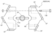
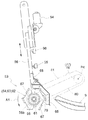
図2,3,10に示すように、右及び左の支持部材26にブラケット54がボルト31によって連結されて、右及び左のブラケット54のボス部54aに亘って支持軸55が回転自在に支持されており、支持軸55の右及び左の端部にアーム55aが連結されて、右及び左のアーム55aにピン55bが連結されている。図2,3,7に示すように、右及び左の支持部材56が備えられており、右及び左の支持部材56の下部にボス部56aが連結され、右及び左の支持部材56の上部に支持板56bが連結されており、支持板56bに長孔56cが形成され、支持板56bにピン56dが連結されている。
[4]
Next, the structure and arrangement of the
As shown in FIGS. 2, 3, and 10, a
図2,3,7に示すように、支持軸55の右及び左のピン55bが、右及び左の支持部材56の長孔56cに挿入されており、支持軸55の右及び左のピン55bと右及び左の支持部材56のピン56dとに亘ってバネ57が接続されて、支持軸55に右及び左の支持部材56が支持されている。後述するように右及び左の支持部材56に、代掻き装置53が支持されている。支持軸55の中央部付近に操作レバー58(高さ調節機構に相当)が取り付けられており、操作レバー58に対するレバーガイド59(高さ調節機構に相当)が支持フレーム18に連結されている。
As shown in FIGS. 2, 3, and 7, the right and left
これにより、図2,3,7に示すように、操作レバー58により支持軸55を回転操作して、支持軸55の右及び左のアーム55aの姿勢を上下に変更することにより、苗植付装置5に対する代掻き装置53(右及び左の支持部材56)の高さを変更することができるのであり、操作レバー58を所望の位置でレバーガイド59に係合させて固定することにより、苗植付装置5に対する代掻き装置53(右及び左の支持部材56)の高さを設定することができる。
Thus, as shown in FIGS. 2, 3, and 7, the
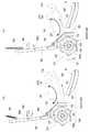
図3,5,7に示すように、代掻き装置53は、右及び左の支持部材56のボス部56aに亘って左右方向に回転自在に架設された駆動軸61、駆動軸61に連結された6個の回転体62,63,64、及び金属製の6個のカバー65等を備えて構成されており、図1,2,5に示すように、代掻き装置53はフロート9と右及び左の後輪2との間に位置している。
As shown in FIGS. 3, 5, and 7, the
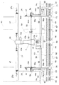
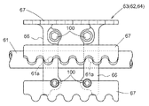
図3,5,8,9に示すように、代掻き装置53の回転体62,63,64は、代掻き装置53の駆動軸61のピン61a及びボルト100によって代掻き装置53の駆動軸61に連結される2分割の支持板66、支持板66に亘って左右方向に一体的に連結された6個のレーキ状の整地体67によって構成されている。図3,5,7に示すように、右及び左の支持部材56に亘って支持フレーム68が架設されており、代掻き装置53の回転体62,63,64の横幅と略同じ横幅を備えたカバー65が、代掻き装置53の回転体62,63,64の後側に位置するように支持フレーム68に連結されている。
As shown in FIGS. 3, 5, 8, and 9, the rotating
図3及び図5に示すように、代掻き装置53の回転体62,63,64の各々の間に、5個のリング状の隙間部69,70,71が備えられている。代掻き装置53の隙間部69は機体及び苗植付装置5の左右中央に位置して、中央のフロート9の前方に位置しており、中央の伝動ケース6の右及び左の植付アーム8の間の前方に位置している。代掻き装置53の隙間部70は右及び左の後輪2の後方に位置して、右及び左のフロート9の前方に位置しており、右及び左の伝動ケース6の右及び左の植付アーム8の間の前方に位置している。
As shown in FIGS. 3 and 5, five ring-shaped
図3及び図5に示すように、代掻き装置53の隙間部71は右及び左の後輪2の横外側の後方に位置して、右及び左のフロート9の横外端部の前方に位置しており、右及び左の伝動ケース6の右及び左の植付アーム8の横外側の前方に位置している。この場合、右及び左の前輪1の間隔と右及び左の後輪2の間隔とが、略同じものに設定されている。代掻き装置53の回転体63,64のカバー65に亘ってレーキ状の整地体72が連結されており、隙間部71の後方に整地体72が位置している。
As shown in FIGS. 3 and 5, the
図5に示すように、代掻き装置53の隙間部70の間隔L1が右及び左の後輪2のリム部2aの横幅L2よりも大きなものとなっており、代掻き装置53の隙間部70の間隔L1が右及び左の後輪2のラグ部2bの横幅L3よりも小さなものとなっている。中央の伝動ケース6の右及び左の植付アーム8(植付位置)の前方、右の伝動ケース6の左の植付アーム8(植付位置)の前方、及び左の伝動ケース6の右の植付アーム8(植付位置)の前方に、代掻き装置53の回転体62が位置している。右の伝動ケース6の右の植付アーム8(植付位置)の前方、及び左の伝動ケース6の左の植付アーム8(植付位置)の前方に、代掻き装置53の回転体63が位置している。
As shown in FIG. 5, the gap L1 of the
[5]
次に、代掻き装置53の伝動構造について説明する。
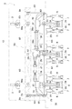
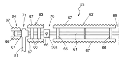
図4及び図6に示すように、支持フレーム18の左の端部に支持部材74が連結され、支持部材74に伝動軸75が回転自在に支持されて、左の伝動ケース6の入力軸32と伝動軸75とが円筒状の連結部材76により連結されており、支持ブラケット74と左の伝動ケース6とに亘って円筒状のカバー60が取り付けられて、カバー60により伝動軸75が覆われている。
[5]
Next, the transmission structure of the
As shown in FIGS. 4 and 6, a
図4,6,7に示すように、伝動軸75の端部に一方向クラッチ77(ワンウェイクラッチ)が外嵌され、一方向クラッチ77にスプロケット78が外嵌されている。代掻き装置53の駆動軸61における左の隙間部71の部分にスプロケット79が連結され、スプロケット78,79に亘って伝動チェーン80が巻回されている。一方向クラッチ77、スプロケット78,79及び伝動チェーン80を覆う伝動ケース81が備えられており、伝動ケース81が伝動軸75と代掻き装置53の駆動軸61とに亘ってベアリングを介して架設されている。
As shown in FIGS. 4, 6, and 7, a one-way clutch 77 (one-way clutch ) is fitted on the end of the
図3及び図4に示すように、支持フレーム18の右の端部にブラケット82が連結されて、ブラケット82の左右方向の横軸芯P4(図7参照)周りに、支持アーム83が上下に揺動自在に支持されており、横軸芯P4が図4及び図6に示す伝動軸23,75及び入力軸32と同芯状に配置されている。代掻き装置53の駆動軸61における右の隙間部71の部分に、支持アーム83がベアリングを介して支持されている。これにより、代掻き装置53の前後方向の位置が伝動ケース81及び支持アーム83によって決められる。
As shown in FIGS. 3 and 4, a
[6]
次に、代掻き装置53の作動状態について説明する。
前項[3]に記載のように、昇降レバー73を植付位置に操作すると、昇降制御機能及びローリング制御機能が作動して、植付クラッチが伝動状態に操作される。これにより、前項[3]に記載のように、田面(中央のフロート9)から苗植付装置5までの高さが設定値(設定高さ)に維持されるように、油圧シリンダ4により苗植付装置5及び代掻き装置53が自動的に昇降駆動され、苗植付装置5及び代掻き装置53が水平に維持されるように(田面と左右方向で平行に支持されるように)、ローリング機構46により苗植付装置5及び代掻き装置53がローリング駆動される。
[6]
Next, the operating state of the
As described in the preceding paragraph [3], by operating the
昇降レバー73を植付位置に操作すると、前述のように昇降制御機能及びローリング制御機能が作動するのに加えて、図1及び図4に示すように、エンジン49の動力がPTO軸22、入力軸28及び横送り変速機構29を介して横送り軸19に伝達され、入力軸28の動力が伝動チェーン30、伝動軸23、入力軸32、トルクリミッター33、伝動チェーン34、植付アームクラッチ24及び駆動軸35を介して植付ケース7に伝達され、植付ケース7が図2の紙面反時計方向に回転駆動されて、苗のせ台10の下部から植付アーム8が交互に苗を取り出して田面に植え付ける。これと同時に図4,6,7に示すように、入力軸32の動力が伝動軸75、一方向クラッチ77、伝動チェーン80を介して駆動軸61に伝達されており、代掻き装置53の回転体62,63,64が、植付ケース7と同様に図2及び図7の紙面反時計方向(図7の矢印A1)に回転駆動される。
When the elevating
この場合、代掻き装置53の回転体62,63,64が、機体の進行速度よりも高速で回転駆動される(右及び左の後輪2の外周部の周速度よりも代掻き装置53の回転体62,63,64の外周部の周速度が高速になるように、代掻き装置53の回転体62,63,64が高速で回転駆動される)。これにより、植付アーム8の前方の田面が代掻き装置53の回転体62,63,64によって代掻き(整地)されるのであり、代掻き装置53の回転体62,63,64から後方の苗植付装置5への泥の飛散が、カバー65によって防止される。
In this case, the rotating
図3及び図5に示すように、機体の進行に伴って、田面の泥が代掻き装置53の隙間部69,70,71を通って後方に逃げる。右及び左の後輪2により田面に溝が掘られようとするのに加えて、溝の両側に小さな泥の山が土手のように盛り上げられるような状態になると、代掻き装置53の回転体62,63の端部により田面の溝の両側の盛り上がり部分が崩されて、崩された泥が代掻き装置53の回転体62,63に邪魔されることなく、田面の溝に送り込まれるようになる。この場合、代掻き装置53の隙間部69,70を通って後方に逃げた泥がフロート9によって押圧されて整地されるのであり、代掻き装置53の隙間部71を通って後方に逃げた泥が整地体72によって整地される。
As shown in FIGS. 3 and 5, the mud on the surface escapes backward through the
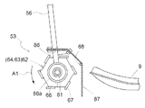
図6及び図7に示すように、代掻き装置53の駆動軸61に一方向クラッチ77を介して動力が伝達されているので、代掻き装置53の回転体62,63,64が図2及び図7の紙面反時計方向(図7の矢印A1)に先行回転する状態が無理なく許容される。図7 に示すように、右及び左の支持部材56の長孔56cの範囲で、苗植付装置5に対して代掻き装置53が上方に移動可能である。
As shown in FIGS. 6 and 7, since power is transmitted to the
前項[3]に記載のように、昇降レバー73を下降位置に操作すると、前述のように昇降制御機能及びローリング制御機能が作動するのに加えて、苗植付装置5が停止する(図6に示す入力軸32が停止する)。これにより、機体の進行に伴って田面からの抵抗により、一方向クラッチ77の作用によって、代掻き装置53の回転体62,63,64が図2及び図7の紙面反時計方向(図7の矢印A1)に回転する。
As described in the preceding paragraph [3], by operating the
[7]
次に、代掻き装置53を備えない場合について説明する。
代掻き装置53を備えない場合、図2〜図10に示すブラケット54、支持軸55、右及び左の支持部材56、バネ57、操作レバー58、レバーガイド59、支持部材74、伝動軸75、連結部材76、一方向クラッチ77、スプロケット78,79、伝動チェーン80、伝動ケース81、ブラケット82、支持アーム83等は装備しない。これ以外の構造は、図2〜図10と同じものを使用する(支持フレーム18や伝動ケース6は共用である)。
図6に示す入力軸32に代えて、図12に示すように少し短い入力軸84を左の伝動ケース6に使用して、伝動ケース6における入力軸84が対向する開口部に、蓋部材85を取り付ける。
[7]
Next, the case where the
When the
Instead of the
[発明の実施の第1別形態]
前述の[発明を実施するための最良の形態]において、一方向クラッチ77を伝動軸75に外嵌するのではなく、図6に示す代掻き装置53の駆動軸61に一方向クラッチ77を外嵌し、一方向クラッチ77にスプロケット79を外嵌するように構成してもよい。
前述の[発明を実施するための最良の形態]において、一方向クラッチ77を廃止し、動力を伝動及び遮断自在な爪式クラッチ(図示せず)を備えるように構成してもよい。
[First Alternative Embodiment of the Invention]
In the above-described [Best Mode for Carrying Out the Invention], the one-way clutch 77 is not fitted on the
In the above-mentioned [Best Mode for Carrying Out the Invention], the one-way clutch 77 may be eliminated and a pawl clutch (not shown) capable of transmitting and shutting off power may be provided.
[発明の実施の第2別形態]
前述の[発明を実施するための最良の形態][発明の実施の第1別形態]において、図13に示すように構成してもよい。
図13に示すように、一方向クラッチ77を伝動軸75(図6参照)に外嵌するのではなく、代掻き装置53の駆動軸61に複数の一方向クラッチ77を外嵌し、一方向クラッチ77に支持板66を外嵌している。これにより、回転駆動状態において代掻き装置53の回転体62,63,64が各々独立に先行回転するのであり、自由回転状態において代掻き装置53の回転体62,63,64が各々独立に回転する。
[Second Embodiment of the Invention]
In the above-mentioned [Best Mode for Carrying Out the Invention] [First Alternative Embodiment of the Invention], a configuration as shown in FIG.
As shown in FIG. 13, the one-way clutch 77 is not externally fitted to the transmission shaft 75 (see FIG. 6), but a plurality of one-
[発明の実施の第3別形態]
前述の[発明を実施するための最良の形態][発明の実施の第1別形態][発明の実施の第2別形態]において、図14に示すように構成してもよい。
図14に示すように、代掻き装置53の回転体62,63の支持板66よりも、代掻き装置53の回転体64の支持板66を小さいものに構成して、代掻き装置53の回転体62,63の外径よりも、代掻き装置53の回転体64の外径が小さなものになるように構成している。
[Third Another Embodiment of the Invention]
In the above-mentioned [Best Mode for Carrying Out the Invention] [First Alternative Embodiment of the Invention] [Second Alternative Embodiment of the Invention], it may be configured as shown in FIG.
As shown in FIG. 14, the
この場合、代掻き装置53の回転体62,63の外径よりも代掻き装置53の回転体64の外径が小さい状態、及び代掻き装置53の回転体62,63,64の外径が同じである状態において、代掻き装置53の回転体62,63の整地体67の数(6個)よりも、代掻き装置53の回転体64の整地体67の数を少ないものに構成してもよい(例えば3個又は2個)。
In this case, the outer diameter of the
[発明の実施の第4別形態]
前述の[発明を実施するための最良の形態][発明の実施の第1別形態]〜[発明の実施の第3別形態]において、図15に示すように構成してもよい。
図15に示すように、金属製のカバー65(図3,5,7参照)を廃止し、右及び左の支持部材56に亘って支持フレーム86を架設し、代掻き装置53の回転体62,63,64の横幅と略同じ横幅を備えた折れ曲がり自在なゴム製のカバー87を、代掻き装置53の回転体62,63,64の後側に位置するように支持フレーム86に連結している。伝動ケース81及び支持アーム83(図3及び図4参照)に亘って支持ロッド88を架設しており、カバー87を支持ロッド88に当て付けて、カバー87が代掻き装置53の回転体62,63,64に干渉するのを防止している。
[Fourth Embodiment of the Invention]
In the above-mentioned [Best Mode for Carrying Out the Invention] [First Alternative Embodiment of the Invention] to [Third Alternative Embodiment of the Invention], it may be configured as shown in FIG.
As shown in FIG. 15, the metal cover 65 (see FIGS. 3, 5, and 7) is abolished, a
前項[3]に記載のように、支持アーム39(図2及び図11参照)の角度を上下に変更して、横軸芯P1の位置を上下に変更することにより、設定値(設定高さ)(苗の植付深さ(設定深さ))を変更する場合、設定値(設定高さ)(苗の植付深さ(設定深さ))を最大値(最浅植)に設定した状態で、前項[4]に記載のように、操作レバー58(図3及び図7参照)により苗植付装置5に対する代掻き装置53(右及び左の支持部材56)の高さを最上昇位置に設定しても、カバー87の下端がフロート9の底面よりも下方に位置するように、カバー87が少し長めに構成されている。
As described in [3] above, by changing the angle of the support arm 39 (see FIGS. 2 and 11) up and down and changing the position of the horizontal axis P1 up and down, the set value (set height) ) When changing (planting depth of seedling (set depth)), set value (set height) (planting depth of seedling (set depth)) was set to the maximum value (shallowest planting) In the state, as described in the preceding item [4], the height of the scraping device 53 (right and left support members 56) with respect to the
[発明の実施の第5別形態]
前述の[発明を実施するための最良の形態][発明の実施の第1別形態]〜[発明の実施の第4別形態]において、図16(イ)(ロ)に示すように構成してもよい。
図16(イ)(ロ)に示すように、代掻き装置53の駆動軸61の右及び左の端部に、回転促進体89を連結している。回転促進体89は8本の棒部材89aが代掻き装置53の駆動軸61に放射状に連結され、円盤部材89bが代掻き装置53の駆動軸61に連結されて構成されている。回転促進体89(棒部材89a)の外径が代掻き装置53の回転体62,63,64の外径よりも大きなものに構成されており、回転促進体89の円盤部材89bの外径が代掻き装置53の回転体62,63,64の外径と略同じものに構成されている。
[Fifth Embodiment of the Invention]
In the above-mentioned [Best Mode for Carrying Out the Invention] [First Alternative Embodiment of the Invention] to [Fourth Alternative Embodiment of the Invention], it is configured as shown in FIGS. May be.
As shown in FIGS. 16A and 16B, a
これにより、自由回転状態を設定した状態において、機体の進行に伴う田面からの抵抗が代掻き装置53の回転体62,63,64に掛かるのに加えて、機体の進行に伴う田面からの抵抗が回転促進体89(棒部材89a)から代掻き装置53の回転体62,63,64に掛かり、代掻き装置53の回転体62,63,64の回転が促進される。機体の進行に伴って代掻き装置53の回転体62,63,64の端部から横外側に泥の流れが発生しても、この泥の流れが回転促進体89の円盤部材89bによって抑えられる。
As a result, in a state where the free rotation state is set, in addition to the resistance from the surface accompanying the advancement of the airframe being applied to the
[発明の実施の第6別形態]
前述の[発明を実施するための最良の形態][発明の実施の第1別形態]〜[発明の実施の第5別形態]において、図17に示すように構成してもよい。
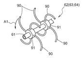
六角状の支持板66及びレーキ状の整地体67(図3,5,8,9参照)により、代掻き装置53の回転体62,63,64を構成するのではなく、図17に示すように、代掻き装置53の駆動軸61に複数個のボス部91を連結し、円弧状に曲がった4本の棒部材90をボス部91の各々に放射状に連結して、代掻き装置53の回転体62,63,64を構成している。この場合、代掻き装置53の回転体62,63,64が、矢印A1の方向に回転駆動されるように構成する。
[Sixth Embodiment of the Invention]
In the above-mentioned [Best Mode for Carrying Out the Invention] [First Alternative Embodiment of the Invention] to [Fifth Alternative Embodiment of the Invention], it may be configured as shown in FIG.
The
[発明の実施の第7別形態]
前述の[発明を実施するための最良の形態][発明の実施の第1別形態]〜[発明の実施の第6別形態]において、図18に示すように構成してもよい。
図18に示すように、代掻き装置53の中央付近の左右方向の横軸芯P5周りに、所定の横幅を備えた検出アーム92を上下に揺動自在に支持し、検出アーム92とポテンショメータ42の入力アーム42aとに亘ってワイヤ93を接続している。
[Seventh Embodiment of the Invention]
In the above-mentioned [Best Mode for Carrying Out the Invention] [First Alternative Embodiment of the Invention] to [Sixth Alternative Embodiment of the Invention], it may be configured as shown in FIG.
As shown in FIG. 18, a
これにより、例えば田面の泥が代掻き装置53の回転体62の付近に絡みついて盛り上がると、泥により検出アーム92が上方に揺動操作され、ワイヤ93が引き操作されて、ポテンショメータ42の入力アーム42aが図18の紙面反時計方向に揺動操作される。このような状態になると、田面(中央のフロート9)に対して苗植付装置5が下降した状態と同じ状態になるので、ポテンショメータ42の検出値(田面(中央のフロート9)から苗植付装置5までの高さ)が設定値(設定高さ)に維持されるように、油圧シリンダ4により苗植付装置5が自動的に上昇駆動されて、田面の泥が代掻き装置53の回転体62の付近に絡みついて盛り上がる状態が抑えられる。
Thereby, for example, when the mud on the surface entangles and rises in the vicinity of the
[発明の実施の第8別形態]
前述の[発明を実施するための最良の形態][発明の実施の第1別形態]〜[発明の実施の第7別形態]において、図19に示すように構成してもよい。
図19に示すように、操作レバー58及びレバーガイド59(図3及び図7参照)を廃止し、右及び左の支持部材56を昇降駆動する電動モータ94(高さ調節機構に相当)、苗植付装置5に対する右及び左の支持部材56の最下降位置を検出する下限スイッチ95及び苗植付装置5に対する右及び左の支持部材56の最上昇位置を検出する上限スイッチ96を備えている。これにより、苗植付装置5に対する代掻き装置53(右及び左の支持部材56)の高さを、電動モータ94によって変更する(最下降位置と最下降位置から少し上側の位置との間の範囲)。
[Eighth Embodiment of the Invention]
In the above-mentioned [Best Mode for Carrying Out the Invention] [First Alternative Embodiment of the Invention] to [Seventh Alternative Embodiment of the Invention], it may be configured as shown in FIG.
As shown in FIG. 19, the
この場合、植付クラッチが伝動状態に操作されると、電動モータ94により代掻き装置53が田面を代掻き(整地)する高さ(最下降位置と最下降位置から少し上側の位置との間の範囲)に下降駆動され、植付クラッチが遮断状態に操作されると、電動モータ94により代掻き装置53が最上昇位置(フロート9が田面に接地していても代掻き装置53が田面よりも上方に位置する状態)に上昇駆動されるように構成してもよい。
In this case, when the planting clutch is operated in the transmission state, the height (range between the lowest position and the position slightly above the lowest position) where the
[発明の実施の第9別形態]
前述の[発明を実施するための最良の形態][発明の実施の第1別形態]〜[発明の実施の第8別形態]において、図20(イ)(ロ)に示すように構成してもよい。
図20(イ)に示すように、伝動チェーン80を少し緩めにスプロケット78,79に巻回し、伝動チェーン80の上側に板バネ状のテンショナー97を配置する。右及び左の支持部材56を上方に付勢するバネ98を備え、上下に揺動自在なストッパー部材99を備えている。
[Ninth Embodiment of the Invention]
In the above-mentioned [Best Mode for Carrying Out the Invention] [First Alternative Embodiment of the Invention] to [Eighth Alternative Embodiment of the Invention], it is configured as shown in FIGS. May be.
As shown in FIG. 20A, the
これにより、植付クラッチが伝動状態に操作されて、図20(イ)の矢印A2の方向に伝動チェーン80が回転駆動されると、ストッパー部材99が下方に揺動操作されて、伝動チェーン80の張力及びテンショナー97の押圧力により、図20(ロ)に示すようにバネ98に抗して代掻き装置53が下降駆動される(代掻き装置53が田面に接地して、代掻き装置53により田面が代掻き(整地)される状態)。次に植付クラッチが遮断状態に操作されて、伝動チェーン80が停止し、伝動チェーン80の張力が消えると、バネ98により代掻き装置53が上昇駆動される(フロート9が田面に接地していても代掻き装置53が田面よりも上方に位置する状態)。
As a result, when the planting clutch is operated in the transmission state and the
前述のように代掻き装置53が上昇駆動されると、右及び左の支持部材56の凸部56eがストッパー部材99を押し上げてストッパー部材99に乗り、代掻き装置53が上昇駆動された状態に保持される。次に植付クラッチが伝動状態に操作されると、ストッパー部材99が下方に揺動操作されて、伝動チェーン80の張力及びテンショナー97の押圧力により、バネ98に抗して代掻き装置53が下降駆動される(代掻き装置53が田面に接地して、代掻き装置53により田面が代掻き(整地)される状態)。
When the
1 前輪
2 後輪
3 リンク機構
4 油圧シリンダ
5 苗植付装置
6 伝動ケース
8 植付機構
9 フロート
18 支持フレーム
45 連係ロッド
53 代掻き装置
58,59,94 高さ調節機構
62,64,64 回転体
65,87 カバー
67 整地体
69,70,71 隙間部
1
4
6
18 Support frame
45
Claims (9)
左右方向に配置された支持フレームに伝動ケースを連結して、前記伝動ケースの後部に植付機構を備え、前記伝動ケースの下側にフロートの後部を上下に揺動自在に支持して、前記苗植付装置を構成し、
前記フロートの前部に支持された連係ロッドを、前記フロートの前部への支持箇所から前記支持フレームの後側を通して上方に延出して、該連係ロッドによって田面から前記苗植付装置までの高さを検出するように構成し、
田面から前記苗植付装置までの高さが設定値に維持されるように、前記油圧シリンダにより苗植付装置が自動的に昇降駆動されるように構成してある乗用型田植機。 A link mechanism is provided at the rear part of the machine body supported by the front wheel and the rear wheel, a hydraulic cylinder for driving the link mechanism to move up and down is provided, and the seedling planting device is supported by the link mechanism,
A transmission case is connected to a support frame arranged in the left-right direction, and a rear portion of the transmission case is provided with a planting mechanism, and a rear portion of the float is supported on the lower side of the transmission case so as to be swingable up and down. Configure the seedling planting device,
The linkage rod which is supported on the front portion of the front Symbol float, and extending upwardly from the support portion to the front portion of the float through the rear side of the support frame, the seedling planting from paddy by該連engagement rod Configure to detect the height to the device,
A riding type rice transplanter configured such that a seedling planting device is automatically driven up and down by the hydraulic cylinder so that a height from a rice field to the seedling planting device is maintained at a set value.
Priority Applications (1)
| Application Number | Priority Date | Filing Date | Title |
|---|---|---|---|
| JP2004166055A JP4484591B2 (en) | 2004-06-03 | 2004-06-03 | Ride type rice transplanter |
Applications Claiming Priority (1)
| Application Number | Priority Date | Filing Date | Title |
|---|---|---|---|
| JP2004166055A JP4484591B2 (en) | 2004-06-03 | 2004-06-03 | Ride type rice transplanter |
Publications (3)
| Publication Number | Publication Date |
|---|---|
| JP2005341881A JP2005341881A (en) | 2005-12-15 |
| JP2005341881A5 JP2005341881A5 (en) | 2007-07-12 |
| JP4484591B2 true JP4484591B2 (en) | 2010-06-16 |
Family
ID=35494809
Family Applications (1)
| Application Number | Title | Priority Date | Filing Date |
|---|---|---|---|
| JP2004166055A Expired - Fee Related JP4484591B2 (en) | 2004-06-03 | 2004-06-03 | Ride type rice transplanter |
Country Status (1)
| Country | Link |
|---|---|
| JP (1) | JP4484591B2 (en) |
Families Citing this family (21)
| Publication number | Priority date | Publication date | Assignee | Title |
|---|---|---|---|---|
| JP4389122B2 (en) * | 2006-02-27 | 2009-12-24 | 井関農機株式会社 | Seedling transplanter |
| JP4676360B2 (en) * | 2006-03-08 | 2011-04-27 | 三菱農機株式会社 | Transplanter |
| JP2007236263A (en) * | 2006-03-08 | 2007-09-20 | Mitsubishi Agricult Mach Co Ltd | Transplanter |
| JP4773263B2 (en) * | 2006-05-09 | 2011-09-14 | 株式会社クボタ | Paddy field machine |
| JP4653713B2 (en) * | 2006-09-26 | 2011-03-16 | 株式会社クボタ | Paddy field machine |
| JP4769212B2 (en) * | 2007-03-12 | 2011-09-07 | 株式会社クボタ | Paddy field machine |
| JP4914254B2 (en) * | 2007-03-12 | 2012-04-11 | 株式会社クボタ | Paddy field machine |
| JP4773388B2 (en) * | 2007-03-22 | 2011-09-14 | 株式会社クボタ | Paddy field machine |
| JP4773389B2 (en) * | 2007-03-26 | 2011-09-14 | 株式会社クボタ | Paddy field machine |
| JP4914263B2 (en) * | 2007-03-26 | 2012-04-11 | 株式会社クボタ | Paddy field machine |
| JP4880728B2 (en) * | 2009-07-17 | 2012-02-22 | 株式会社クボタ | Leveling rotor structure |
| JP5385828B2 (en) * | 2010-03-12 | 2014-01-08 | 株式会社クボタ | Leveling rotor structure and leveling rotor |
| JP5337087B2 (en) * | 2010-03-19 | 2013-11-06 | 三菱農機株式会社 | Leveling rotor |
| JP5261456B2 (en) * | 2010-09-06 | 2013-08-14 | 株式会社クボタ | Paddy field machine |
| JP5418537B2 (en) * | 2011-04-27 | 2014-02-19 | 井関農機株式会社 | Passenger rice transplanter |
| JP5803278B2 (en) * | 2011-05-27 | 2015-11-04 | 井関農機株式会社 | Seedling transplanter |
| JP5825859B2 (en) * | 2011-06-06 | 2015-12-02 | 株式会社クボタ | Paddy field machine |
| JP5715013B2 (en) * | 2011-09-12 | 2015-05-07 | 株式会社クボタ | Ride type paddy field work machine |
| JP5621893B2 (en) * | 2013-08-22 | 2014-11-12 | 井関農機株式会社 | Working machine |
| JP7081649B1 (en) * | 2020-11-27 | 2022-06-07 | 井関農機株式会社 | Riding type seedling transplanter |
| CN113287398B (en) * | 2021-06-11 | 2024-06-28 | 河北省农业机械化研究所有限公司 | Alternate planting machine for sweet potato seedlings |
Family Cites Families (8)
| Publication number | Priority date | Publication date | Assignee | Title |
|---|---|---|---|---|
| JPH06237618A (en) * | 1993-02-16 | 1994-08-30 | Kubota Corp | Paddy transplanter float structure |
| JPH09205813A (en) * | 1996-01-29 | 1997-08-12 | Mitsubishi Agricult Mach Co Ltd | Pudding device of transplanter |
| JPH09294407A (en) * | 1996-05-02 | 1997-11-18 | Kubota Corp | Transplant machine |
| JPH1056835A (en) * | 1996-08-20 | 1998-03-03 | Mitsubishi Agricult Mach Co Ltd | Transplanter with simultaneous puddling function |
| JPH11266604A (en) * | 1998-03-24 | 1999-10-05 | Mitsubishi Agricult Mach Co Ltd | Transplanter |
| JP3251238B2 (en) * | 1998-05-29 | 2002-01-28 | 三菱農機株式会社 | Transplant machine |
| JP3443359B2 (en) * | 1999-03-25 | 2003-09-02 | 株式会社クボタ | Paddy field machine |
| JP2000300018A (en) * | 1999-04-15 | 2000-10-31 | Kubota Corp | Rice transplanter lifting control |
-
2004
- 2004-06-03 JP JP2004166055A patent/JP4484591B2/en not_active Expired - Fee Related
Also Published As
| Publication number | Publication date |
|---|---|
| JP2005341881A (en) | 2005-12-15 |
Similar Documents
| Publication | Publication Date | Title |
|---|---|---|
| JP4484591B2 (en) | Ride type rice transplanter | |
| JP2005341881A5 (en) | ||
| JP4350102B2 (en) | Ride type rice transplanter | |
| JP5134283B2 (en) | Paddy field machine | |
| JP5033022B2 (en) | Paddy field machine | |
| JP4835248B2 (en) | Seedling transplanter | |
| JP4769282B2 (en) | Rice transplanter | |
| JP5276545B2 (en) | Paddy field work vehicle | |
| JP4537921B2 (en) | Rice transplanter | |
| JP4887564B2 (en) | Seedling planting machine | |
| JP5551901B2 (en) | Ride type direct seeding machine | |
| JP4769212B2 (en) | Paddy field machine | |
| JP5825859B2 (en) | Paddy field machine | |
| JP2011139670A (en) | Paddy field working machine | |
| JP5262225B2 (en) | Riding seedling planter | |
| JP4484754B2 (en) | Rice transplanter | |
| JP2008005744A (en) | Seedling planting machine | |
| JP4168529B2 (en) | Seedling transplanter | |
| JP2014166161A (en) | Paddy field working machine | |
| JPH09248024A (en) | Farm work machine | |
| JP3570948B2 (en) | Riding rice transplanter | |
| JP5136464B2 (en) | Seedling planting machine | |
| JP7113738B2 (en) | work machine | |
| JP7109357B2 (en) | work machine | |
| JP2020130073A (en) | Paddy field work machine |
Legal Events
| Date | Code | Title | Description |
|---|---|---|---|
| A621 | Written request for application examination |
Free format text: JAPANESE INTERMEDIATE CODE: A621 Effective date: 20070516 |
|
| A521 | Request for written amendment filed |
Free format text: JAPANESE INTERMEDIATE CODE: A523 Effective date: 20070528 |
|
| A977 | Report on retrieval |
Free format text: JAPANESE INTERMEDIATE CODE: A971007 Effective date: 20090630 |
|
| A131 | Notification of reasons for refusal |
Free format text: JAPANESE INTERMEDIATE CODE: A131 Effective date: 20090702 |
|
| A521 | Request for written amendment filed |
Free format text: JAPANESE INTERMEDIATE CODE: A523 Effective date: 20090826 |
|
| TRDD | Decision of grant or rejection written | ||
| A01 | Written decision to grant a patent or to grant a registration (utility model) |
Free format text: JAPANESE INTERMEDIATE CODE: A01 Effective date: 20100318 |
|
| A01 | Written decision to grant a patent or to grant a registration (utility model) |
Free format text: JAPANESE INTERMEDIATE CODE: A01 |
|
| A61 | First payment of annual fees (during grant procedure) |
Free format text: JAPANESE INTERMEDIATE CODE: A61 Effective date: 20100323 |
|
| R150 | Certificate of patent or registration of utility model |
Free format text: JAPANESE INTERMEDIATE CODE: R150 |
|
| FPAY | Renewal fee payment (event date is renewal date of database) |
Free format text: PAYMENT UNTIL: 20130402 Year of fee payment: 3 |
|
| FPAY | Renewal fee payment (event date is renewal date of database) |
Free format text: PAYMENT UNTIL: 20130402 Year of fee payment: 3 |
|
| FPAY | Renewal fee payment (event date is renewal date of database) |
Free format text: PAYMENT UNTIL: 20140402 Year of fee payment: 4 |
|
| LAPS | Cancellation because of no payment of annual fees |