JP4887564B2 - Seedling planting machine - Google Patents
Seedling planting machine Download PDFInfo
- Publication number
- JP4887564B2 JP4887564B2 JP2001007836A JP2001007836A JP4887564B2 JP 4887564 B2 JP4887564 B2 JP 4887564B2 JP 2001007836 A JP2001007836 A JP 2001007836A JP 2001007836 A JP2001007836 A JP 2001007836A JP 4887564 B2 JP4887564 B2 JP 4887564B2
- Authority
- JP
- Japan
- Prior art keywords
- leveling
- auger
- float
- seedling planting
- seedling
- Prior art date
- Legal status (The legal status is an assumption and is not a legal conclusion. Google has not performed a legal analysis and makes no representation as to the accuracy of the status listed.)
- Expired - Fee Related
Links
Images


Abstract
Description
【0001】
【発明の属する技術分野】
この発明は、フロートの前側に均平装置を配置した苗植機に関し、特に、乗用車体の後部に装着される苗植装置において、苗植付けを行う植付土壌面を均平装置によって均平させるもので、枕地のように土壌面の荒れた場所での苗の植付けを行う場合に有効に利用される。
【0002】
【従来の技術】
苗植装置のフロートの前側に均平装置を設ける技術は知られている。
【0003】
【発明が解決しようとする課題】
苗植装置のフロート前の均平装置は、凸凹の著しい荒れた土壌面、例えば畦際や枕地等で使用されて、通常の比較的滑面な土壌面では使用しない。このため、この均平装置を苗植装置に対して昇降可能に切替るように構成する。しかしながら、均平装置を非作用位置へ上昇した状態でも伝動回転の状態にしたままで苗植作業を行うと、苗植装置1と干渉したりして危険である。
【0004】
【課題を解決するための手段】
請求項1に記載の発明は、前車輪(12)と後車輪(13)を備える車体(11)の後部にリフトリンク(19)を介して中央のセンタフロート(2)と左右両側のサイドフロート(28)を装備した苗植装置(1)を昇降自在に装着した苗植機において、該センタフロート(2)の前側に配置した均平装置(3)を設け、操作レバー(51)を均平作用を行う均平作用位置(E)と収納位置(F)とに切替自在に設けると共に、苗植装置(1)及び均平装置(3)への伝動を共に入り切りするPTOクラッチ(40)と均平装置(3)への伝動を入り切りするクラッチ(7)とを設け、操作レバー(51)を収納位置(F)へ操作すると均平装置(3)を非作業位置へ上昇させると共にクラッチ(7)を切り、操作レバー(51)を均平作用位置(E)へ操作すると均平装置(3)を均平作業位置へ下動させると共にクラッチ(7)を入りにする構成とし、後車輪(13)の踏跡を滑走する位置にサイドフロート(28)を配置し、後車輪(13)とサイドフロート(28)の間に櫛状のレーキ(57)を設け、該レーキ(57)は、サイドフロート(28)の均平幅よりも広幅で、下端をサイドフロート(28)の底面の下方に配置し、均平装置(3)を覆うカバー(6)の後端縁部を、センターフロート(2)の前側を覆う機体平面視で山形状に形成した苗植機とする。
【0005】
【0006】
【発明の効果】
レーキ57により、苗植付時には、後車輪13で掻き上げられた泥土を掻き均し、更にサイドフロート28により均平して、苗植付精度を向上させることができる。レーキ57は、苗植機格納時は苗植装置1の重心位置を支持して、苗植装置1のスタンドとすることができる。
【0007】
しかも、均平装置3を覆うカバー6の後端縁部を、センターフロート2の前側を覆う機体平面視で山形状に形成したので、均平装置3によって掻き出される土壌は、センターフロート2とサイドフロート28の間隔部に流動案内され易くなる。
【0008】
【発明の実施の形態】
この発明は、主としてトラクタ等の車体の後部に装着して苗植作業を行う乗用形態で、多条植形態の苗植装置に利用できる。この苗植装置を支持して滑走するフロートの前側に均平装置である均平オーガを配置して、この均平オーガにより土壌面の凹凸を掻き均して、該フロートによる滑走均平を円滑に行わせる形態として実施できる。
【0009】
これら苗植機に構成の概要を図例に基づいて説明する。
車体11は前車輪12と後車輪13とを有し、ステアリングポスト14のステアリングハンドル15の操作で操向できる。この後部のエンジンルームに搭載のエンジンによって駆動走行すると共に、このエンジンルーム上に運転席16が設けられ、左右両側部には前後方向に渡るサイドフロア17が配置される。18は前車輪12の外側部に配置される補助苗載台で、苗植装置1へ供給するための補給用の苗を搭載できる。
【0010】
車体11の後部には、平行リンク機構からなり昇降自在のリフトリンク19が、リフトシリンダ20の伸縮によって昇降されるように連結され、この後端のリンクヒッチ21に苗植装置1のヒッチ22が着脱できる。23はリフトリンク19の前端に設けられたリフトアームで、リフトシリンダ20によって油圧伸縮されるピストン24が連結されて昇降される。
【0011】
苗植装置1は、多条植形態で、苗植フレーム25の上側に後下がり傾斜の苗タンク26が左右横方向へ移動可能に配置され、後部にはこの各苗タンク26の後下端に繰り出される苗を分離して植付ける苗植付装置27を配置する。又、この苗植フレーム25の下側には、中央部にセンタフロート2を、この左右両側にはサイドフロート28を配置して、苗植作業時に土壌面に苗植装置1を支持して滑走すると共に、各苗植付装置27による苗植付位置を均平にするものである。
【0012】
これら各フロート2,28は後部を苗植フレーム25に対してフロート支持軸29で上下回動自在に支持され、このうちセンタフロート2は連動機構30で前記リフトシリンダ20の油圧制御弁31に連結されて、苗植装置1の昇降制御を行って苗植付け深さを一定に維持させる。即ち、センタフロート2が大きく上動すると油圧制御弁31によりリフトシリンダ20を伸ばして苗植装置1を上動させ、又、逆に大きく下動すると苗植装置1を下動させて、土壌の深さ変化に拘らず苗植付け深さを一定に維持する。
【0013】
前記苗植フレーム25は、ヒッチ22を有するヒッチフレーム32の後端にローリング自在に連結されている。この苗植フレーム25の前側には平行リンク機構の昇降リンク34を介して、均平オーガ3をオーガ軸38回りに回転伝動可能に軸装のオーガ伝動ケース33が装着される。このオーガ軸38の両端を軸装するオーガ伝動ケース33とオーガアーム35は、ハンドル36で伸縮される伸縮杆37を介して苗植フレーム25の上下搖動可能のアーム46に対して昇降調節される。6は均平オーガ3の後上部を覆うオーガカバーである。
【0014】
これら苗植装置1や均平オーガ3等の伝動は、車体11側のPTO軸39、PTOクラッチ40を経て、伸縮軸及び自在継手等を介する伝動軸41で苗植フレーム25内の伝動機構に伝動される。この苗植フレーム25内の苗植伝動軸42から苗植装置1各部へ連動されると共に、伸縮軸や自在継手等を有する伝動軸43を介してオーガ伝動ケース33の入力軸44へ伝動される。各苗植装置1では、苗タンク26が横方向へ往復移動されると共に、移動端では各苗繰出ベルト45が間歇駆動される。又、苗植付機構27が伝動されて、苗植付爪を楕円形状の植付軌跡Dに作動させて、苗タンク26の下端部に繰り出されるマット状の苗から数本宛の苗を分離して、フロート2,28で均平される土壌面Cに植え付けることができる。
【0015】
ここにおいて、苗植装置1を支持して滑走するフロート2の前側に昇降可能に設けられる均平オーガ3の伝動を、この均平オーガ3の非作用位置への上昇に連動して切りにする苗植機の均平装置の構成とする。
【0016】
これによって、苗植作業時に均平オーガ3による土壌均平を行うときは、均平オーガ3を非作用位置から下降させて伝動駆動することによって、フロート2前の荒れた土壌面が均平オーガ3によって横方向へ掻き均されて、フロート2による滑走均平を円滑に行わせる。又、均平オーガ3を非作用位置へ上昇すると均平作用が行われなくなると共に、この上昇によって均平オーガ3の伝動が自動的に断たれて回転が停止され、伝動の切り忘れをなくすることができ、的確な操作、及び操作性を高めることができる。
【0017】
又、苗植装置1を支持して滑走するフロート2の前側に設けられる均平オーガ3の軸受ハブ4の外径Aを、この均平オーガ3の駆動軸部となるオーガ軸部5の軸径Bと略同径乃至小径に形成した苗植機の均平装置の構成とする。
【0018】
これによって、均平オーガ3は左右両端部を軸受ハブ4に軸支された状態で回転されて、フロート2前部の土壌面を横方向へ掻き均すため、この掻き寄せられた土壌の一部が横端の軸受ハブ4を越えて外側方へ押し出され易くなる。このような押出土壌等の流動において、均平オーガ3のオーガ軸受部5の軸径Bが軸受ハブ4の外径Aと同径乃至これよりも大径に形成されているため、この軸受ハブ4による流動抵抗を受けることが少なくなり、泥はけを速やかに行わせることができ、円滑な均平を行わせることができる。
【0019】
ここに、均平オーガ3は、センタフロート2の前側に設けられて、回転によって土壌面Cを中央部から左右両側へ掻き出すようにオーガ軸部5周りに左右対称状に形成される。この均平オーガ3によって掻き出される凸部の土壌は、土壌面の凹部を埋めて均平に掻き均しながら後部のセンタフロート2とサイドフロート28との間隔部に流動案内させる。前記オーガカバー6の後端縁部はこのセンタフロート2の前側を覆うように山形状に形成されて、左右への泥土の流れが行われ易くしている。
【0020】
前記昇降リンク34は、苗植フレーム25に一体のブラケット47に対して上下回動軸48周りにバネ49に抗して上下回動しうる支持構成としている。この昇降リンク34にはワイヤー50が連結されて、車体11側の操作レバー51でバネ49に抗して下降させることができる。即ち、操作レバー51は作用位置Eと収納位置Fとに切替できて、作用位置Eでは、ワイヤー50を引上げてバネ49に抗して均平オーガ3を均平作業位置に下動させることができ、収納位置Fでは、ワイヤー50を緩めてバネ49の付勢力により均平オーガ3を非作業位置へ上昇させる。
【0021】
又、前記オーガ伝動ケース33の上部のクラッチ軸10上には、カムクラッチ8がバネ9によって常時噛合しうる方向に弾発して設けられ、均平オーガ3への伝動を入り切りするオーガクラッチ7が構成される。このカムクラッチ8には、ワイヤー52でバネ53に抗して操作されるカムピン54が作用できる。バネ53の弾発力でカムピン54をこのカムクラッチ8に作用させると、入力軸44側から伝動回転されるカムクラッチ8がバネ9に抗して移動されて、オーガクラッチ7を切りにし、ワイヤー52を引いてカムピン54をカムクラッチ8から外すとバネ9に押されてオーガクラッチ7を入りにする。このワイヤー52は前記操作レバー51に連結して、この操作レバー51を収納位置Fへ操作するとワイヤー52を緩めてカムピン54をバネ53によってカムクラッチ8側へ作動させて、オーガクラッチ7を切りにし、逆に、作用位置Eへ操作するとオーガクラッチ7を入りにすることができる。
【0022】
このため、操作レバー51を収納位置Fにすると、均平オーガ3の伝動を停止し、作用位置Eにすると、作業位置へ下降させて、伝動を行って均平作用を行わせる。
前記オーガ軸38のオーガ伝動ケース33やオーガアーム35による軸受は、これらオーガ伝動ケース33やオーガアーム35の下端部の軸受ハブ4部に対してベアリング55を介して軸受される。この軸受ハブ4は、オーガ伝動ケース33やオーガアーム35の軸方向の厚さよりも大きく張出形成されるが、この軸受ハブ4部の外径Aをオーガ軸部5の軸径Bと略同径に形成している。又、この軸受ハブ4の外径Aを軸径Bよりも小さく形成することもできる。56はオーガ軸38を嵌合させて軸受けするギヤである。
【0023】
均平オーガ3はオーガ伝動ケース33内のギヤ伝動で回転され、センタフロート2前側の土壌面Cを掻き均す。この掻き均される土壌は筒状のオーガ軸部5の外周面に沿って左右両側方へ移動案内されて、軸受ハブ4の下側を外側へ流動される。このとき軸受ハブ4の径が小さいため掻き寄せられる泥土やわら屑等は、オーガ軸部5から軸受ハブ4面に速やかに流れて、後方へ流動される。
【0024】
又、前記オーガ軸部5は、均平オーガ3を一体に巻き付ける円筒状形態であるが、このオーガ軸部5の軸径Bはできるだけ大きい径とすることによって、均平作用時の泥押効果を高められる。この軸径Bは均平オーガ3の回転径の略二分の一乃至これよりも大きく形成している。
【0025】
図9、図10において、上例と異なる点を説明する。前記苗植装置1のセンタフロート2は、車体11の左右の後車輪13間に対応して設けられるが、サイドフロート28は後車輪13の踏跡を滑走するように配置されていて、これら後車輪13と後側のサイドフロート28との間に櫛状のレーキ57を設けて、後車輪13が踏跡の土壌面を代掻きする。このレーキ57は、サイドフロート28の均平幅よりも広幅に設定し、このレーキ57の下端をサイドフロート28の底面よりも下方に位置するように設定して、前記苗植フレーム25に装着する。又、このレーキ57は、ブラケット58で該苗植フレーム25に対して支軸59の周りに上下回動自在に設けられて、レバー60の操作で上下調節される。61はこのレバーガイドで、調節位置を係止できる。
【0026】
苗植付時は、このレーキ57によって、後車輪13で掻き上げられた泥土を掻き均し、更にサイドフロート28により均平して、苗植付精度を向上させると共に、苗植機格納時は苗植装置1の重心位置を床面に支持して、苗植装置1のスタンドとすることができる。
【図面の簡単な説明】
【図1】 均平オーガ部の一部の側面図。
【図2】 その平面図。
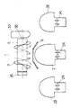
【図3】 その一部の拡大正面図。
【図4】 その側面図。
【図5】 その苗植装置部の側面図。
【図6】 その均平オーガ部の配置平面図。
【図7】 その伝動機構部の側面図。
【図8】 その苗植機の平面図。
【図9】 その一部の別実施例を示す苗植装置部の側面図。
【図10】 その一部の正面図。
【符号の説明】
1 苗植装置
2 フロート
3 均平装置(均平オーガ)
7 クラッチ
11 車体
19 リフトリンク
40 PTOクラッチ
51 操作レバー
E 均平作用位置
F 収納位置[0001]
BACKGROUND OF THE INVENTION
TECHNICAL FIELD The present invention relates to a seedling planting machine in which a leveling device is arranged on the front side of a float, and in particular, in a seedling planting device mounted on the rear part of a passenger car body, the planted soil surface for seedling planting is leveled by the leveling device. It is effective when planting seedlings in places with rough soil surfaces such as headlands.
[0002]
[Prior art]
A technique for providing a leveling device on the front side of a float of a seedling planting device is known.
[0003]
[Problems to be solved by the invention]
The leveling device before the float of the seedling planting device is used on a rough and rough soil surface, such as a shoreline or a headland, and is not used on a normal relatively smooth soil surface. For this reason, this leveling device is configured to be switched up and down with respect to the seedling planting device. However, if the seedling planting operation is performed while the leveling device is raised to the non-operating position and remains in the transmission rotation state, it may be dangerous because it interferes with the
[0004]
[Means for Solving the Problems]
According to the first aspect of the present invention, the center center float (2) and the left and right side floats are disposed on the rear portion of the vehicle body (11) including the front wheel (12) and the rear wheel (13) via a lift link (19). In a seedling planter equipped with a seedling planting device (1) equipped with (28) so as to be able to move up and down, a leveling device (3) arranged on the front side of the center float (2) is provided, and the operation lever (51) is installed. A PTO clutch (40) that can be switched between a leveling position (E) and a storage position (F) for performing a flat action, and that transmits power to the seedling planting device (1) and the leveling device (3) together. And a clutch (7) for turning on and off the transmission to the leveling device (3). When the operation lever (51) is operated to the storage position (F), the leveling device (3) is raised to the non-working position and the clutch. (7) is cut, and the control lever (51) is flattened When operated to the position (E), the leveling device (3) is moved down to the leveling work position and the clutch (7) is engaged, and the side float (28) is moved to the position where the trail of the rear wheel (13) slides. ) And a comb-like rake (57) is provided between the rear wheel (13) and the side float (28), and the rake (57) is wider than the flat width of the side float (28), The lower end is disposed below the bottom surface of the side float (28), and the rear edge of the cover (6) covering the leveling device (3) is mountain-shaped in plan view of the body covering the front side of the center float (2). The formed seedling planting machine.
[0005]
[0006]
【Effect of the invention】
By the
[0007]
Moreover, since the rear edge of the
[0008]
DETAILED DESCRIPTION OF THE INVENTION
The present invention is a riding configuration that is mainly mounted on the rear portion of a vehicle body such as a tractor to perform a seedling planting operation, and can be used for a seedling planting device having a multi-row planting configuration. A leveling auger, which is a leveling device, is placed on the front side of the float that slides while supporting this seedling planting device, and the unevenness of the soil surface is scraped and smoothed by this leveling auger, thereby smoothing the leveling by the float. It can be implemented as a form to be performed.
[0009]
An outline of the configuration of these seedling transplanters will be described with reference to the drawings.
The
[0010]
A
[0011]
The
[0012]
Each of the
[0013]
The
[0014]
The transmission of the
[0015]
Here, the transmission of the leveling
[0016]
As a result, when leveling the soil with the leveling
[0017]
Further, the outer diameter A of the
[0018]
As a result, the leveling
[0019]
Here, the leveling
[0020]
The elevating
[0021]
On the
[0022]
For this reason, when the
The bearings of the
[0023]
The leveling
[0024]
The
[0025]
9 and 10, differences from the above example will be described. The
[0026]
At the time of seedling planting, the
[Brief description of the drawings]
FIG. 1 is a side view of a part of a flat auger portion.
FIG. 2 is a plan view thereof.
FIG. 3 is an enlarged front view of a part thereof.
FIG. 4 is a side view thereof.
FIG. 5 is a side view of the seedling planting unit.
FIG. 6 is an arrangement plan view of the flat auger portion.
FIG. 7 is a side view of the transmission mechanism.
FIG. 8 is a plan view of the seedling transplanter.
FIG. 9 is a side view of a seedling planting device part showing another embodiment of the part.
FIG. 10 is a front view of a part thereof.
[Explanation of symbols]
1
7
Claims (1)
Priority Applications (1)
| Application Number | Priority Date | Filing Date | Title |
|---|---|---|---|
| JP2001007836A JP4887564B2 (en) | 2001-01-16 | 2001-01-16 | Seedling planting machine |
Applications Claiming Priority (1)
| Application Number | Priority Date | Filing Date | Title |
|---|---|---|---|
| JP2001007836A JP4887564B2 (en) | 2001-01-16 | 2001-01-16 | Seedling planting machine |
Related Child Applications (1)
| Application Number | Title | Priority Date | Filing Date |
|---|---|---|---|
| JP2008043141A Division JP4905387B2 (en) | 2008-02-25 | 2008-02-25 | Seedling planting machine |
Publications (3)
| Publication Number | Publication Date |
|---|---|
| JP2002209411A JP2002209411A (en) | 2002-07-30 |
| JP2002209411A5 JP2002209411A5 (en) | 2006-12-07 |
| JP4887564B2 true JP4887564B2 (en) | 2012-02-29 |
Family
ID=18875534
Family Applications (1)
| Application Number | Title | Priority Date | Filing Date |
|---|---|---|---|
| JP2001007836A Expired - Fee Related JP4887564B2 (en) | 2001-01-16 | 2001-01-16 | Seedling planting machine |
Country Status (1)
| Country | Link |
|---|---|
| JP (1) | JP4887564B2 (en) |
Families Citing this family (10)
| Publication number | Priority date | Publication date | Assignee | Title |
|---|---|---|---|---|
| JP4585235B2 (en) * | 2004-06-08 | 2010-11-24 | 三菱農機株式会社 | Transplanter |
| JP4610980B2 (en) * | 2004-09-17 | 2011-01-12 | 三菱農機株式会社 | Agricultural work machine |
| JP4563271B2 (en) * | 2005-07-07 | 2010-10-13 | 三菱農機株式会社 | Agricultural work machine |
| JP2007014262A (en) * | 2005-07-07 | 2007-01-25 | Mitsubishi Agricult Mach Co Ltd | Farm working machine |
| JP2007135451A (en) * | 2005-11-17 | 2007-06-07 | Mitsubishi Agricult Mach Co Ltd | Transplanter |
| JP4676360B2 (en) * | 2006-03-08 | 2011-04-27 | 三菱農機株式会社 | Transplanter |
| JP4991171B2 (en) | 2006-03-20 | 2012-08-01 | ヤンマー株式会社 | Rice transplanter |
| JP2009017863A (en) * | 2007-07-16 | 2009-01-29 | Mitsubishi Agricult Mach Co Ltd | Transplanter |
| JP4891175B2 (en) * | 2007-08-08 | 2012-03-07 | 三菱農機株式会社 | Transplanter |
| CN102870532B (en) * | 2011-07-13 | 2016-03-30 | 洋马株式会社 | Rice transplanter |
Family Cites Families (6)
| Publication number | Priority date | Publication date | Assignee | Title |
|---|---|---|---|---|
| JP3603326B2 (en) * | 1994-03-16 | 2004-12-22 | 井関農機株式会社 | Riding transplanter |
| JPH08130940A (en) * | 1994-11-09 | 1996-05-28 | Kubota Corp | Sulky rice transplanter |
| JP3088629B2 (en) * | 1995-01-12 | 2000-09-18 | 三菱農機株式会社 | Drive mechanism of rotor for scraping in planting machine |
| JPH0956224A (en) * | 1995-08-23 | 1997-03-04 | Kubota Corp | Rice transplanter |
| JPH0965715A (en) * | 1995-08-31 | 1997-03-11 | Iseki & Co Ltd | Non-tilling transplanter |
| JP3769126B2 (en) * | 1998-08-19 | 2006-04-19 | 三菱農機株式会社 | Transplanter |
-
2001
- 2001-01-16 JP JP2001007836A patent/JP4887564B2/en not_active Expired - Fee Related
Also Published As
| Publication number | Publication date |
|---|---|
| JP2002209411A (en) | 2002-07-30 |
Similar Documents
| Publication | Publication Date | Title |
|---|---|---|
| JP4537921B2 (en) | Rice transplanter | |
| JP4484591B2 (en) | Ride type rice transplanter | |
| JP4887564B2 (en) | Seedling planting machine | |
| JP2005341881A5 (en) | ||
| JP5276545B2 (en) | Paddy field work vehicle | |
| JP4769282B2 (en) | Rice transplanter | |
| JP2008005743A (en) | Seedling transplanter | |
| JP4484754B2 (en) | Rice transplanter | |
| JP2011045280A (en) | Seedling transplanter | |
| JP4905387B2 (en) | Seedling planting machine | |
| JP5761298B2 (en) | Seedling transplanter | |
| JP2007312661A (en) | Transplanter | |
| JP2005211034A (en) | Mechanism for driving ground-leveling rotor in transplanter | |
| JPH09294419A (en) | Rice transplanter | |
| JP5641096B2 (en) | Seedling transplanter | |
| JPH09205813A (en) | Pudding device of transplanter | |
| JP2009261330A (en) | Seedling transplanter | |
| JP2011036140A (en) | Riding type paddy field working machine | |
| JP4125472B2 (en) | Ground transplanting machine | |
| JP4502107B2 (en) | Passenger rice transplanter | |
| JPH07289003A (en) | Drawbar type furrower | |
| JP5176436B2 (en) | Seedling planting machine | |
| JP3887948B2 (en) | Mobile farm machine | |
| JP5391859B2 (en) | Working machine | |
| JP4821046B2 (en) | Seedling planting machine |
Legal Events
| Date | Code | Title | Description |
|---|---|---|---|
| A521 | Written amendment |
Free format text: JAPANESE INTERMEDIATE CODE: A523 Effective date: 20061020 |
|
| A621 | Written request for application examination |
Free format text: JAPANESE INTERMEDIATE CODE: A621 Effective date: 20080109 |
|
| A977 | Report on retrieval |
Free format text: JAPANESE INTERMEDIATE CODE: A971007 Effective date: 20101208 |
|
| A131 | Notification of reasons for refusal |
Free format text: JAPANESE INTERMEDIATE CODE: A131 Effective date: 20101221 |
|
| A521 | Written amendment |
Free format text: JAPANESE INTERMEDIATE CODE: A523 Effective date: 20110219 |
|
| A131 | Notification of reasons for refusal |
Free format text: JAPANESE INTERMEDIATE CODE: A131 Effective date: 20110823 |
|
| A521 | Written amendment |
Free format text: JAPANESE INTERMEDIATE CODE: A523 Effective date: 20111024 |
|
| TRDD | Decision of grant or rejection written | ||
| A01 | Written decision to grant a patent or to grant a registration (utility model) |
Free format text: JAPANESE INTERMEDIATE CODE: A01 Effective date: 20111115 |
|
| A01 | Written decision to grant a patent or to grant a registration (utility model) |
Free format text: JAPANESE INTERMEDIATE CODE: A01 |
|
| A61 | First payment of annual fees (during grant procedure) |
Free format text: JAPANESE INTERMEDIATE CODE: A61 Effective date: 20111128 |
|
| R150 | Certificate of patent or registration of utility model |
Free format text: JAPANESE INTERMEDIATE CODE: R150 |
|
| FPAY | Renewal fee payment (event date is renewal date of database) |
Free format text: PAYMENT UNTIL: 20141222 Year of fee payment: 3 |
|
| LAPS | Cancellation because of no payment of annual fees |