JP2006192525A - Dust collector for drilling tool - Google Patents
Dust collector for drilling tool Download PDFInfo
- Publication number
- JP2006192525A JP2006192525A JP2005005485A JP2005005485A JP2006192525A JP 2006192525 A JP2006192525 A JP 2006192525A JP 2005005485 A JP2005005485 A JP 2005005485A JP 2005005485 A JP2005005485 A JP 2005005485A JP 2006192525 A JP2006192525 A JP 2006192525A
- Authority
- JP
- Japan
- Prior art keywords
- box body
- opening
- dust collecting
- lid member
- box
- Prior art date
- Legal status (The legal status is an assumption and is not a legal conclusion. Google has not performed a legal analysis and makes no representation as to the accuracy of the status listed.)
- Pending
Links
Images


Classifications
-
- B—PERFORMING OPERATIONS; TRANSPORTING
- B23—MACHINE TOOLS; METAL-WORKING NOT OTHERWISE PROVIDED FOR
- B23Q—DETAILS, COMPONENTS, OR ACCESSORIES FOR MACHINE TOOLS, e.g. ARRANGEMENTS FOR COPYING OR CONTROLLING; MACHINE TOOLS IN GENERAL CHARACTERISED BY THE CONSTRUCTION OF PARTICULAR DETAILS OR COMPONENTS; COMBINATIONS OR ASSOCIATIONS OF METAL-WORKING MACHINES, NOT DIRECTED TO A PARTICULAR RESULT
- B23Q11/00—Accessories fitted to machine tools for keeping tools or parts of the machine in good working condition or for cooling work; Safety devices specially combined with or arranged in, or specially adapted for use in connection with, machine tools
- B23Q11/0042—Devices for removing chips
- B23Q11/0046—Devices for removing chips by sucking
-
- B—PERFORMING OPERATIONS; TRANSPORTING
- B23—MACHINE TOOLS; METAL-WORKING NOT OTHERWISE PROVIDED FOR
- B23B—TURNING; BORING
- B23B47/00—Constructional features of components specially designed for boring or drilling machines; Accessories therefor
- B23B47/34—Arrangements for removing chips out of the holes made; Chip- breaking arrangements attached to the tool
-
- B—PERFORMING OPERATIONS; TRANSPORTING
- B23—MACHINE TOOLS; METAL-WORKING NOT OTHERWISE PROVIDED FOR
- B23B—TURNING; BORING
- B23B49/00—Measuring or gauging equipment on boring machines for positioning or guiding the drill; Devices for indicating failure of drills during boring; Centering devices for holes to be bored
- B23B49/02—Boring templates or bushings
- B23B49/026—Boring bushing carriers attached to the workpiece by glue, magnets, suction devices or the like
-
- B—PERFORMING OPERATIONS; TRANSPORTING
- B23—MACHINE TOOLS; METAL-WORKING NOT OTHERWISE PROVIDED FOR
- B23Q—DETAILS, COMPONENTS, OR ACCESSORIES FOR MACHINE TOOLS, e.g. ARRANGEMENTS FOR COPYING OR CONTROLLING; MACHINE TOOLS IN GENERAL CHARACTERISED BY THE CONSTRUCTION OF PARTICULAR DETAILS OR COMPONENTS; COMBINATIONS OR ASSOCIATIONS OF METAL-WORKING MACHINES, NOT DIRECTED TO A PARTICULAR RESULT
- B23Q11/00—Accessories fitted to machine tools for keeping tools or parts of the machine in good working condition or for cooling work; Safety devices specially combined with or arranged in, or specially adapted for use in connection with, machine tools
-
- B—PERFORMING OPERATIONS; TRANSPORTING
- B28—WORKING CEMENT, CLAY, OR STONE
- B28D—WORKING STONE OR STONE-LIKE MATERIALS
- B28D7/00—Accessories specially adapted for use with machines or devices of the preceding groups
- B28D7/02—Accessories specially adapted for use with machines or devices of the preceding groups for removing or laying dust, e.g. by spraying liquids; for cooling work
-
- B—PERFORMING OPERATIONS; TRANSPORTING
- B23—MACHINE TOOLS; METAL-WORKING NOT OTHERWISE PROVIDED FOR
- B23B—TURNING; BORING
- B23B2260/00—Details of constructional elements
- B23B2260/126—Seals
-
- Y—GENERAL TAGGING OF NEW TECHNOLOGICAL DEVELOPMENTS; GENERAL TAGGING OF CROSS-SECTIONAL TECHNOLOGIES SPANNING OVER SEVERAL SECTIONS OF THE IPC; TECHNICAL SUBJECTS COVERED BY FORMER USPC CROSS-REFERENCE ART COLLECTIONS [XRACs] AND DIGESTS
- Y10—TECHNICAL SUBJECTS COVERED BY FORMER USPC
- Y10T—TECHNICAL SUBJECTS COVERED BY FORMER US CLASSIFICATION
- Y10T408/00—Cutting by use of rotating axially moving tool
- Y10T408/50—Cutting by use of rotating axially moving tool with product handling or receiving means
-
- Y—GENERAL TAGGING OF NEW TECHNOLOGICAL DEVELOPMENTS; GENERAL TAGGING OF CROSS-SECTIONAL TECHNOLOGIES SPANNING OVER SEVERAL SECTIONS OF THE IPC; TECHNICAL SUBJECTS COVERED BY FORMER USPC CROSS-REFERENCE ART COLLECTIONS [XRACs] AND DIGESTS
- Y10—TECHNICAL SUBJECTS COVERED BY FORMER USPC
- Y10T—TECHNICAL SUBJECTS COVERED BY FORMER US CLASSIFICATION
- Y10T408/00—Cutting by use of rotating axially moving tool
- Y10T408/55—Cutting by use of rotating axially moving tool with work-engaging structure other than Tool or tool-support
- Y10T408/554—Magnetic or suction means
Abstract
Description
本発明は、金属、石材、セメント、木材、複合材料等の被加工物に穴明けをおこなう、穴明け用ドリル(コアドリル(コアカッター)を含む概念で使用する)等に付着し、穴明け作業(穿設作業ともいう)によって発生する塵芥(切粉等)を集塵する集塵器具に関する。 The present invention attaches to a drill for drilling (used in a concept including a core drill (core cutter)) that drills a workpiece such as metal, stone, cement, wood, composite material, etc. The present invention relates to a dust collecting device that collects dust (chips and the like) generated by (also referred to as drilling work).
金属、石材、セメント、木材、複合材料等の被加工物に穴明け作業をおこなう際には、切粉を中心とした塵芥が発生する。このため、従来から、これら穴明け作業をおこなう際には、穿設をおこなうドリル等の少なくとも先端部分を箱体状のもので覆い、この箱体状のものの内部と吸引装置とをホースを介して接続して、切粉等の塵芥が周囲に飛散しないようにした、穿設工具用集塵器具が出願されている。(特許文献1)。 When drilling a workpiece such as metal, stone, cement, wood, or composite material, dust is generated mainly from chips. For this reason, conventionally, when performing these drilling operations, at least the tip of a drill or the like to be drilled is covered with a box-shaped object, and the inside of the box-shaped object and the suction device are connected via a hose. The dust collector for drilling tools has been filed so that dust such as chips does not scatter around. (Patent Document 1).
この穿設工具用集塵器具とドリル等を用いて、例えばフロア面の二つの立設された壁面で挟まれた角部分に穿設作業をおこなう際には、該集塵器具の箱体が前記壁面に当接すると、その箱体の位置における、ドリル挿通用の開口部が、位置する以上に角に近づけた位置では穿設はできず、また、それより離れた位置に穿設する際には、角部分を形成する両側の壁面(あるいは立設部材)と箱体の外周面とが離間した状態となるため、位置決めがし難い状態での作業となる。かかる状態は、センタードリルの無いコアドリルを用いておこなう場合には、穿設のセンターが定まり難いこととと相まってより位置決めがし難い状況を呈する。 For example, when performing a drilling operation in a corner portion sandwiched between two standing wall surfaces of the floor surface using the dust collecting tool for a drilling tool and a drill, the box body of the dust collecting tool is When it comes into contact with the wall surface, drilling at the position of the box cannot be drilled at a position closer to the corner than it is positioned, and when drilling at a position farther than that In this case, since the wall surfaces (or standing members) on both sides forming the corner portion and the outer peripheral surface of the box are separated from each other, the operation is performed in a state where positioning is difficult. When such a state is performed using a core drill without a center drill, a situation in which positioning is difficult is coupled with the difficulty of determining the center of drilling.
また、ドリルの先端部がこの集塵器具の箱体状のもので覆われるため、穴の位置を目視しながら位置決めすることができず、またドリル(コアドリルも含む)の外径と、箱体の上面にドリルを挿通するための開口部の外周縁との間に、隙間ができたり、あるいは挿通できない状態となるという不都合がある。
本発明は、このような状況に鑑みて行われたもので、角部分になったフロア面等に穿設する際に、可及的に角に近い位置からより離間した位置まで所定範囲における穿設が可能で、当該所定範囲において角部を形成する両側の壁面(あるいは立設部材)に箱体の外周面を当接させて位置決めできるような穿設工具用集塵器具等を提供することを目的とする。 The present invention has been made in view of such a situation. When drilling on a floor surface or the like that is a corner portion, the present invention performs drilling in a predetermined range from a position as close as possible to a position further away from the corner. Provided is a dust collecting tool for a drilling tool that can be installed and positioned by bringing the outer peripheral surface of the box into contact with the wall surfaces (or standing members) on both sides forming a corner in the predetermined range. With the goal.
前記本発明の目的は、以下の構成からなる集塵器具によって解決することができる。 The object of the present invention can be solved by a dust collecting device having the following configuration.
本発明にかかる穿設工具用集塵器具は、下面が開口した箱体の上面にドリルを挿通する開口部が形成されるとともに、基端が吸引装置に接続されている吸引ホースの先端に接続され該箱体内部を負圧にする吸引口が該箱体に形成され、且つ該箱体の下面の周囲に可撓性の高い当接部材が周設された穿設工具用集塵器具であって、
前記箱体が、前記開口部とその周部からなる蓋部材と、箱体本体部分からなり、
この蓋部材が箱体本体部分に対して回転可能に配置されるとともに、
前記開口部が箱体本体部分に対して前記回転する際の中心から偏芯した位置に形成されていることを特徴とする。
The dust collecting tool for a drilling tool according to the present invention is formed with an opening through which a drill is inserted on the upper surface of a box body whose lower surface is open and connected to the distal end of a suction hose whose proximal end is connected to a suction device And a dust collector for a drilling tool in which a suction port for negative pressure inside the box is formed in the box, and a highly flexible contact member is provided around the lower surface of the box. There,
The box body is composed of a lid member composed of the opening and the peripheral portion thereof, and a box body portion.
While this lid member is rotatably arranged with respect to the box body part,
The opening is formed at a position eccentric from the center when the opening rotates relative to the box body.
前述のような構成からなる本発明にかかる穿設工具用集塵器具によれば、前記構成に起因して、穿設に際して、前記蓋部材を箱体本体に対して相対的に回転させて、箱体に対して開口部の位置を変化させることによって、広い範囲にわたって、箱体の縁が両側の壁面(あるいは立設部材)の少なくとも一方を当接させた状態で位置決めすることが可能となる。このため、センタードリルのないコアドリルであっても位置決めを容易にすることができる。
また、前記開口部を両側の壁面(あるいは立設部材)の角に可及的に近づけることができる。
According to the dust collecting tool for a drilling tool according to the present invention having the above-described configuration, due to the configuration, when drilling, the lid member is rotated relative to the box body, By changing the position of the opening with respect to the box, it is possible to position the edge of the box over a wide range with at least one of the wall surfaces (or standing members) on both sides in contact with each other. . For this reason, even if it is a core drill without a center drill, positioning can be made easy.
Further, the opening can be made as close as possible to the corners of the wall surfaces (or standing members) on both sides.
また、前記集塵器具において、前記蓋部材の少なくとも一部が透明あるいは半透明の材料によって構成されていると、ドリル等の位置を穿設作業前および穿設作業中にも視認することができるため、より正確な位置決めを担保した穿設が可能となる。 Further, in the dust collector, when at least a part of the lid member is made of a transparent or translucent material, the position of a drill or the like can be visually recognized before and during the drilling operation. Therefore, drilling that ensures more accurate positioning is possible.
また、前記集塵器具において、前記箱体本体部分の少なくとも先端部が、平面視において90度あるいはそれより夾角からなる角部を有するように構成されていると、この角部を両側の壁面(あるいは立設部材)の角に近づけることができるため、より角に近い部分にも穿設を実施することが可能となる。 In the dust collector, when at least the tip of the box body portion is configured to have a corner portion having a depression angle of 90 degrees or more in plan view, the corner portion is formed on both wall surfaces ( Alternatively, it is possible to approach the corner of the standing member), so that it is possible to perform drilling in a portion closer to the corner.
また、前記集塵器具において、前記吸引口に湾曲自在な吸引ホースが一体に配設されていると、接続部分で剛性が特に高まることがないため、ホースが吸引口近傍まで円滑に曲げることができ、従って、吸引口と吸引ホースの接続部分での可撓性(湾曲性)がより向上して、より扱い易い集塵器具となる。 Further, in the dust collecting apparatus, when a bendable suction hose is integrally disposed at the suction port, the rigidity is not particularly increased at the connection portion, so that the hose can be smoothly bent to the vicinity of the suction port. Therefore, the flexibility (curvature) at the connection portion between the suction port and the suction hose is further improved, and the dust collecting device becomes easier to handle.
また、前記集塵器具において、前記箱体本体部分の内部に前記吸引口と前記開口部を隔壁する隔壁が平面視において周設されるとともに、この隔壁に該吸引口側と開口部側とを連通する連通穴が形成されていると、箱体内部の負圧状態を一定に保ち易い構造が実現でき、従って、穿設作業中において、より安定した集塵をおこなうことができる。 Further, in the dust collector, a partition wall that partitions the suction port and the opening is provided in the box body portion in a plan view, and the suction port side and the opening side are provided on the partition. If the communicating hole is formed, it is possible to realize a structure in which the negative pressure state inside the box body can be kept constant, and therefore, more stable dust collection can be performed during the drilling operation.
また、前記集塵器具において、前記隔壁が平面視においてサークル状に形成されるとともに、この隔壁が、前記蓋部材が箱体本体部分に取着された状態において該蓋部材の周縁の外周方に位置するよう形成されていると、蓋部材だけを箱体本体部分から取り外し、開口部の径の異なる蓋部材を取り付けることによって、ドリル(あるいはコアカッター)外径に合わせて開口部を具備する集塵器具を簡単に実現することができる。勿論、蓋部材側に前記隔壁を一体に設けてもよい。 Further, in the dust collecting device, the partition is formed in a circle shape in a plan view, and the partition is arranged on the outer periphery of the periphery of the lid member in a state where the lid member is attached to the box body portion. If it is formed so as to be positioned, only the lid member is removed from the box body portion, and a lid member having a different opening diameter is attached, so that the collector is provided with an opening according to the outer diameter of the drill (or core cutter). A dust tool can be easily realized. Of course, the partition may be integrally provided on the lid member side.
以下、本願発明の実施例にかかる穿設工具用集塵器具を、図面を参照しながら具体的に説明する。 Hereinafter, a dust collecting tool for a drilling tool according to an embodiment of the present invention will be specifically described with reference to the drawings.
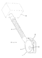
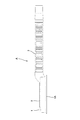
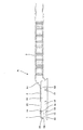
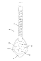
図1は本発明の一実施例にかかる集塵器具の全体の外観形状(外観構成)を示す斜視図、図2は図1に示す集塵器具の構成を示す平面図、図3は同側面図、図7は図2のVII −VII 矢視断面図である。 FIG. 1 is a perspective view showing the overall external shape (external configuration) of a dust collecting apparatus according to one embodiment of the present invention, FIG. 2 is a plan view showing the configuration of the dust collecting apparatus shown in FIG. 1, and FIG. 7 and 7 are cross-sectional views taken along arrows VII-VII in FIG.
図1において、Aは穿設工具用集塵器具で、この集塵器具Aは、箱体本体部分1と、該箱体本体部分1と別体になった平面視が円形状の蓋部材2と、箱体本体部分1に形成されている吸引口1U(図4,図7参照)に内部のホース通路が連通し該箱体本体部分1と一体になった吸引ホース3とを具備している。
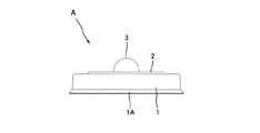
前記箱体本体部分1は、図2に図示するように、平面視において各角部がラウンド状になった全体が菱形になった、所定高さを有する箱状の形態(図1〜図3,図5,図6参照)を有し、図4,図7に図示するように、この箱本体部分1の下面1Cが全面にわたって開口している。そして、前記下面1Cの周縁には外方へ延びるように、且つ外方へゆくに従って薄くになった薄膜状の可撓性の高い当接部材1Aが一体に形成され、被加工物の加工面との間でシールできるよう構成されている。
また、図4あるいは図7等に図示するように、この箱体本体部分1の上面の一つの角部分(菱形の90度より夾角になった後部の上面の角部分)に前記吸引口1Uが形成されている。この吸引口1Uが形成されている角部は、図2図4に図示するように、平面視において他の角部に比べて大きな曲率半径でもってラウンド状に形成されている。そして、図4,図7に図示するように、前記吸引口1Uから、前記吸引ホース3の内部が該吸引口1Uに連通するように、該吸引ホース3が一端に延設されている。そして、この吸引ホース3の基端は、吸引装置(集塵機)Bの吸引口側に接続されており、該吸引ホース3から吸引口1Uを介して前記箱本体部分1の内部を負圧にすることができるように構成されている。
In FIG. 1, A is a dust collecting tool for a drilling tool, and this dust collecting tool A includes a
As shown in FIG. 2, the
Further, as shown in FIG. 4 or FIG. 7 and the like, the
また、図2,図4に図示するように、前記箱体本体部分1の吸引口1Uが形成されている対角の角部も、90度より夾角になった角部となっている。この実施例の場合、この夾角になった角部は、略75度程度に形成されているが、この角度に限定されるものでなく、90度より夾角になっておればよく、例えば、60度〜85度であってもよい。
また、前記箱体本体部分1の上面には、前記蓋部材2が挿着される平面視円形状の開口穴1Hが形成されるとともに、図4,図7に図示するように、前記蓋部材2の底面側には突起状になった鍔部2aがリング状に形成されており、このリング状の鍔部2aの外周寸法(外径)は前記開口穴1Hとほぼ等しい(正確には僅かに大きい)寸法に形成されている。また、これら箱体本体部分1および蓋部材2は共に硬質ゴム(あるいは軟質プラスティック)で構成されている。このため、前記蓋部材2に少し力を込めて前記箱体本体部分1の開口穴1Hに挿着すると、図1,図2あるいは図4等に図示するように、箱体本体部分1の開口穴1Hに蓋部材2が嵌合した状態で一体状になるよう取着されるよう構成されている。
また、前記蓋部材2は、この実施例の場合、箱体本体部分1内に収容されているドリルの様子が視認できるようにするために、全体がほぼ透明状の材質で構成されている。しかし、内部が僅かに透けて見える半透明状の材質で構成してもよい。なお、前記箱体本体1全体あるいはその一部を透明あるいは半透明の材質で構成しても、同様に箱体本体部分1内に収容されているドリルの様子が視認できる構成が実現できる。
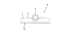
また、図1,図2,図8等に図示するように、平面視において円形状をしている前記蓋部材2の該円形状の中心から偏芯した部位に中心が位置するように、ドリルの先端を前記箱本体部分1の下面に向けて挿通する平面視において円形状の開口部2Cが形成されている。従って、前記箱体本体1部分に対して前記蓋部材2を相対的に回転させると、図8に実線と二点鎖線で図示するように、箱体本体部分1に対して前記開口部2Cの位置が相対的に変化できるように構成されている。
この実施例の場合、図4,図7に図示するように、前記箱体本体部分1の開口穴1Hの外周方には、この開口穴1Hの外周縁に隣接してサークル状(リング状)の隔壁1Wが上面から下端まで形成されており、前記箱体本体部分1の吸引口1Cが位置する空間1Sと前記開口部2Cが位置する空間(開口穴1Hが位置する空間)1Vとを区画するように構成されている。前記隔壁1Wは、具体的には図示しないが、別の実施例としては、蓋部材2の外周縁に隣接するようにその内方部分の蓋部材2側にサークル状(リング状)に形成することによって、前記箱体本体部分1の吸引口1Cが位置する空間1Sと前記開口部2Cが位置する空間(開口穴1Hが位置する空間)1Vとを区画するように構成してもよい。
そして、この隔壁1Wの下端面(底面側の端面)には、図4,図7に図示するように、開口穴1Hの内方へ向けて延びるように、且つ内方へゆくに従って薄くになった薄膜状の可撓性の高い当接部材1Rが一体に形成されて、前記開口部2C(前記開口穴1H)が位置する空間1Vと被加工物の加工面との間をシールできるよう構成されている。
また、前記隔壁1Wには、複数箇所に、この実施例では4箇所に、連通穴1Tが形成されている。この実施例の場合、前記連通穴1Tは、前記吸引口1Uの前方から両側に離間した位置に2箇所と、前記吸引ホース3の長手方向に略直交する方向に平行で且つ前記開口穴1Hの直径方向へ延びた位置に2箇所の合計4箇所に形成されている。しかし、この連通穴1Tは、4箇所に限定されるものでなく、6箇所あるいはそれ以上であってもよく、また位置についても、適宜選択的に設けることができる。しかし、前記吸引口1Uの真正面あるいはそれに近い位置に設けることは、その位置に配置された連通穴1Tからの吸引量が増加し、この隔壁1Wと箱体本体部分1の外周壁および上面で囲われた空間1Sの負圧を安定して維持する上で、好ましくない。
As shown in FIGS. 2 and 4, the diagonal corner portion where the
In addition, an
In the case of this embodiment, the
In addition, as shown in FIGS. 1, 2, 8, etc., the drill is so positioned that the center is located in a portion eccentric from the center of the circular shape of the
In the case of this embodiment, as shown in FIGS. 4 and 7, the outer peripheral side of the
The lower end surface (end surface on the bottom surface side) of the
The
ところで、この実施例では、前記吸引ホース3は、蛇腹状のもので構成されており、従って小さな屈曲半径でもって簡単に屈曲させることが可能となっている。また、材質的にも、前記箱体本体部分1と同じ硬質ゴム(あるいは軟質プラスチック)から構成されているため、小さな屈曲半径でもって屈曲させることが可能となっている。
By the way, in this embodiment, the
そして、好ましい実施例としては、前記蓋部材2は、前記開口部2Cの穴径毎に、あるいは所定の穴径範囲毎に、複数個用意しておくことが、開口部2Cとドリルの外周壁との間の隙間(空隙)を必要最小限に保つことができる点で好ましい構成となる。
As a preferred embodiment, a plurality of the
しかして、このように構成された本集塵器具Aの場合、以下のような作用効果を奏することができる。つまり、穿設しようとする被加工物の加工面上に、前記穿設工具用集塵器具Aを、前記当接部材1Aおよび当接部材1Rが該加工面と接触するような状態で、且つ、前記開口部2Cが穿設しようとする位置に略位置するような状態で配置する。もちろん、このように穿設作業をおこなう際には、この集塵器具Aの吸引ホース3の基端は、吸引装置側に接続されている。また、前記蓋部材2が開口部2の穴径毎に複数用意されている場合には、穿設しようとするドリルの外径に合致した蓋部材2を箱体本体部分1に予め取着しておく。
そして、この集塵器具Aの前記開口部2Cから、ドリルの先端が加工面に当接するように該ドリルを挿通するが、かかる際に蓋部材2がほぼ透明の材質で構成されていることから、この蓋部材2の外方(上方)からドリルが穿設しようとする穴位置と一致しているか否か視認することができる。
Therefore, in the case of the present dust collector A configured as described above, the following operational effects can be achieved. In other words, the dust collection tool A for the drilling tool is placed on the processing surface of the workpiece to be drilled so that the
Then, the drill is inserted through the
また、この集塵器具Aの場合、平面視において端部が接触するよう立設されている二つの壁面に挟まれた床面等の加工面上に穿設作業をしようとするときにも、この集塵器具Aの両側面あるいは一方の側面を該壁面に当接させた状態において、蓋部材2を箱体本体部分1に対して相対的に回転させることによって、前記開口部2Cの位置を変えることによって、穿設しようとする穴の位置とドリルの先端の位置とを一致させることが可能となる。
また、箱体本体部分1が平面視において先端が90度より夾角になった菱形の形状に構成されているため、前記二つの壁面の挟み角が90度より小さい場合にも、あるいは一方の壁面から何かが他方の壁面側に突設しているような場合にも、この集塵器具Aをこれら二つの壁の間に配置することが可能となる。つまり、二つの壁面で形成される角に近い位置からより離間した位置まで、所定範囲において穿設することができ、当該所定範囲において角部を形成する両側の壁面(あるいは一方の壁面)に箱体本体部分1の側面を当接させて位置決めすることができる。
Further, in the case of this dust collecting device A, when trying to perform a drilling operation on a processing surface such as a floor surface sandwiched between two wall surfaces that are erected so that the end portion comes into contact in a plan view, In a state where both side surfaces or one side surface of the dust collecting device A is in contact with the wall surface, the position of the opening 2C is adjusted by rotating the
In addition, since the
そして、このように、ドリルの位置を穿設しようとする穴位置に合わせた状態で、前記吸引装置をONにして、回転工具(例えば、電動ドリルあるいは空圧ドリル)を回転させると、ドリルが加工面において穿設をおこない、かかる穿設作業において発生する切り屑等の塵芥は、前記開口部2Cが位置する空間1Vから前記連通穴1Tを経て、前記空間1Sに、さらに、この空間1Sに連通する前記吸引口1Uから吸引ホース3側に吸引される。かかる集塵の際に、前述のように、隔壁1Wによって、箱体本体部分1の外周壁の内部の空間1Sが開口部2Cが設けれている空間1Vと隔壁されることによって、前記空間1Sが、穿設作業中、ほぼ所定の負圧状態に安定して維持されるため、安定した集塵機能を発揮することが可能となっている。
また、前述のように吸引ホース3が、吸引口1Uを有する箱体本体部分1と一体に形成されているため、また吸引ホース3が蛇腹状に構成されているため、さらには前述のように硬質ゴムあるいは軟質プラスチックの材料によって構成されているため、狭い空間で穿設作業等おこなう際も、吸引ホース3を小さな曲率半径で屈曲させることができる。
In this way, when the position of the drill is matched with the hole position to be drilled, the suction device is turned on and a rotary tool (for example, an electric drill or a pneumatic drill) is rotated. Drilling is performed on the machining surface, and dust such as chips generated in the drilling operation passes from the
Moreover, since the
また、別の実施例として、前記箱体本体部分1および蓋部材2および吸引ホース3の全てを透明あるいは半透明の部材によって構成してもよく、かかる場合には、ドリルの位置合わせ、および穿設状態と集塵の状況が視認できる点でさらに好ましい実施例となる。
As another example, all of the
また、この発明にかかる穿設工具用集塵器具は、所謂乾式の他に切削液(切削水)を用いる湿式においても用いることができ、湿式の場合には、殆どの水分も塵芥と一緒に吸引装置側に回収することが可能となる。 Moreover, the dust collecting tool for a drilling tool according to the present invention can be used not only in a so-called dry type but also in a wet type in which a cutting fluid (cutting water) is used. It can be collected on the suction device side.
本願発明にかかるは穿設工具用集塵器具は、金属、石材、セメント、木材、複合材料等の被加工物に穴明け作業の際の集塵装置として用いることができる。 The dust collector for a drilling tool according to the present invention can be used as a dust collector for drilling a workpiece such as metal, stone, cement, wood, or composite material.
A…集塵器具
1…箱本体部分
1A…当接部材
1C…下面
1T…連通穴 1U…吸引口
1W…隔壁
2…蓋部材
2C…開口部
3…吸引ホース
A ... Dust collector
1 ... Box body
1A: Contact member
1C ... Bottom
1T ...
1W ... Bulkhead
2 ... Lid member
2C ... opening
3 ... Suction hose
Claims (6)
前記箱体が、前記開口部とその周部からなる蓋部材と、箱体本体部分からなり、
この蓋部材が箱体本体部分に対して回転可能に配置されるとともに、
前記開口部が箱体本体部分に対して前記回転する際の中心から偏芯した位置に形成されていることを特徴とする集塵器具。 An opening through which a drill is inserted is formed on the upper surface of the box having an open bottom surface, and a suction port for connecting the base end to the tip of a suction hose connected to the suction device and making the inside of the box negative pressure A dust collecting tool for a drilling tool formed in the box and having a highly flexible contact member around the lower surface of the box,
The box body is composed of a lid member composed of the opening and the peripheral portion thereof, and a box body portion.
While this lid member is rotatably arranged with respect to the box body part,
The dust collector according to claim 1, wherein the opening is formed at a position eccentric from a center when the opening rotates with respect to the box body.
The partition is formed in a circle shape in a plan view, and the partition is formed so as to be positioned on the outer periphery of the periphery of the lid member in a state where the lid member is attached to the box body portion. The dust collecting apparatus according to claim 5, wherein:
Priority Applications (15)
| Application Number | Priority Date | Filing Date | Title |
|---|---|---|---|
| JP2005005485A JP2006192525A (en) | 2005-01-12 | 2005-01-12 | Dust collector for drilling tool |
| CNB2005800464240A CN100519018C (en) | 2005-01-12 | 2005-12-28 | Dust collector for hole-boring tool |
| ES05844856T ES2343893T3 (en) | 2005-01-12 | 2005-12-28 | POWDER COLLECTOR TOOL TO DRILL HOLES. |
| PCT/JP2005/024114 WO2006075529A1 (en) | 2005-01-12 | 2005-12-28 | Dust collector for hole-boring tool |
| RU2007130715/02A RU2356701C1 (en) | 2005-01-12 | 2005-12-28 | Dust catcher used in drilling of objects |
| AT05844856T ATE468192T1 (en) | 2005-01-12 | 2005-12-28 | DUST COLLECTOR FOR DRILLING TOOLS |
| AU2005325094A AU2005325094B9 (en) | 2005-01-12 | 2005-12-28 | Dust collector for hole-boring tool |
| US11/813,749 US8113747B2 (en) | 2005-01-12 | 2005-12-28 | Drill dust collector |
| DE602005021404T DE602005021404D1 (en) | 2005-01-12 | 2005-12-28 | DUST RECIPROCATOR FOR DRILLING TOOL |
| CA2594126A CA2594126C (en) | 2005-01-12 | 2005-12-28 | Drill dust collector |
| EP05844856A EP1894653B1 (en) | 2005-01-12 | 2005-12-28 | Dust collector for hole-boring tool |
| KR1020077007695A KR101199673B1 (en) | 2005-01-12 | 2005-12-28 | Dust collector for hole-boring tool |
| UAA200709174A UA88349C2 (en) | 2005-01-12 | 2005-12-28 | dust collector for hole-boring tool |
| BRPI0517187-3A BRPI0517187A (en) | 2005-01-12 | 2005-12-28 | drill dust collector |
| HK08101602.0A HK1107793A1 (en) | 2005-01-12 | 2008-02-14 | Dust collector for hole-boring tool |
Applications Claiming Priority (1)
| Application Number | Priority Date | Filing Date | Title |
|---|---|---|---|
| JP2005005485A JP2006192525A (en) | 2005-01-12 | 2005-01-12 | Dust collector for drilling tool |
Related Child Applications (1)
| Application Number | Title | Priority Date | Filing Date |
|---|---|---|---|
| JP2011002205U Continuation JP3168863U (en) | 2011-04-20 | 2011-04-20 | Dust collector for drilling tools |
Publications (1)
| Publication Number | Publication Date |
|---|---|
| JP2006192525A true JP2006192525A (en) | 2006-07-27 |
Family
ID=36677557
Family Applications (1)
| Application Number | Title | Priority Date | Filing Date |
|---|---|---|---|
| JP2005005485A Pending JP2006192525A (en) | 2005-01-12 | 2005-01-12 | Dust collector for drilling tool |
Country Status (15)
| Country | Link |
|---|---|
| US (1) | US8113747B2 (en) |
| EP (1) | EP1894653B1 (en) |
| JP (1) | JP2006192525A (en) |
| KR (1) | KR101199673B1 (en) |
| CN (1) | CN100519018C (en) |
| AT (1) | ATE468192T1 (en) |
| AU (1) | AU2005325094B9 (en) |
| BR (1) | BRPI0517187A (en) |
| CA (1) | CA2594126C (en) |
| DE (1) | DE602005021404D1 (en) |
| ES (1) | ES2343893T3 (en) |
| HK (1) | HK1107793A1 (en) |
| RU (1) | RU2356701C1 (en) |
| UA (1) | UA88349C2 (en) |
| WO (1) | WO2006075529A1 (en) |
Cited By (5)
| Publication number | Priority date | Publication date | Assignee | Title |
|---|---|---|---|---|
| JP2008132586A (en) * | 2006-10-25 | 2008-06-12 | Kotogawa:Kk | Cleaning device and refuse removing method |
| JP2009029095A (en) * | 2007-07-26 | 2009-02-12 | Diatecnica:Kk | Dual cylinder vacuum water suction processing pad |
| JP2010155293A (en) * | 2008-12-26 | 2010-07-15 | Lobtex Co Ltd | Scattering preventive cover |
| JP2011036971A (en) * | 2009-08-17 | 2011-02-24 | Horicon Co Ltd | Guide attachment of electric drill and boring machine including the same |
| CN105690576A (en) * | 2015-01-15 | 2016-06-22 | 江苏师范大学 | Wall surface drilling machine |
Families Citing this family (34)
| Publication number | Priority date | Publication date | Assignee | Title |
|---|---|---|---|---|
| JP4802070B2 (en) * | 2006-09-12 | 2011-10-26 | 株式会社ミヤナガ | Dust collector for drilling tools |
| GB2449463A (en) * | 2007-05-23 | 2008-11-26 | Alan Eric Gillett | Accessory tool for a vacuum cleaner |
| US9562921B2 (en) | 2008-03-25 | 2017-02-07 | Ortho-Clinical Diagnostics, Inc. | Immunodiagnostic test element having weakened foil layer |
| DE202008008561U1 (en) * | 2008-06-19 | 2008-09-04 | Electrostar Schöttle GmbH & Co. KG | Apparatus for extracting cuttings during drilling by means of a drill in masonry and the like. |
| IT1393507B1 (en) * | 2009-03-26 | 2012-04-27 | Ratta | ASPIRATOR DEVICE TO BE USED WITH A DRILL THAT ALLOWS TO ELIMINATE THE POWDERS PRODUCED DURING DRILLING. |
| GB0910899D0 (en) * | 2009-06-24 | 2009-08-05 | Airbus Operations Ltd | Contaminant extraction apparatus |
| JP5575429B2 (en) * | 2009-07-10 | 2014-08-20 | 株式会社マキタ | Dust collection attachment |
| US8757937B1 (en) * | 2009-09-17 | 2014-06-24 | The Boeing Company | Drill template tool with integral seal |
| GB0921860D0 (en) * | 2009-12-15 | 2010-01-27 | Black & Decker Inc | Dust extractor |
| GB0921855D0 (en) * | 2009-12-15 | 2010-01-27 | Black & Decker Inc | Dust extractor |
| GB0921856D0 (en) * | 2009-12-15 | 2010-01-27 | Black & Decker Inc | Dust extractor |
| GB0921861D0 (en) | 2009-12-15 | 2010-01-27 | Black & Decker Inc | Dust extractor |
| JP2011189484A (en) * | 2010-03-16 | 2011-09-29 | Makita Corp | Dust collector and power tool with dust collector |
| JP5425708B2 (en) * | 2010-05-26 | 2014-02-26 | 株式会社マキタ | Impact tool |
| JP2012016790A (en) * | 2010-07-08 | 2012-01-26 | Makita Corp | Dust collection device |
| US8529170B2 (en) | 2010-08-25 | 2013-09-10 | Ernest Everington, JR. | Retractable drill mounted dust collector |
| GB2487062A (en) * | 2011-01-06 | 2012-07-11 | Black & Decker Inc | Dust extractor with air passages |
| GB2487063A (en) * | 2011-01-06 | 2012-07-11 | Black & Decker Inc | Suction cup dust extractor with inner and outer walls |
| DE202011050242U1 (en) * | 2011-05-24 | 2011-06-28 | SSB Fidan GmbH, 86415 | Slurry collector |
| US9221142B2 (en) | 2013-03-14 | 2015-12-29 | Orbital Atk, Inc. | Guard assembly |
| US9833886B1 (en) * | 2013-03-28 | 2017-12-05 | The Boeing Company | Fastener retrieval system |
| USD741557S1 (en) | 2014-01-15 | 2015-10-20 | Milwaukee Electric Tool Corporation | Dust collector |
| USD742081S1 (en) | 2014-01-15 | 2015-10-27 | Milwaukee Electric Tool Corporation | Dust collector |
| US10238252B2 (en) | 2014-05-15 | 2019-03-26 | Christopher Joseph Buczek | Dust collector for a drill press or system |
| DE102014008232A1 (en) * | 2014-06-11 | 2015-12-17 | Airbus Operations Gmbh | Suction device and method for processing a component |
| AT516022B1 (en) * | 2014-10-01 | 2016-02-15 | Guzmics Bernd | Accessories for hand drills with integrated Bohrstaubabsaugung |
| US10391565B2 (en) * | 2017-02-17 | 2019-08-27 | Alain Gary Mazer | Hole saw guide |
| RU188682U1 (en) * | 2018-09-25 | 2019-04-22 | Вилорий Хайдарович Кашапов | DUST COLLECTOR FOR DUST COLLECTION WHEN DRILLING HOLES |
| GB201909531D0 (en) | 2019-07-02 | 2019-08-14 | Black & Decker Inc | Collar system for a dust extractor |
| CH716558A1 (en) * | 2019-09-04 | 2021-03-15 | Ssb Fidan Gmbh | Extraction device for the collected removal of cooling water when drilling wet holes on a first building wall. |
| GB2600081A (en) * | 2020-09-08 | 2022-04-27 | Plumbingenuity Ltd | Support device |
| CN113775305A (en) * | 2021-09-30 | 2021-12-10 | 卢强 | Coal mine gas extraction drilling dust falling device and using method thereof |
| KR20230171772A (en) | 2022-06-14 | 2023-12-21 | 김정선 | Dust collecting apparatus for punching drill |
| DE102022127135A1 (en) | 2022-10-17 | 2024-04-18 | Wolfcraft Gmbh | Extraction device |
Citations (8)
| Publication number | Priority date | Publication date | Assignee | Title |
|---|---|---|---|---|
| JPS5815830A (en) * | 1981-07-17 | 1983-01-29 | 池田 晃郎 | Dust collector |
| US4662802A (en) * | 1984-05-17 | 1987-05-05 | Oesterman Bror Erik | Device for effecting a seal against an underlying surface |
| JPS62215774A (en) * | 1986-03-17 | 1987-09-22 | 小林 直彦 | Drilling construction method for injection of chemical agen for repairing building |
| GB2262159A (en) * | 1991-12-06 | 1993-06-09 | Kontor Moulding Systems Ltd | Thrust-applying drill hood |
| WO1994025219A1 (en) * | 1993-04-26 | 1994-11-10 | Peter Noble | Drill dust collecting device |
| JPH09271621A (en) * | 1996-04-02 | 1997-10-21 | Rentaruno Nikken:Kk | Dust collection instrument of construction site |
| WO1999044786A1 (en) * | 1998-03-04 | 1999-09-10 | Alouette Innovation Limited | Dust collection device |
| JP2005138270A (en) * | 2003-11-10 | 2005-06-02 | Tsuneo Sato | Powder dust suction tool for electric drill |
Family Cites Families (17)
| Publication number | Priority date | Publication date | Assignee | Title |
|---|---|---|---|---|
| US2145939A (en) * | 1936-09-24 | 1939-02-07 | James H Markley | Dust hood |
| JPS59124010A (en) | 1982-12-29 | 1984-07-18 | Sony Corp | Recording method of pcm signal |
| NL8801466A (en) * | 1988-06-07 | 1990-01-02 | Emerson Electric Co | DEVICE FOR DRIVING A DRILL AND / OR IMPACT TOOL. |
| GB9408403D0 (en) * | 1994-04-28 | 1994-06-22 | Hodgson Philip | Dust extractor |
| DE19543599B4 (en) | 1995-11-23 | 2007-01-25 | Vorwerk & Co. Interholding Gmbh | Extraction device for drilling dust resulting from drilling |
| WO1997025182A1 (en) | 1996-01-04 | 1997-07-17 | British Aerospace Public Limited Company | Debris removal |
| US5807034A (en) * | 1996-07-19 | 1998-09-15 | Mcdonnell Douglas Corporation | Vacuum drill plate |
| FR2770991B1 (en) * | 1997-11-17 | 1999-12-31 | Patrick Thevenin | DRILLING DUST VACUUM NOZZLE |
| DE19951479B4 (en) * | 1998-11-16 | 2008-03-20 | Steffgen, Helga | Suction device for a tool |
| GB0021127D0 (en) * | 2000-08-30 | 2000-10-11 | Mcpartun Brian | Dust collection device |
| RU22358U1 (en) | 2001-10-26 | 2002-03-27 | Кузнецов Андрей Леонидович | DEVICE FOR REMOVING DRILLING PRODUCTS |
| US20030170082A1 (en) * | 2002-03-08 | 2003-09-11 | The Boeing Company | Multiple-port drill plate and method for debris containment |
| US20050000052A1 (en) * | 2003-07-03 | 2005-01-06 | Byles Raymond G. | Vacuum attachment for drilling tool |
| DE202006009078U1 (en) * | 2006-06-09 | 2007-10-25 | Wolfcraft Gmbh | Drilling or milling edge with chip removal device |
| US8529169B2 (en) * | 2007-12-07 | 2013-09-10 | Hitachi Koki Co., Ltd. | Drilling tool with dust collector |
| US20090181606A1 (en) * | 2008-01-15 | 2009-07-16 | Michael Loveless | Vacuum shroud for use with drilling tools |
| DE202008008561U1 (en) * | 2008-06-19 | 2008-09-04 | Electrostar Schöttle GmbH & Co. KG | Apparatus for extracting cuttings during drilling by means of a drill in masonry and the like. |
-
2005
- 2005-01-12 JP JP2005005485A patent/JP2006192525A/en active Pending
- 2005-12-28 AT AT05844856T patent/ATE468192T1/en active
- 2005-12-28 BR BRPI0517187-3A patent/BRPI0517187A/en not_active IP Right Cessation
- 2005-12-28 CA CA2594126A patent/CA2594126C/en not_active Expired - Fee Related
- 2005-12-28 US US11/813,749 patent/US8113747B2/en active Active
- 2005-12-28 WO PCT/JP2005/024114 patent/WO2006075529A1/en active Application Filing
- 2005-12-28 RU RU2007130715/02A patent/RU2356701C1/en not_active IP Right Cessation
- 2005-12-28 DE DE602005021404T patent/DE602005021404D1/en active Active
- 2005-12-28 CN CNB2005800464240A patent/CN100519018C/en active Active
- 2005-12-28 UA UAA200709174A patent/UA88349C2/en unknown
- 2005-12-28 KR KR1020077007695A patent/KR101199673B1/en active IP Right Grant
- 2005-12-28 EP EP05844856A patent/EP1894653B1/en active Active
- 2005-12-28 ES ES05844856T patent/ES2343893T3/en active Active
- 2005-12-28 AU AU2005325094A patent/AU2005325094B9/en active Active
-
2008
- 2008-02-14 HK HK08101602.0A patent/HK1107793A1/en not_active IP Right Cessation
Patent Citations (8)
| Publication number | Priority date | Publication date | Assignee | Title |
|---|---|---|---|---|
| JPS5815830A (en) * | 1981-07-17 | 1983-01-29 | 池田 晃郎 | Dust collector |
| US4662802A (en) * | 1984-05-17 | 1987-05-05 | Oesterman Bror Erik | Device for effecting a seal against an underlying surface |
| JPS62215774A (en) * | 1986-03-17 | 1987-09-22 | 小林 直彦 | Drilling construction method for injection of chemical agen for repairing building |
| GB2262159A (en) * | 1991-12-06 | 1993-06-09 | Kontor Moulding Systems Ltd | Thrust-applying drill hood |
| WO1994025219A1 (en) * | 1993-04-26 | 1994-11-10 | Peter Noble | Drill dust collecting device |
| JPH09271621A (en) * | 1996-04-02 | 1997-10-21 | Rentaruno Nikken:Kk | Dust collection instrument of construction site |
| WO1999044786A1 (en) * | 1998-03-04 | 1999-09-10 | Alouette Innovation Limited | Dust collection device |
| JP2005138270A (en) * | 2003-11-10 | 2005-06-02 | Tsuneo Sato | Powder dust suction tool for electric drill |
Cited By (5)
| Publication number | Priority date | Publication date | Assignee | Title |
|---|---|---|---|---|
| JP2008132586A (en) * | 2006-10-25 | 2008-06-12 | Kotogawa:Kk | Cleaning device and refuse removing method |
| JP2009029095A (en) * | 2007-07-26 | 2009-02-12 | Diatecnica:Kk | Dual cylinder vacuum water suction processing pad |
| JP2010155293A (en) * | 2008-12-26 | 2010-07-15 | Lobtex Co Ltd | Scattering preventive cover |
| JP2011036971A (en) * | 2009-08-17 | 2011-02-24 | Horicon Co Ltd | Guide attachment of electric drill and boring machine including the same |
| CN105690576A (en) * | 2015-01-15 | 2016-06-22 | 江苏师范大学 | Wall surface drilling machine |
Also Published As
| Publication number | Publication date |
|---|---|
| BRPI0517187A (en) | 2008-09-30 |
| ES2343893T3 (en) | 2010-08-12 |
| UA88349C2 (en) | 2009-10-12 |
| AU2005325094A1 (en) | 2006-07-20 |
| EP1894653A4 (en) | 2008-10-08 |
| EP1894653B1 (en) | 2010-05-19 |
| HK1107793A1 (en) | 2008-04-18 |
| KR101199673B1 (en) | 2012-11-08 |
| KR20070100227A (en) | 2007-10-10 |
| RU2007130715A (en) | 2009-02-20 |
| CA2594126C (en) | 2010-04-20 |
| AU2005325094B9 (en) | 2009-10-22 |
| ATE468192T1 (en) | 2010-06-15 |
| EP1894653A1 (en) | 2008-03-05 |
| WO2006075529A1 (en) | 2006-07-20 |
| CN100519018C (en) | 2009-07-29 |
| AU2005325094B2 (en) | 2009-08-06 |
| DE602005021404D1 (en) | 2010-07-01 |
| CN101098766A (en) | 2008-01-02 |
| RU2356701C1 (en) | 2009-05-27 |
| US8113747B2 (en) | 2012-02-14 |
| US20090172911A1 (en) | 2009-07-09 |
| CA2594126A1 (en) | 2006-07-20 |
Similar Documents
| Publication | Publication Date | Title |
|---|---|---|
| JP2006192525A (en) | Dust collector for drilling tool | |
| JP4802070B2 (en) | Dust collector for drilling tools | |
| JP3168863U (en) | Dust collector for drilling tools | |
| WO2018052118A1 (en) | Core drill | |
| KR100531204B1 (en) | Dust protector of hammer drill | |
| JPS6240781Y2 (en) | ||
| CN112638610B (en) | Extraction device for core drilling machine | |
| JP2006334301A (en) | Suction tool for vacuum cleaner | |
| JP5376397B2 (en) | Protective cover and power tool with protective cover | |
| JP4463250B2 (en) | Vacuum cleaner | |
| JP3120050U (en) | Chip receiving cover | |
| JP4203366B2 (en) | Electric tool with dust cover | |
| CN110815590B (en) | Corner drilling machine | |
| JPH0110170Y2 (en) | ||
| JP4552602B2 (en) | Cutting tools | |
| USD505305S1 (en) | Wall paper corner tool | |
| JPS6128418A (en) | Suction port of dust sucking apparatus | |
| JPH10329134A (en) | Dust collecting shank of dust collection type drill and its production | |
| JPH09248786A (en) | Dust collecting case of single shaft robot | |
| JPS5831657Y2 (en) | Compressed air tool with rotating joint | |
| JP2008162007A (en) | Enclosure apparatus | |
| JPS62130112A (en) | Perforating tool | |
| JP2008018525A (en) | Powder dust collecting device of portable boring machine | |
| JPH10277812A (en) | Lathe turning cutting tool with chip discharge mechanism | |
| JP2004322278A (en) | Cutting apparatus |
Legal Events
| Date | Code | Title | Description |
|---|---|---|---|
| A621 | Written request for application examination |
Free format text: JAPANESE INTERMEDIATE CODE: A621 Effective date: 20071205 |
|
| A131 | Notification of reasons for refusal |
Free format text: JAPANESE INTERMEDIATE CODE: A131 Effective date: 20101109 |
|
| A521 | Request for written amendment filed |
Free format text: JAPANESE INTERMEDIATE CODE: A523 Effective date: 20110104 |
|
| A02 | Decision of refusal |
Free format text: JAPANESE INTERMEDIATE CODE: A02 Effective date: 20110308 |