JP2006145285A - Battery residual charge detector - Google Patents
Battery residual charge detector Download PDFInfo
- Publication number
- JP2006145285A JP2006145285A JP2004333283A JP2004333283A JP2006145285A JP 2006145285 A JP2006145285 A JP 2006145285A JP 2004333283 A JP2004333283 A JP 2004333283A JP 2004333283 A JP2004333283 A JP 2004333283A JP 2006145285 A JP2006145285 A JP 2006145285A
- Authority
- JP
- Japan
- Prior art keywords
- section
- current
- voltage
- battery
- temperature
- Prior art date
- Legal status (The legal status is an assumption and is not a legal conclusion. Google has not performed a legal analysis and makes no representation as to the accuracy of the status listed.)
- Pending
Links
Images


Classifications
-
- G—PHYSICS
- G01—MEASURING; TESTING
- G01R—MEASURING ELECTRIC VARIABLES; MEASURING MAGNETIC VARIABLES
- G01R31/00—Arrangements for testing electric properties; Arrangements for locating electric faults; Arrangements for electrical testing characterised by what is being tested not provided for elsewhere
- G01R31/36—Arrangements for testing, measuring or monitoring the electrical condition of accumulators or electric batteries, e.g. capacity or state of charge [SoC]
- G01R31/382—Arrangements for monitoring battery or accumulator variables, e.g. SoC
- G01R31/3842—Arrangements for monitoring battery or accumulator variables, e.g. SoC combining voltage and current measurements
-
- G—PHYSICS
- G01—MEASURING; TESTING
- G01R—MEASURING ELECTRIC VARIABLES; MEASURING MAGNETIC VARIABLES
- G01R31/00—Arrangements for testing electric properties; Arrangements for locating electric faults; Arrangements for electrical testing characterised by what is being tested not provided for elsewhere
- G01R31/36—Arrangements for testing, measuring or monitoring the electrical condition of accumulators or electric batteries, e.g. capacity or state of charge [SoC]
- G01R31/374—Arrangements for testing, measuring or monitoring the electrical condition of accumulators or electric batteries, e.g. capacity or state of charge [SoC] with means for correcting the measurement for temperature or ageing
Landscapes
- Physics & Mathematics (AREA)
- General Physics & Mathematics (AREA)
- Secondary Cells (AREA)
- Charge And Discharge Circuits For Batteries Or The Like (AREA)
- Tests Of Electric Status Of Batteries (AREA)
Abstract
Description
本発明は、例えば、携帯電話等で使用される二次電池の残容量を検出する電池残量検出装置に関する。 The present invention relates to a remaining battery level detection device that detects the remaining capacity of a secondary battery used in, for example, a mobile phone.
携帯電話やノート型パーソナルコンピュータ等の二次電池を電源とした携帯機器には、通常、電池の残容量(以下、「電池残量」という。)を検出する電池残量検出装置が搭載されている。検出された電池残量は、例えばディスプレイ等に表示され、ユーザに電池の充電時期を知らせるために利用される。 A portable device powered by a secondary battery, such as a mobile phone or a notebook personal computer, is usually equipped with a battery remaining amount detection device that detects the remaining battery capacity (hereinafter referred to as “battery remaining amount”). Yes. The detected remaining battery level is displayed on, for example, a display, and is used to inform the user of the charging time of the battery.
従来の電池残量検出装置は、例えば電流量積算方式や電圧測定方式を用いて電池残量を検出する。電流量積算方式は、電池の使用中にその電池が負荷に供給した電流を全て積算し、その積算結果から使用した電池の容量を求め、その電池の使用容量と全容量との差から電池残量を検出する方式である。この方式は、電池残量を正確に検出することができるが、高価で、しかも電池の放電中は常に電流を積算するため、電池残量検出に使用する電力を無視できないという問題がある。 A conventional battery remaining amount detection device detects a remaining battery amount using, for example, a current amount integration method or a voltage measurement method. The current amount integration method integrates all the currents supplied to the load by the battery while the battery is in use, obtains the capacity of the used battery from the integration result, and determines the remaining battery capacity from the difference between the used capacity of the battery and the total capacity. This is a method for detecting the amount. Although this method can accurately detect the remaining battery level, it is expensive and has a problem that the electric power used for detecting the remaining battery level cannot be ignored because the current is always accumulated while the battery is being discharged.
電圧測定方式は、所定の負荷を接続した状態で電池の電圧を測定し、その電圧値から電池残量を推測する方式である。この方式は、電池残量検出が必要なときだけ検出回路を動作させればよいので、検出に使用する電力が少なくて済み、かつ安価である。しかし、電流量積算方式と比較して検出精度が低いという問題がある。 The voltage measurement method is a method in which a battery voltage is measured in a state where a predetermined load is connected, and a remaining battery capacity is estimated from the voltage value. In this method, the detection circuit only needs to be operated when it is necessary to detect the remaining battery level, so that less power is required for detection and the cost is low. However, there is a problem that the detection accuracy is low compared to the current amount integration method.
電圧測定方式は、電池残量の減少に伴って電池の電圧が低下するという特性を利用している。この電池残量と電池の電圧との関係は、電池の温度及び電池の(負荷)電流に応じて変化するため、単に測定された電池の電圧値から電池残量を推測すると、正確な電池残量を検出できない場合があった。従来の電圧測定方式を採用した電池残量検出装置には、検出精度を向上させるために、電池残量検出時の電池の温度及び電池の電流を測定して、測定された温度値、電流値及び電圧値から電池残量を推測するものがある。例えば、従来の電池残量検出装置には、電池の放電電流範囲に対応する電池電圧値を複数段階に分けて所定温度範囲毎に規定する複数のデータテーブルを有するものがある(例えば、特許文献1参照。)。この電池残量検出装置は、データ処理部と、電池の電圧値データをデータ処理部に入力する電圧入力部と、電池の放電電流値のデータをデータ処理部に入力する電流入力部と、電池の温度値のデータをデータ処理部に入力する温度入力部と、メータ部とを備える。データ処理部は、上記データテーブルを用いて放電電流値によって補正された電池の残量を示す電圧値を上記段階によって表示する信号を出力する。メータ部は、データ処理部の出力を処理すると共に、段階毎の表示を行う。 The voltage measurement method uses the characteristic that the battery voltage decreases as the remaining battery level decreases. Since the relationship between the remaining battery level and the battery voltage varies depending on the battery temperature and the battery (load) current, simply estimating the remaining battery level from the measured battery voltage value gives an accurate battery level. In some cases, the amount could not be detected. In order to improve the detection accuracy, the remaining battery level detection device adopting the conventional voltage measurement method measures the battery temperature and the battery current when the remaining battery level is detected, and the measured temperature value and current value are measured. Some of them estimate the remaining battery level from the voltage value. For example, some conventional battery remaining amount detection devices have a plurality of data tables that divide a battery voltage value corresponding to a discharge current range of a battery into a plurality of stages and define each predetermined temperature range (for example, Patent Documents). 1). The battery remaining amount detecting device includes a data processing unit, a voltage input unit that inputs battery voltage value data to the data processing unit, a current input unit that inputs battery discharge current value data to the data processing unit, a battery A temperature input unit for inputting the temperature value data to the data processing unit, and a meter unit. The data processing unit outputs a signal indicating the voltage value indicating the remaining battery level corrected by the discharge current value using the data table according to the above steps. The meter unit processes the output of the data processing unit and performs display for each stage.
また、他の従来の電池残量検出装置には、電圧センサ及び電流センサの出力から電池残量を判定する電池残量判定装置を有し、その電池残量判定装置が求めた判定値を、電池の温度を検出する温度検出装置の出力に応じて補正するものがある(例えば、特許文献2参照。)。上記電池残量判定装置は、電圧と電流の関係により決定される判定値をテーブルデータとして記憶しており、電圧センサ及び電流センサの出力により電池残量を求め、電池残量が所定値基準以上であるかどうかを判定する。この場合、電池残量判定装置は、電池近傍に配置された温度検出装置によって検出された電池の温度を用いて上記電池残量を補正する。
しかしながら、電圧測定方式を採用した従来の電池残量検出装置は、電池の電圧と電流との関係から電池残量を求めるための2次元のデータテーブルを有し、さらに、温度による補正を施すため、上記データテーブルを複数持たなくてはならなかった。よって、電圧測定方式を採用した従来の電池残量検出装置は、それらのテーブルを記憶する容量の大きいメモリが必要であった。また、電流量積算方式を採用した電池残量検出装置であっても、積算処理を行うために容量の大きいメモリが必要であった。結果として、従来の電池残量検出装置は、面積の大きなメモリが必要であり、そのため、回路面積が大きくなるという問題があった。 However, the conventional battery remaining amount detection device adopting the voltage measurement method has a two-dimensional data table for obtaining the remaining battery amount from the relationship between the voltage and current of the battery, and further performs correction by temperature. I had to have multiple data tables. Therefore, the conventional battery remaining amount detection device adopting the voltage measurement method requires a memory having a large capacity for storing those tables. Further, even with a battery remaining amount detection device that employs a current amount integration method, a memory with a large capacity is required to perform integration processing. As a result, the conventional battery remaining amount detection device requires a memory having a large area, and thus has a problem that the circuit area becomes large.
本発明は、上記の課題を解決するためになされたものであり、従来の電池残量検出装置と同等の検出精度を有する回路面積の小さい電池残量検出装置を提供することを目的とする。 The present invention has been made to solve the above-described problems, and an object of the present invention is to provide a battery remaining amount detecting device having a detection accuracy equivalent to that of a conventional battery remaining amount detecting device and having a small circuit area.
本発明の電池残量検出装置は、電池の残容量を検出する電池残量検出装置であって、前記の電池の温度を検出し、その検出した温度があらかじめ設定された温度範囲である各温度区間のいずれに含まれるかを検出する温度区間検出部と、前記の電池の電流を検出し、その検出した電流があらかじめ設定された電流範囲である各電流区間のいずれに含まれるかを検出する電流区間検出部と、前記の電池の電圧とその電池の残容量区間の関係を示す複数のテーブルを有し、前記の温度区間検出部で検出された温度区間及び前記の電流区間検出部で検出された電流区間に応じてその複数のテーブルの中から1つのテーブルを選択し、その選択したテーブルを用いて、入力された前記の電池電圧が各残容量区間のいずれに含まれるかを検出する容量区間検出部を備える。以下、この電池残量検出装置を第1の電池残量検出装置という。 The remaining battery level detection device of the present invention is a remaining battery level detection device that detects the remaining capacity of the battery, detects the temperature of the battery, and each detected temperature is in a preset temperature range. A temperature section detection unit for detecting which of the sections is included, and detecting the current of the battery, and detecting which of the current sections the detected current is included in a preset current range A current section detector, and a plurality of tables showing the relationship between the battery voltage and the remaining capacity section of the battery, the temperature section detected by the temperature section detector and the current section detector One table is selected from the plurality of tables according to the current section, and the selected table is used to detect which of the remaining battery capacity sections the input battery voltage is included in. Capacity Comprising a detection unit. Hereinafter, this remaining battery level detection device is referred to as a first remaining battery level detection device.
好ましくは、第1の電池残量検出装置は、さらに、前記の電池の充電回数を検出する充電回数検出部を備える。前記の容量区間検出部は、前記の温度区間検出部で検出された温度区間、前記の電流区間検出部で検出された電流区間、及び前記の充電回数検出部で検出された充電回数に応じて前記の複数のテーブルの中から1つのテーブルを選択する。以下、この電池残量検出装置を第2の電池残量検出装置という。 Preferably, the first battery remaining amount detection device further includes a charge number detection unit that detects the number of times the battery is charged. The capacity section detection unit is responsive to a temperature section detected by the temperature section detection section, a current section detected by the current section detection section, and a charge count detected by the charge count detection section. One table is selected from the plurality of tables. Hereinafter, this remaining battery level detection device is referred to as a second remaining battery level detection device.
好ましくは、第1の電池残量検出装置において、前記の容量区間検出部は、外部から入力された外部制御信号に応じて、その動作を開始又は停止するとともに、前記の温度区間検出部及び電流区間検出部の各動作を制御する。以下、この電池残量検出装置を第3の電池残量検出装置という。 Preferably, in the first battery level detection device, the capacity section detection unit starts or stops its operation in accordance with an external control signal input from the outside, and the temperature section detection unit and current Controls each operation of the section detection unit. Hereinafter, this remaining battery level detection device is referred to as a third remaining battery level detection device.
好ましくは、第1の電池残量検出装置において、前記の複数のテーブルは、前記の各残容量区間の上限又は下限の容量である境界容量、及びその境界容量毎に設定された電圧をそれぞれ示す。前記の容量区間検出部は、前記の複数のテーブルを有し、前記の温度区間検出部で検出された温度区間及び前記の電流区間検出部で検出された電流区間に応じて前記の複数のテーブルの中から1つのテーブルを選択し、その選択したテーブルが示す前記の境界容量毎の電圧を参照電圧として順次生成し出力する参照電圧生成部と、入力された前記の電池電圧と前記の参照電圧生成部によって出力された参照電圧とを比較して、比較する毎にその比較結果に応じた第1の制御信号を出力する電圧比較部と、前記の電圧比較部が所定の第1の制御信号を出力すると、比較されていた参照電圧に対応する前記の残容量区間を、前記の電池残量を示す残容量区間として出力する容量検出部とを備える。以下、この電池残量検出装置を第4の電池残量検出装置という。 Preferably, in the first remaining battery level detection device, the plurality of tables respectively indicate a boundary capacity that is an upper limit or a lower limit capacity of each remaining capacity section, and a voltage set for each boundary capacity. . The capacity section detection unit includes the plurality of tables, and the plurality of tables according to the temperature section detected by the temperature section detection unit and the current section detected by the current section detection unit. A reference voltage generation unit that selects one table from the above, sequentially generates and outputs the voltage for each boundary capacitance indicated by the selected table as a reference voltage, and the input battery voltage and the reference voltage A voltage comparison unit that compares the reference voltage output by the generation unit and outputs a first control signal corresponding to the comparison result each time the comparison is made, and the voltage comparison unit is a predetermined first control signal Is output, the capacity detection unit outputs the remaining capacity section corresponding to the compared reference voltage as the remaining capacity section indicating the remaining battery capacity. Hereinafter, this remaining battery level detection device is referred to as a fourth remaining battery level detection device.
好ましくは、第4の電池残量検出装置において、前記の参照電圧生成部は、前記の複数のテーブルを記憶する記憶部と、前記の温度区間検出部で検出された温度区間及び前記の電流区間検出部で検出された電流区間に応じてその複数のテーブルの中から1つのテーブルを選択する選択部と、選択された前記のテーブルが示す前記の境界容量毎の電圧を参照電圧として順次生成し出力する出力部とを備える。以下、この電池残量検出装置を第5の電池残量検出装置という。 Preferably, in the fourth battery remaining amount detection device, the reference voltage generation unit includes a storage unit that stores the plurality of tables, a temperature interval detected by the temperature interval detection unit, and the current interval. A selection unit that selects one table among the plurality of tables according to the current section detected by the detection unit, and a voltage for each boundary capacitance indicated by the selected table are sequentially generated as a reference voltage. An output unit for outputting. Hereinafter, this remaining battery level detection device is referred to as a fifth remaining battery level detection device.
好ましくは、第1、第4及び第5の電池残量検出装置において、前記の温度区間検出部は、前記の電池の温度の検出を行い、検出した温度に比例した電圧である温度電圧を生成して出力する電池温度検出部と、電池の温度と温度電圧との関係を示すテーブルを有し、そのテーブルと検出された前記の温度電圧とを用いて、前記の電池の温度があらかじめ設定された温度範囲である各温度区間のいずれに含まれるかを検出して出力する第1の区間検出部とを備える。以下、この電池残量検出装置を第6の電池残量検出装置という。 Preferably, in the first, fourth and fifth remaining battery level detection devices, the temperature section detection unit detects the temperature of the battery and generates a temperature voltage which is a voltage proportional to the detected temperature. A battery temperature detection unit that outputs the relationship between the battery temperature and the temperature voltage, and the temperature of the battery is set in advance using the table and the detected temperature voltage. A first section detection unit that detects and outputs which temperature section is included in the temperature range. Hereinafter, this remaining battery level detection device is referred to as a sixth remaining battery level detection device.
好ましくは、第6の電池残量検出装置において、前記の第1の区間検出部は、前記の各温度区間の上限又は下限の温度である境界温度、及びその境界温度毎に設定された電圧を示すテーブルを有し、そのテーブルが示す前記の境界温度毎の電圧を参照温度電圧として順次生成して出力する参照温度電圧生成部と、検出された前記の温度電圧と出力された前記の各参照温度電圧とを比較して、比較する毎にその比較結果に応じた第2の制御信号を出力する温度電圧比較部と、前記の温度電圧比較部が所定の第2の制御信号を出力すると、比較されていた参照温度電圧に対応する前記の温度区間を、前記の電池温度が含まれる温度区間として出力する温度検出部とを備える。以下、この電池残量検出装置を第7の電池残量検出装置という。 Preferably, in the sixth battery level detection device, the first section detection unit calculates a boundary temperature that is an upper limit or a lower limit temperature of each temperature section, and a voltage set for each boundary temperature. A reference temperature voltage generating unit that sequentially generates and outputs a voltage for each boundary temperature indicated by the table as a reference temperature voltage, and the detected temperature voltage and each of the references that are output. A temperature voltage comparison unit that compares the temperature voltage and outputs a second control signal corresponding to the comparison result each time the comparison is made, and when the temperature voltage comparison unit outputs a predetermined second control signal, A temperature detection unit that outputs the temperature interval corresponding to the reference temperature voltage that has been compared as a temperature interval in which the battery temperature is included. Hereinafter, this remaining battery level detection device is referred to as a seventh remaining battery level detection device.
好ましくは、第1、及び第4から第7のいずれかの電池残量検出装置において、前記の電流区間検出部は、前記の電池の出力電流の検出を行い、その検出した出力電流に比例した電圧である第1の電流電圧を生成して出力する第1の電池電流検出部と、電池の出力電流と電流電圧との関係を示したテーブルを有し、そのテーブルと検出された前記の第1の電流電圧とを用いて、前記の電池の出力電流があらかじめ設定された電流範囲である各電流区間のいずれに含まれるかを検出して出力する第2の区間検出部を備える。以下、この電池残量検出装置を第8の電池残量検出装置という。 Preferably, in any one of the first and fourth to seventh battery remaining amount detection devices, the current section detection unit detects an output current of the battery, and is proportional to the detected output current. A first battery current detection unit that generates and outputs a first current voltage that is a voltage, and a table showing a relationship between the output current of the battery and the current voltage, and the table and the detected first current And a second section detection unit that detects and outputs which one of the current sections in the preset current range is included by using one current voltage. Hereinafter, this remaining battery level detection device is referred to as an eighth remaining battery level detection device.
好ましくは、第8の電池残量検出装置において、前記の第2の区間検出部は、前記の各電流区間の上限又は下限の電流である境界電流、及びその境界電流毎に設定された電圧を示すテーブルを有し、そのテーブルが示す前記の境界電流毎の電圧を参照電流電圧として順次生成して出力する参照電流電圧生成部と、検出された前記の電流電圧と出力された前記の各参照電流電圧とを比較し、比較する毎にその比較結果に応じた第3の制御信号を出力する電流電圧比較部と、前記の電流電圧比較部が所定の第3の制御信号を出力すると、比較されていた参照電流電圧に対応する前記の電流区間を、前記の電池電流が含まれる電流区間として出力する電流検出部とを備える。以下、この電池残量検出装置を第9の電池残量検出装置という。 Preferably, in the eighth battery remaining amount detection device, the second section detection unit calculates a boundary current that is an upper limit or a lower limit current of each current section, and a voltage set for each boundary current. A reference current voltage generation unit that sequentially generates and outputs a voltage for each of the boundary currents indicated by the table as a reference current voltage, and each of the detected reference voltages output. A current / voltage comparison unit that compares the current / voltage and outputs a third control signal corresponding to the comparison result each time the comparison is made, and a comparison is made when the current / voltage comparison unit outputs a predetermined third control signal. And a current detection unit that outputs the current section corresponding to the reference current voltage that has been performed as a current section including the battery current. Hereinafter, this remaining battery level detection device is referred to as a ninth remaining battery level detection device.
好ましくは、第3の電池残量検出装置において、前記の複数のテーブルは、前記の各残容量区間の上限又は下限の容量である境界容量、及びその境界容量毎に設定された電圧をそれぞれ示す。前記の容量区間検出部は、前記の複数のテーブルを有し、前記の温度区間検出部で検出された温度区間及び前記の電流区間検出部で検出された電流区間に応じて前記の複数のテーブルの中から1つのテーブルを選択し、その選択したテーブルが示す前記の境界容量毎の電圧を参照電圧として順次生成し出力する参照電圧生成部と、入力された前記の電池電圧と前記の参照電圧生成部によって出力された参照電圧とを比較して、比較する毎にその比較結果に応じた第1の制御信号を出力する電圧比較部と、前記の電圧比較部が所定の第1の制御信号を出力すると、比較されていた参照電圧に対応する前記の残容量区間を、前記の電池残量を示す残容量区間として出力する容量検出部とを備える。前記の温度区間検出部は、前記の電池の温度の検出を行い、検出した温度に比例した電圧である温度電圧を生成して出力する電池温度検出部と、電池の温度と温度電圧との関係を示すテーブルを有し、そのテーブルと検出された前記の温度電圧とを用いて、前記の電池の温度があらかじめ設定された温度範囲である各温度区間のいずれに含まれるかを検出して出力する第1の区間検出部とを備える。前記の第1の区間検出部は、前記の各温度区間の上限又は下限の温度である境界温度、及びその境界温度毎に設定された電圧を示すテーブルを有し、そのテーブルが示す前記の境界温度毎の電圧を参照温度電圧として順次生成して出力する参照温度電圧生成部と、検出された前記の温度電圧と出力された前記の各参照温度電圧とを比較して、比較する毎にその比較結果に応じた第2の制御信号を出力する温度電圧比較部と、前記の温度電圧比較部が所定の第2の制御信号を出力すると、比較されていた参照温度電圧に対応する前記の温度区間を、前記の電池温度が含まれる温度区間として出力する温度検出部とを備える。前記の電流区間検出部は、前記の電池の出力電流の検出を行い、その検出した出力電流に比例した電圧である第1の電流電圧を生成して出力する第1の電池電流検出部と、電池の出力電流と電流電圧との関係を示したテーブルを有し、そのテーブルと検出された前記の第1の電流電圧とを用いて、前記の電池の出力電流があらかじめ設定された電流範囲である各電流区間のいずれに含まれるかを検出して出力する第2の区間検出部とを備える。前記の第2の区間検出部は、前記の各電流区間の上限又は下限の電流である境界電流、及びその境界電流毎に設定された電圧を示すテーブルを有し、そのテーブルが示す前記の境界電流毎の電圧を参照電流電圧として順次生成して出力する参照電流電圧生成部と、検出された前記の電流電圧と出力された前記の各参照電流電圧とを比較し、比較する毎にその比較結果に応じた第3の制御信号を出力する電流電圧比較部と、前記の電流電圧比較部が所定の第3の制御信号を出力すると、比較されていた参照電流電圧に対応する前記の電流区間を、前記の電池電流が含まれる電流区間として出力する電流検出部とを備える。前記の参照電圧生成部は、前記の外部制御信号に応じて、その動作を開始又は停止するとともに、前記の電圧比較部の動作を制御し、かつ前記の温度区間検出部及び電流区間検出部に、対応する第4及び第5の制御信号をそれぞれ出力する。前記の参照温度電圧生成部は、前記の参照電圧生成部から出力された前記の第4の制御信号に応じて、その動作を開始又は停止するとともに、前記の電池温度検出部及び温度電圧比較部の各動作を制御する。前記の参照電流電圧生成部は、前記の参照電圧生成部から出力された前記の第5の制御信号に応じて、その動作を開始又は停止するとともに、前記の第2の電池電流検出部及び電流電圧比較部の各動作を制御する。以下、この電池残量検出装置を、第10の電池残量検出装置という。 Preferably, in the third battery remaining amount detecting device, the plurality of tables respectively indicate a boundary capacity which is an upper limit or a lower limit capacity of each remaining capacity section and a voltage set for each boundary capacity. . The capacity section detection unit includes the plurality of tables, and the plurality of tables according to the temperature section detected by the temperature section detection unit and the current section detected by the current section detection unit. A reference voltage generation unit that selects one table from the above, sequentially generates and outputs the voltage for each boundary capacitance indicated by the selected table as a reference voltage, and the input battery voltage and the reference voltage A voltage comparison unit that compares the reference voltage output by the generation unit and outputs a first control signal corresponding to the comparison result each time the comparison is made, and the voltage comparison unit is a predetermined first control signal Is output, the capacity detection unit outputs the remaining capacity section corresponding to the compared reference voltage as the remaining capacity section indicating the remaining battery capacity. The temperature interval detection unit detects the temperature of the battery, generates a temperature voltage that is a voltage proportional to the detected temperature, and outputs the temperature voltage, and a relationship between the battery temperature and the temperature voltage And using the table and the detected temperature voltage, it detects and outputs in which temperature section the temperature of the battery is included in a preset temperature range And a first section detection unit. The first section detection unit has a table indicating a boundary temperature that is an upper limit or a lower limit temperature of each temperature section and a voltage set for each boundary temperature, and the boundary indicated by the table A reference temperature voltage generation unit that sequentially generates and outputs a voltage for each temperature as a reference temperature voltage, and compares each detected temperature voltage with each output reference temperature voltage. A temperature voltage comparison unit that outputs a second control signal according to the comparison result, and the temperature corresponding to the reference temperature voltage that has been compared when the temperature voltage comparison unit outputs a predetermined second control signal. A temperature detecting unit that outputs the section as a temperature section including the battery temperature. The current section detection unit detects the output current of the battery, generates a first current voltage that is a voltage proportional to the detected output current, and outputs the first current voltage; and It has a table showing the relationship between the output current and the current voltage of the battery, and using the table and the detected first current voltage, the output current of the battery is within a preset current range. And a second section detection unit that detects and outputs which one of the current sections is included. The second section detection unit has a table indicating a boundary current that is an upper limit or a lower limit current of each current section, and a voltage set for each boundary current, and the boundary indicated by the table A reference current voltage generator that sequentially generates and outputs a voltage for each current as a reference current voltage, and compares the detected current voltage with each of the output reference current voltages, and compares each time the comparison is performed. A current / voltage comparison unit that outputs a third control signal according to the result, and the current section corresponding to the reference current voltage that has been compared when the current / voltage comparison unit outputs a predetermined third control signal. Is provided as a current section including the battery current. The reference voltage generation unit starts or stops its operation according to the external control signal, controls the operation of the voltage comparison unit, and controls the temperature interval detection unit and the current interval detection unit. , Corresponding fourth and fifth control signals are output, respectively. The reference temperature voltage generation unit starts or stops its operation in accordance with the fourth control signal output from the reference voltage generation unit, and also includes the battery temperature detection unit and the temperature voltage comparison unit. Control each operation. The reference current voltage generation unit starts or stops its operation according to the fifth control signal output from the reference voltage generation unit, and also includes the second battery current detection unit and the current. Controls each operation of the voltage comparator. Hereinafter, this battery remaining amount detection device is referred to as a tenth battery remaining amount detection device.
好ましくは、第2の電池残量検出装置において、前記の容量区間検出部は、外部から入力された外部制御信号に応じて、その動作を開始又は停止するとともに、前記の温度区間検出部、電流区間検出部、及び充電回数検出部の各動作を制御する。以下、この電池残量検出装置を、第11の電池残量検出装置という。 Preferably, in the second battery level detection device, the capacity section detection unit starts or stops its operation in accordance with an external control signal input from the outside, and the temperature section detection unit, current Each operation | movement of a zone detection part and a charge frequency detection part is controlled. Hereinafter, this remaining battery level detection device is referred to as an 11th remaining battery level detection device.
好ましくは、第2の電池残量検出装置において、前記の複数のテーブルは、前記の各残容量区間の上限又は下限の容量である境界容量、及びその境界容量毎に設定された電圧をそれぞれ示す。前記の容量区間検出部は、前記の複数のテーブルを有し、前記の温度区間検出部で検出された温度区間、前記の電流区間検出部で検出された電流区間、及び前記の充電回数検出部で検出された充電回数に応じて前記の複数のテーブルの中から1つのテーブルを選択し、その選択したテーブルが示す前記の境界容量毎の電圧を参照電圧として順次生成し出力する参照電圧生成部と、入力された前記の電池電圧と前記の参照電圧生成部によって出力された参照電圧とを比較して、比較する毎にその比較結果に応じた第1の制御信号を出力する電圧比較部と、前記の電圧比較部が所定の第1の制御信号を出力すると、比較されていた参照電圧に対応する前記の残容量区間を、前記の電池残量を示す残容量区間として出力する容量検出部とを備える。以下、この電池残量検出装置を、第12の電池残量検出装置という。 Preferably, in the second battery remaining amount detection device, the plurality of tables respectively indicate a boundary capacity that is an upper limit or a lower limit capacity of each remaining capacity section, and a voltage set for each boundary capacity. . The capacity section detector includes the plurality of tables, the temperature section detected by the temperature section detector, the current section detected by the current section detector, and the number-of-charges detector. A reference voltage generation unit that selects one table from the plurality of tables according to the number of times of charging detected in step 1, sequentially generates and outputs a voltage for each of the boundary capacitances indicated by the selected table as a reference voltage A voltage comparison unit that compares the input battery voltage with the reference voltage output by the reference voltage generation unit and outputs a first control signal corresponding to the comparison result each time the comparison is made When the voltage comparison unit outputs a predetermined first control signal, the capacity detection unit outputs the remaining capacity section corresponding to the compared reference voltage as the remaining capacity section indicating the remaining battery capacity. With. Hereinafter, this remaining battery level detection device is referred to as a twelfth remaining battery level detection device.
好ましくは、第12の電池残量検出装置において、前記の参照電圧生成部は、前記の複数のテーブルを記憶する記憶部と、前記の温度区間検出部で検出された温度区間、前記の電流区間検出部で検出された電流区間、及び前記の充電回数検出部で検出された充電回数に応じてその複数のテーブルの中から1つのテーブルを選択する選択部と、選択された前記のテーブルが示す前記の境界容量毎の電圧を参照電圧として順次生成し出力する出力部とを備える。以下、この電池残量検出装置を、第13の電池残量検出装置という。 Preferably, in the twelfth battery remaining amount detection device, the reference voltage generation unit includes a storage unit that stores the plurality of tables, a temperature interval detected by the temperature interval detection unit, and the current interval. A selection unit that selects one table from among the plurality of tables in accordance with the current interval detected by the detection unit and the number of charging times detected by the charge number detection unit, and the selected table indicates And an output unit that sequentially generates and outputs the voltage for each boundary capacitance as a reference voltage. Hereinafter, this remaining battery level detection device is referred to as a thirteenth remaining battery level detection device.
好ましくは、第2、第12及び第13のいずれかの電池残量検出装置において、前記の温度区間検出部は、前記の電池の温度の検出を行い、検出した温度に比例した電圧である温度電圧を生成して出力する電池温度検出部と、電池の温度と温度電圧との関係を示すテーブルを有し、そのテーブルと検出された前記の温度電圧とを用いて、前記の電池の温度があらかじめ設定された温度範囲である各温度区間のいずれに含まれるかを検出して出力する第1の区間検出部とを備える。以下、この電池残量検出装置を、第14の電池残量検出装置という。 Preferably, in any one of the second, twelfth and thirteenth battery remaining amount detecting devices, the temperature section detecting unit detects the temperature of the battery and is a voltage proportional to the detected temperature. A battery temperature detection unit that generates and outputs a voltage; and a table that indicates a relationship between the temperature of the battery and the temperature voltage. Using the table and the detected temperature voltage, the temperature of the battery is determined. And a first section detection unit that detects and outputs which temperature section is included in a preset temperature range. Hereinafter, this battery remaining amount detection device is referred to as a fourteenth battery remaining amount detection device.
好ましくは、第14の電池残量検出装置において、前記の第1の区間検出部は、前記の各温度区間の上限又は下限の温度である境界温度、及びその境界温度毎に設定された電圧を示すテーブルを有し、そのテーブルが示す前記の境界温度毎の電圧を参照温度電圧として順次生成して出力する参照温度電圧生成部と、検出された前記の温度電圧と出力された前記の各参照温度電圧とを比較して、比較する毎にその比較結果に応じた第2の制御信号を出力する温度電圧比較部と、前記の温度電圧比較部が所定の第2の制御信号を出力すると、比較されていた参照温度電圧に対応する前記の温度区間を、前記の電池温度が含まれる温度区間として出力する温度検出部とを備える。以下、この電池残量検出装置を、第15の電池残量検出装置という。 Preferably, in the fourteenth battery remaining amount detection device, the first section detection unit obtains a boundary temperature that is an upper limit or a lower limit temperature of each temperature section, and a voltage set for each boundary temperature. A reference temperature voltage generating unit that sequentially generates and outputs a voltage for each boundary temperature indicated by the table as a reference temperature voltage, and the detected temperature voltage and each of the references that are output. A temperature voltage comparison unit that compares the temperature voltage and outputs a second control signal corresponding to the comparison result each time the comparison is made, and when the temperature voltage comparison unit outputs a predetermined second control signal, A temperature detection unit that outputs the temperature interval corresponding to the reference temperature voltage that has been compared as a temperature interval in which the battery temperature is included. Hereinafter, this remaining battery level detection device is referred to as a 15th remaining battery level detection device.
好ましくは、第2、及び第12から第15のいずれかの電池残量検出装置において、前記の電流区間検出部は、前記の電池の出力電流の検出を行い、その検出した出力電流に比例した電圧である第1の電流電圧を生成して出力する第1の電池電流検出部と、電池の出力電流と電流電圧との関係を示したテーブルを有し、そのテーブルと検出された前記の第1の電流電圧とを用いて、前記の電池の出力電流があらかじめ設定された電流範囲である各電流区間のいずれに含まれるかを検出して出力する第2の区間検出部とを備える。以下、この電池残量検出装置を、第16の電池残量検出装置という。 Preferably, in any one of the second and twelfth to fifteenth battery level detection devices, the current section detection unit detects an output current of the battery and is proportional to the detected output current. A first battery current detection unit that generates and outputs a first current voltage that is a voltage, and a table showing a relationship between the output current of the battery and the current voltage, and the table and the detected first current And a second section detecting unit that detects and outputs which one of the current sections that is a preset current range is included using the current voltage of the first battery. Hereinafter, this remaining battery level detection device is referred to as a sixteenth remaining battery level detection device.
好ましくは、第16の電池残量検出装置において、前記の第2の区間検出部は、前記の各電流区間の上限又は下限の電流である境界電流、及びその境界電流毎に設定された電圧を示すテーブルを有し、そのテーブルが示す前記の境界電流毎の電圧を参照電流電圧として順次生成して出力する参照電流電圧生成部と、検出された前記の電流電圧と出力された前記の各参照電流電圧とを比較し、比較する毎にその比較結果に応じた第3の制御信号を出力する電流電圧比較部と、前記の電流電圧比較部が所定の第3の制御信号を出力すると、比較されていた参照電流電圧に対応する前記の電流区間を、前記の電池電流が含まれる電流区間として出力する電流検出部とを備える。以下、この電池残量検出装置を、第17の電池残量検出装置という。 Preferably, in the sixteenth battery level detection device, the second section detection unit calculates a boundary current that is an upper limit or a lower limit current of each current section, and a voltage set for each boundary current. A reference current voltage generation unit that sequentially generates and outputs a voltage for each of the boundary currents indicated by the table as a reference current voltage, and each of the detected reference voltages output. A current / voltage comparison unit that compares the current / voltage and outputs a third control signal corresponding to the comparison result each time the comparison is made, and a comparison is made when the current / voltage comparison unit outputs a predetermined third control signal. And a current detection unit that outputs the current section corresponding to the reference current voltage that has been performed as a current section including the battery current. Hereinafter, this remaining battery level detection device is referred to as a seventeenth remaining battery level detection device.
好ましくは、第11の電池残量検出装置において、前記の複数のテーブルは、前記の各残容量区間の上限又は下限の容量である境界容量、及びその境界容量毎に設定された電圧をそれぞれ示す。前記の容量区間検出部は、前記の複数のテーブルを有し、前記の温度区間検出部で検出された温度区間、前記の電流区間検出部で検出された電流区間、及び前記の充電回数検出部で検出された充電回数に応じて前記の複数のテーブルの中から1つのテーブルを選択し、その選択したテーブルが示す前記の境界容量毎の電圧を参照電圧として順次生成し出力する参照電圧生成部と、入力された前記の電池電圧と前記の参照電圧生成部によって出力された参照電圧とを比較して、比較する毎にその比較結果に応じた第1の制御信号を出力する電圧比較部と、前記の電圧比較部が所定の第1の制御信号を出力すると、比較されていた参照電圧に対応する前記の残容量区間を、前記の電池残量を示す残容量区間として出力する容量検出部とを備える。前記の温度区間検出部は、前記の電池の温度の検出を行い、検出した温度に比例した電圧である温度電圧を生成して出力する電池温度検出部と、電池の温度と温度電圧との関係を示すテーブルを有し、そのテーブルと検出された前記の温度電圧とを用いて、前記の電池の温度があらかじめ設定された温度範囲である各温度区間のいずれに含まれるかを検出して出力する第1の区間検出部とを備える。前記の第1の区間検出部は、前記の各温度区間の上限又は下限の温度である境界温度、及びその境界温度毎に設定された電圧を示すテーブルを有し、そのテーブルが示す前記の境界温度毎の電圧を参照温度電圧として順次生成して出力する参照温度電圧生成部と、検出された前記の温度電圧と出力された前記の各参照温度電圧とを比較して、比較する毎にその比較結果に応じた第2の制御信号を出力する温度電圧比較部と、前記の温度電圧比較部が所定の第2の制御信号を出力すると、比較されていた参照温度電圧に対応する前記の温度区間を、前記の電池温度が含まれる温度区間として出力する温度検出部とを備える。前記の電流区間検出部は、前記の電池の出力電流の検出を行い、その検出した出力電流に比例した電圧である第2の電流電圧を生成して出力する第2の電池電流検出部と、電池の出力電流と電流電圧との関係を示したテーブルを有し、そのテーブルと検出された前記の第2の電流電圧とを用いて、前記の電池の出力電流があらかじめ設定された電流範囲である各電流区間のいずれに含まれるかを検出して出力する第2の区間検出部とを備える。前記の第2の区間検出部は、前記の各電流区間の上限又は下限の電流である境界電流、及びその境界電流毎に設定された電圧を示すテーブルを有し、そのテーブルが示す前記の境界電流毎の電圧を参照電流電圧として順次生成して出力する参照電流電圧生成部と、検出された前記の電流電圧と出力された前記の各参照電流電圧とを比較し、比較する毎にその比較結果に応じた第3の制御信号を出力する電流電圧比較部と、前記の電流電圧比較部が所定の第3の制御信号を出力すると、比較されていた参照電流電圧に対応する前記の電流区間を、前記の電池電流が含まれる電流区間として出力する電流検出部とを備える。前記の参照電圧生成部は、前記の外部制御信号に応じて、その動作を開始又は停止するとともに、前記の電圧比較部の動作を制御し、かつ前記の温度区間検出部、電流区間検出部、及び充電回数検出部に、それぞれ対応する第4、第5及び第6の制御信号を出力する。前記の参照温度電圧生成部は、前記の参照電圧生成部から出力された前記の第4の制御信号に応じて、その動作を開始又は停止するとともに、前記の電池温度検出部、及び温度電圧比較部の各動作を制御する。前記の参照電流電圧生成部は、前記の参照電圧生成部から出力された前記の第5の制御信号に応じて、その動作を開始又は停止するとともに、前記の第2の電池電流検出部、及び電流電圧比較部の各動作を制御する。以下、この電池残量検出装置を、第18の電池残量検出装置という。 Preferably, in the eleventh battery remaining amount detecting device, the plurality of tables respectively indicate a boundary capacity which is an upper limit or a lower limit capacity of each remaining capacity section, and a voltage set for each boundary capacity. . The capacity section detector includes the plurality of tables, the temperature section detected by the temperature section detector, the current section detected by the current section detector, and the number-of-charges detector. A reference voltage generation unit that selects one table from the plurality of tables according to the number of times of charging detected in step 1, sequentially generates and outputs a voltage for each of the boundary capacitances indicated by the selected table as a reference voltage A voltage comparison unit that compares the input battery voltage with the reference voltage output by the reference voltage generation unit and outputs a first control signal corresponding to the comparison result each time the comparison is made When the voltage comparison unit outputs a predetermined first control signal, the capacity detection unit outputs the remaining capacity section corresponding to the compared reference voltage as the remaining capacity section indicating the remaining battery capacity. With. The temperature interval detection unit detects the temperature of the battery, generates a temperature voltage that is a voltage proportional to the detected temperature, and outputs the temperature voltage, and a relationship between the battery temperature and the temperature voltage And using the table and the detected temperature voltage, it detects and outputs in which temperature section the temperature of the battery is included in a preset temperature range And a first section detection unit. The first section detection unit has a table indicating a boundary temperature that is an upper limit or a lower limit temperature of each temperature section and a voltage set for each boundary temperature, and the boundary indicated by the table A reference temperature voltage generation unit that sequentially generates and outputs a voltage for each temperature as a reference temperature voltage, and compares each detected temperature voltage with each output reference temperature voltage. A temperature voltage comparison unit that outputs a second control signal according to the comparison result, and the temperature corresponding to the reference temperature voltage that has been compared when the temperature voltage comparison unit outputs a predetermined second control signal. A temperature detecting unit that outputs the section as a temperature section including the battery temperature. The current section detection unit detects the output current of the battery, generates a second current voltage that is a voltage proportional to the detected output current, and outputs the second battery voltage detection unit; It has a table showing the relationship between the output current and the current voltage of the battery, and using the table and the detected second current voltage, the output current of the battery is within a preset current range. And a second section detection unit that detects and outputs which one of the current sections is included. The second section detection unit has a table indicating a boundary current that is an upper limit or a lower limit current of each current section, and a voltage set for each boundary current, and the boundary indicated by the table A reference current voltage generator that sequentially generates and outputs a voltage for each current as a reference current voltage, and compares the detected current voltage with each of the output reference current voltages, and compares each time the comparison is performed. A current / voltage comparison unit that outputs a third control signal according to the result, and the current section corresponding to the reference current voltage that has been compared when the current / voltage comparison unit outputs a predetermined third control signal. Is provided as a current section including the battery current. The reference voltage generation unit starts or stops its operation according to the external control signal, controls the operation of the voltage comparison unit, and the temperature interval detection unit, the current interval detection unit, And the 4th, 5th, and 6th control signal corresponding to a charge frequency detection part is output, respectively. The reference temperature voltage generation unit starts or stops its operation in accordance with the fourth control signal output from the reference voltage generation unit, and the battery temperature detection unit and the temperature voltage comparison Control each operation of the unit. The reference current voltage generation unit starts or stops its operation in accordance with the fifth control signal output from the reference voltage generation unit, and the second battery current detection unit, Control each operation of the current-voltage comparator. Hereinafter, this remaining battery level detection device is referred to as an 18th remaining battery level detection device.
好ましくは、第1、及び第4から第9のいずれかの電池残量検出装置は、さらに、前記の電池が充電中であるか又は放電中であるかを検出して、その検出結果を示す第4の制御信号を生成して出力する充放電検出部と、前記の容量区間検出部から出力された容量区間及び前記の第4の制御信号がそれぞれ入力され、前記の電池が放電を開始してから充電を開始するまでの間に、前記の容量区間検出部から出力された残容量区間のうち最も小さい容量を含む最小容量区間を保持して出力する容量保持部と、前記の容量区間検出部から出力された残容量区間と、前記の最小容量区間とを比較して、より小さい容量の区間を選択して出力する容量区間出力部とを備える。前記の容量保持部は、前記の容量区間検出部から残容量区間が出力されると、前記の電池が放電を開始してからその残容量区間が出力される前までに前記の容量区間検出部から出力された残容量区間のうち最も小さい容量を含む最小容量区間を出力する。以下、この電池残量検出装置を、第19の電池残量検出装置という。 Preferably, any one of the first and fourth to ninth battery remaining amount detection devices further detects whether the battery is being charged or discharged, and indicates the detection result. The charge / discharge detection unit that generates and outputs the fourth control signal, the capacity interval output from the capacity interval detection unit, and the fourth control signal are respectively input, and the battery starts discharging. A capacity holding unit that holds and outputs the minimum capacity section including the smallest capacity among the remaining capacity sections output from the capacity section detection unit between the start of charging and the start of charging, and the capacity section detection A remaining capacity section output from the storage section and the minimum capacity section, and a capacity section output section that selects and outputs a section having a smaller capacity. When the remaining capacity section is output from the capacity section detecting section, the capacity holding section is configured to detect the capacity section detecting section before the remaining capacity section is output after the battery starts discharging. The minimum capacity section including the smallest capacity among the remaining capacity sections output from is output. Hereinafter, this remaining battery level detection device is referred to as a nineteenth remaining battery level detection device.
好ましくは、第3又は第10の電池残量検出装置は、前記の電池が充電中であるか又は放電中であるかを検出して、その検出結果を示す第6の制御信号を生成して出力する充放電検出部と、前記の容量区間検出部から出力された容量区間及び前記の第6の制御信号がそれぞれ入力され、前記の電池が放電を開始してから充電を開始するまでの間に、前記の容量区間検出部から出力された残容量区間のうち最も小さい容量を含む最小容量区間を保持して出力する容量保持部と、前記の容量区間検出部から出力された残容量区間と、前記の最小容量区間とを比較して、より小さい容量の区間を選択して出力する容量区間出力部とを備える。前記の容量保持部は、前記の容量区間検出部から残容量区間が出力されると、前記の電池が放電を開始してからその残容量区間が出力される前までに前記の容量区間検出部から出力された残容量区間のうち最も小さい容量を含む最小容量区間を出力する。以下、この電池残量検出装置を、第20の電池残量検出装置という。 Preferably, the third or tenth battery remaining amount detection device detects whether the battery is being charged or discharged, and generates a sixth control signal indicating the detection result. The charging / discharging detection unit to be output, the capacity interval output from the capacity interval detection unit and the sixth control signal are input, and the battery starts discharging until charging starts. A capacity holding unit for holding and outputting a minimum capacity section including the smallest capacity among the remaining capacity sections output from the capacity section detecting unit, and a remaining capacity section output from the capacity section detecting unit, And a capacity section output unit that compares the minimum capacity section and selects and outputs a section having a smaller capacity. When the remaining capacity section is output from the capacity section detecting section, the capacity holding section is configured to detect the capacity section detecting section before the remaining capacity section is output after the battery starts discharging. The minimum capacity section including the smallest capacity among the remaining capacity sections output from is output. Hereinafter, this remaining battery level detection device is referred to as a twentieth remaining battery level detection device.
好ましくは、第20の電池残量検出装置において、前記の容量区間検出部は、前記の外部制御信号に応じて、前記の充放電検出部及び前記の容量区間出力部の各動作を制御する。以下、この電池残量検出装置を、第21の電池残量検出装置という。 Preferably, in the twentieth battery remaining amount detection device, the capacity section detection unit controls each operation of the charge / discharge detection unit and the capacity section output unit in accordance with the external control signal. Hereinafter, this remaining battery level detection device is referred to as a 21st remaining battery level detection device.
好ましくは、第2、及び第12から第17のいずれかの電池残量検出装置において、前記の充電回数検出部は、前記の電池が充電中であるか又は放電中であるかを検出して、その検出結果を示す第4の制御信号を生成して出力する。また、その電池残量検出装置は、前記の容量区間検出部から出力された容量区間及び前記の第4の制御信号がそれぞれ入力され、前記の電池が放電を開始してから充電を開始するまでの間に、前記の容量区間検出部から出力された残容量区間のうち最も小さい容量を含む最小容量区間を保持して出力する容量保持部と、前記の容量区間検出部から出力された残容量区間と、前記の最小容量区間とを比較して、より小さい容量の区間を選択して出力する容量区間出力部とを備える。前記の容量保持部は、前記の容量区間検出部から残容量区間が出力されると、前記の電池が放電を開始してからその残容量区間が出力される前までに前記の容量区間検出部から出力された残容量区間のうち最も小さい容量を含む最小容量区間を出力する。以下、この電池残量検出装置を、第22の電池残量検出装置という。 Preferably, in any of the second and twelfth to seventeenth battery level detection devices, the charge number detection unit detects whether the battery is being charged or discharged. Then, a fourth control signal indicating the detection result is generated and output. In addition, the battery remaining amount detection device receives the capacity section output from the capacity section detection unit and the fourth control signal, and starts charging after the battery starts discharging. A capacity holding unit that holds and outputs a minimum capacity section including the smallest capacity among the remaining capacity sections output from the capacity section detection unit, and a remaining capacity output from the capacity section detection unit A capacity section output unit that compares the section with the minimum capacity section and selects and outputs a section with a smaller capacity is provided. When the remaining capacity section is output from the capacity section detecting section, the capacity holding section is configured to detect the capacity section detecting section before the remaining capacity section is output after the battery starts discharging. The minimum capacity section including the smallest capacity among the remaining capacity sections output from is output. Hereinafter, this remaining battery level detection device is referred to as a 22nd remaining battery level detection device.
好ましくは、第11又は第18の電池残量検出装置において、前記の充電回数検出部は、前記の電池が充電中であるか又は放電中であるかを検出して、その検出結果を示す第7の制御信号を生成して出力する。その電池残量検出装置は、前記の容量区間検出部から出力された容量区間及び前記の第7の制御信号がそれぞれ入力され、前記の電池が放電を開始してから充電を開始するまでの間に、前記の容量区間検出部から出力された残容量区間のうち最も小さい容量を含む最小容量区間を保持して出力する容量保持部と、前記の容量区間検出部から出力された残容量区間と、前記の最小容量区間とを比較して、より小さい容量の区間を選択して出力する容量区間出力部とを備える。前記の容量保持部は、前記の容量区間検出部から残容量区間が出力されると、前記の電池が放電を開始してからその残容量区間が出力される前までに前記の容量区間検出部から出力された残容量区間のうち最も小さい容量を含む最小容量区間を出力する。以下、この電池残量検出装置を、第23の電池残量検出装置という。 Preferably, in the eleventh or eighteenth battery level detection device, the number-of-charges detection unit detects whether the battery is being charged or discharged, and indicates the detection result. 7 is generated and output. In the remaining battery level detection device, the capacity interval output from the capacity interval detection unit and the seventh control signal are input, and the battery starts discharging until it starts charging. A capacity holding unit for holding and outputting a minimum capacity section including the smallest capacity among the remaining capacity sections output from the capacity section detecting unit, and a remaining capacity section output from the capacity section detecting unit, And a capacity section output unit that compares the minimum capacity section and selects and outputs a section having a smaller capacity. When the remaining capacity section is output from the capacity section detecting section, the capacity holding section is configured to detect the capacity section detecting section before the remaining capacity section is output after the battery starts discharging. The minimum capacity section including the smallest capacity among the remaining capacity sections output from is output. Hereinafter, this remaining battery level detection device is referred to as a 23rd remaining battery level detection device.
好ましくは、第23の電池残量検出装置において、前記の容量区間検出部は、前記の外部制御信号に応じて、前記の容量区間出力部の動作を制御する。以下、この電池残量検出装置を、第24の電池残量検出装置という。以下、この電池残量検出装置を、第24の電池残量検出装置という。 Preferably, in the twenty-third battery remaining amount detection device, the capacity section detection unit controls the operation of the capacity section output unit in accordance with the external control signal. Hereinafter, this remaining battery level detection device is referred to as a 24th remaining battery level detection device. Hereinafter, this remaining battery level detection device is referred to as a 24th remaining battery level detection device.
好ましくは、第2、及び第12から第17のいずれかの電池残量検出装置において、前記の充電回数検出部は、前記の電池の出力電流の検出を行い、検出した出力電流に比例した電圧である第2の電流電圧を生成して出力する第2の電池電流検出部と、前記の第2の電流電圧と所定の基準電圧とを比較して、その比較結果に応じた第4の制御信号を生成して出力し、その基準電圧が前記の第2の電流電圧より大きい場合に、所定の第4の制御信号を生成して出力する充電比較部と、前記の所定の第4の制御信号が出力された回数をカウントして、そのカウント数を前記の充電回数として出力するカウント部とを備える。以下、この電池残量検出装置を、第25の電池残量検出装置という。 Preferably, in any one of the second and twelfth to seventeenth battery level detection devices, the charge number detection unit detects an output current of the battery, and a voltage proportional to the detected output current. A second battery current detection unit that generates and outputs a second current voltage, and a fourth control according to the comparison result by comparing the second current voltage with a predetermined reference voltage. A charge comparator for generating and outputting a signal, and generating and outputting a predetermined fourth control signal when the reference voltage is greater than the second current voltage; and the predetermined fourth control And a count unit that counts the number of times the signal is output and outputs the count as the number of times of charging. Hereinafter, this remaining battery level detection device is referred to as a 25th remaining battery level detection device.
好ましくは、第11又は第18の電池残量検出装置において、前記の充電回数検出部は、前記の電池の出力電流の検出を行い、検出した出力電流に比例した電圧である第2の電流電圧を生成して出力する第2の電池電流検出部と、前記の第2の電流電圧と所定の基準電圧とを比較して、その比較結果に応じた第7の制御信号を生成して出力し、その基準電圧が前記の第2の電流電圧より大きい場合に、所定の第7の制御信号を生成して出力する充電比較部と、前記の所定の第7の制御信号が出力された回数をカウントして、そのカウント数を前記の充電回数として出力するカウント部とを備える。以下、この電池残量検出装置を、第26の電池残量検出装置という。 Preferably, in the eleventh or eighteenth battery level detection device, the number-of-charges detection unit detects the output current of the battery, and a second current voltage which is a voltage proportional to the detected output current. A second battery current detection unit that generates and outputs the second current voltage and the predetermined reference voltage, and generates and outputs a seventh control signal according to the comparison result. When the reference voltage is larger than the second current voltage, a charge comparison unit that generates and outputs a predetermined seventh control signal, and the number of times the predetermined seventh control signal is output. A counting unit that counts and outputs the counted number as the number of times of charging. Hereinafter, this remaining battery level detection device is referred to as a 26th remaining battery level detection device.
好ましくは、第25の電池残量検出装置は、前記の容量区間検出部から出力された容量区間及び前記の第4の制御信号がそれぞれ入力され、前記の電池が放電を開始してから充電を開始するまでの間に、前記の容量区間検出部から出力された残容量区間のうち最も小さい容量を含む最小容量区間を保持して出力する容量保持部と、前記の容量区間検出部から出力された残容量区間と、前記の最小容量区間とを比較して、より小さい容量の区間を選択して出力する容量区間出力部とを備える。前記の容量保持部は、前記の容量区間検出部から残容量区間が出力されると、前記の電池が放電を開始してからその残容量区間が出力される前までに前記の容量区間検出部から出力された残容量区間のうち最も小さい容量を含む最小容量区間を出力する。以下、この電池残量検出装置を、第27の電池残量検出装置という。 Preferably, in the twenty-fifth battery remaining amount detection device, the capacity section output from the capacity section detection unit and the fourth control signal are input, and charging is performed after the battery starts discharging. Before starting, a capacity holding unit that holds and outputs the minimum capacity section including the smallest capacity among the remaining capacity sections output from the capacity section detecting unit, and is output from the capacity section detecting unit. The remaining capacity section is compared with the minimum capacity section, and a capacity section output unit for selecting and outputting a section with a smaller capacity is provided. When the remaining capacity section is output from the capacity section detecting section, the capacity holding section is configured to detect the capacity section detecting section before the remaining capacity section is output after the battery starts discharging. The minimum capacity section including the smallest capacity among the remaining capacity sections output from is output. Hereinafter, this remaining battery level detection device is referred to as a 27th remaining battery level detection device.
好ましくは、第26の電池残量検出装置は、前記の容量区間検出部から出力された容量区間及び前記の第7の制御信号がそれぞれ入力され、前記の電池が放電を開始してから充電を開始するまでの間に、前記の容量区間検出部から出力された残容量区間のうち最も小さい容量を含む最小容量区間を保持して出力する容量保持部と、前記の容量区間検出部から出力された残容量区間と、前記の最小容量区間とを比較して、より小さい容量の区間を選択して出力する容量区間出力部とを備える。前記の容量保持部は、前記の容量区間検出部から残容量区間が出力されると、前記の電池が放電を開始してからその残容量区間が出力される前までに前記の容量区間検出部から出力された残容量区間のうち最も小さい容量を含む最小容量区間を出力する。以下、この電池残量検出装置を、第28の電池残量検出装置という。 Preferably, the twenty-sixth battery remaining amount detection device is charged after the capacity section output from the capacity section detection unit and the seventh control signal are input, respectively, and the battery starts discharging. Before starting, a capacity holding unit that holds and outputs the minimum capacity section including the smallest capacity among the remaining capacity sections output from the capacity section detecting unit, and is output from the capacity section detecting unit. The remaining capacity section is compared with the minimum capacity section, and a capacity section output unit for selecting and outputting a section with a smaller capacity is provided. When the remaining capacity section is output from the capacity section detecting section, the capacity holding section is configured to detect the capacity section detecting section before the remaining capacity section is output after the battery starts discharging. The minimum capacity section including the smallest capacity among the remaining capacity sections output from is output. Hereinafter, this remaining battery level detection device is referred to as a 28th remaining battery level detection device.
好ましくは、第28の電池残量検出装置において、前記の容量区間検出部は、前記の外部制御信号に応じて、前記の容量区間出力部の動作を制御する。 Preferably, in the twenty-eighth battery remaining amount detection device, the capacity section detection unit controls the operation of the capacity section output unit in accordance with the external control signal.
本発明による電池残量検出装置によれば、電池の温度を検出し、その検出した温度があらかじめ設定された温度範囲である各温度区間のいずれに含まれるかを検出する温度区間検出部と、電池の電流を検出し、その検出した電流があらかじめ設定された電流範囲である各電流区間のいずれに含まれるかを検出する電流区間検出部と、電池の電圧とその電池の残容量区間の関係を示す複数のテーブルを有し、温度区間検出部で検出された温度区間及び電流区間検出部で検出された電流区間に応じてその複数のテーブルの中から1つのテーブルを選択し、その選択したテーブルを用いて、入力された電池電圧が各残容量区間のいずれに含まれるかを検出する容量区間検出部を備えるので、従来の電池残量検出装置が必要としていた電池の電圧と電流の関係から電池の残容量を求める2次元のデータテーブルが不要となり、従来の電池残量検出装置の検出精度を低下させることなく、メモリの容量を減少させることができる。これにより、電池残量検出装置の回路面積を低減することができる。 According to the battery remaining amount detection device of the present invention, the temperature interval detection unit that detects the temperature of the battery and detects which of the temperature intervals that are the preset temperature range included in the detected temperature, A current interval detector that detects a battery current and detects which of the current intervals is a preset current range, and a relationship between the battery voltage and the remaining capacity interval of the battery And select one table from the plurality of tables in accordance with the temperature interval detected by the temperature interval detection unit and the current interval detected by the current interval detection unit. Since it has a capacity section detection unit that detects which of the remaining capacity sections the input battery voltage is included in using the table, the battery voltage and power required by the conventional battery remaining capacity detection device are provided. Two-dimensional data table for determining the remaining capacity of the battery from the relationship becomes unnecessary, without lowering the detection accuracy of the conventional battery residual amount detection device, it is possible to reduce the capacity of the memory. Thereby, the circuit area of a battery remaining charge detection apparatus can be reduced.
以下、図面を参照して、本発明の実施の形態を詳細に説明する。
(実施の形態1)
本発明の実施の形態1による電池残量検出装置は、電池残量の減少に伴って電池の電圧が低下するという特性を利用して、検出された電池の電圧から、その電池の残容量が含まれる残容量区間を検出する。具体的には、電池の残容量が、電池の全容量範囲を複数に分割して得られる各容量区間の上限又は下限の容量、すなわち各容量区間の間の境界の容量(以下、単に「境界容量」という。)に等しい場合に検出される上記電池の電圧に等しい電圧を参照電圧として生成し、検出された電池の電圧である電池電圧とその参照電圧とを比較して、それらの電圧の大小関係からその電池の残容量が含まれる残容量区間を検出する。さらに、その電池電圧と電池残量との関係が電池の温度及び電池の出力電流によって変化することから、本実施の形態1による電池残量検出装置は、電池の温度及び電池の出力電流がそれぞれ含まれる温度区間及び電流区間を検出し、検出された温度区間及び電流区間に応じて異なる参照電圧を生成する。これにより、電池の温度及び電池の出力電流によってその電池の電圧と残容量との関係が変化しても電池残量を正しく検出することができる。
Hereinafter, embodiments of the present invention will be described in detail with reference to the drawings.
(Embodiment 1)
The remaining battery level detection device according to the first embodiment of the present invention uses the characteristic that the battery voltage decreases as the remaining battery level decreases, and the remaining battery capacity is determined from the detected battery voltage. The remaining capacity section included is detected. Specifically, the remaining capacity of the battery is the upper limit or lower limit capacity of each capacity section obtained by dividing the entire capacity range of the battery, that is, the capacity of the boundary between the capacity sections (hereinafter simply referred to as “boundary A voltage equal to the detected battery voltage is generated as a reference voltage, and the detected battery voltage is compared with the reference voltage. A remaining capacity section including the remaining capacity of the battery is detected from the magnitude relationship. Further, since the relationship between the battery voltage and the battery remaining amount changes depending on the battery temperature and the battery output current, the battery remaining amount detection device according to the first embodiment has the battery temperature and the battery output current, respectively. The included temperature interval and current interval are detected, and different reference voltages are generated according to the detected temperature interval and current interval. Thereby, even if the relationship between the voltage of the battery and the remaining capacity changes depending on the temperature of the battery and the output current of the battery, the remaining battery level can be detected correctly.
以下に、上記参照電圧について詳細に説明する。図1は、ある電池の電池残量と電池電圧との関係の一例を示すグラフである。このグラフに示されるように、電池は、残容量が減少するとその電圧が低下する。この関係を用いれば、同一の電池について、電池電圧及び電池残量の一方から他方を推測することが可能である。参照電圧とは、電池残量が上記各境界容量に等しい場合に検出される電池の電圧に等しい電圧をいう。 The reference voltage will be described in detail below. FIG. 1 is a graph showing an example of the relationship between the remaining battery level of a certain battery and the battery voltage. As shown in this graph, the voltage of the battery decreases as the remaining capacity decreases. Using this relationship, it is possible to infer the other from one of the battery voltage and the remaining battery level for the same battery. The reference voltage is a voltage equal to the battery voltage detected when the remaining battery capacity is equal to each of the boundary capacities.
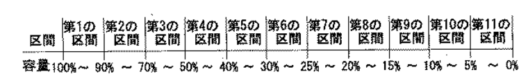
図2は、電池の全容量範囲を複数の容量区間に分割したときの分割例を示す図である。図2に示す例では、電池の全容量範囲0%〜100%を第1の区間から第11の区間まで11区間に分割している。図2に示されるように、第1の区間は電池残量が90%以上100%未満の区間、第2の区間は電池残量が70%以上90%未満の区間、第3の区間は電池残量が50%以上70%未満の区間、第4の区間は電池残量が40%以上50%未満の区間、第5の区間は電池残量が30%以上40%未満の区間、第6の区間は電池残量が25%以上30%未満の区間、第7の区間は電池残量が20%以上25%未満の区間、第8の区間は電池残量が15%以上20%未満の区間、第9の区間は電池残量が10%以上15%未満の区間、第10の区間は電池残量が5%以上10%未満の区間、第11の区間は電池残量が0%以上5%未満の区間である。また、この場合の境界容量は、各容量区間の下限の容量であり、90%、70%、50%、40%、30%、25%、20%、15%、10%、5%、及び0%である。 FIG. 2 is a diagram illustrating an example of division when the entire capacity range of the battery is divided into a plurality of capacity sections. In the example shown in FIG. 2, the total battery capacity range of 0% to 100% is divided into 11 sections from the first section to the eleventh section. As shown in FIG. 2, the first section is a section where the remaining battery level is 90% or more and less than 100%, the second section is a section where the remaining battery level is 70% or more and less than 90%, and the third section is a battery. A section in which the remaining battery level is 50% or more and less than 70%, a fourth section is a section in which the remaining battery capacity is 40% or more and less than 50%, a fifth section is a section in which the remaining battery capacity is 30% or more and less than 40%, Is the section where the remaining battery capacity is 25% or more and less than 30%, the seventh section is the section where the remaining battery capacity is 20% or more and less than 25%, and the eighth section is the remaining battery capacity of 15% or more but less than 20%. Section, the ninth section is a section where the remaining battery level is 10% or more and less than 15%, the tenth section is a section where the remaining battery level is 5% or more and less than 10%, and the eleventh section is a remaining battery level of 0% or more The interval is less than 5%. In addition, the boundary capacity in this case is the lower limit capacity of each capacity section, and is 90%, 70%, 50%, 40%, 30%, 25%, 20%, 15%, 10%, 5%, and 0%.
図1のグラフによれば、上記境界容量に対応する電圧はV1〜V11である。しかし、図1に示されたグラフ、すなわち電池残量と電池電圧との関係は電池の温度や出力電流の大きさによって変化するため、上記V1〜V11をそのまま参照電圧として採用すると、電池残量を正しく検出できない場合がある。よって、本実施の形態1による電池残量検出装置では、電池残量検出時の電池の温度が含まれる電池温度区間、及び電池残量検出時の電池の出力電流が含まれる電池電流区間に応じて異なる参照電圧を生成する。 According to the graph of FIG. 1, the voltages corresponding to the boundary capacitance are V1 to V11. However, since the graph shown in FIG. 1, that is, the relationship between the remaining battery level and the battery voltage changes depending on the temperature of the battery and the magnitude of the output current, if the above V1 to V11 are directly used as the reference voltage, the remaining battery level May not be detected correctly. Therefore, in the remaining battery level detection device according to the first embodiment, the battery temperature range including the battery temperature at the time of detecting the remaining battery level and the battery current period including the output current of the battery at the time of remaining battery level detection are determined. Different reference voltages.
同じ電池残量に対する電池電圧は、電池の温度が高いほど上昇し、電池の出力電流が大きいほど低下する。本実施の形態1による電池残量検出装置によって生成される参照電圧は、電池の温度が所定の温度で電池の出力電流が0A、すなわち無負荷の場合における電池電圧を基準電圧とした場合に、その基準電圧を、検出された電池温度区間と電池電流区間とに応じて補正して得られる電圧に等しい。以下に詳細に説明する。例えば、電池の温度が25℃、電池の出力電流が0Aの場合の電池の電圧を基準電圧とし、図1に示されるグラフが、電池の温度が25℃で出力電流が0Aの場合の電池残量と電池電圧との関係を示すグラフであるとき、上記各境界容量に対応する基準電圧は、V1〜V11である。表1は、その各境界容量と基準電圧V1〜V11との対応を示す。
Vnr=Vn+ΔVnt−ΔVni (1)
The battery voltage for the same remaining battery level increases as the battery temperature increases, and decreases as the battery output current increases. The reference voltage generated by the battery remaining amount detection device according to the first embodiment is obtained when the battery temperature is a predetermined temperature and the battery output current is 0 A, that is, when the battery voltage in the case of no load is used as the reference voltage, The reference voltage is equal to the voltage obtained by correcting the reference voltage according to the detected battery temperature interval and battery current interval. This will be described in detail below. For example, the battery voltage when the battery temperature is 25 ° C. and the battery output current is 0 A is the reference voltage, and the graph shown in FIG. 1 shows the remaining battery power when the battery temperature is 25 ° C. and the output current is 0 A. When it is a graph which shows the relationship between quantity and battery voltage, the reference voltages corresponding to each said boundary capacity are V1-V11. Table 1 shows the correspondence between the boundary capacitances and the reference voltages V1 to V11.
Vnr = Vn + ΔVnt−ΔVni (1)
本実施の形態1による電池残量検出装置では、電池の全容量範囲を複数の容量区間に分割することにより、図1に示された曲線グラフを、各容量区間における一次方程式で表す。そして、各容量区間において、電池の温度が1℃変化したときに変化する電池の電圧量、すなわち温度係数と、電池の出力電流が1A変化したときに変化する電池の電圧量、すなわち電池の内部抵抗が一定であると仮定する。これにより、式(1)に示されたΔVntは、検出された電池温度区間に対して定められた温度と基準温度との差をΔT、第nの容量区間における温度係数をRとすると、ΔTとRの積であるΔT×Rで求められる。ここで、電池温度区間に対して定められた温度とは、例えば、その電池温度区間の上限の温度である。また、電流による補正電圧ΔVniは、第nの容量区間における内部抵抗と、検出された電池電流区間に対して定められた電流との積で求められる。ここで、電池電流区間に対して定められた電流とは、例えば、その電池電流区間の上限の電流である。上述のように電池の全容量範囲を複数の容量区間に分割することにより、各容量区間における電池の残容量と電圧との関係を一次方程式で表すことができるので、各容量区間に対応する、電池の温度や電池の出力電流の大きさによって補正された電圧を容易に求めることができる。 In the battery remaining capacity detection device according to the first embodiment, the curve graph shown in FIG. 1 is expressed by a linear equation in each capacity section by dividing the entire capacity range of the battery into a plurality of capacity sections. In each capacity section, the battery voltage amount that changes when the battery temperature changes by 1 ° C., that is, the temperature coefficient, and the battery voltage amount that changes when the battery output current changes by 1 A, that is, the inside of the battery. Assume that the resistance is constant. Accordingly, ΔVnt shown in the equation (1) is expressed as ΔT, where ΔT is a difference between the temperature determined for the detected battery temperature interval and the reference temperature, and R is a temperature coefficient in the nth capacity interval. And R is a product of ΔT × R. Here, the temperature determined for the battery temperature section is, for example, the upper limit temperature of the battery temperature section. Further, the correction voltage ΔVni due to current is obtained by the product of the internal resistance in the nth capacity section and the current determined for the detected battery current section. Here, the current determined for the battery current section is, for example, the upper limit current of the battery current section. As described above, by dividing the total capacity range of the battery into a plurality of capacity sections, the relationship between the remaining capacity of the battery and the voltage in each capacity section can be expressed by a linear equation, and therefore corresponds to each capacity section. The voltage corrected by the battery temperature and the magnitude of the battery output current can be easily obtained.
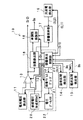
図3は、本実施の形態1による電池残量検出装置の構成例を示したブロック図である。図3に示されるように、電池残量検出装置10は、電池電圧検出部11、参照電圧生成部12、電圧比較回路13、温度区間検出部14、電流区間検出部15、容量検出部16、容量保持部17、単調性保証部18、及び充放電検出部19を備える。電池電圧検出部11は、電池の電圧を検出して、その電圧を電池電圧として出力する。参照電圧生成部12は、上述の参照電圧を生成して出力する。参照電圧生成部12は、電池残量検出装置10の外部から入力された外部制御信号Sr1に応じてその生成動作を開始又は停止する。電圧比較回路13はオペアンプからなり、電池電圧検出部11から出力された電池電圧と参照電圧生成部12から出力された参照電圧とを比較して、その電池電圧と参照電圧の大小関係に応じて2値の信号レベルの制御信号Sr2を出力する。なお、電圧比較回路13は、電圧比較部をなす。また、参照電圧生成部12、電圧比較回路13及び容量検出部16は、容量区間検出部をなす。
FIG. 3 is a block diagram showing a configuration example of the remaining battery level detection device according to the first embodiment. As shown in FIG. 3, the remaining battery
温度区間検出部14は、電池残量検出時の電池の温度が含まれる電池温度区間を検出する。この電池温度区間は、各電池の使用温度範囲を予め決められた数の区間に分割して得られる複数の温度区間のうちの1つである。図4は、上記使用温度範囲を複数の温度区間に分割したときの分割例を示す図である。図4では、電池の使用温度範囲である「−20℃以上〜70℃以下」を10℃毎に分割して得られる、第1の区間から第10の区間までの10区間を示す。具体的には、第1の区間は電池の温度が−20℃以下の区間(実質的には、−20℃の区間)、第2の区間は電池の温度が−20℃を超えてかつ−10℃以下の区間、第3の区間は電池の温度が−10℃を超えてかつ0℃以下の区間、第4の区間は電池の温度が0℃を超えてかつ10℃以下の区間、第5の区間は電池の温度が10℃を超えてかつ20℃以下の区間、第6の区間は電池の温度が20℃を超えてかつ30℃以下の区間、第7の区間は電池の温度が30℃を超えてかつ40℃以下の区間、第8の区間は電池の温度が40℃を超えてかつ50℃以下の区間、第9の区間は電池の温度が50℃を超えてかつ60℃以下の区間、第10の区間は電池の温度が60℃を超えてかつ70℃以下の区間である。温度区間検出部14は、電池残量検出時の電池の温度が上記複数の温度区間のいずれに含まれるかを検出し、電池温度区間を示すデータDaを参照電圧生成部12に出力する。なお、温度区間検出部14の構成及び動作については、後に詳細に説明する。
The temperature
電流区間検出部15は、電池残量検出時の電池の出力電流が含まれる電池電流区間を検出する。この電池電流区間は、電池の使用電流範囲を予め決められた数の区間に分割して得られる複数の電流区間のうちの1つである。図5は、電池の使用電流範囲を複数の電流区間に分割したときの分割例を示す図である。図5では、電池の使用電流範囲である「20mA以上200mA以下」を20mA毎に分割して得られる、第1の区間から第10の区間までの10区間を示す。具体的には、第1の区間は電池の電流が20mA以下の区間(実質的には、20mAの区間)、第2の区間は電池の電流が20mAを超えてかつ40mA以下の区間、第3の区間は電池の電流が40mAを超えてかつ60mA以下の区間、第4の区間は電池の電流が60mAを超えてかつ80mA以下の区間、第5の区間は電池の電流が80mAを超えてかつ100mA以下の区間、第6の区間は電池の電流が100mAを超えてかつ120mA以下の区間、第7の区間は電池の電流が120mAを超えてかつ140mA以下の区間、第8の区間は電池の電流が140mAを超えてかつ160mA以下の区間、第9の区間は電池の電流が160mAを超えてかつ180mA以下の区間、第10の区間は電池の温度が180mAを超えてかつ200mA以下の区間である。電流区間検出部15は、電池残量検出時の電池の出力電流が上記複数の電流区間のいずれに含まれるかを検出し、電池電流区間を示すデータDbを参照電圧生成部12に出力する。なお、電流区間検出部15の構成及び動作については、後に詳細に説明する。
The current
図3に示されるように、参照電圧生成部12は、容量検出制御部20、容量アドレスデコーダ21、電圧データメモリ22、及び参照電圧生成用D−Aコンバータ(以下、「DAC」という。)23を備える。電圧データメモリ22は、電池温度区間及び電池電流区間の組み合わせ毎に、各容量区間に対応した参照電圧を示すテーブルを有する。図4及び図5に示されるように、温度区間及び電流区間はそれぞれ10区間存在するので、電圧データメモリ22は、100個のテーブルを有する。なお、電圧データメモリ22は記憶部を、容量検出制御部20及び容量アドレスデコーダ21は選択部を、参照電圧生成用D−Aコンバータは出力部をそれぞれなす。
As shown in FIG. 3, the reference
容量検出制御部20には、電池残量検出装置10の外部から2値の信号レベルの容量制御信号Sr1が入力される。容量検出制御部20は、容量制御信号Sr1に応じて、その動作を開始又は停止する。さらに、図3に示されるように、容量検出制御部20は、容量制御信号Sr1の信号レベルに応じて、電池電圧検出部11、電圧比較回路13、温度区間検出部14、電流区間検出部15、単調性保証部18、充放電検出部19、容量アドレスデコーダ21、及び参照電圧生成用DAC23の各構成要素の動作を制御する。例えば、容量検出制御部20は、容量制御信号Sr1がHighレベル(Hレベル)のとき動作を開始し、容量制御信号Sr1がLowレベル(Lレベル)のとき動作を停止するものとする。この場合、容量検出制御部20は、Hレベルの容量制御信号Sr1が入力されると、上述の各構成要素に、それぞれ対応する所定の制御信号を出力し、それらの各構成要素の動作を開始させる。一方、容量検出制御部20は、Lレベルの容量制御信号Sr1が入力されると、それらの各構成要素の動作を停止させる。
A capacity control signal Sr1 having a binary signal level is input to the capacity
容量検出制御部20は、温度区間検出部14及び電流区間検出部15に対して、それぞれ対応する制御信号St1及びSm1を出力する。温度区間検出部14は、入力された制御信号St1の信号レベルに応じて、温度区間検出動作を開始又は停止し、電流区間検出部15は、入力された制御信号Sm1の信号レベルに応じて、電流区間検出動作を開始又は停止する。例えば、制御信号St1及びSm1がそれぞれHレベルのとき、温度区間検出部14及び電流区間検出部15がそれぞれ動作を開始し、制御信号St1及びSm1がそれぞれLレベルのとき、温度区間検出部14及び電流区間検出部15がそれぞれ動作を停止すると仮定すると、容量検出制御部20は、Hレベルの容量制御信号Sr1が入力されると、温度区間検出部14及び電流区間検出部15にそれぞれHレベルの制御信号St2,Sm2を出力する。温度区間検出部14は、Hレベルの制御信号St2が入力されると検出動作を開始し、温度区間データDaを出力する。また、電流区間検出部15は、Hレベルの制御信号Sm2が入力されると検出動作を開始し、電流区間データDbを出力する。以下の説明では、温度データDa及び電流データDbが、それぞれ第7区間及び第4区間を示すものとする。
The capacity
参照電圧生成部12では、容量区間毎に参照電圧を生成して出力する。具体的に、容量検出部21は、入力された容量制御信号Sr1がHレベルのとき、温度区間検出部14によって検出された温度データDaが示す電池温度区間と、電流区間検出部15によって検出された電流データDbが示す電池電流区間と、容量区間とを示すデータDrを容量区間毎に容量アドレスデコーダ21に出力する。例えば、説明をわかりやすくするために、整数p,q,n(1≦p,q≦10,1≦n≦11)を用いて、電池温度区間が第p区間であること、電池電流区間が第q区間であること、及び容量区間が第nの区間であることを示すデータDrを(p,q,n)で表すと、容量検出制御部20は、データDr(7,4,1)からデータDr(7,4,11)まで、データDr(7,4,n)を順次容量アドレスデコーダ21に出力する。また、容量検出制御部20は、データDr(7,4,n)を出力すると同時に、容量検出部16に対して、第nの容量区間を示すデータDsを出力する。容量検出部16は、容量検出制御部20から入力されたそのデータDsを、容量検出制御部20から次のデータDsが入力されるまで保持する。
The reference
容量アドレスデコーダ21は、容量検出制御部20から出力されたデータDrを用いて、電圧データメモリ22のアドレスを示すアドレスデータを生成する。このとき、容量アドレスデコーダ21は、入力されたデータDrに応じて、電圧データメモリ22に記憶された複数のテーブルの中から1つのテーブルを選択し、そのテーブルが記憶されているアドレスを示すデータを電圧データメモリ22に出力する。例えば、データDrが(7,4,n)の場合、容量アドレスデコーダ21は、各容量区間と参照電圧との関係を示す複数のテーブルの中から、電池温度区間が第7区間であり、かつ電池電流区間が第4区間である場合の各容量区間と参照電圧との関係を示す1つのテーブルを選択し、そのテーブルにおける第nの容量区間、すなわち第n番目の境界容量に対応する参照電圧のデータが記憶された電圧データメモリ22のアドレスを順次出力する。
The
電圧データメモリ22は、容量アドレスデコーダ21から出力されたアドレスデータが示すアドレスに格納された参照電圧のデータを参照電圧生成用DACに順次出力する。参照電圧生成用DAC23は、電圧データメモリ22から出力されたデジタルデータをアナログデータに変換し、そのアナログデータを参照電圧として、電圧比較回路13に出力する。
The
結果として、参照電圧生成部12は、各境界容量に対応する参照電圧V1r〜V11rを順次生成して出力する。本実施の形態1による電池残量検出装置において、参照電圧生成部12は、参照電圧を大きい順に生成して出力する。
As a result, the
上述したように、電圧比較回路13は、電池電圧検出部11から出力された電池電圧と参照電圧生成部12から順次出力された参照電圧とを比較して、その電池電圧と参照電圧の大小関係に応じて2値の信号レベルの制御信号Sr2を出力する。図3に示された電圧比較回路13は、電池電圧が参照電圧以上の場合にHレベルの制御信号Sr2を出力し、電池電圧が参照電圧未満の場合にLレベルの制御信号Sr2を出力する。参照電圧生成部12は、参照電圧を大きい順に出力するので、制御信号Sr2は、最初Lレベルであり、電池電圧が参照電圧以上になったとき、Hレベルになる。すなわち、電池残量は、制御信号Sr2が反転したとき、つまり制御信号Sr2がLレベルからHレベルに変化したときに比較されていた参照電圧に対応する容量区間に存在するとみなされる。なお、制御信号Sr2の初期レベルをLレベルに設定しておけば、電池残量が第1の区間に含まれる場合であっても、容量検出部16は、制御信号Sr2の信号レベルの反転を検出することができる。
As described above, the
制御信号Sr2は、容量検出部16に入力される。容量検出部16は、制御信号Sr2がHレベルになったとき、そのときに保持している容量区間のデータを、電池残量が含まれる容量区間を示すデータとして、容量保持部17及び単調性保証部18に出力する。
The control signal Sr2 is input to the
容量保持部17には、充放電検出部19から制御信号Sj2が入力される。充放電検出部19には、容量検出制御部20から制御信号Sj1が入力される。充放電検出部19は、例えばHレベルの制御信号Sj1が入力されると動作を開始し、電池が充電中であるか放電中であるかを検出して、その検出結果を示す制御信号Sj2を容量保持部17に出力する。例えば、充放電検出部19は、電池が充電中であるときLレベルの制御信号Sj2を出力し、電池が放電中であるときHレベルの制御信号Sj2を出力することによって、電池の充放電の検出結果を示す。なお、充放電検出部19の構成及び動作については、後に詳細に説明する。
A control signal Sj2 is input to the
容量保持部17は、その制御信号Sj2によって、電池が充電中であるか又は放電中であるかを検知する。容量保持部17は、制御信号Sj2が、一旦Hレベルになって、次にLレベルになるまでの間、すなわち電池が放電中の間に、容量検出部16が容量区間データを出力する毎に、電池が放電を開始してからその容量区間データが出力されるまでの間に容量検出部16が出力した容量区間データのうち、最小の容量を含む最小容量区間を示す容量区間データを、単調性保証部18に出力する。単調性保証部18は、容量検出部16から出力された第1の容量区間データと容量保持部17から出力された第2の容量区間データとを比較する。単調性保証部18は、第1の容量区間データが示す容量区間に含まれる容量が、第2の容量区間データが示す容量区間に含まれる容量より小さいときは、電池の残容量が含まれる容量区間を示すデータDpとして、その第1の容量区間データを外部に出力する。
The
また、単調性保証部18は、第1の容量区間データが示す容量区間が、第2の容量区間データが示す容量区間より大きいときは、データDpとして、その第2の容量区間データを外部に出力する。また、容量保持部17は、制御信号Sj2がHレベルからLレベルになり、次にHレベルになるとき、すなわち電池が再び放電を開始するとき、電池の最大容量を含む最大容量区間を示す容量区間データを出力する。容量保持部17は、上述の動作を行うために、例えば、容量検出部16が出力する容量区間データを記憶する第1のメモリと、最大容量区間を示す容量区間データを記憶する第2のメモリの2つのメモリを備える構成であってよい。その場合、容量保持部17は、容量検出部16から出力された容量区間データが第1のメモリに記憶された容量区間データよりも小さい容量を含む容量区間を示すなら、その容量区間検出部16から出力された容量区間データによって、第1のメモリに記憶された容量区間データを書き換える。また、制御信号Sj2がHレベルからLレベルになり、次にHレベルになった直後は、第2のメモリに記憶された容量区間データを出力する。
Further, when the capacity section indicated by the first capacity section data is larger than the capacity section indicated by the second capacity section data, the
以上から、本実施の形態1による電池残量検出装置10は、例えば、電池をしばらく使用しないため、電池電圧が上昇したような場合にも、あたかも電池残量が増加したかのような誤った検出が行われることを防止することができる。結果として、上記電池残量を含む残容量区間の安定した表示が可能となる。なお、単調性保証部18は、容量区間出力部をなす。
From the above, the remaining battery
なお、上述の電池残量検出装置10においては、参照電圧生成部12が参照電圧を大きい順に生成して出力したが、境界容量に対応する参照電圧を小さい順に生成して出力してもよい。その場合、境界容量は、各容量区間の上限の容量である。このとき、電圧比較回路13が、電池電圧が参照電圧より大きい場合にHレベルの制御信号Sr1を出力し、電池電圧が参照電圧以下のときLレベルの制御信号Sr1を出力するとすれば、容量検出部16は、制御信号Sr1がLレベルになったとき、そのときに保持している容量区間のデータを、電池残量が含まれる容量区間を示すデータとして、容量保持部17及び単調性保証部18に出力する。
In the above-described battery remaining
また、本実施の形態1による電池残量検出装置10において、電池電圧検出部11は、検出された電池の電圧をそのまま電池電圧として出力したが、検出した電池の電圧に比例した電圧を電池電圧として出力してもよい。その場合、参照電圧生成部12が生成する参照電圧も、その比例係数に応じて変化する。
Further, in the remaining battery
なお、本実施の形態1による電池残量検出装置10において、容量アドレスデコーダ21を除去してもよい。その場合、容量検出制御部20は、温度データDaと電流データDbとから電圧データメモリ22に記憶された複数のテーブルのうち1つのテーブルを選択し、かつそのテーブルが記憶されているアドレスを示すアドレスデータを出力するように構成されなければならない。
Note that the
また、電圧比較回路13が出力する制御信号Sr2は、電池残量を検出したことを示す容量検出結果信号として、外部に出力される。外部の装置は、制御信号Dr1の信号レベルの反転によって電池残量が検出されたことを検知すると、容量制御信号Sr1を用いて、参照電圧生成部12の比較電圧生成動作を停止させることができる。参照電圧生成部12は、容量制御信号Sr1がHレベルのときだけ、すなわち、電池残量検出が必要なときだけ動作し、かつ他の構成要素を動作させるので、電池残量検出装置10の消費電力を低減することができる。
The control signal Sr2 output from the
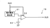
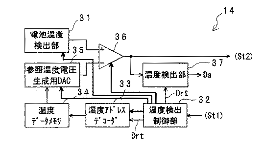
以下に、温度区間検出部14、電流区間検出部15、及び充放電検出部19の構成を詳細に説明する。まず、温度区間検出部14について説明する。図6は、温度区間検出部14の構成例を示したブロック図である。図6に示されるように、温度区間検出部14は、電池温度検出部31、温度検出制御部32、温度アドレスデコーダ33、温度データメモリ34、参照温度電圧生成用DAC35、温度比較回路36、及び温度検出部37を備える。電池温度検出部31は、電池の近傍に取り付けられた温度センサによって電池の温度を測定し、その測定された温度を電圧に変換して、その変換後の電圧を電池温度電圧として出力する。ここで、電池温度電圧は電池の温度に比例する。温度比較回路36はオペアンプからなり、電池温度検出部31から出力された電池温度電圧と、参照温度電圧生成用DAC35から出力された参照温度電圧とを比較して、それらの電圧の大小関係に応じて2値の信号レベルの制御信号St2を出力する。温度データメモリ34は、各温度区間に対応した参照温度電圧を示すテーブルを記憶する。具体的に、温度データメモリ34に記憶されるテーブルは、電池の温度が、図4に示された各温度区間の上限の温度、すなわち−20℃、−10℃、0℃、10℃、20℃、30℃、40℃、50℃、60℃及び70℃のそれぞれである場合に電池温度検出部31によって検出される電圧に等しい電圧を示す。
Below, the structure of the temperature
温度検出制御部32には、容量検出制御部20から温度区間検出動作の開始及び停止を制御する温度制御信号St1が入力される。温度検出制御部32は、温度制御信号St1に応じて、その動作を開始又は停止するとともに、電池温度検出部31、参照温度電圧生成用DAC34、及び温度比較回路36の各構成要素の動作を制御する。例えば、Hレベルの温度制御信号St1が温度区間検出動作の開始を示し、Lレベルの温度制御信号St1が温度区間検出動作の停止を示すとすると、温度検出制御部32は、Hレベルの温度制御信号St1が入力されると、検出動作を開始するとともに、上述の各構成要素に対応する所定の制御信号をそれぞれ出力して、各構成要素の動作を開始させる。温度検出制御部32は、Hレベルの温度制御信号St1が入力されると、各温度区間を示すデータDrtを、温度アドレスデコーダ33及び温度検出部37に出力する。このとき、温度検出制御部32は、温度区間に含まれる温度が低い順に、各温度区間を示すデータDrtを出力する。温度検出部37は、温度検出制御部32から入力されたそのデータDrtを、温度検出制御部32から次のデータDrtが入力されるまで保持する。
The temperature
温度アドレスデコーダ33は、温度検出制御部32から出力されたデータDrtを用いて、そのデータDrtが示す各温度区間に対応した参照温度電圧が記憶されている温度データメモリ24のアドレスを示すアドレスデータを生成して出力する。温度データメモリ34は、上記アドレスデータが示すアドレスに格納されている電圧データを順次参照温度電圧生成用DAC35に出力する。参照温度電圧生成用DAC35は、温度データメモリ34から出力されたデジタルデータをアナログデータに変換し、そのアナログデータを参照温度電圧として、温度比較回路36に出力する。結果として、参照温度電圧生成用DAC35は、各温度区間に対応する参照温度電圧を小さい順に順次出力する。
The
上述したように、温度比較回路36は、電池温度検出部31から出力された電池温度電圧と参照温度電圧生成用DAC35から順次出力された参照温度電圧とを比較して、その電池温度電圧と参照温度電圧との大小関係に応じて制御信号St2を出力する。図6に示された温度比較回路36は、電池温度電圧が参照温度電圧より大きい場合にHレベルの制御信号St2を出力し、電池温度電圧が参照温度電圧以下のときLレベルの制御信号St2を出力する。参照温度電圧生成用DAC35は、参照温度電圧を小さい順に出力するので、制御信号St2は、最初Hレベルであり、参照温度電圧生成用DAC35から出力される参照温度電圧が電池温度電圧以上になったとき、Lレベルになる。
As described above, the
温度検出部16は、制御信号St2がLレベルになったとき、そのときに保持している温度区間のデータを、電池の温度が含まれる温度区間を示すデータDaとして出力する。また、温度比較回路36が出力する制御信号St2は、電池温度を検出したことを示す温度検出結果信号として、電池残量検出装置10の外部に出力される。
When the control signal St2 becomes the L level, the
なお、制御信号St2の初期信号レベルをHレベルに設定しておけば、電池温度が第1の区間に含まれる場合であっても、温度検出部37は、制御信号St2の信号レベルの反転を検出することができる。
If the initial signal level of the control signal St2 is set to the H level, the
温度区間検出部14において、温度検出制御部32は、容量検出制御部20から入力される温度制御信号St1に応じて、その検出動作を開始又は停止させるとともに、温度区間検出部14の他の構成要素の動作も制御する。これにより、温度区間検出部32は、温度区間検出が必要なときだけ動作することが可能となるので、検出に使用する電力を低減することができる。その結果、電池残量検出装置10の消費電力を低減することができる。
In the temperature
また、上述の温度区間検出部14によれば、電池残量検出時の電池の温度が含まれる温度区間を容易にかつ正確に取得することができる。
Moreover, according to the above-mentioned temperature
次に、電流区間検出部15について説明する。図7は、電流区間検出部15の構成例を示したブロック図である。図7に示されるように、電流区間検出部15は、電池電流検出部41、電流検出制御部42、電流アドレスデコーダ43、電流データメモリ44、参照電流電圧生成用DAC45、電流比較回路46、電流検出部47を備える。電池電流検出部41は、電池の出力電流を一定時間測定しその平均電流を電圧に変換し、電池電流電圧として出力する。電流比較回路46はオペアンプからなり、電池電流検出部41から出力された電池電流電圧と、参照電流電圧生成用DAC45から出力された参照電流電圧とを比較して、それらの電圧の大小関係に応じて2値の信号レベルの制御信号Sm2を出力する。電流データメモリ44は、各電流区間に対応した参照電流電圧を示すテーブルを記憶する。具体的に、電流データメモリ44に記憶されるテーブルは、電池の電流が、図5に示された各電流区間の上限の電流、すなわち20mA、40mA、60mA、80mA、100mA、120mA、140mA、160mA、180mA及び200mAのそれぞれである場合に電池電流検出部41によって検出される電圧に等しい電圧を示す。
Next, the current
電流検出制御部42には、容量検出制御部20から電流区間検出動作の開始及び停止を制御する電流制御信号Sm1が入力される。電流検出制御部42は、電流制御信号Sm1に応じて、その動作を開始又は停止するとともに、電池電流検出部41、参照電流電圧生成用DAC44、及び電流比較回路36の各構成要素の動作を制御する。例えば、Hレベルの電流制御信号Sm1が電流区間検出動作の開始を示し、Lレベルの電流制御信号Sm1が電流区間検出動作の停止を示すとすると、電流検出制御部42は、Hレベルの電流制御信号Sm1が入力されると、検出動作を開始するとともに、上述の各構成要素に対応する所定の制御信号をそれぞれ出力して、各構成要素の動作を開始させる。電流検出制御部42は、電流制御信号Sm1がHレベルであるとき、各電流区間を示すデータDmを、電流アドレスデコーダ43及び電流検出部47に出力する。このとき、電流検出制御部42は、電流区間に含まれる電流が小さい順に、各電流区間を示すデータDrmを出力する。電流検出部47は、電流検出制御部42から入力されたそのデータDrmを、電流検出制御部42から次のデータDrmが入力されるまで保持する。
The current
電流アドレスデコーダ43は、電流検出制御部42から出力されたデータDrmを用いて、そのデータDrmが示す各電流区間に対応した参照電流電圧が記憶されている電流データメモリ44のアドレスを示すアドレスデータを生成して出力する。電流データメモリ44は、上記アドレスデータが示すアドレスに格納されている電圧データを順次参照電流電圧生成用DAC45に出力する。参照電流電圧生成用DAC45は、電流データメモリ44から出力されたデジタルデータをアナログデータに変換し、そのアナログデータを参照電流電圧として、電流比較回路46に出力する。電池電流電圧は電池の電流が大きいほど大きいので、参照電流電圧生成用DAC45は、各電流区間に対応する参照電流電圧を小さい順に順次出力する。
The
上述したように、電流比較回路46は、電池電流検出部41から出力された電池電流電圧と参照電流電圧生成用DAC45から順次出力された参照電流電圧とを比較して、その電池電流電圧と参照電流電圧の大小関係に応じて2値の信号レベルの制御信号Sm2を出力する。図7に示された電流比較回路46は、電池電流電圧が参照電流電圧より大きい場合にHレベルの制御信号Sm2を出力し、電池電流電圧が参照電流電圧以下のときLレベルの制御信号Sm2を出力する。参照電流電圧生成用DAC45は、参照電流電圧を小さい順に出力するので、制御信号Sm2は、最初Hレベルであり、参照電流電圧が電池電流電圧以上になったときLレベルになる。
As described above, the
電流検出部47は、制御信号Sm2がLレベルになったとき、そのときに保持している電流区間のデータを、電池の電流が含まれる電流区間を示すデータDbとして出力する。また、電流比較回路46が出力する制御信号Sm2は、電池電流を検出したことを示す電流検出結果信号として、電池残量検出装置10の外部に出力される。
When the control signal Sm2 becomes L level, the
電流区間検出部15において、電流検出制御部42は、容量検出制御部20から入力される電流制御信号Sm1に応じて、その検出動作を開始又は停止させるとともに、電流区間検出部15の他の構成要素の動作も制御する。これにより、電流区間検出部15は、電流区間検出が必要なときだけ動作することが可能となるので、検出に使用する電力を低減することができる。その結果、電池残量検出装置10の消費電力を低減することができる。
In the current
また、上述の電流区間検出部15によれば、電池残量検出時の電池の出力電流が含まれる電流区間を容易にかつ正確に取得することができる。
Moreover, according to the above-described current
次に、充放電検出部19について説明する。図8は、充放電検出部19の構成例を示したブロック図である。充放電検出部19は、電池電流検出部51、充電回数比較回路52、及び極性基準電圧生成部53を備える。電池電流検出部51は、電池の電流を一定時間測定してその平均電流を電圧に変換し、変換後の電圧を電流電圧として出力する。電池電流検出部51は、電池の電流が電池を充電する方向に流れているとき、負の電圧を出力し、電池の電流が電池を放電する方向に流れているとき、正の電圧を出力する。極性基準電圧生成部53は、電池の電流が充電方向に流れていることを識別するための充電基準電圧を生成して出力する。
Next, the charge /
充電回数比較回路52は、電池電流検出部51から出力された電流電圧と極性基準電圧生成部53から出力された充電基準電圧とを比較し、その電流電圧と充電基準電圧との大小関係を示す2値の信号レベルの制御信号Sj2を出力する。例えば、充電回数比較回路52は、電流電圧が充電基準電圧より大きい場合にHレベルの制御信号Sj2を出力し、電流電圧が充電基準電圧以下のときLレベルの制御信号Sj2を出力する。電流電圧は電池の電流を一定時間測定した場合の平均電流に比例するので、電池が放電中の場合、電流電圧は上記充電基準電圧よりも大きくなる。充電回数比較回路52が出力する制御信号Sj2は、容量保持部17に入力される。
The number-of-
なお、電池電流検出部51は、容量検出制御部20から出力された制御信号Sj1によって、その動作の開始又は停止が制御される。また、充電回数比較回路52も、容量検出制御部20から出力された制御信号Sj1によって、その動作の開始又は停止が制御される。
The battery
なお、本実施の形態1による電池残量検出装置10では、電流区間検出部15と充放電検出部19とで異なる電池電流検出部41,51を用いたが、同じ電池電流検出部を用いてもよい。同じ電池電流検出部を用いれば、電池残量検出回路10の回路規模をより小さくすることができる。
In the remaining battery
本実施の形態1による電池残量検出装置10では、電池の全容量範囲を11区間、電池の使用温度範囲及び使用電流範囲をそれぞれ10区間に分割した場合について説明したが、それぞれの分割数はそれらに限定されるものではなく、任意の分割数であってよい。また、それらの分割数は、全部同じでも一部同じであってもよく、全部異なってもよい。
In the battery remaining
また、電池の全容量を分割して得られる各容量区間の容量幅は任意であってよい。ただし、電池電圧と電池残量との関係が電池の温度及び電池の出力電流によってそれぞれ変化する割合は、電池残量が大きい領域では小さく、電池残量が小さい領域では大きいため、容量区間の容量幅は、電池残量が大きい領域では大きく、電池残量が小さい領域では小さい方が好ましい。また、電池残量が大きい領域は、電池の充電を急ぐ必要はないので、おおまかに分割されていても、ユーザにとって大きな問題は生じない。 The capacity width of each capacity section obtained by dividing the total capacity of the battery may be arbitrary. However, the rate at which the relationship between the battery voltage and the remaining battery charge varies depending on the battery temperature and the output current of the battery is small in the high battery charge area and large in the low battery charge area. The width is preferably large in a region where the remaining battery level is large and small in a region where the remaining battery level is small. Moreover, since it is not necessary to rush to charge the battery in the area where the remaining battery level is large, even if the battery is roughly divided, no big problem occurs for the user.
本実施の形態1による電池残量検出装置は、電池電圧と内部で予め生成した参照電圧とを比較するだけで、すなわち電池電圧を検出するだけで、電池残量の検出が可能であるので、電池残量を容易に検出することができる。 Since the remaining battery level detection device according to the first embodiment can detect the remaining battery level only by comparing the battery voltage with a reference voltage generated in advance, that is, by detecting the battery voltage. The remaining battery level can be easily detected.
また、本実施の形態1による電池残量検出装置は、電池の温度が含まれる温度区間、及び電池の出力電流が含まれる電流区間に応じて、検出した電池電圧から電池の残容量が含まれる容量区間を検出する。よって、本実施の形態1による電池残量検出装置は、電池の電池残量と電池電圧との関係を示す1次元のテーブルを、使用温度範囲を分割して得られる温度区間数と使用電流範囲を分割して得られる電流区間数とを積算した数だけ有する。以上から、本実施の形態1による電池残量検出装置は、容量区間数、温度区間数、及び電流区間数を積算した数の電圧データを記憶するため、容量区間数、温度区間数、及び電流区間数をそれぞれ適当に選択すれば、記憶する電圧データの数を、従来の電池残量検出装置が記憶する電圧データの数よりも大幅に低減することが可能である。よって、電池の電流と電圧の関係を示す2次元のデータテーブルを電池の温度毎に複数備える従来の電池残量検出装置と比較して、メモリの容量を大幅に節約することができる。 In addition, the remaining battery level detection device according to the first embodiment includes the remaining battery capacity from the detected battery voltage in accordance with the temperature interval including the battery temperature and the current interval including the battery output current. Detect capacity interval. Therefore, the remaining battery level detection device according to the first embodiment is configured to obtain a one-dimensional table indicating the relationship between the remaining battery level and the battery voltage of the battery, the number of temperature sections obtained by dividing the use temperature range, and the use current range. And the number of current sections obtained by dividing. From the above, the battery remaining amount detection device according to the first embodiment stores the voltage data of the number obtained by integrating the number of capacity sections, the number of temperature sections, and the number of current sections, so the number of capacity sections, the number of temperature sections, and the current If the number of sections is appropriately selected, the number of voltage data to be stored can be significantly reduced from the number of voltage data stored by the conventional battery remaining amount detection device. Therefore, the memory capacity can be greatly saved as compared with the conventional battery remaining amount detecting device having a plurality of two-dimensional data tables showing the relationship between the battery current and the voltage for each battery temperature.
上記のように、本実施の形態1による電池残量検出装置は、従来必要であった電池の電流と電圧の関係を示す2次元のデータテーブルを電池の温度毎に複数備える必要がないので、大幅なメモリ容量の節約が可能である。また、本実施の形態1による電池残量検出装置は、電池の温度及び電池の出力電流を反映した参照電圧を生成できるので、従来の電池残量検出と同等以上の検出精度を保持することができる。以上から、本実施の形態1による電池残量検出装置は、従来の電池残量検出装置よりも小さい回路面積で、従来の電池残量検出装置と同等以上の検出精度を実現することができる。 As described above, the remaining battery level detection device according to the first embodiment does not need to include a plurality of two-dimensional data tables for each battery temperature that indicate the relationship between the battery current and voltage, which has been conventionally required. Significant memory capacity savings are possible. Moreover, since the battery remaining amount detection apparatus according to the first embodiment can generate a reference voltage reflecting the battery temperature and the battery output current, it can maintain a detection accuracy equal to or higher than that of the conventional battery remaining amount detection. it can. From the above, the remaining battery level detection device according to the first embodiment can realize detection accuracy equivalent to or higher than that of the conventional remaining battery level detection device with a smaller circuit area than the conventional remaining battery level detection device.
(実施の形態2)
以下に、本発明の実施の形態2による電池残量検出装置について説明する。本実施の形態2による電池残量検出装置60は、電池の温度が含まれる温度区間及び電池の出力電流が含まれる電流区間に加えて、電池の充電回数によっても異なる参照電圧を生成する。電池の温度が例えば25℃等の所定の温度、電池の電流が0A、及び充電回数が0回の場合の電池電圧である第nの容量区間に対応する基準電圧Vnに対して、充電回数による補正電圧をΔVnkとする。この補正電圧ΔVnkは、充電回数と、第nの容量区間における電圧変化の劣化係数との積で求められる。充電回数が増加すると、電池の電圧は低下するので、各境界容量における比較電圧Vnrは、以下の式(2)で表される。
Vnr=Vn+ΔVnt−ΔVni−ΔVnk (2)
これにより、本実施の形態2による電池残量検出装置は、電池の充電回数によってその電池の電圧と電池の残容量の関係が変化しても電池残量を正しく検出することができる。
(Embodiment 2)
Below, the battery remaining charge detection apparatus by Embodiment 2 of this invention is demonstrated. The battery remaining
Vnr = Vn + ΔVnt−ΔVni−ΔVnk (2)
Thereby, the remaining battery level detection device according to the second embodiment can correctly detect the remaining battery level even if the relationship between the voltage of the battery and the remaining capacity of the battery changes depending on the number of times the battery is charged.
図9は、本実施の形態2による電池残量検出装置の構成例を示したブロック図である。図9に示された電池残量検出装置60は、図3に示された電池残量検出装置10に充電回数生成部61が追加された構成をしている。充電回数生成部61は、電池の出力電流から電池の充電を検知し、充電動作が発生した回数を保持すると共に、保持した回数を示す回数データDcを出力する。なお、この充電回数生成部61も、外部制御信号Sr1に応じて容量検出制御部20が出力した制御信号Sk1によってその動作の開始又は停止が制御される。
FIG. 9 is a block diagram showing a configuration example of the remaining battery level detection device according to the second embodiment. The remaining battery
図10は、充電回数生成部61の構成例を示したブロック図である。充電回数生成部61は、図8で示された充放電検出部19に、充電回路保持部54を追加した構成をしている。上述したように、充電回数比較回路52は、電池電流検出部51から出力された電流電圧と極性基準電圧生成部53から出力された充電基準電圧とを比較し、その電流電圧と充電基準電圧の大小関係を示す2値の信号レベルの制御信号Sk2を出力する。例えば、充電回数比較回路52は、電流電圧が充電基準電圧より大きい場合にHレベルの制御信号Sk2を出力し、電流電圧が充電基準電圧以下のときLレベルの制御信号Sk2を出力する。充電回数保持部54は、充電回数比較回路52が反転した回数、すなわち制御信号Sk2がHレベルからLレベルに変化した回数をカウントして、そのカウント数を充電回数として保持すると共に、その充電回数を示すデータを回数データDcとして出力する。
FIG. 10 is a block diagram illustrating a configuration example of the charge
上述したように、充電回数生成部61は、容量検出制御部20が出力した制御信号Sk1によってその動作の開始又は停止が制御される。具体的に、電池電流検出部51及び充電回数比較回路52は、容量検出制御部20から出力された制御信号Sk1によって、その動作の開始又は停止がそれぞれ制御される。
As described above, the start or stop of the operation of the charge
電圧データメモリ22は、温度区間、電流区間、及び充電回数の組み合わせ毎に、各境界容量に対応した参照電圧を示すテーブルを記憶する。すなわち、図4及び図5に示されるように温度区間及び電流区間がそれぞれ10区間あり、その電池の充電回数が500回とすると、10×10×500個のテーブルを記憶する。
The
さらに、充電回数生成部61は、電池が充電中であるか放電中であるかを検出して、その検出結果を示す制御信号Sk2を容量保持部17に出力する。容量保持部17は、制御信号Sk2がHレベルからLレベルになり、次にHレベルになるとき、すなわち電池が再び放電を開始するとき、電池の最大容量を含む最大容量区間を示す容量区間データを出力する。
Furthermore, the charge
以上のように、電池の充電回数に応じて異なる参照電圧を生成することにより、何度も繰り返して使用する場合の電池の劣化特性を反映させることが可能になる。 As described above, by generating different reference voltages depending on the number of times the battery is charged, it becomes possible to reflect the deterioration characteristics of the battery when used repeatedly over and over.
本実施の形態2による電池残量検出装置は、実施の形態1による電池残量検出装置と同一の効果を得ることができるとともに、従来必要であった電池の電流と電圧の関係を示す2次元のデータテーブルを電池の温度毎に複数備える必要がないので、大幅なメモリ容量の節約が可能である。また、本実施の形態2による電池残量検出装置は、電池の温度及び電池の出力電流に加えて、電池の充電回数を反映した参照電圧を生成できるので、従来よりも電池残量検出の検出精度を向上させることができる。 The battery remaining amount detection device according to the second embodiment can obtain the same effect as the battery remaining amount detection device according to the first embodiment, and two-dimensionally shows the relationship between the current and voltage of the battery that has been conventionally required. Since there is no need to provide a plurality of data tables for each battery temperature, a significant memory capacity saving can be achieved. In addition, the battery remaining amount detection device according to the second embodiment can generate a reference voltage reflecting the number of times the battery is charged in addition to the battery temperature and the battery output current. Accuracy can be improved.
10 電池残量検出装置
11 電池電圧検出部
12 参照電圧生成部
13 電圧比較回路
14 温度区間検出部
15 電流区間検出部
16 第1の容量データ保持部
17 第2の容量データ保持部
18 単調性保証部
19 充放電検出部
20 容量検出制御部
21 容量アドレスデコーダ
22 電圧データメモリ
23 参照電圧生成用DAC
DESCRIPTION OF
Claims (29)
前記電池の温度を検出し、その検出した温度があらかじめ設定された温度範囲である各温度区間のいずれに含まれるかを検出する温度区間検出部と、
前記電池の電流を検出し、その検出した電流があらかじめ設定された電流範囲である各電流区間のいずれに含まれるかを検出する電流区間検出部と、
前記電池の電圧とその電池の残容量区間の関係を示す複数のテーブルを有し、前記温度区間検出部で検出された温度区間及び前記電流区間検出部で検出された電流区間に応じてその複数のテーブルの中から1つのテーブルを選択し、その選択したテーブルを用いて、入力された前記電池電圧が各残容量区間のいずれに含まれるかを検出する容量区間検出部と
を備えることを特徴とする電池残量検出装置。 A remaining battery level detection device for detecting a remaining battery capacity,
A temperature interval detection unit for detecting the temperature of the battery and detecting which of the temperature intervals the detected temperature is in a preset temperature range;
A current interval detector that detects the current of the battery and detects which of the current intervals is a preset current range;
A plurality of tables showing the relationship between the battery voltage and the remaining capacity section of the battery, and the plurality of tables according to the temperature section detected by the temperature section detector and the current section detected by the current section detector; And a capacity section detecting unit that detects which of the remaining battery capacity sections the input battery voltage is selected by using the selected table. The remaining battery level detection device.
前記容量区間検出部は、前記温度区間検出部で検出された温度区間、前記電流区間検出部で検出された電流区間、及び前記充電回数検出部で検出された充電回数に応じて前記複数のテーブルの中から1つのテーブルを選択することを特徴とする請求項1に記載の電池残量検出装置。 A charge number detection unit for detecting the number of charge times of the battery;
The capacity section detecting unit includes the plurality of tables according to the temperature section detected by the temperature section detecting unit, the current section detected by the current section detecting unit, and the number of charging times detected by the charging number detecting unit. The remaining battery level detection device according to claim 1, wherein one table is selected from the table.
前記容量区間検出部は、
前記複数のテーブルを有し、前記温度区間検出部で検出された温度区間及び前記電流区間検出部で検出された電流区間に応じて前記複数のテーブルの中から1つのテーブルを選択し、その選択したテーブルが示す前記境界容量毎の電圧を参照電圧として順次生成し出力する参照電圧生成部と、
入力された前記電池電圧と前記参照電圧生成部によって出力された参照電圧とを比較して、比較する毎にその比較結果に応じた第1の制御信号を出力する電圧比較部と、
前記電圧比較部が所定の第1の制御信号を出力すると、比較されていた参照電圧に対応する前記残容量区間を、前記電池残量を示す残容量区間として出力する容量検出部と
を備えることを特徴とする請求項1に記載の電池残量検出装置。 The plurality of tables respectively indicate a boundary capacity that is an upper limit or a lower limit capacity of each remaining capacity section, and a voltage set for each boundary capacity,
The capacity section detector is
The plurality of tables are selected, and one table is selected from the plurality of tables according to the temperature interval detected by the temperature interval detection unit and the current interval detected by the current interval detection unit, and the selection is performed. A reference voltage generator that sequentially generates and outputs a voltage for each of the boundary capacitances indicated by the table as a reference voltage;
A voltage comparison unit that compares the input battery voltage with the reference voltage output by the reference voltage generation unit and outputs a first control signal according to the comparison result each time the comparison is made;
A capacity detector that outputs the remaining capacity section corresponding to the compared reference voltage as a remaining capacity section indicating the remaining battery capacity when the voltage comparison section outputs a predetermined first control signal; The battery remaining amount detection apparatus of Claim 1 characterized by these.
前記複数のテーブルを記憶する記憶部と、
前記温度区間検出部で検出された温度区間及び前記電流区間検出部で検出された電流区間に応じてその複数のテーブルの中から1つのテーブルを選択する選択部と、
選択された前記テーブルが示す前記境界容量毎の電圧を参照電圧として順次生成し出力する出力部と
を備えることを特徴とする請求項4に記載の電池残量検出装置。 The reference voltage generator is
A storage unit for storing the plurality of tables;
A selection unit that selects one table from the plurality of tables according to the temperature interval detected by the temperature interval detection unit and the current interval detected by the current interval detection unit;
The battery remaining amount detection apparatus according to claim 4, further comprising: an output unit that sequentially generates and outputs a voltage for each of the boundary capacities indicated by the selected table as a reference voltage.
前記電池の温度の検出を行い、検出した温度に比例した電圧である温度電圧を生成して出力する電池温度検出部と、
電池の温度と温度電圧との関係を示すテーブルを有し、そのテーブルと検出された前記温度電圧とを用いて、前記電池の温度があらかじめ設定された温度範囲である各温度区間のいずれに含まれるかを検出して出力する第1の区間検出部と
を備えることを特徴とする請求項1、4及び5のいずれかに記載の電池残量検出装置。 The temperature section detector is
A battery temperature detector that detects the temperature of the battery and generates and outputs a temperature voltage that is proportional to the detected temperature; and
It has a table showing the relationship between the temperature of the battery and the temperature voltage, and using the table and the detected temperature voltage, the temperature of the battery is included in any of the temperature sections that are a preset temperature range The battery remaining amount detection apparatus according to claim 1, further comprising: a first section detection unit that detects and outputs whether the battery is discharged.
前記各温度区間の上限又は下限の温度である境界温度、及びその境界温度毎に設定された電圧を示すテーブルを有し、そのテーブルが示す前記境界温度毎の電圧を参照温度電圧として順次生成して出力する参照温度電圧生成部と、
検出された前記温度電圧と出力された前記各参照温度電圧とを比較して、比較する毎にその比較結果に応じた第2の制御信号を出力する温度電圧比較部と、
前記温度電圧比較部が所定の第2の制御信号を出力すると、比較されていた参照温度電圧に対応する前記温度区間を、前記電池温度が含まれる温度区間として出力する温度検出部と
を備えることを特徴とする請求項6に記載の電池残量検出装置。 The first section detector is
It has a table showing the boundary temperature that is the upper limit or lower limit temperature of each temperature section and the voltage set for each boundary temperature, and the voltage for each boundary temperature indicated by the table is sequentially generated as a reference temperature voltage. A reference temperature voltage generator that outputs
A temperature voltage comparison unit that compares the detected temperature voltage with each of the output reference temperature voltages and outputs a second control signal according to the comparison result each time the comparison is made;
A temperature detection unit that outputs the temperature interval corresponding to the compared reference temperature voltage as a temperature interval including the battery temperature when the temperature voltage comparison unit outputs a predetermined second control signal; The battery remaining amount detection apparatus of Claim 6 characterized by these.
前記電池の出力電流の検出を行い、その検出した出力電流に比例した電圧である第1の電流電圧を生成して出力する第1の電池電流検出部と、
電池の出力電流と電流電圧との関係を示したテーブルを有し、そのテーブルと検出された前記第1の電流電圧とを用いて、前記電池の出力電流があらかじめ設定された電流範囲である各電流区間のいずれに含まれるかを検出して出力する第2の区間検出部と
を備えることを特徴とする請求項1、及び請求項4から7のいずれかに記載の電池残量検出装置。 The current section detector is
A first battery current detector for detecting the output current of the battery, and generating and outputting a first current voltage that is a voltage proportional to the detected output current;
Each table has a table showing the relationship between the output current of the battery and the current voltage, and the output current of the battery is a preset current range using the table and the detected first current voltage. The battery remaining amount detection apparatus according to claim 1, further comprising: a second section detection unit that detects and outputs which of the current sections is included.
前記各電流区間の上限又は下限の電流である境界電流、及びその境界電流毎に設定された電圧を示すテーブルを有し、そのテーブルが示す前記境界電流毎の電圧を参照電流電圧として順次生成して出力する参照電流電圧生成部と、
検出された前記電流電圧と出力された前記各参照電流電圧とを比較し、比較する毎にその比較結果に応じた第3の制御信号を出力する電流電圧比較部と、
前記電流電圧比較部が所定の第3の制御信号を出力すると、比較されていた参照電流電圧に対応する前記電流区間を、前記電池電流が含まれる電流区間として出力する電流検出部と
を備えることを特徴とする請求項8に記載の電池残量検出装置。 The second section detector is
It has a table indicating the boundary current that is the upper limit or lower limit current of each current section and the voltage set for each boundary current, and the voltage for each boundary current indicated by the table is sequentially generated as a reference current voltage. A reference current voltage generator that outputs
A current-voltage comparison unit that compares the detected current voltage with each of the output reference current voltages, and outputs a third control signal corresponding to the comparison result each time the comparison is made;
A current detection unit that outputs the current section corresponding to the compared reference current voltage as a current section including the battery current when the current-voltage comparison section outputs a predetermined third control signal; The battery remaining charge detection apparatus of Claim 8 characterized by these.
前記容量区間検出部は、
前記複数のテーブルを有し、前記温度区間検出部で検出された温度区間及び前記電流区間検出部で検出された電流区間に応じて前記複数のテーブルの中から1つのテーブルを選択し、その選択したテーブルが示す前記境界容量毎の電圧を参照電圧として順次生成し出力する参照電圧生成部と、
入力された前記電池電圧と前記参照電圧生成部によって出力された参照電圧とを比較して、比較する毎にその比較結果に応じた第1の制御信号を出力する電圧比較部と、
前記電圧比較部が所定の第1の制御信号を出力すると、比較されていた参照電圧に対応する前記残容量区間を、前記電池残量を示す残容量区間として出力する容量検出部と
を備え、
前記温度区間検出部は、
前記電池の温度の検出を行い、検出した温度に比例した電圧である温度電圧を生成して出力する電池温度検出部と、
電池の温度と温度電圧との関係を示すテーブルを有し、そのテーブルと検出された前記温度電圧とを用いて、前記電池の温度があらかじめ設定された温度範囲である各温度区間のいずれに含まれるかを検出して出力する第1の区間検出部と
を備え、
前記第1の区間検出部は、
前記各温度区間の上限又は下限の温度である境界温度、及びその境界温度毎に設定された電圧を示すテーブルを有し、そのテーブルが示す前記境界温度毎の電圧を参照温度電圧として順次生成して出力する参照温度電圧生成部と、
検出された前記温度電圧と出力された前記各参照温度電圧とを比較して、比較する毎にその比較結果に応じた第2の制御信号を出力する温度電圧比較部と、
前記温度電圧比較部が所定の第2の制御信号を出力すると、比較されていた参照温度電圧に対応する前記温度区間を、前記電池温度が含まれる温度区間として出力する温度検出部と
を備え、
前記電流区間検出部は、
前記電池の出力電流の検出を行い、その検出した出力電流に比例した電圧である第1の電流電圧を生成して出力する第1の電池電流検出部と、
電池の出力電流と電流電圧との関係を示したテーブルを有し、そのテーブルと検出された前記第1の電流電圧とを用いて、前記電池の出力電流があらかじめ設定された電流範囲である各電流区間のいずれに含まれるかを検出して出力する第2の区間検出部と
を備え、
前記第2の区間検出部は、
前記各電流区間の上限又は下限の電流である境界電流、及びその境界電流毎に設定された電圧を示すテーブルを有し、そのテーブルが示す前記境界電流毎の電圧を参照電流電圧として順次生成して出力する参照電流電圧生成部と、
検出された前記電流電圧と出力された前記各参照電流電圧とを比較し、比較する毎にその比較結果に応じた第3の制御信号を出力する電流電圧比較部と、
前記電流電圧比較部が所定の第3の制御信号を出力すると、比較されていた参照電流電圧に対応する前記電流区間を、前記電池電流が含まれる電流区間として出力する電流検出部と
を備え、
前記参照電圧生成部は、前記外部制御信号に応じて、その動作を開始又は停止するとともに、前記電圧比較部の動作を制御し、かつ前記温度区間検出部及び電流区間検出部に、対応する第4及び第5の制御信号をそれぞれ出力し、
前記参照温度電圧生成部は、前記参照電圧生成部から出力された前記第4の制御信号に応じて、その動作を開始又は停止するとともに、前記電池温度検出部及び温度電圧比較部の各動作を制御し、
前記参照電流電圧生成部は、前記参照電圧生成部から出力された前記第5の制御信号に応じて、その動作を開始又は停止するとともに、前記第2の電池電流検出部及び電流電圧比較部の各動作を制御することを特徴とする請求項3に記載の電池残量検出装置。 The plurality of tables respectively indicate a boundary capacity that is an upper limit or a lower limit capacity of each remaining capacity section, and a voltage set for each boundary capacity,
The capacity section detector is
The plurality of tables are selected, and one table is selected from the plurality of tables according to the temperature interval detected by the temperature interval detection unit and the current interval detected by the current interval detection unit, and the selection is performed. A reference voltage generator that sequentially generates and outputs a voltage for each of the boundary capacitances indicated by the table as a reference voltage;
A voltage comparison unit that compares the input battery voltage with the reference voltage output by the reference voltage generation unit and outputs a first control signal according to the comparison result each time the comparison is made;
A capacity detector that outputs the remaining capacity section corresponding to the compared reference voltage as a remaining capacity section indicating the remaining battery capacity when the voltage comparison section outputs a predetermined first control signal;
The temperature section detector is
A battery temperature detector that detects the temperature of the battery and generates and outputs a temperature voltage that is proportional to the detected temperature; and
It has a table showing the relationship between the temperature of the battery and the temperature voltage, and using the table and the detected temperature voltage, the temperature of the battery is included in any of the temperature sections that are a preset temperature range A first section detection unit that detects and outputs whether or not
The first section detector is
It has a table showing the boundary temperature that is the upper limit or lower limit temperature of each temperature section and the voltage set for each boundary temperature, and the voltage for each boundary temperature indicated by the table is sequentially generated as a reference temperature voltage. A reference temperature voltage generator that outputs
A temperature voltage comparison unit that compares the detected temperature voltage with each of the output reference temperature voltages and outputs a second control signal according to the comparison result each time the comparison is made;
When the temperature voltage comparison unit outputs a predetermined second control signal, the temperature detection unit includes a temperature detection unit that outputs the temperature interval corresponding to the reference temperature voltage being compared as a temperature interval including the battery temperature,
The current section detector is
A first battery current detector for detecting the output current of the battery, and generating and outputting a first current voltage that is a voltage proportional to the detected output current;
Each table has a table showing the relationship between the output current of the battery and the current voltage, and the output current of the battery is a preset current range using the table and the detected first current voltage. A second section detecting unit for detecting and outputting which of the current sections is included,
The second section detector is
It has a table indicating the boundary current that is the upper limit or lower limit current of each current section and the voltage set for each boundary current, and the voltage for each boundary current indicated by the table is sequentially generated as a reference current voltage. A reference current voltage generator that outputs
A current-voltage comparison unit that compares the detected current voltage with each of the output reference current voltages, and outputs a third control signal corresponding to the comparison result each time the comparison is made;
A current detector that outputs the current section corresponding to the compared reference current voltage as a current section including the battery current when the current-voltage comparator outputs a predetermined third control signal;
The reference voltage generation unit starts or stops its operation according to the external control signal, controls the operation of the voltage comparison unit, and corresponds to the temperature interval detection unit and the current interval detection unit. 4 and 5 control signals are output,
The reference temperature voltage generation unit starts or stops its operation in accordance with the fourth control signal output from the reference voltage generation unit, and performs each operation of the battery temperature detection unit and the temperature voltage comparison unit. Control
The reference current voltage generation unit starts or stops its operation in accordance with the fifth control signal output from the reference voltage generation unit, and includes a second battery current detection unit and a current voltage comparison unit. Each battery operation is controlled, The battery remaining charge detection apparatus of Claim 3 characterized by the above-mentioned.
前記容量区間検出部は、
前記複数のテーブルを有し、前記温度区間検出部で検出された温度区間、前記電流区間検出部で検出された電流区間、及び前記充電回数検出部で検出された充電回数に応じて前記複数のテーブルの中から1つのテーブルを選択し、その選択したテーブルが示す前記境界容量毎の電圧を参照電圧として順次生成し出力する参照電圧生成部と、
入力された前記電池電圧と前記参照電圧生成部によって出力された参照電圧とを比較して、比較する毎にその比較結果に応じた第1の制御信号を出力する電圧比較部と、
前記電圧比較部が所定の第1の制御信号を出力すると、比較されていた参照電圧に対応する前記残容量区間を、前記電池残量を示す残容量区間として出力する容量検出部と
を備えることを特徴とする請求項2に記載の電池残量検出装置。 The plurality of tables respectively indicate a boundary capacity that is an upper limit or a lower limit capacity of each remaining capacity section, and a voltage set for each boundary capacity,
The capacity section detector is
The plurality of tables, and the temperature intervals detected by the temperature interval detection unit, the current intervals detected by the current interval detection unit, and the plurality of charging times detected by the charge count detection unit A reference voltage generation unit that selects one table from the tables, and sequentially generates and outputs a voltage for each boundary capacitance indicated by the selected table as a reference voltage;
A voltage comparison unit that compares the input battery voltage with the reference voltage output by the reference voltage generation unit and outputs a first control signal according to the comparison result each time the comparison is made;
A capacity detector that outputs the remaining capacity section corresponding to the compared reference voltage as a remaining capacity section indicating the remaining battery capacity when the voltage comparison section outputs a predetermined first control signal; The battery remaining amount detection apparatus of Claim 2 characterized by these.
前記複数のテーブルを記憶する記憶部と、
前記温度区間検出部で検出された温度区間、前記電流区間検出部で検出された電流区間、及び前記充電回数検出部で検出された充電回数に応じてその複数のテーブルの中から1つのテーブルを選択する選択部と、
選択された前記テーブルが示す前記境界容量毎の電圧を参照電圧として順次生成し出力する出力部と
を備えることを特徴とする請求項12に記載の電池残量検出装置。 The reference voltage generator is
A storage unit for storing the plurality of tables;
One table is selected from the plurality of tables according to the temperature interval detected by the temperature interval detection unit, the current interval detected by the current interval detection unit, and the number of times of charging detected by the charge number detection unit. A selection section to select;
The battery remaining amount detection device according to claim 12, further comprising: an output unit that sequentially generates and outputs a voltage for each of the boundary capacities indicated by the selected table as a reference voltage.
前記電池の温度の検出を行い、検出した温度に比例した電圧である温度電圧を生成して出力する電池温度検出部と、
電池の温度と温度電圧との関係を示すテーブルを有し、そのテーブルと検出された前記温度電圧とを用いて、前記電池の温度があらかじめ設定された温度範囲である各温度区間のいずれに含まれるかを検出して出力する第1の区間検出部と
を備えることを特徴とする請求項2、12及び13のいずれかに記載の電池残量検出装置。 The temperature section detector is
A battery temperature detector that detects the temperature of the battery and generates and outputs a temperature voltage that is proportional to the detected temperature; and
It has a table showing the relationship between the temperature of the battery and the temperature voltage, and using the table and the detected temperature voltage, the temperature of the battery is included in any of the temperature sections that are a preset temperature range The battery remaining amount detection apparatus according to claim 2, further comprising: a first section detection unit that detects and outputs whether or not.
前記各温度区間の上限又は下限の温度である境界温度、及びその境界温度毎に設定された電圧を示すテーブルを有し、そのテーブルが示す前記境界温度毎の電圧を参照温度電圧として順次生成して出力する参照温度電圧生成部と、
検出された前記温度電圧と出力された前記各参照温度電圧とを比較して、比較する毎にその比較結果に応じた第2の制御信号を出力する温度電圧比較部と、
前記温度電圧比較部が所定の第2の制御信号を出力すると、比較されていた参照温度電圧に対応する前記温度区間を、前記電池温度が含まれる温度区間として出力する温度検出部と
を備えることを特徴とする請求項14に記載の電池残量検出装置。 The first section detector is
It has a table showing the boundary temperature that is the upper limit or lower limit temperature of each temperature section and the voltage set for each boundary temperature, and the voltage for each boundary temperature indicated by the table is sequentially generated as a reference temperature voltage. A reference temperature voltage generator that outputs
A temperature voltage comparison unit that compares the detected temperature voltage with each of the output reference temperature voltages and outputs a second control signal according to the comparison result each time the comparison is made;
A temperature detection unit that outputs the temperature interval corresponding to the compared reference temperature voltage as a temperature interval including the battery temperature when the temperature voltage comparison unit outputs a predetermined second control signal; The battery remaining charge detection apparatus of Claim 14 characterized by these.
前記電池の出力電流の検出を行い、その検出した出力電流に比例した電圧である第1の電流電圧を生成して出力する第1の電池電流検出部と、
電池の出力電流と電流電圧との関係を示したテーブルを有し、そのテーブルと検出された前記第1の電流電圧とを用いて、前記電池の出力電流があらかじめ設定された電流範囲である各電流区間のいずれに含まれるかを検出して出力する第2の区間検出部と
を備えることを特徴とする請求項2、及び12から15のいずれかに記載の電池残量検出装置。 The current section detector is
A first battery current detector for detecting the output current of the battery, and generating and outputting a first current voltage that is a voltage proportional to the detected output current;
Each table has a table showing the relationship between the output current of the battery and the current voltage, and the output current of the battery is a preset current range using the table and the detected first current voltage. The battery remaining amount detection device according to claim 2, further comprising: a second section detection unit that detects and outputs which of the current sections is included.
前記各電流区間の上限又は下限の電流である境界電流、及びその境界電流毎に設定された電圧を示すテーブルを有し、そのテーブルが示す前記境界電流毎の電圧を参照電流電圧として順次生成して出力する参照電流電圧生成部と、
検出された前記電流電圧と出力された前記各参照電流電圧とを比較し、比較する毎にその比較結果に応じた第3の制御信号を出力する電流電圧比較部と、
前記電流電圧比較部が所定の第3の制御信号を出力すると、比較されていた参照電流電圧に対応する前記電流区間を、前記電池電流が含まれる電流区間として出力する電流検出部と
を備えることを特徴とする請求項16に記載の電池残量検出装置。 The second section detector is
It has a table indicating the boundary current that is the upper limit or lower limit current of each current section and the voltage set for each boundary current, and the voltage for each boundary current indicated by the table is sequentially generated as a reference current voltage. A reference current voltage generator that outputs
A current-voltage comparison unit that compares the detected current voltage with each of the output reference current voltages, and outputs a third control signal corresponding to the comparison result each time the comparison is made;
A current detection unit that outputs the current section corresponding to the compared reference current voltage as a current section including the battery current when the current-voltage comparison section outputs a predetermined third control signal; The battery remaining charge detection apparatus of Claim 16 characterized by these.
前記容量区間検出部は、
前記複数のテーブルを有し、前記温度区間検出部で検出された温度区間、前記電流区間検出部で検出された電流区間、及び前記充電回数検出部で検出された充電回数に応じて前記複数のテーブルの中から1つのテーブルを選択し、その選択したテーブルが示す前記境界容量毎の電圧を参照電圧として順次生成し出力する参照電圧生成部と、
入力された前記電池電圧と前記参照電圧生成部によって出力された参照電圧とを比較して、比較する毎にその比較結果に応じた第1の制御信号を出力する電圧比較部と、
前記電圧比較部が所定の第1の制御信号を出力すると、比較されていた参照電圧に対応する前記残容量区間を、前記電池残量を示す残容量区間として出力する容量検出部と
を備え、
前記温度区間検出部は、
前記電池の温度の検出を行い、検出した温度に比例した電圧である温度電圧を生成して出力する電池温度検出部と、
電池の温度と温度電圧との関係を示すテーブルを有し、そのテーブルと検出された前記温度電圧とを用いて、前記電池の温度があらかじめ設定された温度範囲である各温度区間のいずれに含まれるかを検出して出力する第1の区間検出部と
を備え、
前記第1の区間検出部は、
前記各温度区間の上限又は下限の温度である境界温度、及びその境界温度毎に設定された電圧を示すテーブルを有し、そのテーブルが示す前記境界温度毎の電圧を参照温度電圧として順次生成して出力する参照温度電圧生成部と、
検出された前記温度電圧と出力された前記各参照温度電圧とを比較して、比較する毎にその比較結果に応じた第2の制御信号を出力する温度電圧比較部と、
前記温度電圧比較部が所定の第2の制御信号を出力すると、比較されていた参照温度電圧に対応する前記温度区間を、前記電池温度が含まれる温度区間として出力する温度検出部と
を備え、
前記電流区間検出部は、
前記電池の出力電流の検出を行い、その検出した出力電流に比例した電圧である第1の電流電圧を生成して出力する第1の電池電流検出部と、
電池の出力電流と電流電圧との関係を示したテーブルを有し、そのテーブルと検出された前記第1の電流電圧とを用いて、前記電池の出力電流があらかじめ設定された電流範囲である各電流区間のいずれに含まれるかを検出して出力する第2の区間検出部と
を備え、
前記第2の区間検出部は、
前記各電流区間の上限又は下限の電流である境界電流、及びその境界電流毎に設定された電圧を示すテーブルを有し、そのテーブルが示す前記境界電流毎の電圧を参照電流電圧として順次生成して出力する参照電流電圧生成部と、
検出された前記電流電圧と出力された前記各参照電流電圧とを比較し、比較する毎にその比較結果に応じた第3の制御信号を出力する電流電圧比較部と、
前記電流電圧比較部が所定の第3の制御信号を出力すると、比較されていた参照電流電圧に対応する前記電流区間を、前記電池電流が含まれる電流区間として出力する電流検出部と
を備え
前記参照電圧生成部は、前記外部制御信号に応じて、その動作を開始又は停止するとともに、前記電圧比較部の動作を制御し、かつ前記温度区間検出部、電流区間検出部、及び充電回数検出部に、それぞれ対応する第4、第5及び第6の制御信号を出力し、
前記参照温度電圧生成部は、前記参照電圧生成部から出力された前記第4の制御信号に応じて、その動作を開始又は停止するとともに、前記電池温度検出部、及び温度電圧比較部の各動作を制御し、
前記参照電流電圧生成部は、前記参照電圧生成部から出力された前記第5の制御信号に応じて、その動作を開始又は停止するとともに、前記第2の電池電流検出部、及び電流電圧比較部の各動作を制御することを特徴とする請求項11に記載の電池残量検出装置。 The plurality of tables respectively indicate a boundary capacity that is an upper limit or a lower limit capacity of each remaining capacity section, and a voltage set for each boundary capacity,
The capacity section detector is
The plurality of tables, and the temperature intervals detected by the temperature interval detection unit, the current intervals detected by the current interval detection unit, and the plurality of charging times detected by the charge count detection unit A reference voltage generation unit that selects one table from the tables, and sequentially generates and outputs a voltage for each boundary capacitance indicated by the selected table as a reference voltage;
A voltage comparison unit that compares the input battery voltage with the reference voltage output by the reference voltage generation unit and outputs a first control signal according to the comparison result each time the comparison is made;
A capacity detector that outputs the remaining capacity section corresponding to the compared reference voltage as a remaining capacity section indicating the remaining battery capacity when the voltage comparison section outputs a predetermined first control signal;
The temperature section detector is
A battery temperature detector that detects the temperature of the battery and generates and outputs a temperature voltage that is proportional to the detected temperature; and
It has a table showing the relationship between the temperature of the battery and the temperature voltage, and using the table and the detected temperature voltage, the temperature of the battery is included in any of the temperature sections that are a preset temperature range A first section detection unit that detects and outputs whether or not
The first section detector is
It has a table showing the boundary temperature that is the upper limit or lower limit temperature of each temperature section and the voltage set for each boundary temperature, and the voltage for each boundary temperature indicated by the table is sequentially generated as a reference temperature voltage. A reference temperature voltage generator that outputs
A temperature voltage comparison unit that compares the detected temperature voltage with each of the output reference temperature voltages and outputs a second control signal according to the comparison result each time the comparison is made;
When the temperature voltage comparison unit outputs a predetermined second control signal, the temperature detection unit includes a temperature detection unit that outputs the temperature interval corresponding to the reference temperature voltage being compared as a temperature interval including the battery temperature,
The current section detector is
A first battery current detector for detecting the output current of the battery, and generating and outputting a first current voltage that is a voltage proportional to the detected output current;
Each table has a table showing the relationship between the output current of the battery and the current voltage, and the output current of the battery is a preset current range using the table and the detected first current voltage. A second section detecting unit for detecting and outputting which of the current sections is included,
The second section detector is
It has a table indicating the boundary current that is the upper limit or lower limit current of each current section and the voltage set for each boundary current, and the voltage for each boundary current indicated by the table is sequentially generated as a reference current voltage. A reference current voltage generator that outputs
A current-voltage comparison unit that compares the detected current voltage with each of the output reference current voltages, and outputs a third control signal corresponding to the comparison result each time the comparison is made;
A current detection unit that outputs the current section corresponding to the compared reference current voltage as a current section including the battery current when the current-voltage comparison unit outputs a predetermined third control signal; The reference voltage generation unit starts or stops the operation according to the external control signal, controls the operation of the voltage comparison unit, and the temperature interval detection unit, the current interval detection unit, and the charge count detection unit 4th, 5th and 6th control signals respectively corresponding to
The reference temperature voltage generation unit starts or stops its operation according to the fourth control signal output from the reference voltage generation unit, and each operation of the battery temperature detection unit and the temperature voltage comparison unit Control
The reference current voltage generation unit starts or stops its operation according to the fifth control signal output from the reference voltage generation unit, and also includes the second battery current detection unit and the current voltage comparison unit. The battery remaining amount detection device according to claim 11, wherein each of the operations is controlled.
前記容量区間検出部から出力された容量区間及び前記第4の制御信号がそれぞれ入力され、前記電池が放電を開始してから充電を開始するまでの間に、前記容量区間検出部から出力された残容量区間のうち最も小さい容量を含む最小容量区間を保持して出力する容量保持部と、
前記容量区間検出部から出力された残容量区間と、前記最小容量区間とを比較して、より小さい容量の区間を選択して出力する容量区間出力部と
を備え、
前記容量保持部は、前記容量区間検出部から残容量区間が出力されると、前記電池が放電を開始してからその残容量区間が出力される前までに前記容量区間検出部から出力された残容量区間のうち最も小さい容量を含む最小容量区間を出力することを特徴とする請求項1、及び4から9のいずれかに記載の電池残量検出装置。 A charge / discharge detector that detects whether the battery is being charged or discharged, and generates and outputs a fourth control signal indicating the detection result; and
The capacity section output from the capacity section detection unit and the fourth control signal are input, respectively, and output from the capacity section detection unit between the start of discharging of the battery and the start of charging. A capacity holding unit that holds and outputs the minimum capacity section including the smallest capacity among the remaining capacity sections;
A capacity section output unit that compares the remaining capacity section output from the capacity section detection unit with the minimum capacity section and selects and outputs a section with a smaller capacity; and
When the remaining capacity section is output from the capacity section detecting section, the capacity holding section is output from the capacity section detecting section after the battery starts discharging and before the remaining capacity section is output. The remaining capacity detection device according to any one of claims 1 and 4 to 9, wherein a minimum capacity section including the smallest capacity among the remaining capacity sections is output.
前記容量区間検出部から出力された容量区間及び前記第6の制御信号がそれぞれ入力され、前記電池が放電を開始してから充電を開始するまでの間に、前記容量区間検出部から出力された残容量区間のうち最も小さい容量を含む最小容量区間を保持して出力する容量保持部と、
前記容量区間検出部から出力された残容量区間と、前記最小容量区間とを比較して、より小さい容量の区間を選択して出力する容量区間出力部と
を備え、
前記容量保持部は、前記容量区間検出部から残容量区間が出力されると、前記電池が放電を開始してからその残容量区間が出力される前までに前記容量区間検出部から出力された残容量区間のうち最も小さい容量を含む最小容量区間を出力することを特徴とする請求項3又は10に記載の電池残量検出装置。 A charge / discharge detector that detects whether the battery is being charged or discharged and generates and outputs a sixth control signal indicating the detection result; and
The capacity section output from the capacity section detection unit and the sixth control signal are input, respectively, and output from the capacity section detection unit between the time when the battery starts discharging and the time when charging starts. A capacity holding unit that holds and outputs the minimum capacity section including the smallest capacity among the remaining capacity sections;
A capacity section output unit that compares the remaining capacity section output from the capacity section detection unit with the minimum capacity section and selects and outputs a section with a smaller capacity; and
When the remaining capacity section is output from the capacity section detecting section, the capacity holding section is output from the capacity section detecting section after the battery starts discharging and before the remaining capacity section is output. The remaining battery capacity detecting device according to claim 3 or 10, wherein the remaining capacity section outputs a minimum capacity section including the smallest capacity.
前記容量区間検出部から出力された容量区間及び前記第4の制御信号がそれぞれ入力され、前記電池が放電を開始してから充電を開始するまでの間に、前記容量区間検出部から出力された残容量区間のうち最も小さい容量を含む最小容量区間を保持して出力する容量保持部と、
前記容量区間検出部から出力された残容量区間と、前記最小容量区間とを比較して、より小さい容量の区間を選択して出力する容量区間出力部と
を備え、
前記容量保持部は、前記容量区間検出部から残容量区間が出力されると、前記電池が放電を開始してからその残容量区間が出力される前までに前記容量区間検出部から出力された残容量区間のうち最も小さい容量を含む最小容量区間を出力することを特徴とする請求項2、及び12から17のいずれかに記載の電池残量検出装置。 The charge number detection unit detects whether the battery is being charged or discharged, generates and outputs a fourth control signal indicating the detection result,
The capacity section output from the capacity section detection unit and the fourth control signal are input, respectively, and output from the capacity section detection unit between the start of discharging of the battery and the start of charging. A capacity holding unit that holds and outputs the minimum capacity section including the smallest capacity among the remaining capacity sections;
A capacity section output unit that compares the remaining capacity section output from the capacity section detection unit with the minimum capacity section and selects and outputs a section with a smaller capacity; and
When the remaining capacity section is output from the capacity section detecting section, the capacity holding section is output from the capacity section detecting section after the battery starts discharging and before the remaining capacity section is output. The remaining capacity detection device according to any one of claims 2 and 12 to 17, wherein the remaining capacity section outputs a minimum capacity section including the smallest capacity.
前記容量区間検出部から出力された容量区間及び前記第7の制御信号がそれぞれ入力され、前記電池が放電を開始してから充電を開始するまでの間に、前記容量区間検出部から出力された残容量区間のうち最も小さい容量を含む最小容量区間を保持して出力する容量保持部と、
前記容量区間検出部から出力された残容量区間と、前記最小容量区間とを比較して、より小さい容量の区間を選択して出力する容量区間出力部と
を備え、
前記容量保持部は、前記容量区間検出部から残容量区間が出力されると、前記電池が放電を開始してからその残容量区間が出力される前までに前記容量区間検出部から出力された残容量区間のうち最も小さい容量を含む最小容量区間を出力することを特徴とする請求項11又は18に記載の電池残量検出装置。 The charge number detection unit detects whether the battery is being charged or discharged, generates and outputs a seventh control signal indicating the detection result,
The capacity section output from the capacity section detection unit and the seventh control signal are input, respectively, and output from the capacity section detection unit between the start of discharging the battery and the start of charging. A capacity holding unit that holds and outputs the minimum capacity section including the smallest capacity among the remaining capacity sections;
A capacity section output unit that compares the remaining capacity section output from the capacity section detection unit with the minimum capacity section and selects and outputs a section with a smaller capacity; and
When the remaining capacity section is output from the capacity section detecting section, the capacity holding section is output from the capacity section detecting section after the battery starts discharging and before the remaining capacity section is output. The remaining battery capacity detection device according to claim 11 or 18, wherein the remaining capacity section outputs a minimum capacity section including the smallest capacity.
前記電池の出力電流の検出を行い、検出した出力電流に比例した電圧である第2の電流電圧を生成して出力する第2の電池電流検出部と、
前記第2の電流電圧と所定の基準電圧とを比較して、その比較結果に応じた第4の制御信号を生成して出力し、その基準電圧が前記第1の電流電圧より大きい場合に、所定の第4の制御信号を生成して出力する充電比較部と、
前記所定の第4の制御信号が出力された回数をカウントして、そのカウント数を前記充電回数として出力するカウント部と
を備えることを特徴とする請求項2、及び12から17のいずれかに記載の電池残量検出装置。 The charge count detection unit
A second battery current detector that detects the output current of the battery, generates a second current voltage that is a voltage proportional to the detected output current, and outputs the second current voltage;
When the second current voltage is compared with a predetermined reference voltage, a fourth control signal corresponding to the comparison result is generated and output, and when the reference voltage is greater than the first current voltage, A charge comparator that generates and outputs a predetermined fourth control signal;
A counting unit that counts the number of times the predetermined fourth control signal is output and outputs the count number as the number of times of charging is provided. The battery remaining charge detection apparatus of description.
前記電池の出力電流の検出を行い、検出した出力電流に比例した電圧である第2の電流電圧を生成して出力する第2の電池電流検出部と、
前記第2の電流電圧と所定の基準電圧とを比較して、その比較結果に応じた第7の制御信号を生成して出力し、その基準電圧が前記第2の電流電圧より大きい場合に、所定の第7の制御信号を生成して出力する充電比較部と、
前記所定の第7の制御信号が出力された回数をカウントして、そのカウント数を前記充電回数として出力するカウント部と
を備えることを特徴とする請求項11又は18に記載の電池残量検出装置。 The charge count detection unit
A second battery current detector that detects the output current of the battery, generates a second current voltage that is a voltage proportional to the detected output current, and outputs the second current voltage;
When the second current voltage is compared with a predetermined reference voltage, a seventh control signal corresponding to the comparison result is generated and output, and when the reference voltage is greater than the second current voltage, A charge comparator that generates and outputs a predetermined seventh control signal;
The battery remaining amount detection according to claim 11 or 18, further comprising: a count unit that counts the number of times the predetermined seventh control signal is output and outputs the count number as the number of times of charging. apparatus.
前記容量区間検出部から出力された残容量区間と、前記最小容量区間とを比較して、より小さい容量の区間を選択して出力する容量区間出力部と
を備え、
前記容量保持部は、前記容量区間検出部から残容量区間が出力されると、前記電池が放電を開始してからその残容量区間が出力される前までに前記容量区間検出部から出力された残容量区間のうち最も小さい容量を含む最小容量区間を出力することを特徴とする請求項25に記載の電池残量検出装置。 The capacity section output from the capacity section detection unit and the fourth control signal are input, respectively, and output from the capacity section detection unit between the start of discharging of the battery and the start of charging. A capacity holding unit that holds and outputs the minimum capacity section including the smallest capacity among the remaining capacity sections;
A capacity section output unit that compares the remaining capacity section output from the capacity section detection unit with the minimum capacity section and selects and outputs a section with a smaller capacity; and
When the remaining capacity section is output from the capacity section detecting section, the capacity holding section is output from the capacity section detecting section after the battery starts discharging and before the remaining capacity section is output. 26. The remaining battery capacity detecting device according to claim 25, wherein a minimum capacity section including the smallest capacity among the remaining capacity sections is output.
前記容量区間検出部から出力された残容量区間と、前記最小容量区間とを比較して、より小さい容量の区間を選択して出力する容量区間出力部と
を備え、
前記容量保持部は、前記容量区間検出部から残容量区間が出力されると、前記電池が放電を開始してからその残容量区間が出力される前までに前記容量区間検出部から出力された残容量区間のうち最も小さい容量を含む最小容量区間を出力することを特徴とする請求項26に記載の電池残量検出装置。 The capacity section output from the capacity section detection unit and the seventh control signal are input, respectively, and output from the capacity section detection unit between the start of discharging the battery and the start of charging. A capacity holding unit that holds and outputs the minimum capacity section including the smallest capacity among the remaining capacity sections;
A capacity section output unit that compares the remaining capacity section output from the capacity section detection unit with the minimum capacity section and selects and outputs a section with a smaller capacity; and
When the remaining capacity section is output from the capacity section detecting section, the capacity holding section is output from the capacity section detecting section after the battery starts discharging and before the remaining capacity section is output. 27. The battery remaining capacity detecting device according to claim 26, wherein a minimum capacity section including the smallest capacity among the remaining capacity sections is output.
29. The battery level detection device according to claim 28, wherein the capacity section detection unit controls the operation of the capacity section output unit in accordance with the external control signal.
Priority Applications (3)
| Application Number | Priority Date | Filing Date | Title |
|---|---|---|---|
| JP2004333283A JP2006145285A (en) | 2004-11-17 | 2004-11-17 | Battery residual charge detector |
| US11/274,267 US7624292B2 (en) | 2004-11-17 | 2005-11-16 | Battery power detection device |
| CNB2005101247426A CN100492047C (en) | 2004-11-17 | 2005-11-16 | Battery power detection device |
Applications Claiming Priority (1)
| Application Number | Priority Date | Filing Date | Title |
|---|---|---|---|
| JP2004333283A JP2006145285A (en) | 2004-11-17 | 2004-11-17 | Battery residual charge detector |
Publications (1)
| Publication Number | Publication Date |
|---|---|
| JP2006145285A true JP2006145285A (en) | 2006-06-08 |
Family
ID=36568525
Family Applications (1)
| Application Number | Title | Priority Date | Filing Date |
|---|---|---|---|
| JP2004333283A Pending JP2006145285A (en) | 2004-11-17 | 2004-11-17 | Battery residual charge detector |
Country Status (3)
| Country | Link |
|---|---|
| US (1) | US7624292B2 (en) |
| JP (1) | JP2006145285A (en) |
| CN (1) | CN100492047C (en) |
Cited By (11)
| Publication number | Priority date | Publication date | Assignee | Title |
|---|---|---|---|---|
| JP2010002374A (en) * | 2008-06-23 | 2010-01-07 | Toshiba Corp | Battery pack |
| JP2011010509A (en) * | 2009-06-29 | 2011-01-13 | Mitsumi Electric Co Ltd | Protective circuit and method |
| KR101540909B1 (en) * | 2011-03-31 | 2015-08-04 | 인텔 코포레이션 | Power control manager and method |
| KR20160000317A (en) * | 2014-06-24 | 2016-01-04 | 삼성전자주식회사 | Method and device to learn and estimate battery state information |
| KR20180004091A (en) * | 2015-05-08 | 2018-01-10 | 소니 세미컨덕터 솔루션즈 가부시키가이샤 | Image capturing device and electronic apparatus provided therewith |
| JP2019100994A (en) * | 2017-12-08 | 2019-06-24 | トヨタ自動車株式会社 | Detection method for battery |
| JP2019146462A (en) * | 2018-02-23 | 2019-08-29 | 株式会社デンソーテン | Monitoring system and monitoring method |
| JP2019158395A (en) * | 2018-03-08 | 2019-09-19 | カシオ計算機株式会社 | Electronic device, power supply control method, and program |
| KR102036876B1 (en) * | 2019-06-05 | 2019-10-25 | (주)티에스식스티즈 | Soc estimation method of batteries and system thereof |
| JP2020068136A (en) * | 2018-10-25 | 2020-04-30 | 株式会社半導体エネルギー研究所 | Secondary battery residual amount measurement circuit |
| JP2020085687A (en) * | 2018-11-27 | 2020-06-04 | 東洋システム株式会社 | Battery charge/discharge tester |
Families Citing this family (22)
| Publication number | Priority date | Publication date | Assignee | Title |
|---|---|---|---|---|
| JP4367374B2 (en) * | 2005-05-16 | 2009-11-18 | パナソニック株式会社 | Power storage device |
| EP2012134A4 (en) * | 2006-04-25 | 2013-03-13 | Nippon Telegraph & Telephone | Device and method for determining replacement of storage battery |
| KR20090012479A (en) | 2007-07-30 | 2009-02-04 | 삼성전자주식회사 | Battery module, computer system having the same and control method thereof |
| US8032317B2 (en) * | 2008-05-15 | 2011-10-04 | The Nielsen Company (Us), Llc | System and methods for metering and analyzing energy consumption of events within a portable device |
| DE102008037193A1 (en) * | 2008-08-11 | 2010-02-18 | Endress + Hauser Process Solutions Ag | Method for monitoring the remaining service life of a battery |
| CN101995553B (en) * | 2009-08-12 | 2013-06-05 | 中兴通讯股份有限公司 | Electric quantity detecting circuit as well as processing device and method for detecting state of mobile phone in standby mode |
| US20120309467A1 (en) * | 2010-02-24 | 2012-12-06 | Panasonic Corporation | Electronic device |
| US9207731B2 (en) * | 2012-05-18 | 2015-12-08 | Hewlett-Packard Development Company, L.P. | Data switch with power budgeting |
| CN102832889B (en) * | 2012-08-09 | 2015-06-03 | 京信通信系统(中国)有限公司 | Method, device and system for adjusting radio frequency load output |
| US9404812B2 (en) | 2013-03-14 | 2016-08-02 | Samsung Electronics Co., Ltd. | Method for detecting environmental value in electronic device and electronic device |
| CN203337806U (en) * | 2013-08-01 | 2013-12-11 | 向智勇 | Electric quantity inquiring device |
| US9131452B2 (en) | 2013-10-25 | 2015-09-08 | Motorola Solutions, Inc. | Method and apparatus for adjusting transmission power in a two-way device based on battery impedance |
| US20160001672A1 (en) * | 2014-07-01 | 2016-01-07 | Ford Global Technologies, Llc | Equivalent circuit based battery current limit estimations |
| KR101798201B1 (en) * | 2014-10-01 | 2017-11-15 | 주식회사 엘지화학 | Method and Apparatus for estimating discharge power of secondary battery |
| CN104698386A (en) * | 2015-02-11 | 2015-06-10 | 宁波三星电气股份有限公司 | Hardware circuit for sampling power consumption of battery of intelligent instrument |
| EP3098894B1 (en) * | 2015-02-23 | 2018-08-29 | NGK Insulators, Ltd. | Apparatus for calculating charging/discharging conditions employable in sodium-sulfur secondary battery |
| CN106125002B (en) * | 2016-08-23 | 2019-04-05 | 北京新能源汽车股份有限公司 | The test method of power battery peak power, device |
| KR102515606B1 (en) * | 2017-10-31 | 2023-03-28 | 삼성에스디아이 주식회사 | Method, battery pack, and electronic device for displaying battery charge capacity |
| CN109085428B (en) * | 2018-08-22 | 2020-11-03 | 广东电网有限责任公司 | Method and device for measuring internal resistance of super capacitor and computer readable storage medium |
| CN108919159B (en) * | 2018-09-10 | 2021-01-29 | 长沙电咖汽车零部件制造有限公司 | Power calibration method and device |
| DE102018217625A1 (en) * | 2018-10-15 | 2020-04-16 | Continental Automotive Gmbh | Method for operating a battery sensor and battery sensor |
| TWI777571B (en) * | 2021-05-24 | 2022-09-11 | 九暘電子股份有限公司 | Power over ethernet system having multiple power source devices and power-good inspection device thereof |
Citations (7)
| Publication number | Priority date | Publication date | Assignee | Title |
|---|---|---|---|---|
| WO1994017425A1 (en) * | 1993-01-27 | 1994-08-04 | Seiko Epson Corporation | Battery capacity meter |
| JP2001103671A (en) * | 1999-09-30 | 2001-04-13 | Sanyo Electric Co Ltd | Battery remainder-displaying device for telephone machine |
| JP2001231179A (en) * | 2000-02-15 | 2001-08-24 | Hitachi Maxell Ltd | Method and apparatus for detecting battery capacity and battery pack |
| JP2002063944A (en) * | 2000-08-14 | 2002-02-28 | Hitachi Maxell Ltd | Charged battery, charged battery pack and calculation method of remaining capacity |
| JP2002345158A (en) * | 2001-05-15 | 2002-11-29 | Toyo System Co Ltd | Method and apparatus for confirming charging amount and deterioration condition of battery, recording medium, information processing device, and electronic equipment |
| JP2003219573A (en) * | 2002-01-17 | 2003-07-31 | Honda Motor Co Ltd | Charge controller for secondary battery |
| JP2004515195A (en) * | 2000-11-22 | 2004-05-20 | ハネウェル・インターナショナル・インコーポレーテッド | Method and apparatus for determining state of charge of lithium ion battery |
Family Cites Families (6)
| Publication number | Priority date | Publication date | Assignee | Title |
|---|---|---|---|---|
| JP3087276B2 (en) | 1989-03-20 | 2000-09-11 | スズキ株式会社 | Battery remaining capacity display |
| JPH11162524A (en) | 1997-11-29 | 1999-06-18 | Sanyo Electric Co Ltd | Battery residual capacity detector |
| JP3638109B2 (en) * | 2000-02-07 | 2005-04-13 | Necトーキン栃木株式会社 | Battery pack |
| KR100395637B1 (en) * | 2000-11-27 | 2003-08-21 | 삼성전자주식회사 | Remaining battery capacity compensator and method of controlling the same |
| JP3671891B2 (en) * | 2001-10-04 | 2005-07-13 | オムロン株式会社 | Sensor network system management method, sensor network system management program, recording medium storing sensor network system management program, and sensor network system management apparatus |
| TWI230797B (en) * | 2002-11-08 | 2005-04-11 | Mteq Systems Inc | Method for counting cycle count of a smart battery and method and device for correcting full charge capacity of a smart battery using the same |
-
2004
- 2004-11-17 JP JP2004333283A patent/JP2006145285A/en active Pending
-
2005
- 2005-11-16 US US11/274,267 patent/US7624292B2/en not_active Expired - Fee Related
- 2005-11-16 CN CNB2005101247426A patent/CN100492047C/en not_active Expired - Fee Related
Patent Citations (7)
| Publication number | Priority date | Publication date | Assignee | Title |
|---|---|---|---|---|
| WO1994017425A1 (en) * | 1993-01-27 | 1994-08-04 | Seiko Epson Corporation | Battery capacity meter |
| JP2001103671A (en) * | 1999-09-30 | 2001-04-13 | Sanyo Electric Co Ltd | Battery remainder-displaying device for telephone machine |
| JP2001231179A (en) * | 2000-02-15 | 2001-08-24 | Hitachi Maxell Ltd | Method and apparatus for detecting battery capacity and battery pack |
| JP2002063944A (en) * | 2000-08-14 | 2002-02-28 | Hitachi Maxell Ltd | Charged battery, charged battery pack and calculation method of remaining capacity |
| JP2004515195A (en) * | 2000-11-22 | 2004-05-20 | ハネウェル・インターナショナル・インコーポレーテッド | Method and apparatus for determining state of charge of lithium ion battery |
| JP2002345158A (en) * | 2001-05-15 | 2002-11-29 | Toyo System Co Ltd | Method and apparatus for confirming charging amount and deterioration condition of battery, recording medium, information processing device, and electronic equipment |
| JP2003219573A (en) * | 2002-01-17 | 2003-07-31 | Honda Motor Co Ltd | Charge controller for secondary battery |
Cited By (15)
| Publication number | Priority date | Publication date | Assignee | Title |
|---|---|---|---|---|
| JP2010002374A (en) * | 2008-06-23 | 2010-01-07 | Toshiba Corp | Battery pack |
| JP2011010509A (en) * | 2009-06-29 | 2011-01-13 | Mitsumi Electric Co Ltd | Protective circuit and method |
| KR101540909B1 (en) * | 2011-03-31 | 2015-08-04 | 인텔 코포레이션 | Power control manager and method |
| KR102215450B1 (en) * | 2014-06-24 | 2021-02-15 | 삼성전자주식회사 | Method and device to learn and estimate battery state information |
| KR20160000317A (en) * | 2014-06-24 | 2016-01-04 | 삼성전자주식회사 | Method and device to learn and estimate battery state information |
| KR20180004091A (en) * | 2015-05-08 | 2018-01-10 | 소니 세미컨덕터 솔루션즈 가부시키가이샤 | Image capturing device and electronic apparatus provided therewith |
| KR102493531B1 (en) * | 2015-05-08 | 2023-01-31 | 소니 세미컨덕터 솔루션즈 가부시키가이샤 | Image capturing device and electronic apparatus provided therewith |
| JP2019100994A (en) * | 2017-12-08 | 2019-06-24 | トヨタ自動車株式会社 | Detection method for battery |
| JP2019146462A (en) * | 2018-02-23 | 2019-08-29 | 株式会社デンソーテン | Monitoring system and monitoring method |
| JP7051488B2 (en) | 2018-02-23 | 2022-04-11 | 株式会社デンソーテン | Monitoring system and monitoring method |
| JP2019158395A (en) * | 2018-03-08 | 2019-09-19 | カシオ計算機株式会社 | Electronic device, power supply control method, and program |
| JP2020068136A (en) * | 2018-10-25 | 2020-04-30 | 株式会社半導体エネルギー研究所 | Secondary battery residual amount measurement circuit |
| JP7222657B2 (en) | 2018-10-25 | 2023-02-15 | 株式会社半導体エネルギー研究所 | Remaining battery level measurement circuit |
| JP2020085687A (en) * | 2018-11-27 | 2020-06-04 | 東洋システム株式会社 | Battery charge/discharge tester |
| KR102036876B1 (en) * | 2019-06-05 | 2019-10-25 | (주)티에스식스티즈 | Soc estimation method of batteries and system thereof |
Also Published As
| Publication number | Publication date |
|---|---|
| US20060117194A1 (en) | 2006-06-01 |
| US7624292B2 (en) | 2009-11-24 |
| CN1782728A (en) | 2006-06-07 |
| CN100492047C (en) | 2009-05-27 |
Similar Documents
| Publication | Publication Date | Title |
|---|---|---|
| JP2006145285A (en) | Battery residual charge detector | |
| US5841284A (en) | Apparatus for monitoring power of battery to supply electric power to load | |
| JP2006203369A (en) | Voltage-frequency converting device and reference voltage generating method of the voltage-frequency converting device | |
| JP2001281307A (en) | Battery capacity detecting method | |
| TWI528043B (en) | Battery SOC/SOH estimation circuit | |
| JP3769821B2 (en) | High-precision relative digital voltage measurement method and apparatus | |
| US6661204B2 (en) | Battery charge monitor | |
| EP3432476A1 (en) | Analog to digital conversion circuit and method | |
| JP2001185233A (en) | Detection circuit for battery voltage, battery pack and detection method of battery voltage | |
| JP2004138482A (en) | Current sensing circuit | |
| US10320039B2 (en) | Semiconductor device, battery monitoring system, and method of monitoring battery | |
| US8669893B2 (en) | Performing multiplication using an analog-to-digital converter | |
| JP2004239748A (en) | Residual battery capacity detection method and portable terminal device | |
| US6717393B2 (en) | System for difference calculation using a quad slope converter | |
| JP5508233B2 (en) | Double integral type A / D converter | |
| JP2008157837A (en) | Battery residual capacity detector and portable terminal device | |
| US9374101B2 (en) | Sensor device including high-resolution analog to digital converter | |
| KR102632360B1 (en) | Dual slope analog to digital converter with parallel counting structure | |
| JP2013251777A (en) | Analog/digital converter, analog/digital conversion method, illuminance sensor, and portable terminal apparatus | |
| JP2009124392A (en) | Ad converter and scale | |
| JPH0833213A (en) | Capacity indicator for secondary battery | |
| JP2009222431A (en) | Coulomb counter and method for making dynamic range thereof variable | |
| JP2000217263A (en) | Remainder detector of battery | |
| JPH0566251A (en) | Display device for residual capacity of battery | |
| JP2018105888A (en) | Semiconductor device and battery monitoring system |
Legal Events
| Date | Code | Title | Description |
|---|---|---|---|
| A621 | Written request for application examination |
Free format text: JAPANESE INTERMEDIATE CODE: A621 Effective date: 20071025 |
|
| RD03 | Notification of appointment of power of attorney |
Free format text: JAPANESE INTERMEDIATE CODE: A7423 Effective date: 20080131 |
|
| A131 | Notification of reasons for refusal |
Free format text: JAPANESE INTERMEDIATE CODE: A131 Effective date: 20100810 |
|
| A521 | Written amendment |
Free format text: JAPANESE INTERMEDIATE CODE: A523 Effective date: 20101012 |
|
| A02 | Decision of refusal |
Free format text: JAPANESE INTERMEDIATE CODE: A02 Effective date: 20101116 |