JP2006128755A - Lens-integrated imaging unit and imaging apparatus provided therewith - Google Patents
Lens-integrated imaging unit and imaging apparatus provided therewith Download PDFInfo
- Publication number
- JP2006128755A JP2006128755A JP2004310495A JP2004310495A JP2006128755A JP 2006128755 A JP2006128755 A JP 2006128755A JP 2004310495 A JP2004310495 A JP 2004310495A JP 2004310495 A JP2004310495 A JP 2004310495A JP 2006128755 A JP2006128755 A JP 2006128755A
- Authority
- JP
- Japan
- Prior art keywords
- lens
- fixing member
- imaging unit
- adhesive
- substrate
- Prior art date
- Legal status (The legal status is an assumption and is not a legal conclusion. Google has not performed a legal analysis and makes no representation as to the accuracy of the status listed.)
- Pending
Links
Images


Abstract
Description
本発明は、レンズと撮像素子とを一体に構成したレンズ一体型撮像ユニットおよびこれを備えた撮像装置に関するものである。 The present invention relates to a lens-integrated image pickup unit in which a lens and an image pickup device are integrally formed, and an image pickup apparatus including the same.
従来の技術としては、例えば特許文献1に記載されているようなものがあった。図13は、特許文献1に記載された、従来のレンズ一体型撮像ユニットの断面図である。
As a prior art, there existed what was described in
図13に示すように、基板132内にCCD等の撮像素子133が固定されている。撮像素子133を覆って気密封止しているシールガラス135も基板132の上面に接着されている。基板132にはレンズ138が接着剤154によって接着されている。このように接着されたレンズ138は、カバー162で覆われている。カバー162には、赤外線カットフィルタ158及び絞り161が取り付けられている。
As shown in FIG. 13, an
基板132にレンズ138を接着する際には、まず、接着剤154は、UVディスペンサにより、基板132の上に塗布される。UVディスペンサは、基板132に向けて下降し、接着剤154を塗布した後基板132から離れるように上昇する。ここで、UVディスペンサは、接着剤塗布の際には、注射器内の接着剤154を多点ノズルを介して塗出するよう動作する。このようにして、接着剤154が塗布された後、塗布された接着剤154にレンズ138を押し付けることにより、レンズ138を基板132に接着する。
When the
このように、従来の技術によれば、UVディスペンサによる一回の接着剤塗出により、接着剤154を塗布できるので、接着剤の塗布工程の生産性が良い。
しかしながら、撮像素子の固定された空間にほこりが侵入しないようにするために、撮像素子とレンズとの接着後、カバー162を基板に固定する必要があった。カバー162をレンズ一体型撮像ユニット131に設けると、撮像ユニット131が大きくなるという問題があった。また必要な部材が多くなるので部材コストがかかるという問題があった。また、生産工程が長くなるため生産加工に必要なコストも多くなるという問題があった。
However, in order to prevent dust from entering the space in which the image sensor is fixed, it is necessary to fix the
そこで、このようなカバー162を取り付けないことも考えられるが、単にカバー162を取り付けないようにしたのでは、シールガラス135上にほこりが混入し、混入したほこりにより撮像画像にゴミが発生する、あるいは、撮影光束の一部がほこりにより反射し、周囲に再反射後、撮像素子に入射することにより、ゴースト、フレア等の偽撮影画像が発生する、という不具合が新たに生じることとなる。
Therefore, it is conceivable that such a
本発明の目的は、上記課題を解決して、余分な部材を必要とすることなく、撮像素子周囲の防塵性を確保できるレンズ一体型撮像ユニットおよびそれを用いた撮像装置を提供することである。 SUMMARY OF THE INVENTION An object of the present invention is to solve the above-described problems and provide a lens-integrated image pickup unit that can secure dustproofness around an image pickup element without requiring an extra member and an image pickup apparatus using the same. .
本発明のかかるレンズ一体型撮像ユニットは、撮像素子を固定する素子固定部材と、前記撮像素子を囲むようにして前記素子固定部材上に充填剤により固定された、筒状のレンズ固定部材と、前記レンズ固定部材に固定されたレンズと、を備え、前記撮像素子は、少なくとも前記素子固定部材、前記充填剤、前記レンズ固定部材および前記レンズによって密閉されることを特徴とする。 The lens-integrated imaging unit according to the present invention includes an element fixing member that fixes an imaging element, a cylindrical lens fixing member that is fixed on the element fixing member by a filler so as to surround the imaging element, and the lens A lens fixed to a fixing member, and the imaging element is sealed by at least the element fixing member, the filler, the lens fixing member, and the lens.
また、本発明のかかるレンズ一体型撮像ユニットは、前記撮像素子の表面を保護するためのシールガラスをさらに備え、前記シールガラスは、少なくとも前記素子固定部材、前記充填剤、前記レンズ固定部材および前記レンズによって密閉されるものであってもよい。 The lens-integrated imaging unit according to the present invention further includes a sealing glass for protecting the surface of the imaging element, and the sealing glass includes at least the element fixing member, the filler, the lens fixing member, and the It may be sealed by a lens.
また、前記充填剤は、紫外線硬化型接着剤を含むものであってもよい。また、前記充填剤は、熱硬化型接着剤を含むものであってもよい。また、前記充填剤は、熱硬化型接着剤に加えて、紫外線硬化型接着剤をさらに含むものであってもよい。また、前記熱硬化型接着剤は、遮光性を有するものであってもよい。また、前記紫外線硬化型接着剤は、前記素子固定部材上の少なくとも3箇所に配されるようにしてもよい。 The filler may include an ultraviolet curable adhesive. The filler may contain a thermosetting adhesive. The filler may further include an ultraviolet curable adhesive in addition to the thermosetting adhesive. The thermosetting adhesive may have a light shielding property. Further, the ultraviolet curable adhesive may be disposed in at least three places on the element fixing member.
また、本発明にかかるレンズ一体型撮像ユニットは、撮像装置に搭載可能である。 The lens-integrated imaging unit according to the present invention can be mounted on an imaging apparatus.
以上の構成により、本発明は、余分な部材を必要とすることなく、撮像素子周囲の防塵性を確保できるレンズ一体型撮像ユニットおよびそれを用いた撮像装置を提供できる。 With the above-described configuration, the present invention can provide a lens-integrated imaging unit that can ensure dustproofness around the imaging element and an imaging apparatus using the same without requiring an extra member.
(実施の形態1)
本発明の実施の形態1にかかるレンズ一体型撮像ユニット1について、図1〜図5を用いて説明する。
(Embodiment 1)
A lens-integrated
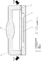
図1は本実施形態におけるレンズ一体型撮像ユニット1の断面図である。図1において、レンズ一体型撮像ユニット1は、レンズ固定部材3が基板7に固定された構造を有する。
FIG. 1 is a cross-sectional view of a lens-integrated
レンズ固定部材3は、レンズ2を固定する。レンズ固定部材3は筒状の形状をしている。ここで、筒状とは、中空で管状の形状をいい、円筒状のものの他、角柱状で中空のものや断面が楕円であって柱状の中空のものなどなども含む概念である。角柱状とは、三角柱や四角柱、六角柱等の形状をいう。
The
レンズ2はレンズ押さえ部材4によりレンズ固定部材3に固定される。レンズ押さえ部材4は、レンズ固定部材3に緩挿した上で、接着することにより、レンズ固定部材3に固定される。レンズ固定部材3は、絞り10を備える。
The
基板7は、撮像素子8を固定する素子固定部材である。基板7は、樹脂基板であってもよいし、セラミック基板であってもよい。基板7には凹部が形成されており、その中に撮像素子8が固定されている。撮像素子8は、CCDイメージセンサやCMOSセンサ等の撮像素子である。撮像素子8が固定された凹部は、全体がシールガラス6で覆われている。シールガラス6で凹部を覆うことにより、ほこりや湿気から撮像素子8を保護している。シールガラスの周りには、紫外線硬化型接着剤5でレンズ固定部材3が接着されている。つまり、レンズ固定部材3は、撮像素子8を囲むようにして基板7に紫外線硬化型接着剤5により固定されている。そのため、撮像素子8やシールガラス6は、少なくとも基板7、紫外線硬化型接着剤5、レンズ固定部材3およびレンズ2によって密閉される。ここで、密閉とは、少なくとも撮像素子8が存在する空間に、ほこりが混入することのない状態をいい、湿気が紫外線硬化型接着剤5を介して浸入する場合であっても、ほこりが入らない状態であれば密閉された状態といえる。
The
以上のように構成されたレンズ一体型撮像ユニット1の製造方法について、以下図2〜5を用いて説明する。図2は、レンズ一体型撮像ユニット1の製造工程を示すフローチャートである。
A method for manufacturing the lens-integrated
まず、レンズ2をレンズ固定部材3に取り付ける(S11、レンズ取付工程)。レンズ2をレンズ固定部材3に装着した状態で、レンズ押さえ部材4をレンズ固定部材3に緩挿し接着することにより、レンズ2をレンズ固定部材3に固定する。
First, the
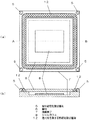
このレンズ取付工程S11とは別に、基板7を加工する。図3は、基板7に、撮像素子8、カバーガラス6および紫外線硬化型接着剤5を設けた際の、平面図および断面図である。図3(a)は平面図であり、図3(b)は図3(a)の線分ABにおける断面図である。まず、撮像素子8を基板7に実装する(S12、素子実装工程)。具体的には、撮像素子8を基板7に物理的に固定し、電気的に接続する。次に、撮像素子8を覆うようにシールガラス6を取り付ける(S13、シールガラス取付工程)。そして、紫外線硬化型接着剤5を塗布する(S14、接着剤塗布工程)。紫外線硬化型接着剤5の塗布位置は、基板7上の撮像素子8を囲むようにした位置である。つまり、基板7のレンズ固定部材3と対向する面上であって、撮影光束23の外側、すなわちシールガラス6より外側の全周である。紫外線硬化型接着剤5は、ディスペンサを用いて塗布するのが好ましい。
The
次に、レンズ固定部材3を基板7の紫外線硬化型接着剤5が塗布された部分に接着させる。このとき、レンズ2と撮像素子8との間の距離を調整する(S15、レンズ高さ調整工程)。この距離を調整するのは、レンズ2で集光された像のピントが撮像素子8上で合うようにするためである。このピントが合っていないと、レンズ一体型撮像ユニット1で撮像した画像のピントが合わなくなる。このピントは、レンズ2と撮像素子8との間の距離に依存する。そこで、画像のピントを合わせるために、レンズ2と撮像素子8との間の距離を調整するのである。レンズ高さ調整工程S15の詳細は後述する。
Next, the
次に、レンズ2と撮像素子8との間の距離を調整し、レンズ固定部材3および基板7を保持した状態で、紫外線硬化型接着剤5に紫外線を照射して硬化する(S16、接着剤硬化工程)。紫外線硬化型接着剤5の硬化は、レンズ固定部材3と基板7との隙間に充填された接着剤に対して、図1に示すように、レンズ一体型撮像ユニット1の側方の全方位から略水平方向に紫外線を照射することにより行われる。このようにして、レンズ一体型撮像ユニット1の組立は完了する。
Next, the distance between the
組み立てられたレンズ一体型撮像ユニット1は撮像装置に組み込まれることによって、画像を生成できる。例えば、赤外線カットフィルタを備えた外装部材内に収納すれば、外乱光の侵入を防止できる撮像装置を得ることができる。なお、撮像装置としては、デジタルスチルカメラ、デジタルビデオカメラ、カメラ付き携帯電話端末などが考えられる。
The assembled lens-integrated
次に、レンズ高さ調整工程S15について、図4、5を用いて説明する。図4は、この工程の詳細を示したフローチャートである。図5は、レンズ高さ調整工程S15における各部材の位置関係を説明するための断面図である。 Next, the lens height adjusting step S15 will be described with reference to FIGS. FIG. 4 is a flowchart showing details of this process. FIG. 5 is a cross-sectional view for explaining the positional relationship of each member in the lens height adjustment step S15.
レンズ高さ調整工程S15には、図5に示すように、組み立てられた基板7およびレンズ固定部材3のほかに、テーブル21、合焦調整チャート22、アーム23が必要である。テーブル21は、水平方向であるX軸/Y軸方向にそれぞれ移動可能なX軸テーブル21x、Y軸テーブル21yと鉛直方向であるZ軸方向に移動可能なZ軸テーブル21zとを組み合わせたものである。合焦調整チャート22は、所定のパターンが形成された幕である。アーム23は、レンズ固定部材3を所定の位置に保持しておくためのものである。なお、これらのテーブル21、合焦調整チャート22、アーム23は、レンズ一体型撮像ユニット1の製造装置として一体に構成してもよく、複数の製造装置として構成してもよい。
In the lens height adjustment step S15, as shown in FIG. 5, in addition to the assembled
まず、これらの部材を図5に示す位置関係となるように配置する(S151、部材セット工程)。すなわち、レンズ固定部材3の前方、すなわち鉛直上方に合焦調整チャート22を配置する。レンズ固定部材3はアーム23で保持する。このとき、合焦調整チャート22とレンズ2の前方端2aとが所定の距離(ここでは距離L)になるように、アーム23を調整して、配置する。次に、基板7をテーブル21上に固定し、レンズ固定部材3と紫外線硬化型接着剤5とが接触しないように配置する。
First, these members are arranged so as to have the positional relationship shown in FIG. 5 (S151, member setting step). That is, the focusing
次に、レンズ2を介して、撮像素子8上に集光された画像を電気的信号に変換して、画像データを生成する(S152、撮像画像生成工程)。そして、製造者またはレンズ一体型撮像ユニット1の製造装置が、生成された画像をチェックして、基板7の中心とレンズ2の光軸とが一致しているかどうかを判断する(S153、光軸判断工程)。そして、光軸が一致していないと判断すると、テーブル21のX,Y軸テーブル21x,yを調整して、光軸が一致するように、基板7を水平方向に移動する(S154、水平移動工程)。
Next, the image focused on the
次に、製造者またはレンズ一体型撮像ユニット1の製造装置が、生成された画像をチェックして、撮像画像のピントが合っているかどうかを判断する(S155、合焦判断工程)。そして、撮像画像のピントが合っていないと判断すると、テーブル21のZ軸テーブル21zを調整して、基板7をレンズ固定部材3に近付ける(S156、鉛直移動工程)。
Next, the manufacturer or the manufacturing apparatus of the lens-integrated
一方、光軸が一致し、かつ撮像画像のピントが合った場合には、その状態でテーブル21を保持し(S157、テーブル保持工程)、接着剤硬化工程S16に移行する。 On the other hand, if the optical axes match and the captured image is in focus, the table 21 is held in that state (S157, table holding step), and the process proceeds to the adhesive curing step S16.
ここで、撮像画像のピントが合った場合には、紫外線硬化型接着剤5が全塗布箇所でレンズ固定部材3に潰され、レンズ固定部材3と基板7との間は紫外線硬化型接着剤5が隙間なく充填され、基板7に固定されたシールガラス6および撮像素子8は外界から密閉される。逆に言えば、撮像画像のピントが合った状態で、レンズ固定部材3で潰されるように、紫外線硬化型接着剤5の塗布量を調整しておく。
Here, when the captured image is in focus, the ultraviolet
なお、上記の説明においては、水平移動工程S154の後に鉛直移動工程S156を行うとしたが、これには限らず、鉛直移動工程S156の後に水平移動工程S154を行ってもよい。また、水平移動工程S154と鉛直移動工程S156とを複数回繰り返して、徐々に、ピントと光軸とを合わせるようにしてもよい。 In the above description, the vertical movement step S156 is performed after the horizontal movement step S154. However, the present invention is not limited to this, and the horizontal movement step S154 may be performed after the vertical movement step S156. Alternatively, the horizontal movement step S154 and the vertical movement step S156 may be repeated a plurality of times to gradually adjust the focus and the optical axis.
以上のように、本発明の実施の形態1にかかるレンズ一体型撮像ユニット1は、撮像素子8を固定する基板7と、撮像素子8を囲むようにして基板7上に紫外線硬化型接着剤5により固定された、筒状のレンズ固定部材3と、レンズ固定部材3に固定されたレンズ2と、を備え、撮像素子8は、少なくとも基板7、紫外線硬化型接着剤5、レンズ固定部材3およびレンズ2によって密閉されることを特徴とするものである。この構成により、従来技術とは異なって、余分な部材を必要とすることなく、撮像素子8周囲の防塵性を確保できる。
As described above, the lens-integrated
これに対して、従来の技術では、接着剤間に隙間が生じるため、撮像素子8周囲の防塵性を確保できない。その理由は以下の通りである。従来技術では、多点ノズルを使用して接着剤154の塗布を行っているため、ノズル間に接着剤の隙間が生じやすい。塗布された接着剤154にレンズ138を押し付けることにより、ノズル間の接着剤の隙間は狭まることになるが、それにも限界がある。特に、ノズル間の間隔が長いと、接着剤の隙間を完全に塞ぐことは困難である。したがって、従来技術において、カバー162を単に取り付けないようにしただけでは、接着剤154の間の隙間からほこりがレンズ2内に混入することとなるから、従来技術では撮像素子8周囲の防塵性を確保できないのである。
On the other hand, according to the conventional technique, since a gap is generated between the adhesives, the dustproof property around the
(実施の形態2)
本発明の実施の形態2について、図6、7を用いて説明する。図6は、本実施形態における紫外線硬化型接着剤5および熱硬化型接着剤11を塗布した状態の基板7の平面図および断面図である。図6(a)は平面図であり、図6(b)は図6(a)の線分ABにおける断面図である。図7は、本発明の実施の形態2にかかるレンズ一体型撮像ユニット31の断面図である。
(Embodiment 2)
A second embodiment of the present invention will be described with reference to FIGS. FIG. 6 is a plan view and a cross-sectional view of the
本発明の実施の形態2と本発明の実施の形態1とは、接着剤の種類および塗布方法、ならびに接着剤の硬化方法が相違する。その他は、共通するため説明を省略する。 The second embodiment of the present invention is different from the first embodiment of the present invention in the type and application method of the adhesive and the curing method of the adhesive. Since others are common, explanation is omitted.
図6において、撮像素子8を囲むようにして、接着剤5、11を塗布する。接着剤5は、紫外線を照射することにより硬化する紫外線硬化型接着剤5である。接着剤11は、加熱することにより硬化する熱硬化型接着剤11である。接着剤5、11の塗布は、まず紫外線硬化型接着剤5を基板7の四隅に、ディスペンサを用いて塗布し、その後別のディスペンサを用いて熱硬化型接着剤11を線状に塗布する。この際、熱硬化型接着剤11は、紫外線硬化型接着剤5に接するように、隙間なく塗布する。
In FIG. 6,
このように、紫外線硬化型接着剤5を四隅に塗布した後に、熱硬化型接着剤11を線状に塗布することにより、熱硬化型接着剤5の塗布長さを調節することができるので、両接着剤の間に隙間が発生するのを防ぐことができる。しかし、塗布の順番はこれに限らず、熱硬化型接着剤11を線状に塗布した後に、紫外線硬化型接着剤5を点状に塗布してもよい。
Thus, the application length of the
接着剤5、11を塗布した後、本発明の実施の形態1と同様に、レンズ高さ調整工程S15を経て、接着剤5、11を硬化させる。このときの接着剤5、11を硬化させる工程について説明する。
After the
まず、レンズ一体型撮像ユニット31のレンズ固定部材3と基板7との隙間に充填された接着剤5、11に対して、レンズ一体型撮像ユニット31の側方の全方位から略水平方向に紫外線を照射する。これにより、レンズ固定部材3と基板7との接着について、最低限の接着強度を確保する。この後、このレンズ一体型撮像ユニット31を熱硬化炉に入れ、熱硬化型接着剤11を加熱硬化させる。これにより、レンズ一体型撮像ユニット31の組立は完了する。
First, with respect to the
以上のように、本発明の実施の形態2によれば、紫外線硬化型接着剤5および熱硬化型接着剤11を塗布することにより、熱硬化型接着剤11の接着力により、接着強度を補強できるので、紫外線硬化型接着剤5の塗布量を少なくすることができる。そうすると、紫外線硬化型接着剤5の硬化時間は短くすることができる。紫外線硬化型接着剤5を硬化する間は、レンズ一体型撮像ユニット31を保持しておく必要があり、保持装置(レンズ一体型撮像ユニット31の製造装置)を占有してしまうことになるが、この1個当たりの占有時間を短くできるので、レンズ一体型撮像ユニット31の生産効率を上げることができる。なお、本発明の実施の形態2によれば、紫外線硬化工程とは別に熱硬化工程が必要となるが、熱硬化工程においては、レンズ一体型撮像ユニット31を複数台まとめてオフラインとして熱硬化炉に入れれば良いため、生産性を下げることはない。
As described above, according to
(実施の形態3)
本発明の実施の形態3にかかるレンズ一体型撮像ユニットについて、図8を用いて説明する。図8は、本実施形態における紫外線硬化型接着剤5および熱硬化型接着剤12を塗布した状態の基板7の平面図および断面図である。図8(a)は平面図であり、図8(b)は図8(a)の線分ABにおける断面図である。
(Embodiment 3)
A lens-integrated imaging unit according to
本発明の実施の形態3と本発明の実施の形態2とは、接着剤の種類および塗布方法が相違する。その他は、共通するため説明を省略する。 The third embodiment of the present invention is different from the second embodiment of the present invention in the type of adhesive and the coating method. Since others are common, description is abbreviate | omitted.
図8において、撮像素子8を囲むようにして、接着剤5、12を塗布する。接着剤5は、紫外線を照射することにより硬化する紫外線硬化型接着剤5である。接着剤12は、加熱することにより硬化する熱硬化型接着剤12であって、遮光性を有するものである。熱硬化型接着剤に遮光性を持たせる手段としては、例えば、黒色の顔料、染料、カーボン等を含有させるなどの手段がある。接着剤5、12の塗布は、まず紫外線硬化型接着剤5を基板7の3箇所に、ディスペンサを用いて塗布し、その後別のディスペンサを用いて熱硬化型接着剤12を線状に塗布する。ここで、紫外線硬化型接着剤5の塗布箇所は、塗布箇所の中心が基板7、あるいは、レンズ2とレンズ押さえ部材4を装着したレンズ固定部材3の重心になるべく一致するような箇所にする。また、熱硬化型接着剤12は、撮像素子8の周囲を隙間なく塗布する。
In FIG. 8,
接着剤5、12を塗布した後、本発明の実施の形態2と同様に、レンズ高さ調整工程S15を経て、紫外線硬化および熱硬化を行い、レンズ一体型撮像ユニットの組立を完了する。
After applying the
以上のように、本発明の実施の形態3によれば、レンズ固定部材3と基板7との間の隙間に遮光性を有する熱硬化型接着剤12を充填したため、この隙間から外光が侵入することを防ぐことができる。
As described above, according to the third embodiment of the present invention, the gap between the
また、本発明の実施の形態3によれば、紫外線硬化型接着剤5の塗布点数を3箇所にして塗布量を少なくしたため、より紫外線硬化時間を短くすることができる。また、紫外線硬化型接着剤5の塗布箇所の中心と基板7、あるいは、レンズ2とレンズ押さえ部材4を装着したレンズ固定部材3の重心とを一致させたため、少ない塗布量であっても、基板7をバランスよく保持することができるため、熱硬化前に基板7がレンズ固定部材3から離脱するなどの不具合を防止できる。
Further, according to
(実施の形態4)
以上のように、本発明の実施の形態として、実施の形態1〜3について説明したが、本発明は、他の実施の形態により実現してもよい。ここでは、他の実施の形態をまとめて、実施の形態4として以下、説明する。
(Embodiment 4)
As mentioned above, although Embodiment 1-3 was demonstrated as embodiment of this invention, you may implement | achieve this invention by other embodiment. Here, other embodiments are collectively described as
本発明の実施の形態1〜3では、レンズ2をレンズ固定部材3に装着し、レンズ押さえ部材4をレンズ固定部材3に緩挿、接着することにより、レンズ2をレンズ固定部材3に固定するとしたが、これに限らない。例えば、レンズ押さえ部材4を用いず、レンズ固定部材3について熱かしめをしてレンズ2を固定するようにしてもよく、また、レンズ2をレンズ固定部材3に接着剤で固定するようにしてもよい。
In
また、本発明の実施の形態1〜3では、レンズ2をレンズ固定部材3に固定するとしたが、これらを一体に形成してもよい。その実施例におけるレンズ一体型撮像ユニット41の断面図を図9に示す。図9において、レンズ13は、レンズ固定部材も兼ねており、基板7に直接固定されている。このような構成によれば、レンズ13は透明部材であり、紫外線の透過率が高いため、紫外線硬化時に、図9に示すように基板7の上方から照射することもできる。そのため、紫外線の照射角度を厳密に管理する必要がなく、仮に、照射角度が多少ずれたとしても、紫外線硬化型接着剤5が硬化しないといった不具合を防ぐことができる。ただし、紫外線は、略水平方向から照射してもよい。
Moreover, in Embodiment 1-3 of this invention, although the
また、レンズ2とレンズ固定部材3とを一体に形成した場合、レンズ13の表面に黒色コート膜14を形成してもよい。このときの実施例におけるレンズ一体型撮像ユニット51の断面図を図10に示す。黒色コート膜14は、撮影光束の通る光学有効径よりも外側に形成する。このように、レンズ13の光学有効径の外側に黒色コート膜14を形成することにより、撮像素子8に外乱光が照射するのを防止できる。なお、黒色コート膜14は、塗料、インク、蒸着膜のような所定の遮光性を有するものであれば良い。また、黒色コート膜14は、レンズ13の表面に形成してもよく、内壁に形成してもよい。また、黒色コート膜14を形成する場合には、充填材も遮光性を有する熱硬化型接着剤12を用いるのが好ましい。ユニット51内の遮光性を高めるためのである。但し、遮光性を有する熱硬化型接着剤12を塗布しただけでは、紫外線硬化をすることができず、生産性が悪くなるため、図8に示すように、遮光性を有する熱硬化型接着剤12に加えて、紫外線硬化型接着剤5も併用するのが好ましい。
Further, when the
また、本発明の実施の形態1〜3では、レンズ固定部材3と基板7との間の隙間に、接着剤5、11、12を充填するとしたが、これに限らず、レンズ2と撮像素子8との距離を維持し、防塵性を確保できるものであれば、他の充填剤を充填してもよい。例えば、粘着性のある充填剤を充填するようにしてもよい。
In the first to third embodiments of the present invention, the gaps between the
また、本発明の実施の形態3では、紫外線硬化型接着剤5を3点塗布するとしたが、4点以上でも良い。例えば、図11に紫外線硬化型接着剤5を4点塗布する場合の塗布の状態を示す。3点塗布に比べると、紫外線9の照射エネルギーは増えるが、紫外線硬化型接着剤5を基板7の四隅に塗布できるため、熱硬化型接着剤12の塗布が、紫外線硬化型接着剤5を迂回する量を最小限に抑えることができ、塗布作業を容易に行うことができる。また、塗布箇所の中心と基板7、あるいは、レンズ2とレンズ押さえ部材4を装着したレンズ固定部材3の重心とを容易に一致させることができる。
In the third embodiment of the present invention, three points of the ultraviolet
また、本発明の実施の形態3では、熱硬化型接着剤12の塗布位置を紫外線硬化型接着剤5の内周側としたが、逆に、紫外線硬化型接着剤5の外周側に熱硬化型接着剤12を塗布してもよい。この場合、予め基板7に塗布した紫外線硬化型接着剤5をレンズ2と撮像素子8との距離を所定距離に保持した状態で紫外線照射により硬化させ、この後、紫外線硬化型接着剤5の外周側に熱硬化型接着剤12を塗布し、熱硬化炉に入れ、熱硬化型接着剤12を硬化させることにより、レンズ一体型撮像ユニット61を完成させることができる。
In
また、本発明の実施の形態1〜3では、レンズ2を一枚の構成にしたが、これには限らない。例えば、3枚構成でもよく、さらに多くのレンズで構成してもよい。また、レンズの種類は、凸レンズでもよく凹レンズでもよく、球面レンズでもよく、非球面レンズでもよい。さらに、レンズ2の材料もガラスでもよく、プラスチックでもよい。
In the first to third embodiments of the present invention, the
また、本発明の実施の形態1〜3では、レンズ固定部材3を1つの部材で構成するとしたが、これに限らず、複数の部材からなる構成としてもよい。例えば、図12に示す構成としてもよい。図12は、この例におけるレンズ一体型撮像ユニット61の断面図である。この実施例における回転部材63と接続部材64とを組み合わせた構成は、本発明のレンズ固定部材の一例である。基板7には、接続部材64を紫外線硬化型接着剤5で接着して固定する。そして、接続部材64は回転部材63を保持する。接続部材64と回転部材63とは、緩く嵌め合うようにして組み合わされている。組み合わされた状態で、回転部材63に設けられたカバー部68、69が接続部材64を覆うように構成されている。この構成により、回転部材63と接続部材64との間に隙間が生じることはなく、撮像素子8およびシールガラス6が存在する空間は密閉された状態に保たれる。回転部材63は、接続部材64の周りを回転可能である。なお、接続部材64の外周にはカム溝66が斜めに形成されており、回転部材63にはカム溝66とかみ合うカムピン65が形成されている。そのため、回転部材63が接続部材64の周りを回転すると、回転部材63はその回転に伴って、図12における鉛直方向に移動することとなる。回転部材63が鉛直方向に移動すると、撮像素子8とレンズ2との間の距離が変わる。この動作を利用して、レンズ一体型撮像ユニット61は通常撮影とマクロ撮影とを切り換えることができる。
In the first to third embodiments of the present invention, the
本発明にかかるレンズ一体型撮像ユニットは、ほこりによって生じる画像のゴミを防止できるので、デジタルスチルカメラ、デジタルビデオカメラ、カメラ付き携帯電話端末、内視鏡、ロボットの目などに適用可能である。 Since the lens-integrated image pickup unit according to the present invention can prevent dust from being generated due to dust, it can be applied to digital still cameras, digital video cameras, mobile phone terminals with cameras, endoscopes, robot eyes, and the like.
1、31、41、51、61 レンズ一体型撮像ユニット
2、13 レンズ
3 レンズ固定部材
4 レンズ押さえ部材
5 紫外線硬化型接着剤
6 シールガラス
7 基板
8 撮像素子
10 絞り
11、12 熱硬化型接着剤
14 黒色コート膜
DESCRIPTION OF
Claims (9)
前記撮像素子を囲むようにして前記素子固定部材上に充填剤により固定された、筒状のレンズ固定部材と、
前記レンズ固定部材に固定されたレンズと、を備え、
前記撮像素子は、少なくとも前記素子固定部材、前記充填剤、前記レンズ固定部材および前記レンズによって密閉されることを特徴とするレンズ一体型撮像ユニット。 An element fixing member for fixing the imaging element;
A cylindrical lens fixing member fixed by a filler on the element fixing member so as to surround the imaging element;
A lens fixed to the lens fixing member,
The lens-integrated imaging unit, wherein the imaging element is sealed by at least the element fixing member, the filler, the lens fixing member, and the lens.
前記シールガラスは、少なくとも前記素子固定部材、前記充填剤、前記レンズ固定部材および前記レンズによって密閉されることを特徴とする請求項1に記載のレンズ一体型撮像ユニット。 A seal glass for protecting the surface of the image sensor;
The lens-integrated imaging unit according to claim 1, wherein the seal glass is sealed by at least the element fixing member, the filler, the lens fixing member, and the lens.
撮像素子を基板に固定する素子実装工程と、
前記固定された撮像素子の全周に渡って隙間なく、前記基板の上に接着剤を塗布する塗布工程と、
前記レンズを介して前記撮像素子に集光される画像のピントを合わせるように、前記レンズと前記撮像素子との距離を調整するレンズ高さ調整工程と、
前記レンズと前記撮像素子との距離を、前記レンズ高さ調整工程で調整された距離に保ちつつ、前記接着剤を硬化する接着剤硬化工程と、
を備えるレンズ一体型撮像ユニットの製造方法。 A lens fixing step of fixing the lens to the lens fixing member;
An element mounting process for fixing the image sensor to the substrate;
An application step of applying an adhesive on the substrate without a gap over the entire circumference of the fixed imaging device;
A lens height adjustment step of adjusting a distance between the lens and the image sensor so as to focus an image condensed on the image sensor via the lens;
An adhesive curing step of curing the adhesive while maintaining the distance between the lens and the imaging element at the distance adjusted in the lens height adjustment step;
A method of manufacturing a lens-integrated image pickup unit.
Priority Applications (1)
| Application Number | Priority Date | Filing Date | Title |
|---|---|---|---|
| JP2004310495A JP2006128755A (en) | 2004-10-26 | 2004-10-26 | Lens-integrated imaging unit and imaging apparatus provided therewith |
Applications Claiming Priority (1)
| Application Number | Priority Date | Filing Date | Title |
|---|---|---|---|
| JP2004310495A JP2006128755A (en) | 2004-10-26 | 2004-10-26 | Lens-integrated imaging unit and imaging apparatus provided therewith |
Publications (2)
| Publication Number | Publication Date |
|---|---|
| JP2006128755A true JP2006128755A (en) | 2006-05-18 |
| JP2006128755A5 JP2006128755A5 (en) | 2007-12-06 |
Family
ID=36723010
Family Applications (1)
| Application Number | Title | Priority Date | Filing Date |
|---|---|---|---|
| JP2004310495A Pending JP2006128755A (en) | 2004-10-26 | 2004-10-26 | Lens-integrated imaging unit and imaging apparatus provided therewith |
Country Status (1)
| Country | Link |
|---|---|
| JP (1) | JP2006128755A (en) |
Cited By (10)
| Publication number | Priority date | Publication date | Assignee | Title |
|---|---|---|---|---|
| WO2009052793A1 (en) * | 2007-10-27 | 2009-04-30 | Adc Automotive Distance Control Systems Gmbh | Method and device for assembling and adjusting an image recording unit |
| JP2010016744A (en) * | 2008-07-07 | 2010-01-21 | Konica Minolta Opto Inc | Image capturing apparatus and mobile terminal |
| US20100038017A1 (en) * | 2008-08-14 | 2010-02-18 | Oki Semiconductor Co., Ltd. | Camera module and method of manufacturing camera module |
| JP2010141865A (en) * | 2008-12-10 | 2010-06-24 | Optopac Co Ltd | Image sensor camera module and method of manufacturing same |
| JP2010263606A (en) * | 2009-04-10 | 2010-11-18 | Ricoh Co Ltd | Imaging device, on-vehicle imaging device, and method and device of manufacturing imaging device |
| JP2011209417A (en) * | 2010-03-29 | 2011-10-20 | Ricoh Co Ltd | Imaging apparatus |
| US8064146B2 (en) | 2006-07-28 | 2011-11-22 | Sony Corporation | Image pickup apparatus |
| JP2011244346A (en) * | 2010-05-20 | 2011-12-01 | Toshiba Corp | Camera module |
| US10714518B2 (en) | 2017-12-18 | 2020-07-14 | Shinko Electric Industries Co., Ltd. | Imaging device |
| JP2020160142A (en) * | 2019-03-25 | 2020-10-01 | 京セラ株式会社 | Imaging apparatus, on-vehicle camera, vehicle, and method for manufacturing imaging apparatus |
Citations (8)
| Publication number | Priority date | Publication date | Assignee | Title |
|---|---|---|---|---|
| JPS6069621A (en) * | 1983-09-26 | 1985-04-20 | Olympus Optical Co Ltd | Endoscope |
| JPS61134187A (en) * | 1984-12-04 | 1986-06-21 | Toshiba Corp | Solid-state image pickup device |
| JPH02235035A (en) * | 1989-03-08 | 1990-09-18 | Olympus Optical Co Ltd | Camera |
| JPH03112050A (en) * | 1989-09-27 | 1991-05-13 | Toshiba Lighting & Technol Corp | Connecting method for reflecting mirror and lamp |
| JPH11109203A (en) * | 1997-10-01 | 1999-04-23 | Asahi Optical Co Ltd | Digital still camera |
| JPH11345955A (en) * | 1998-05-29 | 1999-12-14 | Sony Corp | Integrated lens solid-state image sensor and method and device for mounting lens thereof |
| JP2003046825A (en) * | 2001-01-12 | 2003-02-14 | Konica Corp | Imaging apparatus and imaging lens |
| JP2003214432A (en) * | 2002-01-24 | 2003-07-30 | Matsushita Electric Ind Co Ltd | Bearing device and its sealing method |
-
2004
- 2004-10-26 JP JP2004310495A patent/JP2006128755A/en active Pending
Patent Citations (8)
| Publication number | Priority date | Publication date | Assignee | Title |
|---|---|---|---|---|
| JPS6069621A (en) * | 1983-09-26 | 1985-04-20 | Olympus Optical Co Ltd | Endoscope |
| JPS61134187A (en) * | 1984-12-04 | 1986-06-21 | Toshiba Corp | Solid-state image pickup device |
| JPH02235035A (en) * | 1989-03-08 | 1990-09-18 | Olympus Optical Co Ltd | Camera |
| JPH03112050A (en) * | 1989-09-27 | 1991-05-13 | Toshiba Lighting & Technol Corp | Connecting method for reflecting mirror and lamp |
| JPH11109203A (en) * | 1997-10-01 | 1999-04-23 | Asahi Optical Co Ltd | Digital still camera |
| JPH11345955A (en) * | 1998-05-29 | 1999-12-14 | Sony Corp | Integrated lens solid-state image sensor and method and device for mounting lens thereof |
| JP2003046825A (en) * | 2001-01-12 | 2003-02-14 | Konica Corp | Imaging apparatus and imaging lens |
| JP2003214432A (en) * | 2002-01-24 | 2003-07-30 | Matsushita Electric Ind Co Ltd | Bearing device and its sealing method |
Cited By (15)
| Publication number | Priority date | Publication date | Assignee | Title |
|---|---|---|---|---|
| US8064146B2 (en) | 2006-07-28 | 2011-11-22 | Sony Corporation | Image pickup apparatus |
| WO2009052793A1 (en) * | 2007-10-27 | 2009-04-30 | Adc Automotive Distance Control Systems Gmbh | Method and device for assembling and adjusting an image recording unit |
| DE112008001917B4 (en) | 2007-10-27 | 2021-09-23 | Adc Automotive Distance Control Systems Gmbh | Method and device for assembling and adjusting an image pickup unit |
| JP2010016744A (en) * | 2008-07-07 | 2010-01-21 | Konica Minolta Opto Inc | Image capturing apparatus and mobile terminal |
| US8202391B2 (en) * | 2008-08-14 | 2012-06-19 | Oki Semiconductor Co., Ltd. | Camera module and method of manufacturing camera module |
| US20100038017A1 (en) * | 2008-08-14 | 2010-02-18 | Oki Semiconductor Co., Ltd. | Camera module and method of manufacturing camera module |
| JP2010045650A (en) * | 2008-08-14 | 2010-02-25 | Oki Semiconductor Co Ltd | Camera module and method for manufacturing camera module |
| JP2010141865A (en) * | 2008-12-10 | 2010-06-24 | Optopac Co Ltd | Image sensor camera module and method of manufacturing same |
| US8063982B2 (en) | 2008-12-10 | 2011-11-22 | Optopac Co., Ltd. | Image sensor camera module including a protruding portion and method of manufacturing the same |
| JP2010263606A (en) * | 2009-04-10 | 2010-11-18 | Ricoh Co Ltd | Imaging device, on-vehicle imaging device, and method and device of manufacturing imaging device |
| JP2011209417A (en) * | 2010-03-29 | 2011-10-20 | Ricoh Co Ltd | Imaging apparatus |
| JP2011244346A (en) * | 2010-05-20 | 2011-12-01 | Toshiba Corp | Camera module |
| US10714518B2 (en) | 2017-12-18 | 2020-07-14 | Shinko Electric Industries Co., Ltd. | Imaging device |
| JP2020160142A (en) * | 2019-03-25 | 2020-10-01 | 京セラ株式会社 | Imaging apparatus, on-vehicle camera, vehicle, and method for manufacturing imaging apparatus |
| JP7325202B2 (en) | 2019-03-25 | 2023-08-14 | 京セラ株式会社 | Imaging device manufacturing method and imaging device |
Similar Documents
| Publication | Publication Date | Title |
|---|---|---|
| JP4096588B2 (en) | Imaging device | |
| TWI667525B (en) | Camera module and assembly method thereof | |
| JP6953454B2 (en) | Fixed focus camera module and its focus adjustment device and focus adjustment method | |
| JP5771901B2 (en) | Imaging device | |
| KR101455124B1 (en) | Image pickup apparatus having imaging sensor package | |
| CN109581785B (en) | Camera module for reducing stray light and photosensitive assembly thereof | |
| JP2012114675A (en) | Imaging apparatus | |
| JP7205486B2 (en) | Imaging device | |
| KR20060034687A (en) | Imaging device, portable terminal using the same, and image device producing method | |
| KR20140076329A (en) | Camera module | |
| JP2006128755A (en) | Lens-integrated imaging unit and imaging apparatus provided therewith | |
| JP4248586B2 (en) | IMAGING DEVICE, MANUFACTURING METHOD THEREOF, AND PORTABLE INFORMATION TERMINAL AND IMAGING DEVICE WITH THE IMAGING DEVICE | |
| JP2018005178A (en) | Lens-holding mechanism and image capturing device | |
| JPWO2016084394A1 (en) | Imaging device | |
| JP2006018253A (en) | Optical member and its manufacturing method | |
| KR20150030906A (en) | Camera module | |
| WO2019198318A1 (en) | Imaging device, electronic apparatus, and method for manufacturing imaging device | |
| JP4696192B2 (en) | Solid-state image pickup device unit, manufacturing method thereof, and image pickup apparatus | |
| JP2008233271A (en) | Lens unit, lens module, camera module, and method for manufacturing lens unit | |
| US9432560B2 (en) | Image capturing module for saving focusing time and increasing assembly flatness and method of assembling the same | |
| KR101589499B1 (en) | Method for setting position of imaging device | |
| JP5093324B2 (en) | Solid-state image pickup device unit, manufacturing method thereof, and image pickup apparatus | |
| JPWO2019111575A1 (en) | Imaging device and manufacturing method of imaging device | |
| JP4492085B2 (en) | Imaging device and portable terminal | |
| JP2010205770A (en) | Imaging device |
Legal Events
| Date | Code | Title | Description |
|---|---|---|---|
| A521 | Request for written amendment filed |
Free format text: JAPANESE INTERMEDIATE CODE: A523 Effective date: 20071019 |
|
| A621 | Written request for application examination |
Free format text: JAPANESE INTERMEDIATE CODE: A621 Effective date: 20071019 |
|
| RD01 | Notification of change of attorney |
Free format text: JAPANESE INTERMEDIATE CODE: A7421 Effective date: 20071113 |
|
| RD01 | Notification of change of attorney |
Free format text: JAPANESE INTERMEDIATE CODE: A7421 Effective date: 20091120 |
|
| A977 | Report on retrieval |
Free format text: JAPANESE INTERMEDIATE CODE: A971007 Effective date: 20091201 |
|
| A131 | Notification of reasons for refusal |
Free format text: JAPANESE INTERMEDIATE CODE: A131 Effective date: 20100119 |
|
| A02 | Decision of refusal |
Free format text: JAPANESE INTERMEDIATE CODE: A02 Effective date: 20100518 |