JP2006098403A - Sensor system and operating method thereof - Google Patents
Sensor system and operating method thereof Download PDFInfo
- Publication number
- JP2006098403A JP2006098403A JP2005279269A JP2005279269A JP2006098403A JP 2006098403 A JP2006098403 A JP 2006098403A JP 2005279269 A JP2005279269 A JP 2005279269A JP 2005279269 A JP2005279269 A JP 2005279269A JP 2006098403 A JP2006098403 A JP 2006098403A
- Authority
- JP
- Japan
- Prior art keywords
- sensor
- conductive elements
- operable
- probe
- output signal
- Prior art date
- Legal status (The legal status is an assumption and is not a legal conclusion. Google has not performed a legal analysis and makes no representation as to the accuracy of the status listed.)
- Pending
Links
Images
Classifications
-
- G—PHYSICS
- G01—MEASURING; TESTING
- G01D—MEASURING NOT SPECIALLY ADAPTED FOR A SPECIFIC VARIABLE; ARRANGEMENTS FOR MEASURING TWO OR MORE VARIABLES NOT COVERED IN A SINGLE OTHER SUBCLASS; TARIFF METERING APPARATUS; MEASURING OR TESTING NOT OTHERWISE PROVIDED FOR
- G01D5/00—Mechanical means for transferring the output of a sensing member; Means for converting the output of a sensing member to another variable where the form or nature of the sensing member does not constrain the means for converting; Transducers not specially adapted for a specific variable
- G01D5/12—Mechanical means for transferring the output of a sensing member; Means for converting the output of a sensing member to another variable where the form or nature of the sensing member does not constrain the means for converting; Transducers not specially adapted for a specific variable using electric or magnetic means
- G01D5/14—Mechanical means for transferring the output of a sensing member; Means for converting the output of a sensing member to another variable where the form or nature of the sensing member does not constrain the means for converting; Transducers not specially adapted for a specific variable using electric or magnetic means influencing the magnitude of a current or voltage
- G01D5/24—Mechanical means for transferring the output of a sensing member; Means for converting the output of a sensing member to another variable where the form or nature of the sensing member does not constrain the means for converting; Transducers not specially adapted for a specific variable using electric or magnetic means influencing the magnitude of a current or voltage by varying capacitance
- G01D5/241—Mechanical means for transferring the output of a sensing member; Means for converting the output of a sensing member to another variable where the form or nature of the sensing member does not constrain the means for converting; Transducers not specially adapted for a specific variable using electric or magnetic means influencing the magnitude of a current or voltage by varying capacitance by relative movement of capacitor electrodes
- G01D5/2417—Mechanical means for transferring the output of a sensing member; Means for converting the output of a sensing member to another variable where the form or nature of the sensing member does not constrain the means for converting; Transducers not specially adapted for a specific variable using electric or magnetic means influencing the magnitude of a current or voltage by varying capacitance by relative movement of capacitor electrodes by varying separation
-
- G—PHYSICS
- G01—MEASURING; TESTING
- G01B—MEASURING LENGTH, THICKNESS OR SIMILAR LINEAR DIMENSIONS; MEASURING ANGLES; MEASURING AREAS; MEASURING IRREGULARITIES OF SURFACES OR CONTOURS
- G01B7/00—Measuring arrangements characterised by the use of electric or magnetic techniques
- G01B7/14—Measuring arrangements characterised by the use of electric or magnetic techniques for measuring distance or clearance between spaced objects or spaced apertures
Abstract
Description
本発明は、一般的にセンサシステムに関し、より詳細には、センサの出力に応じてセンサの物理特性を調整するように動作可能なセンサシステムに関する。 The present invention relates generally to sensor systems, and more particularly to a sensor system operable to adjust the physical characteristics of a sensor in response to the output of the sensor.
2物体間の距離を測定するために、センサの様々な型が使用されている。その上、これらのセンサは、様々な用途で使用されている。例えば、タービンは、シュラウドに隣接して配置されたタービン羽根を有する。タービン羽根とシュラウドの間の隙間は、タービン羽根の温度に依存して変化する。例えば、シュラウドとタービン羽根の間の隙間はタービンが冷たいとき最も大きく、タービンが熱くなるにつれて徐々に減少する。タービン羽根とシュラウドの間のギャップすなわち隙間は、タービンの安全で効率的な動作のために維持されることが望ましい。タービン羽根とシュラウドの間の距離を測定するようにセンサをタービン内に配置することができる。この距離は、シュラウドとタービン羽根の間の所望の変位を維持するようにシュラウドの動きを導くために使用することができる。 Various types of sensors are used to measure the distance between two objects. In addition, these sensors are used in a variety of applications. For example, the turbine has turbine blades disposed adjacent to the shroud. The clearance between the turbine blade and the shroud varies depending on the temperature of the turbine blade. For example, the clearance between the shroud and the turbine blades is greatest when the turbine is cold and gradually decreases as the turbine heats up. The gap between the turbine blades and the shroud is desirably maintained for safe and efficient operation of the turbine. Sensors can be placed in the turbine to measure the distance between the turbine blades and the shroud. This distance can be used to guide the movement of the shroud to maintain the desired displacement between the shroud and the turbine blades.
ある特定の用途では、2物体間の距離を測定するために、キャパシタンスプローブが使用される。従来、キャパシタンスプローブ先端の寸法は、2物体間の単一変位距離に対応するように選ばれている。小さなプローブは、一般に、信号対雑音比のために小さな距離の測定に制限される。同様に、大きなプローブは、一般に、小さな距離の測定では2物体間の距離の分解能が悪いので、大きな距離の測定に制限される。その結果として、従来のキャパシタンスプローブは、プローブ先端がそのために設計された変位距離以外の変位距離では不正確であることがある。
したがって、互いに変位する2物体間の隙間を変位の全範囲にわたって正確に測定するセンサシステムを実現する必要がある。 Therefore, it is necessary to realize a sensor system that accurately measures the gap between two objects that are displaced from each other over the entire range of displacement.
簡単に言うと、本発明の一態様に従って、センサシステムが提供される。このセンサシステムは、感知されたパラメータを表す出力信号を供給するように動作可能なセンサを備える。また、センサシステムはセンサに結合された制御システムを備え、この制御システムは、感知されたパラメータを表す出力信号に基づいてセンサの物理特性を変えるように動作可能である。 Briefly, in accordance with one aspect of the present invention, a sensor system is provided. The sensor system includes a sensor operable to provide an output signal representative of the sensed parameter. The sensor system also includes a control system coupled to the sensor that is operable to change the physical characteristics of the sensor based on an output signal representative of the sensed parameter.
本発明の他の態様に従って、センサシステムを動作させる方法が提供される。この方法は、センサによって感知されたパラメータを表す出力信号を受け取ること、および感知されたパラメータを表す出力信号に基づいてセンサの物理特性を制御することを備える。 In accordance with another aspect of the present invention, a method for operating a sensor system is provided. The method comprises receiving an output signal representative of a parameter sensed by the sensor and controlling a physical characteristic of the sensor based on the output signal representative of the sensed parameter.
本発明のこれらおよび他の特徴、態様、および有利点は、添付の図面を参照して次の詳細な説明を読むとき、より適切に理解されるようになるだろう。この図面では、図面全体を通して、同様な符合は同様な部分を表す。 These and other features, aspects and advantages of the present invention will become better understood when the following detailed description is read with reference to the accompanying drawings. In the drawings, like numerals refer to like parts throughout the drawings.
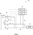
ここで図1を参照すると、センサシステムが与えられ、全体的に参照数字10で表されている。このセンサシステム10は、感知されたパラメータを表す出力信号を供給するように動作可能なプローブ12を備える。プローブ12は、第1の導電要素14、第2の導電要素16、および第3の導電要素18を備える。しかし、もっと少ない数またはもっと多い数の導電要素をセンサシステム10で使用することができる。その上、センサシステム10の図示の実施形態は、導電要素14、16および18をプローブ制御システム20に選択的に結合するために、プローブ制御システム20、第1のスイッチ22、第2のスイッチ24、および第3のスイッチ26を備える。以下でより詳細に説明するように、プローブ制御システム20は、導電要素14、16および18を互いに選択的に結合することによって、プローブ12の出力に基づいてプローブ12の構成を最適化するように動作可能である。導電要素14、16および18は、また、間隔制御システム28にも結合されており、この間隔制御システム28は、プローブ12と、また以下で詳細に説明する対象との間の間隔を制御するように動作可能である。追加の導電要素30が、戻り経路として作用しかつプローブ12を雑音および干渉から遮蔽するように設けられる。しかし、プローブ12を遮蔽するために、より多い数の導電要素を導電要素30に結合することができる。さらに、導電要素14、16および18は、ケーブル32および34を介してそれぞれ間隔制御システム28およびプローブ制御システム20に結合される。
Referring now to FIG. 1, a sensor system is provided and is generally designated by the
図示の実施形態では、プローブ12は、プローブ12と物体36の間のキャパシタンスを感知するキャパシタンスプローブである。2物体間のキャパシタンスは、プローブ12と物体36の間の重なり表面積(A)および間隔(S)38の関数である。センサシステム10では、物体36の面積はプローブ12の面積よりも大きいので、重なり表面積(A)はプローブ12の面積である。2枚の平行板間のキャパシタンスは、次式で与えられる。
In the illustrated embodiment,
C=εA/S (1)
ここで、Cはキャパシタンス、
εは平行板間の媒体の誘電率、
Aは平行板間の重なり面積、そして、
Sは平行板の隔たりである。
C = εA / S (1)
Where C is the capacitance,
ε is the dielectric constant of the medium between parallel plates,
A is the overlapping area between parallel plates, and
S is the distance between the parallel plates.
キャパシタンス(C)を感知することによって、プローブ12で、プローブ12と物体36の間の間隔(S)38を定めることができるようになる。上の式(1)を操作することで、次式によって、間隔(S)はキャパシタンス(C)に関係付けられる。
By sensing the capacitance (C), the
S=εA/C (2)
以下でより詳細に議論するように、間隔制御システム28は、プローブ12から受け取られるキャパシタンス(C)を表す信号に基づいて、プローブ12と物体36の間の間隔(S)38を制御するように動作可能である。この実施形態では、間隔制御システム28は、上の式(2)および間隔制御システム28にプログラムされたデータを使用して、プローブ12と物体36の間の間隔(S)38を定めるように動作可能である。しかし、間隔制御システム28はただ単にキャパシタンス(C)を使用して、プローブ12と物体36の間の間隔(S)38を制御することができる。キャパシタンス(C)および/または間隔(S)は、キャパシタンスおよび/または間隔(S)の所望の値と比較される。この実施形態では、間隔制御システム28は、所望のキャパシタンス(C)または間隔(S)を維持するように物体36の変位を導くように動作可能である。
S = εA / C (2)
As discussed in more detail below, the
プローブ制御システム20は、実際の間隔(S)38またはキャパシタンス(C)に対応するようにプローブ12の面積(A)を最適化するように動作可能である。プローブ制御システム20は、間隔(S)38が減少するにつれてプローブ12の面積(A)を減少させ、そして間隔(S)38が増加するにつれてプローブ12の面積(A)を増大させる。プローブ制御システム20は、スイッチ22、24および26を選択的に閉じ、それによって、間隔制御システム28に結合される特定の導電要素14、16および18を制御して、プローブ12の面積(A)を制御する。例えば、プローブ12と物体36の間の間隔(S)38が小さい場合には、プローブ制御システム20は、スイッチ26を閉じかつスイッチ22および24を開いて、戻り経路30以外に、ただ1つの導電要素18を間隔制御システム28に結合することができる。代わりに、プローブ12と物体36の間の間隔(S)38が増すときに、プローブ制御システム20は、スイッチ22および24を閉じて、導電要素14および16を間隔制御システム28に動作可能に結合することができる。
The
図示の実施形態では、プローブ制御システム20は、スイッチ22、24および26の制御を容易にするためにインタフェース40を備える。さらに、プローブ制御システム20は、また、プローブ12からのキャパシタンス信号を処理し、かつインタフェースにスイッチ22、24、および26を選択的に開いたり閉じたりするように命令するプロセッサ42を備える。この実施形態では、プローブ制御システム20は、また、導電要素14、16および18の選択的結合を制御する予め定義されたプログラム、内部参照、および他の情報を格納するためのメモリ回路44も含む。
In the illustrated embodiment, the
先に説明したように、スイッチ22、24および26は、導電要素14、16および18をプローブ12に結合するために使用される。一実施形態では、スイッチ22、24および26は、固体スイッチを備える。他の実施形態では、スイッチ22、24および26は、機械的なリレーを備えることができる。さらに他の実施形態では、スイッチ22、24および26は、無線周波超小型電気機械システムスイッチを備えることができる。留意すべきことであるが、スイッチ24および26を介して追加の導電要素16および18を結合することで、プローブ12の測定範囲は増大する。他の実施形態では、互いに結合されて使用されることのない導電要素は、追加の遮蔽を行うように導電要素30に結合することができる。他の実施形態では、使われていない導電要素は、測定での干渉を減らすために予め決められた電位に保持することができる。
As previously described, the
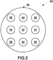
全体的に図2および3を参照すると、図1のセンサシステムで実現することができる導電要素の様々な型および構成が与えられている。図2に示すように、導電要素が導電シャフトである第1のプローブ50が実現される。導電シャフトは、中心導体52、第1のグループの導電要素54、および所定のパターンに配列された第2のグループの導電要素56を備える。中心導電要素52は、プローブ12による全測定範囲でプローブ12に結合することができる。第1のグループの導電要素54は、面積(A)を増大するために中心導体52に結合することができる。追加の面積が必要である場合には、第2のグループの導電要素56を中心導体52および第1のグループの導電要素54に結合することができる。しかし、他の構成を使用することができる。外側導電要素58は、導電要素52、54、および56のまわりに配置されて、戻り経路として作用し、かつ導電要素52、54、および56を電気的な雑音および干渉から遮蔽する。他の実施形態では、使用されない導電要素はどれも外側導電要素58に結合することができる。
Referring generally to FIGS. 2 and 3, various types and configurations of conductive elements that can be realized with the sensor system of FIG. 1 are provided. As shown in FIG. 2, a
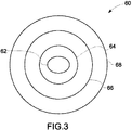
図3は、プローブ60の他の例示の実施形態を示す。プローブ60は、中心導体要素62、および中心導電要素62を環状パターンで取り囲む円筒形導電要素64および68を備える。外側導電要素68は、導電要素62、64および66のまわりに配置されて、キャパシタンスおよび/または間隔の測定に及ぼすどのような電気的な雑音および干渉の影響も減少させる。再び、プローブ60は、所望の測定範囲に基づいてより少ない数またはより多い数の導電要素を有することができる。さらに、導電要素64および68は、プローブ60の分解能を高めるために中心導電要素62に選択的に結合することができる。
FIG. 3 shows another exemplary embodiment of the
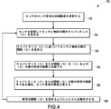
全体的に図4を参照すると、図1のセンサシステム10を動作させる例示の方法70が図示されている。最初に、ブロック72で表すように、外部物体のセンサからの隔たりを測定するために、センサのセンサ要素の初期構成が選択される。次に、ブロック74で、センサからの測定データを使用して、センサと外部物体の間のキャパシタンス(C)を定める。ブロック76で表すように、センサと外部物体の間の間隔(S)がセンサで感知されたキャパシタンス(C)に基づいて定められる。次に、ブロック78で表すように、測定されたキャパシタンス(C)または間隔(S)が、キャパシタンス(C)および間隔(S)の値の所望の範囲と比較される。
Referring generally to FIG. 4, an
測定されたキャパシタンス(C)または間隔(S)がキャパシタンス(C)および/または間隔(S)の所望の範囲の外にある場合、ブロック80で表すように、センサの構成が変更される。センサの構成は、より多くの導電要素をセンサの初期構成に結合することで変更することができる。もしくは、センサの構成は、センサの初期構成から導電要素を取り除いて変えることができる。最後に、ブロック82で表すように、変更された構成を使用してシステムを動作させて、所望の間隔を定める。当業者は理解するように、本方法のステップ74〜82は、異なる時点にセンサと外部物体の間の所望の間隔を実現するように繰り返すことができる。
If the measured capacitance (C) or spacing (S) is outside the desired range of capacitance (C) and / or spacing (S), the configuration of the sensor is changed, as represented by
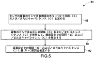
図5は、図1のセンサシステム10を動作させる他の例示の方法84を示す。図示された方法では、ブロック86で表すように、間隔(S)および/またはキャパシタンス(C)は、複数のセンサ要素構成の各々について定められる。次に、ブロック88で表すように、複数のセンサ要素構成で測定されたような間隔(S)および/またはキャパシタンス(C)は、最適な間隔(S)および/またはキャパシタンス(C)の設定を特定するために解析される。測定された間隔(S)および/またはキャパシタンス(C)の解析は、実時間で行うことができる。もしくは、測定された間隔(S)および/またはキャパシタンス(C)の解析は、オフラインで行うことができる。後で、ブロック90に表すように、所望の隙間または間隔(S)が、最適設定で測定された間隔(S)および/またはキャパシタンス(C)に基づいて推定される。
FIG. 5 illustrates another
以上で説明した測定技術は、静止物体と近接した移動部分の間の隙間の正確な測定を実現する。以上で説明した方法の様々な態様は、広い距離範囲にわたった隙間測定が要求される用途で有用である。例えば、上で説明した技術は、航空機エンジンの回転部品と静止部品の間の隙間を測定するために使用することができる。上で言及したように、ここで説明した方法は、物体間の距離を測定するセンサの面積を調整するようにセンサの導電要素を選択的に結合することによって、距離の広い範囲にわたった測定に有利であることがある。 The measurement technique described above realizes an accurate measurement of the gap between a stationary object and a moving part in close proximity. The various aspects of the method described above are useful in applications that require gap measurement over a wide distance range. For example, the techniques described above can be used to measure the clearance between rotating and stationary parts of an aircraft engine. As mentioned above, the method described here measures over a wide range of distances by selectively combining the sensor's conductive elements to adjust the area of the sensor that measures the distance between objects. May be advantageous.
本発明の特定の特徴だけを本明細書で図示し説明したが、多くの修正および変更が当業者の心に浮かぶであろう。したがって、理解すべきことであるが、添付の特許請求の範囲は、本発明の真の精神に含まれるような全ての修正および変更を範囲に含む意図である。なお、特許請求の範囲に記載された符号は、理解容易のためであってなんら発明の技術的範囲を実施例に限縮するものではない。 While only certain features of the invention have been illustrated and described herein, many modifications and changes will occur to those skilled in the art. Therefore, it is to be understood that the appended claims are intended to cover all modifications and changes as fall within the true spirit of the invention. In addition, the code | symbol described in the claim is for easy understanding, and does not limit the technical scope of an invention to an Example at all.
10 センサシステム
12 センサ(プローブ)
14、16、18 導電要素
30 導電要素(戻り経路)
20 プローブ制御システム
22、24、26 スイッチ
10
14, 16, 18
20
Claims (10)
前記センサ(12)に結合された制御システム(20)と、を備えるセンサシステム(10)であって、前記制御システム(20)が、前記感知されたパラメータを表す前記出力信号に基づいて前記センサ(12)の物理特性を変えるように動作可能であるセンサシステム(10)。 A sensor (12) operable to provide an output signal representative of the sensed parameter;
A control system (20) coupled to the sensor (12), wherein the control system (20) is based on the output signal representative of the sensed parameter. A sensor system (10) operable to change the physical properties of (12).
前記複数のスイッチ(22)の各々を制御して、前記複数の導電要素(14)の各々を前記センサ(12)の出力に選択的に結合するように動作可能な制御システム(20)、を備えるセンサシステム(10)。 A sensor (12) operable to provide an output signal representative of a sensed parameter, wherein a plurality of conductive elements (14) and each of the plurality of conductive elements (14) is connected to the sensor (12). A sensor (12) comprising a plurality of switches (22) operable to selectively couple to an output; and
A control system (20) operable to control each of the plurality of switches (22) to selectively couple each of the plurality of conductive elements (14) to the output of the sensor (12); A sensor system (10) comprising.
パラメータを感知するように動作可能な複数の導電要素(14)と、
前記複数の導電要素(14)の各々を前記センサ(12)の出力に選択的に結合するように動作可能な複数のスイッチ(22)と、を備える多レンジセンサ(12)。 A multi-range sensor (12),
A plurality of conductive elements (14) operable to sense parameters;
A multi-range sensor (12) comprising a plurality of switches (22) operable to selectively couple each of the plurality of conductive elements (14) to the output of the sensor (12).
センサによって感知されたパラメータを表す出力信号を受け取るステップと、
前記感知されたパラメータを表す出力信号に基づいて、前記センサの物理特性を制御するステップと、を備える方法。 A method for operating a sensor system, comprising:
Receiving an output signal representative of the parameter sensed by the sensor;
Controlling physical properties of the sensor based on an output signal representative of the sensed parameter.
センサによって感知されたパラメータを表す出力信号を受け取るステップと、
前記感知されたパラメータを表す前記出力信号に基づいて、複数の導電要素を前記センサの出力に選択的に結合するステップと、を備える方法。 A method for operating a sensor system, comprising:
Receiving an output signal representative of the parameter sensed by the sensor;
Selectively coupling a plurality of conductive elements to the output of the sensor based on the output signal representative of the sensed parameter.
センサの複数の構成によって感知されたパラメータを表す複数の出力信号を受け取るステップと、
前記感知されたパラメータを表す前記複数の出力信号を解析するステップと、
前記感知されたパラメータの所望の範囲を測定するために前記センサの所望の構成を選択するステップと、を備える方法。
A method for operating a sensor system, comprising:
Receiving a plurality of output signals representing parameters sensed by a plurality of configurations of the sensor;
Analyzing the plurality of output signals representing the sensed parameter;
Selecting a desired configuration of the sensor to measure a desired range of the sensed parameter.
Applications Claiming Priority (1)
| Application Number | Priority Date | Filing Date | Title |
|---|---|---|---|
| US10/951,562 US7332915B2 (en) | 2004-09-28 | 2004-09-28 | Sensor system and method of operating the same |
Publications (2)
| Publication Number | Publication Date |
|---|---|
| JP2006098403A true JP2006098403A (en) | 2006-04-13 |
| JP2006098403A5 JP2006098403A5 (en) | 2008-11-13 |
Family
ID=35355727
Family Applications (1)
| Application Number | Title | Priority Date | Filing Date |
|---|---|---|---|
| JP2005279269A Pending JP2006098403A (en) | 2004-09-28 | 2005-09-27 | Sensor system and operating method thereof |
Country Status (6)
| Country | Link |
|---|---|
| US (1) | US7332915B2 (en) |
| EP (1) | EP1640687B1 (en) |
| JP (1) | JP2006098403A (en) |
| CA (1) | CA2519527C (en) |
| DE (1) | DE602005004217T2 (en) |
| RU (1) | RU2392651C2 (en) |
Cited By (5)
| Publication number | Priority date | Publication date | Assignee | Title |
|---|---|---|---|---|
| JP2007155734A (en) * | 2005-12-06 | 2007-06-21 | General Electric Co <Ge> | Multi-range distance measuring system and method for operating the same |
| JP2010175539A (en) * | 2009-01-27 | 2010-08-12 | General Electric Co <Ge> | Automatic calibration of sensor by sensor parameter download |
| JP2010237144A (en) * | 2009-03-31 | 2010-10-21 | Fujikura Ltd | Obstacle detection device for vehicle, and airbag deployment control device for protecting pedestrian |
| JP2011085549A (en) * | 2009-10-19 | 2011-04-28 | Alps Electric Co Ltd | Capacitance type proximity sensor device, capacitance type motion detector, and input device using them |
| JPWO2010050607A1 (en) * | 2008-10-31 | 2012-03-29 | 株式会社フジクラ | Capacitive sensor |
Families Citing this family (15)
| Publication number | Priority date | Publication date | Assignee | Title |
|---|---|---|---|---|
| US7466143B2 (en) * | 2005-09-16 | 2008-12-16 | General Electric Company | Clearance measurement systems and methods of operation |
| US7215129B1 (en) * | 2006-03-30 | 2007-05-08 | General Electric Company | Multi tip clearance measurement system and method of operation |
| US8615374B1 (en) | 2006-06-09 | 2013-12-24 | Rockwell Automation Technologies, Inc. | Modular, configurable, intelligent sensor system |
| US7404331B2 (en) * | 2006-09-27 | 2008-07-29 | General Electric Company | Sensor assembly, transformers and methods of manufacture |
| US7605595B2 (en) * | 2006-09-29 | 2009-10-20 | General Electric Company | System for clearance measurement and method of operating the same |
| US8177474B2 (en) * | 2007-06-26 | 2012-05-15 | General Electric Company | System and method for turbine engine clearance control with rub detection |
| DE102007047716A1 (en) | 2007-10-05 | 2009-04-09 | Robert Bosch Gmbh | Sensor device for capacitive distance determination |
| US7852092B2 (en) * | 2008-03-25 | 2010-12-14 | General Electric Company | Systems for inspection of shrouds |
| US7994800B2 (en) * | 2008-03-25 | 2011-08-09 | General Electric Company | Systems and methods for online phase calibration |
| US8272246B2 (en) * | 2008-09-30 | 2012-09-25 | General Electric Company | Electronic self-calibration for sensor clearance |
| US8876460B2 (en) | 2011-08-11 | 2014-11-04 | General Electric Company | Method and apparatus for measuring turbine shell clearance |
| US8970228B2 (en) | 2012-05-31 | 2015-03-03 | General Electric Company | Rotational clearance measurement system and method of operation |
| US9417048B2 (en) | 2012-10-31 | 2016-08-16 | General Electric Company | Capacitive sensor device and method of manufacture |
| US9476318B2 (en) * | 2013-09-03 | 2016-10-25 | General Electric Company | Systems and methods to monitor a rotating component |
| US9587511B2 (en) | 2013-12-13 | 2017-03-07 | General Electric Company | Turbomachine cold clearance adjustment |
Citations (16)
| Publication number | Priority date | Publication date | Assignee | Title |
|---|---|---|---|---|
| JPS4955360U (en) * | 1972-08-23 | 1974-05-16 | ||
| JPS5759101A (en) * | 1980-09-26 | 1982-04-09 | Hiromi Ogasawara | Noncontacting infinitesimal displacement gauge |
| JPS5914007U (en) * | 1982-07-20 | 1984-01-27 | イ−グル工業株式会社 | surface roughness meter |
| JPS6280502A (en) * | 1985-10-03 | 1987-04-14 | Stanley Electric Co Ltd | Electrostatic capacity type proximity detecting device |
| JPH04231802A (en) * | 1990-05-29 | 1992-08-20 | General Electric Co <Ge> | Electric-capacitance gap meter |
| JPH07198312A (en) * | 1993-11-17 | 1995-08-01 | Soc Natl Etud Constr Mot Aviat <Snecma> | Device for dynamically measuring distance between facing surfaces of rotor and stator in rotary machine |
| JPH07198309A (en) * | 1991-06-11 | 1995-08-01 | Weidmueller Interface Gmbh & Co | Capacitance sensor device |
| JPH09203681A (en) * | 1996-01-29 | 1997-08-05 | Fuji Electric Co Ltd | Pressure detector |
| JPH09297174A (en) * | 1996-05-02 | 1997-11-18 | Honda Motor Co Ltd | Multi-beam radar equipment |
| JPH11258331A (en) * | 1998-03-11 | 1999-09-24 | Mitsubishi Electric Corp | Radar device |
| JP2000082658A (en) * | 1998-09-04 | 2000-03-21 | Canon Inc | Surface position detecting equipment, aligner and device manufacturing method |
| JP2001094408A (en) * | 1999-07-22 | 2001-04-06 | Sumitomo Metal Ind Ltd | Static capacitance type sensor, static capacitance type parts and article mount body |
| US6401541B1 (en) * | 1999-11-03 | 2002-06-11 | Kulite Semiconductor Products, Inc. | Multiple pressure sensing system |
| JP2003021566A (en) * | 2001-07-10 | 2003-01-24 | Teijin Seiki Co Ltd | Silicon-diaphragm type vacuum pressure sensor device and pressure measuring method using the same |
| JP2003028741A (en) * | 2001-07-11 | 2003-01-29 | Toyota Central Res & Dev Lab Inc | Electrical capacitance sensor device |
| JP2005134131A (en) * | 2003-10-28 | 2005-05-26 | Oki Electric Ind Co Ltd | Capacitance type distance measuring instrument |
Family Cites Families (9)
| Publication number | Priority date | Publication date | Assignee | Title |
|---|---|---|---|---|
| SU964438A1 (en) | 1976-07-19 | 1982-10-07 | Институт Электродинамики Ан Усср | Capacitive transformer bridge for measuring displacements |
| US5119036A (en) | 1990-05-29 | 1992-06-02 | General Electric Company | Electrical capacitance clearanceometer |
| US5166626A (en) | 1990-05-29 | 1992-11-24 | General Electric Company | Electrical capacitance clearanceometer |
| JP3732919B2 (en) * | 1996-12-19 | 2006-01-11 | トヨタ自動車株式会社 | Capacitive angle detector |
| US6441623B1 (en) * | 1999-07-29 | 2002-08-27 | Ab Automotive Electronics Ltd. | Capacitive proximity sensor for automotive use |
| US6593755B1 (en) * | 2000-07-31 | 2003-07-15 | Banner Engineering Corporation | Method and apparatus for detection sensor shielding |
| US6744264B2 (en) * | 2002-04-25 | 2004-06-01 | Motorola, Inc. | Testing circuit and method for MEMS sensor packaged with an integrated circuit |
| US6774642B2 (en) * | 2002-08-27 | 2004-08-10 | Delphi Technologies, Inc. | Capacitive angular position sensor |
| JP3858865B2 (en) * | 2003-08-29 | 2006-12-20 | セイコーエプソン株式会社 | Capacitance detection device |
-
2004
- 2004-09-28 US US10/951,562 patent/US7332915B2/en active Active
-
2005
- 2005-09-15 CA CA2519527A patent/CA2519527C/en not_active Expired - Fee Related
- 2005-09-26 EP EP05255982A patent/EP1640687B1/en active Active
- 2005-09-26 DE DE602005004217T patent/DE602005004217T2/en active Active
- 2005-09-27 RU RU2005130123/09A patent/RU2392651C2/en not_active IP Right Cessation
- 2005-09-27 JP JP2005279269A patent/JP2006098403A/en active Pending
Patent Citations (16)
| Publication number | Priority date | Publication date | Assignee | Title |
|---|---|---|---|---|
| JPS4955360U (en) * | 1972-08-23 | 1974-05-16 | ||
| JPS5759101A (en) * | 1980-09-26 | 1982-04-09 | Hiromi Ogasawara | Noncontacting infinitesimal displacement gauge |
| JPS5914007U (en) * | 1982-07-20 | 1984-01-27 | イ−グル工業株式会社 | surface roughness meter |
| JPS6280502A (en) * | 1985-10-03 | 1987-04-14 | Stanley Electric Co Ltd | Electrostatic capacity type proximity detecting device |
| JPH04231802A (en) * | 1990-05-29 | 1992-08-20 | General Electric Co <Ge> | Electric-capacitance gap meter |
| JPH07198309A (en) * | 1991-06-11 | 1995-08-01 | Weidmueller Interface Gmbh & Co | Capacitance sensor device |
| JPH07198312A (en) * | 1993-11-17 | 1995-08-01 | Soc Natl Etud Constr Mot Aviat <Snecma> | Device for dynamically measuring distance between facing surfaces of rotor and stator in rotary machine |
| JPH09203681A (en) * | 1996-01-29 | 1997-08-05 | Fuji Electric Co Ltd | Pressure detector |
| JPH09297174A (en) * | 1996-05-02 | 1997-11-18 | Honda Motor Co Ltd | Multi-beam radar equipment |
| JPH11258331A (en) * | 1998-03-11 | 1999-09-24 | Mitsubishi Electric Corp | Radar device |
| JP2000082658A (en) * | 1998-09-04 | 2000-03-21 | Canon Inc | Surface position detecting equipment, aligner and device manufacturing method |
| JP2001094408A (en) * | 1999-07-22 | 2001-04-06 | Sumitomo Metal Ind Ltd | Static capacitance type sensor, static capacitance type parts and article mount body |
| US6401541B1 (en) * | 1999-11-03 | 2002-06-11 | Kulite Semiconductor Products, Inc. | Multiple pressure sensing system |
| JP2003021566A (en) * | 2001-07-10 | 2003-01-24 | Teijin Seiki Co Ltd | Silicon-diaphragm type vacuum pressure sensor device and pressure measuring method using the same |
| JP2003028741A (en) * | 2001-07-11 | 2003-01-29 | Toyota Central Res & Dev Lab Inc | Electrical capacitance sensor device |
| JP2005134131A (en) * | 2003-10-28 | 2005-05-26 | Oki Electric Ind Co Ltd | Capacitance type distance measuring instrument |
Cited By (5)
| Publication number | Priority date | Publication date | Assignee | Title |
|---|---|---|---|---|
| JP2007155734A (en) * | 2005-12-06 | 2007-06-21 | General Electric Co <Ge> | Multi-range distance measuring system and method for operating the same |
| JPWO2010050607A1 (en) * | 2008-10-31 | 2012-03-29 | 株式会社フジクラ | Capacitive sensor |
| JP2010175539A (en) * | 2009-01-27 | 2010-08-12 | General Electric Co <Ge> | Automatic calibration of sensor by sensor parameter download |
| JP2010237144A (en) * | 2009-03-31 | 2010-10-21 | Fujikura Ltd | Obstacle detection device for vehicle, and airbag deployment control device for protecting pedestrian |
| JP2011085549A (en) * | 2009-10-19 | 2011-04-28 | Alps Electric Co Ltd | Capacitance type proximity sensor device, capacitance type motion detector, and input device using them |
Also Published As
| Publication number | Publication date |
|---|---|
| DE602005004217T2 (en) | 2009-01-02 |
| US7332915B2 (en) | 2008-02-19 |
| EP1640687A1 (en) | 2006-03-29 |
| US20060066318A1 (en) | 2006-03-30 |
| RU2392651C2 (en) | 2010-06-20 |
| EP1640687B1 (en) | 2008-01-09 |
| DE602005004217D1 (en) | 2008-02-21 |
| CA2519527A1 (en) | 2006-03-28 |
| CA2519527C (en) | 2014-03-04 |
| RU2005130123A (en) | 2007-04-10 |
Similar Documents
| Publication | Publication Date | Title |
|---|---|---|
| JP2006098403A (en) | Sensor system and operating method thereof | |
| EP2211139B1 (en) | Automated sensor specific calibration through sensor parameter download | |
| EP1795861B1 (en) | Multi-range clearance measurement system and method of operation | |
| JP6967376B2 (en) | Encoder, measurement method, and measurement system | |
| US6717418B2 (en) | Method and apparatus for measuring turbine blade tip clearance | |
| US8348504B2 (en) | Wireless temperature measurement system and methods of making and using same | |
| RU2231751C2 (en) | Apparatus for measuring gaps at different depth values of abrasive wear | |
| US9709376B2 (en) | High sensitivity inductive sensor for measuring blade tip clearance | |
| US20060132147A1 (en) | System and method for measuring clearance between two objects | |
| KR20070099440A (en) | Multi tip clearance measurement system and method of operation | |
| US7180305B2 (en) | Sensor systems and methods of operation | |
| Baroncini et al. | A simple interface circuit for micromachined gas sensors | |
| CN110388990A (en) | A kind of wireless remote-measuring system for the measurement of engine rotating components temperature | |
| US9851324B1 (en) | Sensing apparatus and material sensing method | |
| US6426635B1 (en) | Galvanometer position detector | |
| KR20090132921A (en) | System for automatic calibration of thermocouple and method for calibration using the same | |
| JP3946827B2 (en) | Proximity detector | |
| Soto et al. | Real Time Condition Monitoring of Electric Propulsion and Generation System Using Passive Battery-Free RF Temperature Sensor | |
| CN206399994U (en) | A kind of high resolution measurement change-over circuit | |
| EP3380815B1 (en) | Multi-mode sensor | |
| Ouyang et al. | Approximate engineering method for detection of magneto-resistive proximity sensor | |
| KR20230150302A (en) | High-resolution absolute vector encoder | |
| SU1208471A1 (en) | Method of calibrating contactless object range pickup | |
| JP2006105666A (en) | Interference electromagnetic wave measuring device |
Legal Events
| Date | Code | Title | Description |
|---|---|---|---|
| A521 | Request for written amendment filed |
Free format text: JAPANESE INTERMEDIATE CODE: A523 Effective date: 20080925 |
|
| A621 | Written request for application examination |
Free format text: JAPANESE INTERMEDIATE CODE: A621 Effective date: 20080925 |
|
| A977 | Report on retrieval |
Free format text: JAPANESE INTERMEDIATE CODE: A971007 Effective date: 20101015 |
|
| A131 | Notification of reasons for refusal |
Free format text: JAPANESE INTERMEDIATE CODE: A131 Effective date: 20101026 |
|
| A601 | Written request for extension of time |
Free format text: JAPANESE INTERMEDIATE CODE: A601 Effective date: 20110126 |
|
| RD02 | Notification of acceptance of power of attorney |
Free format text: JAPANESE INTERMEDIATE CODE: A7422 Effective date: 20110126 |
|
| RD04 | Notification of resignation of power of attorney |
Free format text: JAPANESE INTERMEDIATE CODE: A7424 Effective date: 20110126 |
|
| A602 | Written permission of extension of time |
Free format text: JAPANESE INTERMEDIATE CODE: A602 Effective date: 20110131 |
|
| A521 | Request for written amendment filed |
Free format text: JAPANESE INTERMEDIATE CODE: A523 Effective date: 20110425 |
|
| A131 | Notification of reasons for refusal |
Free format text: JAPANESE INTERMEDIATE CODE: A131 Effective date: 20110726 |
|
| A601 | Written request for extension of time |
Free format text: JAPANESE INTERMEDIATE CODE: A601 Effective date: 20111025 |
|
| A602 | Written permission of extension of time |
Free format text: JAPANESE INTERMEDIATE CODE: A602 Effective date: 20111028 |
|
| A02 | Decision of refusal |
Free format text: JAPANESE INTERMEDIATE CODE: A02 Effective date: 20120814 |