RU2392651C2 - Sensor system and its functioning method - Google Patents
Sensor system and its functioning method Download PDFInfo
- Publication number
- RU2392651C2 RU2392651C2 RU2005130123/09A RU2005130123A RU2392651C2 RU 2392651 C2 RU2392651 C2 RU 2392651C2 RU 2005130123/09 A RU2005130123/09 A RU 2005130123/09A RU 2005130123 A RU2005130123 A RU 2005130123A RU 2392651 C2 RU2392651 C2 RU 2392651C2
- Authority
- RU
- Russia
- Prior art keywords
- sensor
- conductive elements
- area
- output signal
- probe
- Prior art date
Links
Images

Classifications
-
- G—PHYSICS
- G01—MEASURING; TESTING
- G01D—MEASURING NOT SPECIALLY ADAPTED FOR A SPECIFIC VARIABLE; ARRANGEMENTS FOR MEASURING TWO OR MORE VARIABLES NOT COVERED IN A SINGLE OTHER SUBCLASS; TARIFF METERING APPARATUS; MEASURING OR TESTING NOT OTHERWISE PROVIDED FOR
- G01D5/00—Mechanical means for transferring the output of a sensing member; Means for converting the output of a sensing member to another variable where the form or nature of the sensing member does not constrain the means for converting; Transducers not specially adapted for a specific variable
- G01D5/12—Mechanical means for transferring the output of a sensing member; Means for converting the output of a sensing member to another variable where the form or nature of the sensing member does not constrain the means for converting; Transducers not specially adapted for a specific variable using electric or magnetic means
- G01D5/14—Mechanical means for transferring the output of a sensing member; Means for converting the output of a sensing member to another variable where the form or nature of the sensing member does not constrain the means for converting; Transducers not specially adapted for a specific variable using electric or magnetic means influencing the magnitude of a current or voltage
- G01D5/24—Mechanical means for transferring the output of a sensing member; Means for converting the output of a sensing member to another variable where the form or nature of the sensing member does not constrain the means for converting; Transducers not specially adapted for a specific variable using electric or magnetic means influencing the magnitude of a current or voltage by varying capacitance
- G01D5/241—Mechanical means for transferring the output of a sensing member; Means for converting the output of a sensing member to another variable where the form or nature of the sensing member does not constrain the means for converting; Transducers not specially adapted for a specific variable using electric or magnetic means influencing the magnitude of a current or voltage by varying capacitance by relative movement of capacitor electrodes
- G01D5/2417—Mechanical means for transferring the output of a sensing member; Means for converting the output of a sensing member to another variable where the form or nature of the sensing member does not constrain the means for converting; Transducers not specially adapted for a specific variable using electric or magnetic means influencing the magnitude of a current or voltage by varying capacitance by relative movement of capacitor electrodes by varying separation
-
- G—PHYSICS
- G01—MEASURING; TESTING
- G01B—MEASURING LENGTH, THICKNESS OR SIMILAR LINEAR DIMENSIONS; MEASURING ANGLES; MEASURING AREAS; MEASURING IRREGULARITIES OF SURFACES OR CONTOURS
- G01B7/00—Measuring arrangements characterised by the use of electric or magnetic techniques
- G01B7/14—Measuring arrangements characterised by the use of electric or magnetic techniques for measuring distance or clearance between spaced objects or spaced apertures
Abstract
Description
Область и уровень техникиField and level of technology
Изобретение относится к сенсорным системам, в частности к сенсорной системе, выполненной с возможностью регулирования физической характеристики датчика в соответствии с выходным сигналом датчика.The invention relates to sensor systems, in particular to a sensor system configured to control the physical characteristics of the sensor in accordance with the output signal of the sensor.
Для измерения расстояния между двумя объектами используются различные типы датчиков. Эти датчики используются в различных применениях. Например, турбина имеет лопатку турбины, расположенную вблизи бандажа. Зазор между лопаткой турбины и бандажом зависит от температуры лопатки турбины. Например, зазор между бандажом и лопаткой турбины наибольший, когда турбина холодная, и постепенно уменьшается при нагревании турбины. Желательно, чтобы зазор между лопаткой турбины и бандажом поддерживался для обеспечения надежной и эффективной работы турбины. Датчик может находиться в турбине для измерения расстояния между лопаткой турбины и бандажом. Это расстояние можно использовать для непосредственного перемещения бандажа, чтобы обеспечивать требуемое смещение между бандажом и лопаткой турбины.Various types of sensors are used to measure the distance between two objects. These sensors are used in various applications. For example, a turbine has a turbine blade located near the bandage. The clearance between the turbine blade and the bandage depends on the temperature of the turbine blade. For example, the gap between the bandage and the turbine blade is greatest when the turbine is cold, and gradually decreases when the turbine is heated. It is desirable that the gap between the turbine blade and the retainer be maintained to ensure reliable and efficient operation of the turbine. The sensor may be located in the turbine to measure the distance between the turbine blade and the bandage. This distance can be used to directly move the band to provide the required offset between the band and the turbine blade.
В некоторых применениях для измерения расстояния между двумя объектами применяют емкостный зонд. Обычно размеры наконечника емкостного зонда подбирают такими, чтобы соответствовать определенному расстоянию смещения между двумя объектами. Применение небольших зондов обычно ограничено измерениями небольшого расстояния, как результат отношения сигнал-шум. Аналогично применение больших зондов ограничено измерениями больших расстояний, поскольку их разрешающая способность для расстояния между двумя объектами хуже, чем для измерений небольших расстояний. Поэтому обычные емкостные зонды могут быть неточными применительно к расстояниям смещения, которые не являются расстояниями, на измерение которых рассчитан наконечник зонда.In some applications, a capacitive probe is used to measure the distance between two objects. Typically, the size of the tip of the capacitive probe is selected so as to correspond to a certain displacement distance between two objects. The use of small probes is usually limited to short distance measurements as a result of the signal-to-noise ratio. Similarly, the use of large probes is limited to measurements of large distances, since their resolution for the distance between two objects is worse than for measurements of small distances. Therefore, conventional capacitive probes may be inaccurate with respect to displacement distances that are not the distances for which the probe tip is designed.
Соответственно, существует необходимость обеспечения сенсорной системы, осуществляющей точное измерение зазора между двумя объектами, смещаемыми относительно друг друга по всему диапазону смещения.Accordingly, there is a need to provide a sensor system that accurately measures the gap between two objects that are offset relative to each other over the entire range of displacement.
Сущность изобретенияSUMMARY OF THE INVENTION
Согласно одному аспекту настоящего изобретения обеспечивается сенсорная система. Сенсорная система содержит датчик, выполненный с возможностью обеспечения выходного сигнала, характеризующего определяемый параметр. Сенсорная система также содержит систему управления, подключенную к датчику, причем система управления выполнена с возможностью изменения физической характеристики датчика на основании выходного сигнала, характеризующего определяемый параметр.According to one aspect of the present invention, a sensor system is provided. The sensor system comprises a sensor configured to provide an output signal characterizing the determined parameter. The sensor system also includes a control system connected to the sensor, and the control system is configured to change the physical characteristics of the sensor based on the output signal characterizing the determined parameter.
Согласно еще одному аспекту настоящего изобретения предусмотрен способ функционирования сенсорной системы. Согласно этому способу принимают от датчика выходной сигнал, характеризующий определяемый параметр, и регулируют физическую характеристику датчика на основании выходного сигнала, характеризующего определяемый параметр.According to another aspect of the present invention, a method for operating a sensor system is provided. According to this method, an output signal characterizing the determined parameter is received from the sensor, and the physical characteristic of the sensor is adjusted based on the output signal characterizing the determined parameter.
ЧертежиBlueprints
Эти и прочие признаки, аспекты и преимущества настоящего изобретения станут более понятными из приводимого ниже подробного описания в совокупности с прилагаемыми чертежами, на которых аналогичные обозначения представляют одинаковые детали.These and other features, aspects and advantages of the present invention will become more apparent from the following detailed description taken in conjunction with the accompanying drawings, in which like designations represent the same details.
Фиг. 1 - схематическое представление сенсорной системы для измерения зазора во вращающейся машине согласно варианту осуществления изобретения;FIG. 1 is a schematic representation of a sensor system for measuring clearance in a rotating machine according to an embodiment of the invention;
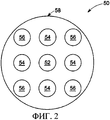
фиг. 2 - схематическое представление датчика с конфигурированным расположением чувствительных элементов согласно варианту осуществления изобретения;FIG. 2 is a schematic representation of a sensor with a configured arrangement of sensors according to an embodiment of the invention;
фиг. 3 - схематическое представление датчика с кольцевым расположением чувствительных элементов согласно варианту осуществления изобретения;FIG. 3 is a schematic representation of a sensor with an annular arrangement of sensors according to an embodiment of the invention;
фиг. 4 - блок-схема, иллюстрирующая способ функционирования сенсорной системы согласно фиг. 1, согласно варианту осуществления изобретения;FIG. 4 is a flowchart illustrating a method for operating the sensor system of FIG. 1, according to an embodiment of the invention;
фиг. 5 - блок-схема, иллюстрирующая способ функционирования сенсорной системы согласно фиг. 1, в соответствии с вариантом осуществления изобретения.FIG. 5 is a flowchart illustrating a method of operating a sensor system according to FIG. 1, in accordance with an embodiment of the invention.
Подробное описаниеDetailed description
Как показано на фиг. 1, обеспечена сенсорная система, обозначенная позицией 10. Сенсорная система 10 содержит зонд 12, выполненный с возможностью обеспечения выходного сигнала, характеризующего определяемый параметр. Зонд 12 содержит первый проводящий элемент 14, второй проводящий элемент 16 и третий проводящий элемент 18. Однако в сенсорной системе 10 можно использовать и меньшее, и большее число проводящих элементов. Кроме того, согласно варианту осуществления изобретения сенсорная система 10 содержит систему 20 управления зондом, первый переключатель 22, второй переключатель 24 и третий переключатель 26 для избирательного подключения проводящих элементов 14, 16 и 18 к системе 20 управления зондом. Согласно приводимому ниже более подробному описанию система 20 управления зондом выполнена с возможностью оптимизации конфигурации зонда 12 согласно выходному сигналу зонда 12 путем избирательного подключения вместе проводящих элементов 14, 16 и 18. Проводящие элементы 14, 16 и 18 также подключены к системе 28 управления отделяющим расстоянием, которая регулирует отделяющее расстояние между зондом 12 и объектом согласно приводимому ниже более подробному описанию. Также обеспечен дополнительный проводящий элемент 30, который действует как обратный канал и экранирует зонд 12 от шума и помех. Для экранирования зонда 12 к проводящему элементу 30 можно подключить и большее число проводящих элементов. Проводящие элементы 14, 16 и 18 также подключены к системе 28 управления отделяющим расстоянием и к системе 20 управления зондом по проводам 32 и 34 соответственно.As shown in FIG. 1, a sensor system is provided, indicated at 10. The sensor system 10 comprises a probe 12 configured to provide an output signal characterizing a determined parameter. The probe 12 comprises a first conductive element 14, a second conductive element 16, and a third conductive element 18. However, in the sensor system 10, both fewer and more conductive elements can be used. In addition, according to an embodiment of the invention, the sensor system 10 comprises a probe control system 20, a
В поясняемом варианте осуществления зонд 12 является емкостным зондом, который определяет электрическую емкость между зондом 12 и объектом 36. Электрическая емкость между двумя объектами зависит от площади (А) перекрытия и отделяющего расстояния (S) 38 между зондом 12 и объектом 36. В сенсорной системе 10 площадь (А) перекрытия является площадью зонда 12, т.к. площадь объекта 36 больше площади зонда 12. Электрическая емкость между двумя параллельными пластинами определяется следующим уравнением:In the illustrated embodiment, the probe 12 is a capacitive probe that determines the electric capacitance between the probe 12 and the object 36. The electric capacitance between the two objects depends on the area (A) of the overlap and the separation distance (S) 38 between the probe 12 and the object 36. In the sensor system 10, the area (A) of the overlap is the area of the probe 12, because the area of the object 36 is greater than the area of the probe 12. The electric capacitance between two parallel plates is determined by the following equation:
![]()
![]()
где С - электрическая емкость;where C is the electric capacitance;
ε - диэлектрическая проницаемость среды между параллельными пластинами;ε is the dielectric constant of the medium between parallel plates;
А - площадь перекрытия между параллельными пластинами; иA is the area of overlap between parallel plates; and
S - отделяющее расстояние между параллельными пластинами.S is the separating distance between the parallel plates.
Определяя электрическую емкость (С), зонд 12 обеспечивает возможность установить отделяющее расстояние (S) 38 между зондом 12 и объектом 36. Из уравнения (1) можно вывести следующее уравнение отделяющего расстояния (S) в зависимости от электрической емкости (С):By determining the electric capacitance (C), the probe 12 makes it possible to establish a separating distance (S) 38 between the probe 12 and the object 36. From equation (1), the following equation of the separating distance (S) can be derived depending on the electric capacitance (C):
![]()
![]()
Согласно приводимому ниже более подробному описанию система 38 управления отделяющим расстоянием регулирует отделяющее расстояние (S) между зондом 12 и объектом 36 на основании сигнала, характеризующего электрическую емкость (С), принимаемого от зонда 12. В этом варианте осуществления система 28 управления отделяющим расстоянием выполнена с возможностью установления отделяющего расстояния (S) между зондом 12 и объектом 36 по уравнению (2) и данным, запрограммированным в системе 28 управления отделяющим расстоянием. Но система 28 управления отделяющим расстоянием может просто использовать электрическую емкость (С) для регулирования отделяющего расстояния (S) 38 между зондом 12 и объектом 36. Электрическую емкость (С) и/или отделяющее расстояние (S) сравнивают с требуемым значением электрической емкости и/или отделяющего расстояния (S). В соответствии с этим вариантом осуществления система 28 управления отделяющим расстоянием выдает команду на смещение объекта 36 для обеспечения требуемой электрической емкости (С) или отделяющего расстояния (S).According to a more detailed description below, the separation distance control system 38 adjusts the separation distance (S) between the probe 12 and the object 36 based on a signal characterizing the electric capacitance (C) received from the probe 12. In this embodiment, the separation distance control system 28 is configured to the possibility of establishing a separation distance (S) between the probe 12 and the object 36 according to equation (2) and the data programmed in the separation control system 28. But the separation distance control system 28 can simply use the electric capacitance (C) to control the separation distance (S) 38 between the probe 12 and the object 36. The electric capacitance (C) and / or the separation distance (S) are compared with the desired value of the electric capacitance and / or separating distance (S). According to this embodiment, the separation distance control system 28 issues an offset command to the object 36 to provide the required electric capacitance (C) or separation distance (S).
Система 20 управления зондом выполнена с возможностью оптимизации площади (А) зонда 12 для соответствия фактическому отделяющему расстоянию (S) 38 или электрической емкости (С). Система 20 управления зондом уменьшает площадь (А) зонда 12 при уменьшении отделяющего расстояния (S) 38 и увеличивает площадь (А) зонда 12 при увеличении отделяющего расстояния (S) 38. Система 20 управления зондом регулирует площадь (А) зонда 12 путем избирательного замыкания переключателей 22, 24 и 26, тем самым регулируя определенные проводящие элементы 14, 16 и 18, подключенные к системе 28 управления отделяющим расстоянием. Например, если отделяющее расстояние (S) 38 между зондом 12 и объектом 36 небольшое, то система 20 управления зондом может подключить один проводящий элемент 18 не по обратному каналу 30 к системе 28 управления отделяющим расстоянием путем замыкания переключателя 26 и размыкания переключателей 22 и 24. Либо при увеличении отделяющего расстояния (S) 38 между зондом 12 и объектом 36 система 20 управления зондом может оперативно подключить проводящие элементы 14 и 16 к системе 28 управления отделяющим расстоянием путем замыкания переключателей 22 и 24.The probe control system 20 is configured to optimize the area (A) of the probe 12 to match the actual separation distance (S) 38 or the electric capacitance (C). The probe control system 20 reduces the area (A) of the probe 12 when the separation distance (S) 38 decreases and increases the area (A) of the probe 12 when the separation distance (S) 38 increases. The probe control system 20 controls the area (A) of the probe 12 by
В поясняемом варианте осуществления система 20 управления зондом содержит устройство 40 сопряжения для содействия управлению переключателями 22, 24 и 26. Помимо этого, система 20 управления зондом также содержит процессор 42 для обработки сигнала электрической емкости от зонда 12 и для команды направления сигнала устройству сопряжения на размыкание и замыкание переключателей 22, 24 и 26. В этом варианте осуществления система 20 управления зондом также имеет запоминающую схему 44 для хранения предварительно заданных программ, внутренних ссылок и другой информации для управления избирательным подключением проводящих элементов 14, 16 и 18.In the illustrated embodiment, the probe control system 20 includes an interface device 40 for facilitating control of the
Как упомянуто выше, переключатели 22, 24 и 26 используются для подключения проводящих элементов 14, 16 и 18 к зонду 12. Согласно одному из вариантов осуществления переключатели 22, 24 и 26 являются полупроводниковыми переключателями. Согласно другому варианту осуществления переключателями 22, 24 и 26 могут быть механические реле. Согласно еще одному варианту осуществления переключателями 22, 24 и 26 могут быть переключатели в виде радиочастотных микроэлектромеханических систем. Следует отметить, что подключение дополнительных проводящих элементов 16 и 18 через переключатели 24 и 26 увеличивает диапазон измерений, осуществляемых зондом 12. Согласно еще одному варианту осуществления проводящие элементы, не используемые для подключения друг к другу, можно подключить к проводящему элементу 30 для обеспечения дополнительного экранирования. Согласно еще одному варианту осуществления неиспользуемые проводящие элементы можно поддерживать с предварительно заданным потенциалом для уменьшения помех при измерениях.As mentioned above, the
Как показано на фиг. 2 и 3, представлены различные типы и конфигурации проводящих элементов, которые можно выполнить для сенсорной системы согласно фиг. 1. Согласно фиг. 2 обеспечен первый зонд 50, в котором проводящие элементы являются проводящими стержнями. Проводящие стержни имеют центральный проводник 52, первую группу проводящих элементов 54 и вторую группу проводящих элементов 56, расположенных по предварительно определенной схеме. Центральный проводящий элемент 52 можно подключить к зонду 12 для всех диапазонов измерения, выполняемых зондом 12. Первую группу проводящих элементов 54 можно подключить к центральному проводнику 52 для увеличения площади (А). Если необходима дополнительная площадь, то вторую группу проводящих элементов 56 можно подключить к центральному проводнику 52 и к первой группе проводящих элементов 54. Однако можно использовать и другие конфигурации. Внешний проводящий элемент 58 расположен вокруг проводящих элементов 52, 54 и 56 и действует как обратный канал и экранирует проводящие элементы 52, 54 и 56 от электрического шума и помех. Согласно альтернативному варианту осуществления к внешнему проводящему элементу 58 можно подключить любые неиспользуемые проводящие элементы.As shown in FIG. 2 and 3, various types and configurations of conductive elements that can be made for the sensor system according to FIG. 1. According to FIG. 2, a
Фиг. 3 иллюстрирует другой вариант осуществления зонда 60. Зонд 60 содержит центральный проводящий элемент 62 и цилиндрические проводящие элементы 64 и 68 вокруг центрального проводящего элемента 62 в кольцевой конфигурации. Внешний проводящий элемент 68 расположен вокруг проводящих элементов 62, 64 и 66 для снижения воздействия электрического шума и помех на измерение электрической емкости и/или отделяющего расстояния. При этом зонд 60 также может иметь меньшее или большее число проводящих элементов в зависимости от требуемого диапазона измерения. Помимо этого, проводящие элементы 64 и 68 можно избирательно подключить к центральному проводящему элементу 62 для повышения разрешающей способности зонда 60.FIG. 3 illustrates another embodiment of a
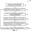
На фиг. 4 представлен приводимый в качестве примера способ 70 функционирования сенсорной системы 10 согласно фиг. 1. Первоначально исходную конфигурацию чувствительных элементов выбирают для измерения отделяющего расстояния между внешним объектом и датчиком (блок 72). Затем в блоке 74 данные измерения от датчика используют для того, чтобы установить электрическую емкость (С) между датчиком и внешним объектом. В блоке 76 отделяющее расстояние (S) между датчиком и внешним объектом устанавливают согласно электрической емкости (С), определяемой датчиком.In FIG. 4 shows an
Затем измеренную электрическую емкость (С) или отделяющее расстояние (S) сравнивают с требуемым диапазоном значений электрической емкости (С) и отделяющего расстояния (S) (блок 78).Then, the measured electric capacitance (C) or separating distance (S) is compared with the desired range of values of the electric capacitance (C) and separating distance (S) (block 78).
Если измеренная электрическая емкость (С) или отделяющее расстояние (S) находятся вне требуемого диапазона электрической емкости (С) и/или отделяющего расстояния, то конфигурацию датчика изменяют (блок 80). Конфигурацию датчика можно модифицировать подключением большего числа элементов к первоначальной конфигурации датчика. Либо конфигурацию датчика можно изменить удалением проводящих элементов из первоначальной конфигурации датчика. Наконец, в блоке 82 система действует с использованием модифицированной конфигурации, чтобы установить требуемое отделяющее расстояние. Специалистам в данной области техники будет ясно, что этапы 74-82 способа можно повторять для обеспечения требуемого отделяющего расстояния между датчиком и внешним объектом в разные моменты времени.If the measured electric capacitance (C) or separating distance (S) is outside the required range of electric capacitance (C) and / or separating distance, then the sensor configuration is changed (block 80). The configuration of the sensor can be modified by connecting more elements to the initial configuration of the sensor. Or, the configuration of the sensor can be changed by removing conductive elements from the initial configuration of the sensor. Finally, at
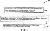
Фиг. 5 иллюстрирует еще один вариант осуществления приводимого в качестве примера способа 84 функционирования сенсорной системы 10 согласно фиг. 1. Согласно поясняемому способу отделяющее расстояние (S) и/или электрическую емкость (С) устанавливают для каждой конфигурации из числа множества конфигураций чувствительных элементов (блок 86). Затем отделяющее расстояние (S) и/или электрическую емкость (С), измеренные множеством конфигураций чувствительных элементов, анализируют для определения задаваемых оптимального отделяющего расстояния (S) и/или электрической емкости (С) (блок 88). Анализ измеренных отделяющего расстояния (S) и/или электрической емкости (С) можно выполнять в реальном времени. Либо анализ измеренных отделяющего расстояния (S) и/или электрической емкости (С) можно выполнять автономно. Затем, как представлено в блоке 90, требуемый зазор или отделяющее расстояние (S) оценивают как оптимально заданные согласно измеренному отделяющему расстоянию (S) или электрической емкости (С).FIG. 5 illustrates yet another embodiment of an
Излагаемый выше способ измерения обеспечивает точное измерение зазора между неподвижным объектом и прилегающей перемещаемой частью. Различные аспекты описываемого выше способа можно применить в устройствах, в которых нужно измерять зазор в широком диапазоне расстояний. Например, описываемый выше способ можно использовать для измерения зазора между вращающимся компонентом и неподвижным компонентом в авиационном двигателе. Как упомянуто выше, излагаемый здесь способ может быть целесообразным для измерений по широкому диапазону расстояний путем избирательного подключения проводящих элементов датчика для регулирования площади датчика для измерения расстояния между объектами.The measurement method described above provides an accurate measurement of the gap between a fixed object and an adjacent movable part. Various aspects of the method described above can be applied to devices in which a gap must be measured over a wide range of distances. For example, the method described above can be used to measure the clearance between a rotating component and a stationary component in an aircraft engine. As mentioned above, the method described here may be appropriate for measurements over a wide range of distances by selectively connecting conductive sensor elements to adjust the area of the sensor to measure the distance between objects.
Выше изложены только некоторые признаки изобретения, но специалистам в данной области техники будут понятны многие модификации и изменения. Поэтому подразумевается, что прилагаемая формула изобретения включает в себя все эти модификации и изменения в рамках концепции настоящего изобретения.Only some of the features of the invention are set forth above, but many modifications and changes will be apparent to those skilled in the art. Therefore, it is understood that the appended claims include all of these modifications and changes within the concept of the present invention.
ПЕРЕЧЕНЬ ЭЛЕМЕНТОВLIST OF ELEMENTS
10 - сенсорная система10 - sensor system
12 - датчик12 - sensor
14-18 - проводящие элементы14-18 - conductive elements
20 - система управления зондом20 - probe control system
22-26 - переключатели22-26 - switches
28 - система управления отделяющим расстоянием28 - separation control system
30 - экранирующий элемент30 - shielding element
32 - кабель для подключения чувствительных элементов к системе управления отделяющим расстоянием32 - cable for connecting sensitive elements to the separation distance control system
34 - кабель для подключения чувствительных элементов к системе управления зондом34 - cable for connecting sensors to the probe control system
36 - внешний объект36 - external object
38 - зазор38 - clearance
40 - устройство сопряжения40 - interface device
42 - процессор42 - processor
44 - запоминающее устройство44 - storage device
50 - датчик с определенной схемой расположения проводящих элементов50 - sensor with a specific arrangement of conductive elements
52 - центральный чувствительный элемент52 - central sensing element
54 - первая схема расположения проводящих элементов54 is a first arrangement of conductive elements
56 - вторая схема расположения проводящих элементов56 is a second arrangement of conductive elements
58 - экранирующий проводящий элемент58 - shielding conductive element
60 - датчик с кольцевым расположением чувствительных элементов60 - sensor with a ring arrangement of sensitive elements
64 - первые проводящие элементы64 - the first conductive elements
66 - вторые проводящие элементы66 - second conductive elements
68 - экранирующий проводящий элемент68 - shielding conductive element
70 - схема последовательности функционирования сенсорной системы70 is a sequence diagram of a sensor system
72-82 - этапы способа72-82 - method steps
84 - схема последовательности функционирования сенсорной системы со многими измерениями84 is a flow diagram of a sensor system with many measurements.
86-90 - этапы способа86-90 - method steps
Claims (8)
при этом датчик (12) содержит множество проводящих элементов (14) и множество переключателей (22), выполненных с возможностью избирательного подключения каждого из множества проводящих элементов (14) к выходу датчика (12), и
систему (20) управления, выполненную с возможностью управления каждым из множества переключателей (22) для избирательного подключения каждого из множества проводящих элементов (14) к выходу датчика (12).5. A sensor system (10) comprising a sensor (12) configured to provide an output signal characterizing a determined parameter, the sensor comprising a plurality of sensors that are configured to operate individually or in combination with each other to change the sensor area, and one configuration includes all the sensing elements to ensure maximum sensor area;
wherein the sensor (12) comprises a plurality of conductive elements (14) and a plurality of switches (22) configured to selectively connect each of the plurality of conductive elements (14) to the output of the sensor (12), and
a control system (20) configured to control each of the plurality of switches (22) for selectively connecting each of the plurality of conductive elements (14) to the output of the sensor (12).
в которой датчик сконфигурирован с возможностью автоматического изменения площади датчика согласно выходному сигналу, характеризующему расстояние между датчиком и внешним объектом (36), причем датчик содержит множество чувствительных областей, которые сконфигурированы с возможностью избирательной работы по отдельности или в сочетании друг с другом для изменения площади, и одна конфигурация датчика содержит все чувствительные области для достижения максимальной чувствительности, если расстояние является большим, чем опорное значение.6. A sensor system (10) comprising a sensor (12) configured to provide an output signal characterizing the distance between the sensor (12) and an external object (36);
in which the sensor is configured to automatically change the area of the sensor according to the output signal characterizing the distance between the sensor and an external object (36), and the sensor contains many sensitive areas that are configured to selectively work individually or in combination with each other to change the area, and one sensor configuration contains all sensitive areas to achieve maximum sensitivity if the distance is greater than the reference value e.
множество переключателей (22), выполненных с возможностью избирательного подключения каждого из множества проводящих элементов (14) в кольцевой конфигурации к выходу датчика (12) в различных конфигурациях по отдельности или в сочетании друг с другом, причем одна конфигурация содержит все проводящие элементы в кольцевой конфигурации для обеспечения максимальной площади датчика, причем определяемый параметр содержит электрическую емкость.7. A multi-range sensor (12) comprising a plurality of conductive elements (14) in an annular configuration configured to determine a parameter, the conductive elements in an annular configuration being concentrically with respect to each other, and the conductive elements in an annular configuration configured to operate in individually or in combination with each other; and
a plurality of switches (22) configured to selectively connect each of the plurality of conductive elements (14) in an annular configuration to the output of the sensor (12) in various configurations individually or in combination with each other, wherein one configuration contains all conductive elements in an annular configuration to ensure maximum sensor area, and the determined parameter contains an electric capacitance.
принимают выходной сигнал, характеризующий определяемый параметр, посредством датчика, и
регулируют площадь датчика для регулирования чувствительности датчика согласно выходному сигналу, характеризующему определяемый параметр, причем этап регулирования площади датчика содержит этап, на котором осуществляют переключение между множеством чувствительных областей для увеличения площади датчика по мере увеличения расстояния и для уменьшения площади датчика по мере уменьшения расстояния. 8. The method of functioning of the sensor system, comprising the following steps:
receiving an output signal characterizing the determined parameter by means of a sensor, and
adjusting the sensor area to regulate the sensitivity of the sensor according to an output signal characterizing the parameter to be determined, the step of adjusting the sensor area comprising switching between a plurality of sensitive areas to increase the sensor area as the distance increases and to reduce the sensor area as the distance decreases.
Applications Claiming Priority (2)
| Application Number | Priority Date | Filing Date | Title |
|---|---|---|---|
| US10/951,562 US7332915B2 (en) | 2004-09-28 | 2004-09-28 | Sensor system and method of operating the same |
| US10/951,562 | 2004-09-28 |
Publications (2)
| Publication Number | Publication Date |
|---|---|
| RU2005130123A RU2005130123A (en) | 2007-04-10 |
| RU2392651C2 true RU2392651C2 (en) | 2010-06-20 |
Family
ID=35355727
Family Applications (1)
| Application Number | Title | Priority Date | Filing Date |
|---|---|---|---|
| RU2005130123/09A RU2392651C2 (en) | 2004-09-28 | 2005-09-27 | Sensor system and its functioning method |
Country Status (6)
| Country | Link |
|---|---|
| US (1) | US7332915B2 (en) |
| EP (1) | EP1640687B1 (en) |
| JP (1) | JP2006098403A (en) |
| CA (1) | CA2519527C (en) |
| DE (1) | DE602005004217T2 (en) |
| RU (1) | RU2392651C2 (en) |
Families Citing this family (20)
| Publication number | Priority date | Publication date | Assignee | Title |
|---|---|---|---|---|
| US7466143B2 (en) * | 2005-09-16 | 2008-12-16 | General Electric Company | Clearance measurement systems and methods of operation |
| US7652489B2 (en) * | 2005-12-06 | 2010-01-26 | General Electric Company | Multi-range clearance measurement system and method of operation |
| US7215129B1 (en) * | 2006-03-30 | 2007-05-08 | General Electric Company | Multi tip clearance measurement system and method of operation |
| US8615374B1 (en) | 2006-06-09 | 2013-12-24 | Rockwell Automation Technologies, Inc. | Modular, configurable, intelligent sensor system |
| US7404331B2 (en) * | 2006-09-27 | 2008-07-29 | General Electric Company | Sensor assembly, transformers and methods of manufacture |
| US7605595B2 (en) * | 2006-09-29 | 2009-10-20 | General Electric Company | System for clearance measurement and method of operating the same |
| US8177474B2 (en) * | 2007-06-26 | 2012-05-15 | General Electric Company | System and method for turbine engine clearance control with rub detection |
| DE102007047716A1 (en) * | 2007-10-05 | 2009-04-09 | Robert Bosch Gmbh | Sensor device for capacitive distance determination |
| US7852092B2 (en) * | 2008-03-25 | 2010-12-14 | General Electric Company | Systems for inspection of shrouds |
| US7994800B2 (en) * | 2008-03-25 | 2011-08-09 | General Electric Company | Systems and methods for online phase calibration |
| US8272246B2 (en) * | 2008-09-30 | 2012-09-25 | General Electric Company | Electronic self-calibration for sensor clearance |
| KR20110089858A (en) * | 2008-10-31 | 2011-08-09 | 가부시키가이샤후지쿠라 | Capacitance-type sensor |
| US8022715B2 (en) * | 2009-01-27 | 2011-09-20 | General Electric Company | Automated sensor specific calibration through sensor parameter download |
| JP5391411B2 (en) * | 2009-03-31 | 2014-01-15 | 株式会社フジクラ | Obstacle detection device for vehicle and airbag deployment control device for pedestrian protection |
| JP5607335B2 (en) * | 2009-10-19 | 2014-10-15 | アルプス電気株式会社 | Capacitive proximity sensor device, capacitive motion detection device, and input device using them |
| US8876460B2 (en) | 2011-08-11 | 2014-11-04 | General Electric Company | Method and apparatus for measuring turbine shell clearance |
| US8970228B2 (en) | 2012-05-31 | 2015-03-03 | General Electric Company | Rotational clearance measurement system and method of operation |
| US9417048B2 (en) | 2012-10-31 | 2016-08-16 | General Electric Company | Capacitive sensor device and method of manufacture |
| US9476318B2 (en) * | 2013-09-03 | 2016-10-25 | General Electric Company | Systems and methods to monitor a rotating component |
| US9587511B2 (en) | 2013-12-13 | 2017-03-07 | General Electric Company | Turbomachine cold clearance adjustment |
Family Cites Families (25)
| Publication number | Priority date | Publication date | Assignee | Title |
|---|---|---|---|---|
| JPS526295Y2 (en) * | 1972-08-23 | 1977-02-09 | ||
| SU964438A1 (en) | 1976-07-19 | 1982-10-07 | Институт Электродинамики Ан Усср | Capacitive transformer bridge for measuring displacements |
| JPS5759101A (en) * | 1980-09-26 | 1982-04-09 | Hiromi Ogasawara | Noncontacting infinitesimal displacement gauge |
| JPS5914007U (en) * | 1982-07-20 | 1984-01-27 | イ−グル工業株式会社 | surface roughness meter |
| JPS6280502A (en) * | 1985-10-03 | 1987-04-14 | Stanley Electric Co Ltd | Electrostatic capacity type proximity detecting device |
| US5166626A (en) * | 1990-05-29 | 1992-11-24 | General Electric Company | Electrical capacitance clearanceometer |
| US5101165A (en) * | 1990-05-29 | 1992-03-31 | General Electric Company | Electrical capacitance clearanceometer |
| US5119036A (en) * | 1990-05-29 | 1992-06-02 | General Electric Company | Electrical capacitance clearanceometer |
| DE4119244A1 (en) * | 1991-06-11 | 1992-12-17 | Weidmueller Interface | Capacitive sensor arrangement for measuring tool workpiece separation - contains sensor head with several electrodes on single or parallel, straight or circular lines |
| FR2712690B1 (en) * | 1993-11-17 | 1995-12-15 | Snecma | Device for performing the dynamic measurement of the distance between the facing faces of the rotor and the stator of a rotating machine. |
| JPH09203681A (en) * | 1996-01-29 | 1997-08-05 | Fuji Electric Co Ltd | Pressure detector |
| JP3602259B2 (en) * | 1996-05-02 | 2004-12-15 | 本田技研工業株式会社 | Multi-beam radar equipment |
| JP3732919B2 (en) * | 1996-12-19 | 2006-01-11 | トヨタ自動車株式会社 | Capacitive angle detector |
| JP3447946B2 (en) * | 1998-03-11 | 2003-09-16 | 三菱電機株式会社 | Radar equipment |
| JP4365908B2 (en) * | 1998-09-04 | 2009-11-18 | キヤノン株式会社 | Surface position detection apparatus, exposure apparatus, and device manufacturing method |
| JP4198306B2 (en) * | 1999-07-22 | 2008-12-17 | 東京エレクトロン株式会社 | Capacitive sensor, semiconductor manufacturing apparatus, and liquid crystal display element manufacturing apparatus |
| US6441623B1 (en) * | 1999-07-29 | 2002-08-27 | Ab Automotive Electronics Ltd. | Capacitive proximity sensor for automotive use |
| US6401541B1 (en) * | 1999-11-03 | 2002-06-11 | Kulite Semiconductor Products, Inc. | Multiple pressure sensing system |
| US6593755B1 (en) * | 2000-07-31 | 2003-07-15 | Banner Engineering Corporation | Method and apparatus for detection sensor shielding |
| JP2003021566A (en) * | 2001-07-10 | 2003-01-24 | Teijin Seiki Co Ltd | Silicon-diaphragm type vacuum pressure sensor device and pressure measuring method using the same |
| JP4336066B2 (en) * | 2001-07-11 | 2009-09-30 | 株式会社豊田中央研究所 | Capacitive sensor device |
| US6744264B2 (en) * | 2002-04-25 | 2004-06-01 | Motorola, Inc. | Testing circuit and method for MEMS sensor packaged with an integrated circuit |
| US6774642B2 (en) * | 2002-08-27 | 2004-08-10 | Delphi Technologies, Inc. | Capacitive angular position sensor |
| JP3858865B2 (en) * | 2003-08-29 | 2006-12-20 | セイコーエプソン株式会社 | Capacitance detection device |
| JP2005134131A (en) | 2003-10-28 | 2005-05-26 | Oki Electric Ind Co Ltd | Capacitance type distance measuring instrument |
-
2004
- 2004-09-28 US US10/951,562 patent/US7332915B2/en active Active
-
2005
- 2005-09-15 CA CA2519527A patent/CA2519527C/en not_active Expired - Fee Related
- 2005-09-26 DE DE602005004217T patent/DE602005004217T2/en active Active
- 2005-09-26 EP EP05255982A patent/EP1640687B1/en active Active
- 2005-09-27 RU RU2005130123/09A patent/RU2392651C2/en not_active IP Right Cessation
- 2005-09-27 JP JP2005279269A patent/JP2006098403A/en active Pending
Also Published As
| Publication number | Publication date |
|---|---|
| JP2006098403A (en) | 2006-04-13 |
| RU2005130123A (en) | 2007-04-10 |
| EP1640687A1 (en) | 2006-03-29 |
| DE602005004217T2 (en) | 2009-01-02 |
| US20060066318A1 (en) | 2006-03-30 |
| CA2519527A1 (en) | 2006-03-28 |
| CA2519527C (en) | 2014-03-04 |
| EP1640687B1 (en) | 2008-01-09 |
| DE602005004217D1 (en) | 2008-02-21 |
| US7332915B2 (en) | 2008-02-19 |
Similar Documents
| Publication | Publication Date | Title |
|---|---|---|
| RU2392651C2 (en) | Sensor system and its functioning method | |
| KR100538405B1 (en) | Automated microwave test system with improved accuracy | |
| Székely | A new evaluation method of thermal transient measurement results | |
| CN101796423B (en) | Production testing of a capacitive touch sensing device | |
| EP1695102B1 (en) | Characterizing circuit performance | |
| US6612737B1 (en) | System and method for self-calibrating measurement | |
| CN102914756B (en) | A kind of method of Full-automatic calibration compensation of diode-type microwave power probe | |
| WO2017141743A1 (en) | Method and device for determining junction temperature of die of semiconductor power module | |
| CA1287184C (en) | Printed circuit board testing employing mechanical isolation | |
| KR20110105565A (en) | Apparatus for human body touch dection using resonance | |
| CN104375435A (en) | Signal sampling system and method | |
| KR0144437B1 (en) | A thermocouple testing method and apparatus for detecting an open circuit | |
| KR100707585B1 (en) | System and method for automatically measuring carrier density distribution by using capacitance-voltage characteristics of mos transistor device | |
| CN1849517B (en) | Method and apparatus for measuring active, reactive power of system and module, impedance of electrical component | |
| CN112136028A (en) | Photodetector and control method thereof | |
| CN105759194A (en) | Method for quickly positioning optimal impedance point of semiconductor impedance test based on tuner | |
| US10528189B2 (en) | Evaluation of touch screen display capacitance using a touch screen controller | |
| Monzó-Cabrera et al. | A novel design of a robust ten-port microwave reflectometer with autonomous calibration by using neural networks | |
| EP4177618A1 (en) | Circuit for impedance measurements | |
| CN114295955A (en) | Chip screening method and device and chip screening equipment | |
| JP2005077408A (en) | Radio frequency power meter and method for measuring power of radio frequency signal | |
| Lapsa et al. | Measurement of current consumption in a wireless sensor network testbed | |
| KR100465401B1 (en) | Method and system for setting electric characteristics of microelectronic circuits | |
| CN112557752B (en) | Electromagnetic signal monitoring system and computer storage medium | |
| CN113347644B (en) | Signal phase detection method of dielectric phase shifter, dielectric phase shifter and antenna |
Legal Events
| Date | Code | Title | Description |
|---|---|---|---|
| MM4A | The patent is invalid due to non-payment of fees |
Effective date: 20180928 |