JP2006021150A - Method for cleaning device for mixing two kinds of liquids - Google Patents
Method for cleaning device for mixing two kinds of liquids Download PDFInfo
- Publication number
- JP2006021150A JP2006021150A JP2004202374A JP2004202374A JP2006021150A JP 2006021150 A JP2006021150 A JP 2006021150A JP 2004202374 A JP2004202374 A JP 2004202374A JP 2004202374 A JP2004202374 A JP 2004202374A JP 2006021150 A JP2006021150 A JP 2006021150A
- Authority
- JP
- Japan
- Prior art keywords
- liquid
- flow path
- agent
- cleaning
- curing agent
- Prior art date
- Legal status (The legal status is an assumption and is not a legal conclusion. Google has not performed a legal analysis and makes no representation as to the accuracy of the status listed.)
- Pending
Links
Images

Abstract
Description
本発明は、二液混合装置の洗浄方法に関するものである。 The present invention relates to a cleaning method for a two-component mixing apparatus.
特許文献1には、主剤と硬化剤からなる塗料を塗装ガンに供給する手段として、この液剤を二液混合装置へ交互に供給し、その二液混合装置内で2つの液剤を混合することによって得られた塗料を塗装ガン側へ送り出す方法が開示されている。
このように主剤と硬化剤が供給される二液混合装置として、主剤流路と硬化剤流路を互いに略平行に設けるとともに、この2本の流路同士を連通させる連通路を設けたものがある。主剤と硬化剤を流路の上流端に供給すると、硬化剤流路内の硬化剤が連通路を通って主剤流路内に進入し、主剤流路内において主剤と進入した硬化剤とが下流側へ流れつつ混合されるようになっている。
In this way, as a two-component mixing apparatus to which the main agent and the curing agent are supplied, an apparatus in which the main agent flow path and the curing agent flow path are provided substantially in parallel with each other, and a communication path that connects the two flow paths is provided. is there. When the main agent and the curing agent are supplied to the upstream end of the channel, the curing agent in the curing agent channel enters the main agent channel through the communication path, and the main agent and the entered curing agent are downstream in the main agent channel. It is mixed while flowing to the side.
上記のように2種類の液剤を混合して得られる塗料として、主剤用の洗浄液と硬化剤用の洗浄液が異なり、しかも一方の洗浄液が他方の液剤と接触するとその液剤が変質を来たすような組合せがある。このような組合せの液剤を上記のように2本の流路を連通路で連通させた形態の二液混合装置に使用して洗浄を行おうとすると、一方の洗浄液との接触により変質した他方の液剤が、例えば流路の内壁に付着したり、流路を詰まらせたりする等の不具合を来たす虞があり、洗浄が困難であった。 As a paint obtained by mixing two types of liquids as described above, the cleaning liquid for the main agent is different from the cleaning liquid for the curing agent, and when one of the cleaning liquids comes into contact with the other liquid, the liquid will be altered. There is. When the liquid agent of such a combination is used in a two-liquid mixing apparatus in which the two flow paths are communicated with each other as described above, the other liquid that has deteriorated due to contact with one of the cleaning liquids is used. For example, the liquid agent may cause problems such as adhering to the inner wall of the flow path or clogging the flow path, and cleaning is difficult.
このような組合せの例としては、水性のエマルジョンからなる主剤とイソシアネートからなる硬化剤とを混合して得られる水性ウレタン二液塗料がある。この水性ウレタン二液塗料の場合、主剤の洗浄液として水が用いられ、硬化剤の洗浄液としてケトン、エステル系の溶剤であるため、主剤を溶剤で洗浄すると、主剤がエマルジョン破壊を来たして粘着性の高いゼリー状の物質に変化し、硬化剤を水で洗浄すると、硬化剤がやはりゼリー状の物質に変化する。 As an example of such a combination, there is an aqueous urethane two-component paint obtained by mixing a main agent composed of an aqueous emulsion and a curing agent composed of an isocyanate. In the case of this water-based urethane two-component paint, water is used as a cleaning liquid for the main agent, and a ketone or ester solvent as a cleaning liquid for the curing agent. When it is changed to a high jelly-like substance, and the curing agent is washed with water, the curing agent is also changed to a jelly-like substance.
本発明は上記のような事情に基づいて完成されたものであって、混合する2つの液剤の洗浄液が互いに異なり、しかも一方の洗浄液が他方の液剤と接触するとその液剤が変質を来たすような二液塗料を混合するための二液混合装置に好適な洗浄方法を提供することを目的とする。 The present invention has been completed on the basis of the above circumstances, and the two liquid agents to be mixed are different from each other, and when one cleaning liquid comes into contact with the other liquid agent, the liquid agent is altered. It aims at providing the washing | cleaning method suitable for the two-component mixing apparatus for mixing a liquid coating material.
上記の目的を達成するための手段として、請求項1の発明は、第1液剤が供給されるようになっており、下流側が塗装ガン側に連通された第1流路と、第2液剤が供給されるようになっており、下流側が閉塞された第2流路と、前記第1流路と前記第2流路とを連通させる連通路とを備え、前記第1液剤と前記第2液剤が夫々対応する前記流路の上流端に供給されると、前記第2流路内に供給された前記第2液剤が前記連通路を通って前記第1流路内に流入し、前記第1流路内において前記第1液剤と前記第2液剤とが下流側へ流れつつ混合されて前記塗装ガン側へ送出されるようになっており、前記第1液剤用の第1洗浄液と前記第2液剤用の第2洗浄液とが互いに異なり、且つ一方の洗浄液が他方の液剤と接触したときにその液剤が変質を来たす組合せである前記第1液剤と前記第2液剤の混合に用いられた二液混合装置を洗浄する方法であって、前記第1流路に前記第1洗浄液を流通させることで、前記第1流路内の前記第1液剤を排出し、前記第1流路に前記第1洗浄液が流通されている間、前記第2流路に前記第2液剤又は前記第2洗浄液を供給して前記第2流路内を加圧することで、前記第1流路内の第1液剤及び前記第2洗浄液が前記第2流路へ浸入するのを規制し、前記第1流路内の前記第2洗浄液をエアパージにより排出した後、前記第2流路内に前記第2洗浄液を供給することで、前記第2流路内の前記第2液剤を排出し、前記第2流路内の前記第2洗浄液をエアパージにより排出するところに特徴を有する。 As means for achieving the above object, the invention of claim 1 is characterized in that the first liquid agent is supplied, the first flow path whose downstream side communicates with the coating gun side, and the second liquid agent A second flow path that is closed on the downstream side, and a communication path that connects the first flow path and the second flow path, the first liquid agent and the second liquid agent. Are supplied to the upstream ends of the corresponding flow paths, the second liquid agent supplied into the second flow path flows into the first flow path through the communication path, and the first flow path In the flow path, the first liquid and the second liquid are mixed while flowing downstream and are sent to the coating gun side. The first cleaning liquid for the first liquid and the second liquid The second cleaning liquid for the liquid agent is different from each other, and when one cleaning liquid comes into contact with the other liquid agent, the liquid agent is altered. A method of cleaning a two-component mixing apparatus used for mixing the first liquid and the second liquid that is a combination to come, wherein the first cleaning liquid is circulated through the first flow path, whereby the first The first liquid agent in the flow path is discharged, and the second liquid agent or the second cleaning liquid is supplied to the second flow path while the first cleaning liquid is circulated through the first flow path. By pressurizing the inside of the second flow path, the first liquid agent and the second cleaning liquid in the first flow path are prevented from entering the second flow path, and the second cleaning liquid in the first flow path is controlled. Is discharged by air purge, and then the second cleaning liquid is supplied into the second flow path, whereby the second liquid agent in the second flow path is discharged and the second cleaning liquid in the second flow path is discharged. Is characterized in that it is discharged by air purge.
<請求項1の発明>
第1流路内の第1洗浄液が第2流路内に浸入すると、第2流路内の液剤が、浸入した第1洗浄液との接触により変質したまま第2流路内に留まって第2流路内で固化する等の不具合が懸念される。
しかし本発明では、第2流路内を加圧して第1洗浄液の第2流路への浸入を規制しているので、第2流路内において第2液剤と第1洗浄液とが接触することがなく、第2流路内で第2液剤が変質することに起因する不具合を回避することができる。
尚、第2流路内の第2液剤や第2洗浄液が連通孔を通って第1液剤に浸入しても、第1流路内では第1洗浄液が流動しているで、その第1洗浄液の流れに乗じて二液混合装置の外へ排出される。
<Invention of Claim 1>
When the first cleaning liquid in the first flow path enters the second flow path, the liquid agent in the second flow path remains in the second flow path while being denatured by contact with the first cleaning liquid that has entered. There are concerns about problems such as solidification in the flow path.
However, in the present invention, since the inside of the second flow path is pressurized to restrict the first cleaning liquid from entering the second flow path, the second liquid agent and the first cleaning liquid come into contact with each other in the second flow path. Therefore, it is possible to avoid a problem caused by the second liquid agent being altered in the second flow path.
Even if the second liquid agent or the second cleaning liquid in the second flow path enters the first liquid agent through the communication hole, the first cleaning liquid flows in the first flow path. Is taken out of the two-component mixing device.
<実施形態1>
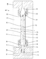
以下、本発明を具体化した実施形態1を図1乃至図6を参照して説明する。まず、二液混合装置Mについて説明すると、基台10の両端には一対の支持部12A,12Bが設けらられ、この支持部12A,12Bの間に円筒形をなす大径管13が差し渡されている。上流側(図1における左側)の支持部12A内には、下流側に向かって開口する流入室14が形成されているとともに、流入室14に連通する主剤流入孔15が形成されている。流入室14の奥端部には筒体16がねじ込みにより固着され、支持体12Aには、筒体16に連通する硬化剤流入孔17が形成されている。流入室14の開口縁部には、大径管13の上流側の端部が嵌合されナット18により固定されている。下流側の支持体12Bには、上流側に開口する流出室19が形成され、この流出室19に、大径管13の下流側の端部が嵌合されてナット20により固着されている。下流側の支持体12Bには、流出室19に連通する流出孔21が形成されている。
<Embodiment 1>
A first embodiment of the present invention will be described below with reference to FIGS. First, the two-component mixing apparatus M will be described. A pair of
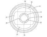
また、大径管13の中空内には同心円筒形をなす小径管22が収容されている。小径管22の上流側の端部は筒体16に固着され、これにより、小径管22は上流側の支持体12Aに片持ち状に支持されている。この小径管22の中空内は、硬化剤Lb(本発明の構成要件である第2液剤)が供給される硬化剤流路23(本発明の構成要件である第2流路)となっている。小径管22の下流端には閉止栓24が固着され、これにより、硬化剤流路23の下流端が閉塞されている。また、大径管13の中空内のうち小径管22を除いた領域(硬化剤流路23を包囲する空間)は、主剤La(本発明の構成要件である第1液剤)が供給される主剤流路25(本発明の構成要件である第1流路)となっている。
A small-
小径管22には、その内周面から外周面に貫通するオリフィス状の連通孔26が複数形成されており、この連通孔26により主剤流路25と硬化剤流路23が連通されている。連通孔26は、硬化剤流路23の上流端と下流端との間に適当な間隔を空けて一対ずつ形成され、対をなす連通孔26は小径管22の中心を挟んで互いに反対側に配置されている。また、小径管22の長さ方向(主剤La及び硬化剤Lbの流通方向)において隣り合う連通孔26対は、周方向において互いに向きが90°変わるような位置関係となっている。さらに、小径管22の外周には各連通孔26対と対応する障壁27が固着されている。障壁27は、主剤Laの流通方向に視て概ね長円形をなし、対応する連通孔26よりも上流側で且つ連通孔26の近傍に位置している。
A plurality of orifice-
上流側の支持体12Aの主剤流入孔15には、主剤Laの供給手段(図示せず)と、主剤Laを洗浄するための専用の洗浄液である水Wa(本発明の構成要件である第1洗浄液)の供給手段(図示せず)と、加圧空気を供給するためのエア供給手段(図示せず)とが接続され、主剤Laと水Waと加圧エアのいずれかが任意に供給されるようになっている。また、硬化剤流入孔17には、硬化剤Lbの供給手段(図示せず)と、硬化剤Lbを洗浄するための専用の洗浄液である溶剤Wb(本発明の構成要件である第2洗浄液)の供給手段(図示せず)と、加圧空気を供給するためのエア供給手段(図示せず)とが接続され、硬化剤Lbと溶剤Wbと加圧エアのいずれかが任意に供給されるようになっている。下流側の支持体の流出孔21には塗装ガン(図示せず)が接続されている。
In the main
塗装を行う際には、主剤Laを主剤流路25の上流端(主剤流入孔15)に供給するとともに、硬化剤Lbを硬化剤流路23の上流端(硬化剤流入孔17)に供給すると、硬化剤流路23内の硬化剤Lbが連通孔26を通って主剤流路25内に進入し、主剤流路25内において、主剤Laと硬化剤Lbが障壁27に突き当たって撹拌されつつ混合されて塗料となり、流出孔21から塗装ガンへ圧送される。尚、主剤Laの供給と硬化剤Lbの供給は、交互に行ってもよく、同時に行ってもよい。
When performing coating, when supplying the main agent La to the upstream end (main agent inflow hole 15) of the main
次に、塗装後に二液混合装置M内を洗浄する工程について説明する。
上記のように2種類の液剤(主剤Laと硬化剤Lb)を混合して得られる塗料として、本実施形態では、主剤La用の洗浄液と硬化剤Lb用の洗浄液が異なり、しかも一方の洗浄液が他方の液剤と接触するとその液剤が変質を来たすような組合せとなっている。即ち、本実施形態の塗料は、水性のエマルジョンからなる主剤Laとイソシアネートからなる硬化剤Lbとを混合して得られる水性ウレタン二液塗料であり、上記のように、主剤Laの洗浄液として水Waが用いられ、硬化剤Lbの洗浄液としてケトン、エステル系の溶剤Wbが用いられる。そのため、主剤Laを溶剤Wbで洗浄すると、主剤Laがエマルジョン破壊を来たして粘着性の高いゼリー状の物質に変化し、また、硬化剤Lbを水Waで洗浄すると、硬化剤Lbがやはりゼリー状の物質に変化する。このようにゼリー状に変質したものは、流路23,25の内壁に付着したり、流路23,25や連通孔26を詰まらせたりする等の不具合を来たす虞がある。本実施形態では、この点を充分考慮して洗浄が行われる。
Next, the process of cleaning the inside of the two-component mixing apparatus M after coating will be described.
As described above, as a paint obtained by mixing two types of liquid agents (main agent La and curing agent Lb), in this embodiment, the cleaning liquid for main agent La and the cleaning liquid for curing agent Lb are different, and one cleaning liquid is used. The combination is such that when the liquid is brought into contact with the other liquid, the liquid is altered. That is, the coating material of this embodiment is an aqueous urethane two-component coating material obtained by mixing a main agent La made of an aqueous emulsion and a curing agent Lb made of an isocyanate, and as described above, water Wa is used as a cleaning liquid for the main agent La. And a ketone or an ester solvent Wb is used as a cleaning liquid for the curing agent Lb. Therefore, when the main agent La is washed with the solvent Wb, the main agent La is broken into an emulsion and changed to a highly sticky jelly-like substance, and when the curing agent Lb is washed with water Wa, the curing agent Lb is still in the jelly-like state. The substance changes to. Such a jelly-like alteration may cause problems such as adhering to the inner walls of the
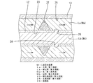
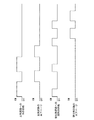
洗浄に際しては、図6のタイムチャートに示すように、まず、硬化剤流路23内に硬化剤Lbを残留させたままで、主剤流路25内に水Wa(主剤La専用の洗浄液)を供給し、この水Waの供給と同時に、硬化剤流路23内に溶剤Wb(硬化剤Lb専用の洗浄液)を供給する。塗装終了後は、主剤流路25内に主剤Laと硬化剤Lb若しくはその混合物(塗料)が残留しているが、これらは全て主剤流路25に供給される水Waによって洗い流されて主剤流路25の下流端から二液混合装置Mの外部へ排出される。この間、硬化剤流路23内は、溶剤Wbの供給によって加圧されるため、主剤流路25内に供給される水Waが硬化剤流路23内に浸入することはない(図3を参照)。したがって、硬化剤流路23内では硬化剤Lbが水Waとの接触に起因してゼリー状に変質することはない。
At the time of cleaning, as shown in the time chart of FIG. 6, first, water Wa (cleaning liquid dedicated to the main agent La) is supplied into the
また、硬化剤流路23内の硬化剤Lbや溶剤Wbが主剤流路25内に漏出したとしても、主剤流路25内では上流側から下流側に向かう流れが形成されているので、主剤流路25内に漏出した硬化剤Lbや溶剤Wb、及び硬化剤Lbと水Waとの接触により発生したゼリー状物質、溶剤Wbと主剤Laの接触により発生したゼリー状物質は、全て、主剤流路25の下流側に向かう流れに乗じて二液混合装置Mの外部へ排出される。
尚、本実施形態では、主剤流路25への水Waの供給と硬化剤流路23への溶剤Wbの供給はほぼ同時に開始されるが、溶剤Wbの供給は水Waの供給が継続している間に停止するが、この水Waと溶剤Wbの供給開始及び停止のタイミングは任意に設定することができる。
Even if the curing agent Lb and the solvent Wb in the
In this embodiment, the supply of the water Wa to the main
主剤流路25への水Waの供給が開始してから所定時間が経過すると、水Waの供給を停止し、その後、主剤流路25には加圧エアを供給する。この加圧エアにより、主剤流路25内に残留している液体が、加圧エアの圧力により二液混合装置M外へ排出される(図4を参照)。そして、このエアパージの工程の後、再び、主剤流路25内に水Waを供給し、主剤流路25の内壁(大径管13の内周面、小径管22の外周面、障壁27の表面)に付着、残留している液体を水Waの流れによって排出する。この間も、上記と同様に、硬化剤流路23内には溶剤Wbを供給し、硬化剤流路23内を加圧した状態とするので、水Waが硬化剤流路23内に浸入することはない。所定時間の経過後、主剤流路25への水Waの供給を停止すれば、主剤流路25内の主剤Laを排出する工程が完了する。
When a predetermined time has elapsed after the supply of water Wa to the main
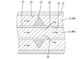
この後、硬化剤流路23内に溶剤Wbを供給する。すると、硬化剤流路23内の液体(硬化剤Lbと溶剤Wb)が、硬化剤流路23内を上流側から下流側に向かって流れつつ、連通孔26が主剤流路25内に進入し、主剤流路25内を上流側から下流側に向かって流れる(図5を参照)。このとき、主剤流路25内の主剤Laは上記工程において全て排出されているので、溶剤Wbと主剤Laの接触に起因してゼリー状物質が発生することはない。
Thereafter, the solvent Wb is supplied into the
溶剤Wbの供給開始から所定時間が経過すると、溶剤Wbの供給を停止し、その後、硬化剤流路23内に加圧エアを供給し、硬化剤流路23と主剤流路25内に残留している液体(硬化剤Lbと溶剤Wb)を加圧エアの圧力によって二液混合装置M外へ排出する。尚、硬化剤流路23に加圧エアを供給する間、主剤流路25に加圧エアを供給してもよい。
When a predetermined time has elapsed from the start of the supply of the solvent Wb, the supply of the solvent Wb is stopped, and then the pressurized air is supplied into the
このエアパージ工程の後、もう一度、硬化剤流路23内に溶剤Wbを供給し、主剤流路25の内壁(大径管13の内周面、小径管22の外周面、障壁27の表面)と硬化剤流路23の内壁(小径管22の内周面、連通孔26の内周面)に付着、残留している液体を溶剤Wbの流れによって排出する。そして、もう一度加圧エアを供給してエアパージを行えば、二液混合装置M内の洗浄が完了する。
After this air purge step, the solvent Wb is once again supplied into the
上述のように本実施形態においては、主剤流路25内の洗浄を行っている間、硬化剤流路23内を加圧して硬化剤流路23内の硬化剤Lbが主剤流路25内に浸入しないようにしているので、硬化剤流路23内において硬化剤Lbと水Waが接触することがなく、硬化剤流路23内で硬化剤Lbが変質することに起因する不具合を回避することができる。
As described above, in the present embodiment, while the
<他の実施形態>
本発明は上記記述及び図面によって説明した実施形態に限定されるものではなく、例えば次のような実施態様も本発明の技術的範囲に含まれ、さらに、下記以外にも要旨を逸脱しない範囲内で種々変更して実施することができる。
(1)上記実施形態では主剤を先に洗浄するようにしたが、本発明によれば。硬化剤を先に洗浄してもよい。
(2)上記実施形態では円形の硬化剤流路の外周を筒状の主剤流路が包囲する形態としたが、本発明によれば、円形の主剤流路の外周を筒状の硬化剤流路が包囲する形態としてもよい。
(3)上記実施形態では一方の流路の外周を筒状をなす他方の流路が包囲する形態としたが、本発明によれば、2本の流路が互いに横に並ぶように配索してもよい。
(4)上記実施形態では筒状の流路(主剤流路)に供給される液剤(主剤)を先に洗浄するようにしたが、本発明によれば、筒状の流路で包囲されている円形の流路に供給される液剤(主剤と硬化剤のいずれでもよい)を先に洗浄してもよい。この場合、円形の流路を塗装ガン側に連通させる。
(5)上記実施形態では水性のエマルジョンからなる主剤とイソシアネートからなる硬化剤を混合してウレタン塗料が得られる場合について説明したが、本発明は、主剤と硬化剤がこの以外の組合せであっても適用できる。
<Other embodiments>
The present invention is not limited to the embodiment described with reference to the above description and drawings. For example, the following embodiments are also included in the technical scope of the present invention, and further, within the scope not departing from the gist of the invention other than the following. Various modifications can be made.
(1) In the above embodiment, the main agent is washed first, but according to the present invention. The curing agent may be washed first.
(2) In the above embodiment, the outer periphery of the circular hardener flow path is surrounded by the cylindrical main agent flow path. However, according to the present invention, the outer periphery of the circular main agent flow path is surrounded by the cylindrical hardener flow path. It is good also as a form which a path surrounds.
(3) In the above embodiment, the outer periphery of one flow path is surrounded by the other flow path having a cylindrical shape. However, according to the present invention, the two flow paths are arranged side by side. May be.
(4) In the above embodiment, the liquid agent (main agent) supplied to the cylindrical flow path (main agent flow path) is washed first. However, according to the present invention, the liquid agent (main agent) is surrounded by the cylindrical flow path. The liquid agent (which may be either the main agent or the curing agent) supplied to the circular flow path may be washed first. In this case, the circular channel is connected to the coating gun side.
(5) In the above embodiment, the case where a urethane coating is obtained by mixing a main agent composed of an aqueous emulsion and a curing agent composed of an isocyanate has been described, but the present invention is a combination of the main component and the curing agent other than this. Is also applicable.
M…二液混合装置
La…主剤(第1液剤)
Lb…硬化剤(第2液剤)
Wa…水(第1洗浄液)
Wb…溶剤(第2洗浄液)
23…硬化剤流路(第2流路)
25…主剤流路(第1流路)
26…連通路
M ... Two-component mixing device La ... Main agent (first solution)
Lb ... Curing agent (second liquid)
Wa ... Water (first cleaning solution)
Wb ... Solvent (second cleaning liquid)
23 ... Curing agent channel (second channel)
25 ... Main agent flow path (first flow path)
26 ... Communication passage
Claims (1)
第2液剤が供給されるようになっており、下流側が閉塞された第2流路と、
前記第1流路と前記第2流路とを連通させる連通路とを備え、
前記第1液剤と前記第2液剤が夫々対応する前記流路の上流端に供給されると、前記第2流路内に供給された前記第2液剤が前記連通路を通って前記第1流路内に流入し、前記第1流路内において前記第1液剤と前記第2液剤とが下流側へ流れつつ混合されて前記塗装ガン側へ送出されるようになっており、
前記第1液剤用の第1洗浄液と前記第2液剤用の第2洗浄液とが互いに異なり、且つ一方の洗浄液が他方の液剤と接触したときにその液剤が変質を来たす組合せである前記第1液剤と前記第2液剤の混合に用いられた二液混合装置を洗浄する方法であって、
前記第1流路に前記第1洗浄液を流通させることで、前記第1流路内の前記第1液剤を排出し、
前記第1流路に前記第1洗浄液が流通されている間、前記第2流路に前記第2液剤又は前記第2洗浄液を供給して前記第2流路内を加圧することで、前記第1流路内の第1液剤及び前記第2洗浄液が前記第2流路へ浸入するのを規制し、
前記第1流路内の前記第2洗浄液をエアパージにより排出した後、前記第2流路内に前記第2洗浄液を供給することで、前記第2流路内の前記第2液剤を排出し、
前記第2流路内の前記第2洗浄液をエアパージにより排出することを特徴とする二液混合装置の洗浄方法。 A first flow path in which the first liquid agent is supplied and the downstream side communicates with the coating gun side;
A second liquid agent is supplied, and a second flow path whose downstream side is blocked;
A communication path for communicating the first flow path and the second flow path;
When the first liquid and the second liquid are respectively supplied to the upstream ends of the corresponding flow paths, the second liquid supplied in the second flow path passes through the communication path and the first flow. Flowing into the passage, the first liquid agent and the second liquid agent are mixed while flowing downstream in the first flow path, and sent to the coating gun side,
The first liquid agent is a combination in which the first cleaning liquid for the first liquid agent and the second cleaning liquid for the second liquid agent are different from each other, and when one of the cleaning liquids comes into contact with the other liquid agent, the liquid agent changes in quality. And a method of washing the two-component mixing apparatus used for mixing the second liquid agent,
By allowing the first cleaning liquid to flow through the first flow path, the first liquid agent in the first flow path is discharged,
By supplying the second liquid agent or the second cleaning liquid to the second flow path and pressurizing the second flow path while the first cleaning liquid is flowing through the first flow path, Restricting the first liquid agent and the second cleaning liquid in one flow path from entering the second flow path;
After discharging the second cleaning liquid in the first flow path by air purge, by supplying the second cleaning liquid into the second flow path, the second liquid agent in the second flow path is discharged,
A cleaning method for a two-liquid mixing apparatus, wherein the second cleaning liquid in the second flow path is discharged by air purge.
Priority Applications (1)
| Application Number | Priority Date | Filing Date | Title |
|---|---|---|---|
| JP2004202374A JP2006021150A (en) | 2004-07-08 | 2004-07-08 | Method for cleaning device for mixing two kinds of liquids |
Applications Claiming Priority (1)
| Application Number | Priority Date | Filing Date | Title |
|---|---|---|---|
| JP2004202374A JP2006021150A (en) | 2004-07-08 | 2004-07-08 | Method for cleaning device for mixing two kinds of liquids |
Publications (2)
| Publication Number | Publication Date |
|---|---|
| JP2006021150A true JP2006021150A (en) | 2006-01-26 |
| JP2006021150A5 JP2006021150A5 (en) | 2007-08-02 |
Family
ID=35794806
Family Applications (1)
| Application Number | Title | Priority Date | Filing Date |
|---|---|---|---|
| JP2004202374A Pending JP2006021150A (en) | 2004-07-08 | 2004-07-08 | Method for cleaning device for mixing two kinds of liquids |
Country Status (1)
| Country | Link |
|---|---|
| JP (1) | JP2006021150A (en) |
Cited By (3)
| Publication number | Priority date | Publication date | Assignee | Title |
|---|---|---|---|---|
| JP2007275844A (en) * | 2006-04-11 | 2007-10-25 | Asahi Sunac Corp | Mixing device |
| JP2009136743A (en) * | 2007-12-05 | 2009-06-25 | Asahi Sunac Corp | Paint feeding device and its cleaning method |
| JP2010082592A (en) * | 2008-10-01 | 2010-04-15 | Asahi Sunac Corp | Paint feeding device and its cleaning process |
Citations (4)
| Publication number | Priority date | Publication date | Assignee | Title |
|---|---|---|---|---|
| JPH0474553A (en) * | 1990-07-16 | 1992-03-09 | Aica Kogyo Co Ltd | Cleaning device for two liquid mixing and discharging machine |
| JPH11347460A (en) * | 1998-06-03 | 1999-12-21 | Asahi Sunac Corp | Two-pack mixing device |
| JP2000210616A (en) * | 1999-01-21 | 2000-08-02 | Sk Kaken Co Ltd | Formation of moisture permeable coating film |
| JP2004141800A (en) * | 2002-10-25 | 2004-05-20 | Honda Motor Co Ltd | Two-liquid mixing coating device |
-
2004
- 2004-07-08 JP JP2004202374A patent/JP2006021150A/en active Pending
Patent Citations (4)
| Publication number | Priority date | Publication date | Assignee | Title |
|---|---|---|---|---|
| JPH0474553A (en) * | 1990-07-16 | 1992-03-09 | Aica Kogyo Co Ltd | Cleaning device for two liquid mixing and discharging machine |
| JPH11347460A (en) * | 1998-06-03 | 1999-12-21 | Asahi Sunac Corp | Two-pack mixing device |
| JP2000210616A (en) * | 1999-01-21 | 2000-08-02 | Sk Kaken Co Ltd | Formation of moisture permeable coating film |
| JP2004141800A (en) * | 2002-10-25 | 2004-05-20 | Honda Motor Co Ltd | Two-liquid mixing coating device |
Cited By (3)
| Publication number | Priority date | Publication date | Assignee | Title |
|---|---|---|---|---|
| JP2007275844A (en) * | 2006-04-11 | 2007-10-25 | Asahi Sunac Corp | Mixing device |
| JP2009136743A (en) * | 2007-12-05 | 2009-06-25 | Asahi Sunac Corp | Paint feeding device and its cleaning method |
| JP2010082592A (en) * | 2008-10-01 | 2010-04-15 | Asahi Sunac Corp | Paint feeding device and its cleaning process |
Similar Documents
| Publication | Publication Date | Title |
|---|---|---|
| JP4750803B2 (en) | Rotary atomizing head type coating equipment | |
| JP2006021150A (en) | Method for cleaning device for mixing two kinds of liquids | |
| JP2009142806A (en) | Dispensing device having stirring function | |
| JP4804527B2 (en) | Nozzle for generating fine bubbles | |
| JP2007142133A (en) | Resist dilution system | |
| US20230029407A1 (en) | Cleaning device for cleaning a nozzle applicator and corresponding cleaning method | |
| JP5302561B2 (en) | Mixing device for paint supply equipment for multi-component coating | |
| JP2009136743A (en) | Paint feeding device and its cleaning method | |
| JP2011115735A (en) | Nozzle for drying inner surface of steel pipe for oil well pipe | |
| JP2010042360A (en) | Rotary atomizing head type coating device | |
| JP2007044631A (en) | Method of supplying aqueous two-liquid urethane coating material | |
| JP2003033910A (en) | Mixer for two-part curing type resin | |
| JP7202647B2 (en) | Porous nozzle and spraying method | |
| JP2007144289A (en) | Coating apparatus and method for washing the same | |
| JP6177381B2 (en) | nozzle | |
| JP5248258B2 (en) | Paint supply apparatus and cleaning method thereof | |
| JP4984655B2 (en) | Two-component mixing discharge device | |
| KR101874478B1 (en) | Two-component type of liquid fast-acting water repellent spraying device | |
| JP4373398B2 (en) | Injection disperser | |
| JP6810549B2 (en) | Paint gun cleaning device | |
| JP4882325B2 (en) | Ink supply path cleaning method and cleaning apparatus | |
| JP2007007533A (en) | Coater | |
| JP2014157911A (en) | Rotary coating apparatus and cleaning method of the same | |
| JP4481678B2 (en) | Application nozzle | |
| JP2009136840A (en) | Multi-liquid mixing device |
Legal Events
| Date | Code | Title | Description |
|---|---|---|---|
| RD04 | Notification of resignation of power of attorney |
Free format text: JAPANESE INTERMEDIATE CODE: A7424 Effective date: 20061201 |
|
| A521 | Written amendment |
Free format text: JAPANESE INTERMEDIATE CODE: A523 Effective date: 20070618 |
|
| A621 | Written request for application examination |
Free format text: JAPANESE INTERMEDIATE CODE: A621 Effective date: 20070618 |
|
| RD02 | Notification of acceptance of power of attorney |
Free format text: JAPANESE INTERMEDIATE CODE: A7422 Effective date: 20090907 |
|
| RD04 | Notification of resignation of power of attorney |
Free format text: JAPANESE INTERMEDIATE CODE: A7424 Effective date: 20090907 |
|
| A977 | Report on retrieval |
Free format text: JAPANESE INTERMEDIATE CODE: A971007 Effective date: 20100301 |
|
| A131 | Notification of reasons for refusal |
Free format text: JAPANESE INTERMEDIATE CODE: A131 Effective date: 20100817 |
|
| A02 | Decision of refusal |
Effective date: 20101214 Free format text: JAPANESE INTERMEDIATE CODE: A02 |