JP2005530606A - Equipment for coating and drying the front and back of webs, in particular webs made of paper or cardboard - Google Patents
Equipment for coating and drying the front and back of webs, in particular webs made of paper or cardboard Download PDFInfo
- Publication number
- JP2005530606A JP2005530606A JP2004514790A JP2004514790A JP2005530606A JP 2005530606 A JP2005530606 A JP 2005530606A JP 2004514790 A JP2004514790 A JP 2004514790A JP 2004514790 A JP2004514790 A JP 2004514790A JP 2005530606 A JP2005530606 A JP 2005530606A
- Authority
- JP
- Japan
- Prior art keywords
- coating
- material web
- drying
- application
- web
- Prior art date
- Legal status (The legal status is an assumption and is not a legal conclusion. Google has not performed a legal analysis and makes no representation as to the accuracy of the status listed.)
- Pending
Links
Images


Classifications
-
- D—TEXTILES; PAPER
- D21—PAPER-MAKING; PRODUCTION OF CELLULOSE
- D21H—PULP COMPOSITIONS; PREPARATION THEREOF NOT COVERED BY SUBCLASSES D21C OR D21D; IMPREGNATING OR COATING OF PAPER; TREATMENT OF FINISHED PAPER NOT COVERED BY CLASS B31 OR SUBCLASS D21G; PAPER NOT OTHERWISE PROVIDED FOR
- D21H23/00—Processes or apparatus for adding material to the pulp or to the paper
- D21H23/02—Processes or apparatus for adding material to the pulp or to the paper characterised by the manner in which substances are added
- D21H23/22—Addition to the formed paper
- D21H23/70—Multistep processes; Apparatus for adding one or several substances in portions or in various ways to the paper, not covered by another single group of this main group
- D21H23/72—Plural serial stages only
-
- D—TEXTILES; PAPER
- D21—PAPER-MAKING; PRODUCTION OF CELLULOSE
- D21H—PULP COMPOSITIONS; PREPARATION THEREOF NOT COVERED BY SUBCLASSES D21C OR D21D; IMPREGNATING OR COATING OF PAPER; TREATMENT OF FINISHED PAPER NOT COVERED BY CLASS B31 OR SUBCLASS D21G; PAPER NOT OTHERWISE PROVIDED FOR
- D21H19/00—Coated paper; Coating material
- D21H19/80—Paper comprising more than one coating
- D21H19/84—Paper comprising more than one coating on both sides of the substrate
Landscapes
- Coating Apparatus (AREA)
- Paper (AREA)
- Drying Of Solid Materials (AREA)
- Application Of Or Painting With Fluid Materials (AREA)
- Cleaning Implements For Floors, Carpets, Furniture, Walls, And The Like (AREA)
Abstract
Description
本発明は、コーティング/乾燥装置に関するもので、該装置は、走行方向に移動する材料ウェブ、特に紙または厚紙、の第1面に液体またはペースト状の塗布媒体を塗布する第1塗布装置を有し、第1面とは反対側の材料ウェブの第2面に液体またはペースト状の塗布媒体を塗布する第2塗布装置を有し、乾燥装置を有する。 The present invention relates to a coating / drying device, which has a first application device for applying a liquid or paste-like application medium on a first surface of a material web that moves in the direction of travel, in particular paper or cardboard. And it has the 2nd coating device which apply | coats a liquid or a paste-form application medium to the 2nd surface of the material web on the opposite side to a 1st surface, and has a drying apparatus.
このタイプのコーティング/乾燥装置は、先行技術において周知である。これらの装置では、通常、塗布媒体の層は材料ウェブの片面に塗布され、次に乾燥装置の中で乾燥される。その後ようやく材料ウェブのもう一方の面に塗布媒体層が塗布され、同様に乾燥される。こうしたコーティング/乾燥装置の欠点は、第1に、2つの乾燥装置を備えなければならない点で、これは、これらの乾燥装置の購入および維持に関して費用がかかるだけでなく、さらに、より多くの全空間を必要とする。第2に、片面乾燥のエネルギー効率、すなわち適用されるエネルギーの単位当りの乾燥効果には、多くの要求すべき点を残している。 This type of coating / drying apparatus is well known in the prior art. In these devices, a layer of coating medium is usually applied to one side of the material web and then dried in a drying device. Only then is the coating medium layer applied to the other side of the material web and dried as well. The disadvantage of such a coating / drying device is that, firstly, it must be equipped with two drying devices, which is not only expensive for the purchase and maintenance of these drying devices, but also more Requires space. Second, the energy efficiency of single-sided drying, that is, the drying effect per unit of energy applied, leaves many points to be demanded.
これに対して、本発明の目的は、材料ウェブの両面のコーティングおよび乾燥を省空間的かつ省エネルギー的方法で可能にする、冒頭で述べたタイプのコーティング/乾燥装置を提供することである。 In contrast, an object of the present invention is to provide a coating / drying device of the type mentioned at the outset, which makes it possible to coat and dry both sides of a material web in a space-saving and energy-saving manner.
本発明によると、この目的は汎用タイプのコーティング/乾燥装置によって達成され、該装置における第2塗布装置は非接触で作動する塗布装置であり、また該装置における乾燥装置は材料ウェブの走行方向において2つの塗布装置の下流に配置される。本発明によると、従って、中間乾燥は行われず、換言すれば第1塗布装置の位置と第2塗布装置の位置との間に設けられる乾燥装置はない。これにより、第1に、そうでなければ第2乾燥装置用に要する全空間を省き、第2に、第2乾燥装置の購入および維持に要する費用を節約する。さらに、乾燥装置によりもたらされる熱は、1つの湿った塗布媒体層で吸収されるだけでなく、2つの湿った塗布媒体層で吸収できる。熱吸収は、結果としてより高い効率となり、先行技術によるコーティング/乾燥装置と比較した場合、本発明によるコーティング/乾燥装置のエネルギー効率を向上させる。 According to the invention, this object is achieved by a general-purpose type coating / drying device, in which the second coating device is a non-contact operating coating device, and the drying device in the device is in the direction of travel of the material web. Located downstream of the two applicators. According to the present invention, therefore, intermediate drying is not performed, in other words, there is no drying device provided between the position of the first coating device and the position of the second coating device. This saves firstly all the space otherwise required for the second drying device and secondly saves the costs required to purchase and maintain the second drying device. Furthermore, the heat provided by the drying device can be absorbed not only by one wet application medium layer but also by two wet application medium layers. Heat absorption results in higher efficiency and improves the energy efficiency of the coating / drying device according to the invention when compared to the coating / drying device according to the prior art.
本発明の別の態様によると、汎用タイプのコーティング/乾燥装置について、2つの塗布装置を材料ウェブの走行方向においてほぼ同じ位置に配置し、乾燥装置を材料ウェブの走行方向において2つの塗布装置の下流に配置することが提案される。塗布装置は、少なくとも1つ、好ましくは両方を、非接触で作動する塗布装置として有利に設計することとができる。しかし、少なくとも1つの塗布装置が、塗布媒体層の形で塗布媒体を搬送する移送要素、好ましくは移送ローラ、の移送表面を用いて、間接的に塗布媒体を移送する塗布装置となる場合を除外するものではない。 According to another aspect of the present invention, for a general-purpose type coating / drying device, the two applicators are arranged at substantially the same position in the direction of travel of the material web, and the drying devices are arranged in the direction of travel of the material web. It is proposed to arrange downstream. At least one, and preferably both, of the applicator can be advantageously designed as an applicator operating in a non-contact manner. However, this excludes the case where at least one coating device becomes a coating device for transporting the coating medium indirectly using the transport surface of a transport element, preferably a transport roller, which transports the coating medium in the form of a coating medium layer. Not what you want.
第2の態様によるコーティング/乾燥装置の本発明による構成を用いると、材料ウェブの両面がコーティングされる場合に中間乾燥を省くことが同様に可能で、2つの塗布装置の配置が材料ウェブの走行方向においてほぼ同じ位置の場合、この中間乾燥の省略は、適切な場合材料ウェブに余分に塗布する、接触塗布にも全く適合する。 With the arrangement according to the invention of the coating / drying device according to the second aspect, it is likewise possible to dispense with intermediate drying when both sides of the material web are coated, the arrangement of the two applicators being the running of the material web In the case of approximately the same position in the direction, this omission of intermediate drying is also perfectly compatible with contact application, where appropriate applying extra to the material web.
既述の非接触塗布装置は、実質的に余分なく塗布媒体を材料ウェブに塗布する(「1対1塗布」)。従って、過剰塗布媒体の余分をかき取る必要はなく、材料ウェブとの物理的接触は起こらない。この結果、非接触塗布装置は材料ウェブに対して低い応力しか加えず、具体的には、塗布媒体に含まれる液体による材料ウェブの軟化によってもたらされるだけである。使用される非接触塗布装置としては、例えば、スプレー塗布装置、あるいはカーテン塗布装置も可能である。 The described non-contact application device applies the application medium to the material web with substantially no excess (“one-to-one application”). Therefore, there is no need to scrape off excess coating media and no physical contact with the material web occurs. As a result, the non-contact applicator applies only a low stress to the material web, in particular only due to the softening of the material web by the liquid contained in the application medium. As the non-contact coating device used, for example, a spray coating device or a curtain coating device is also possible.
原理的には、第1塗布装置は材料ウェブと接触してコーティングする塗布装置にすることも可能で、例えばブレード塗布装置という、塗布媒体の塗布層を平坦化するおよび/または調量するドクターブレードを有する塗布装置や、フィルム塗布装置という、材料ウェブが2つのローラの間に形成されたロール間隙を通って走行し、このロール間隙の中で、ローラの1つの表面に塗布された塗布媒体のフィルムと接触するに至る塗布装置、等の塗布装置が考えられる。しかし、本発明によると、第1塗布装置も、非接触で作動する塗布装置、例えばカーテン塗布装置、であると好ましい。これに関連した材料ウェブの低い応力は、本発明に関しては重要で、特に、本発明によると、材料ウェブは2つの塗布装置の間の中間乾燥装置での湿気の回収を行うことでの中間圧密を経験しないからである。 In principle, the first applicator can also be an applicator for coating in contact with the material web, for example a blade applicator, a doctor blade for flattening and / or metering the application layer of the application medium The material web travels through a roll gap formed between two rollers, such as a coating device or a film coating device, and in this roll gap, a coating medium applied to one surface of the roller. A coating device such as a coating device that comes into contact with the film is conceivable. However, according to the present invention, the first coating device is also preferably a coating device that operates in a non-contact manner, such as a curtain coating device. The low stress of the material web associated with this is important for the present invention, in particular according to the present invention the material web is subjected to intermediate consolidation by performing moisture recovery in an intermediate dryer between the two applicators. It is because it does not experience.
コーティング/乾燥装置の配置にとって利用可能な全空間および他の境界条件次第では、少なくとも1つのカーテン塗布装置は、塗布媒体を材料ウェブに上から重力によって塗布することができる。しかし、これに加えてまたは別の方法として、少なくとも1つのカーテン塗布装置に偏向装置を割り当てることも可能で、この偏向装置は、カーテン塗布装置からの塗布媒体カーテンを、重力による進路から偏向させる。塗布媒体カーテンの偏向は、例えば、塗布媒体カーテン内の塗布媒体と偏向装置との間に発生する静電気および/または電磁気の相互作用を基にすることができる。静電気および/または電磁気で作動するこのタイプの偏向装置は、先行技術において周知であり、従ってここではこれ以上の詳細については説明しない。 Depending on the total space available for the coating / drying device arrangement and other boundary conditions, at least one curtain applicator can apply the application medium to the material web from above by gravity. However, in addition or as an alternative, it is also possible to assign a deflection device to at least one curtain coating device, which deflects the coating medium curtain from the curtain coating device from the path of gravity. The deflection of the application medium curtain can be based, for example, on electrostatic and / or electromagnetic interactions that occur between the application medium in the application medium curtain and the deflection device. This type of deflecting device that operates electrostatically and / or electromagnetically is well known in the prior art and will not be described in further detail here.
上記によると、両方のカーテン塗布装置からの塗布媒体カーテンを、偏向装置を用いて、重力によるそれぞれの進路から偏向させることも可能である。例示的ウェブ進路によると、材料ウェブはほぼ垂直に下から上に走行可能で、2つの塗布装置はそれぞれ材料ウェブのどちらか一方の面に配置され、2つの塗布媒体カーテンは、偏向装置を始動することで、そのままでは材料ウェブを湿らせるには至らない重力による進路から、材料ウェブを湿らせる作動進路へと偏向される。 According to the above, it is also possible to deflect the coating medium curtains from both curtain coating devices from their respective paths due to gravity using a deflection device. According to an exemplary web path, the material web can travel substantially vertically from bottom to top, the two applicators are each located on either side of the material web, and the two applicator media curtains start the deflection device By doing so, it is deflected from the path of gravity that does not wet the material web as it is, to the operating path that wets the material web.
特に両方の塗布媒体カーテンを偏向する場合、2つの塗布装置は材料ウェブの走行方向においてほぼ同じ位置に配置されると有利である。 Particularly when deflecting both coating medium curtains, it is advantageous if the two coating devices are arranged at approximately the same position in the direction of travel of the material web.
さらに、2つの塗布装置は、ほぼ垂直方向、好ましくは下から上、に走行する材料ウェブの切片上に配置されるよう提案される。ここで「ほぼ垂直方向に走行する」と言う場合、全体として、正確に垂直な進路に対するより大きい角度許容差、適切ならば±45度まで、を含む。しかし、正確に垂直な進路に対してはより小さい角度差、例えば±20度、の方がより適切であろう。 Furthermore, it is proposed that the two applicators be arranged on a section of the material web that runs in a substantially vertical direction, preferably from bottom to top. Reference to “running in a substantially vertical direction” herein includes, as a whole, a larger angular tolerance for a precisely vertical path, up to ± 45 degrees if appropriate. However, a smaller angular difference, for example ± 20 degrees, would be more appropriate for a precisely vertical path.
しかし、原理的には、第2塗布装置は、材料ウェブの走行方向において第1塗布装置から所定の距離をおいた下流に配置することもできる。例えば、2つの塗布装置は、塗布媒体の上からの塗布を可能にするために、ほぼ水平に走行する材料ウェブの走行部分の切片に配置することもできる。これは、特にカーテン塗布装置が使用される場合に有利である。この「上から」の塗布は、材料ウェブの正確に水平な進路から45度までの許容差があっても依然として容易に可能なので、「ほぼ水平な走行」という表現は、相当広く解釈される。 However, in principle, the second applicator can also be arranged downstream from the first applicator in the direction of travel of the material web. For example, the two applicators can also be arranged in a section of the traveling part of the material web that travels substantially horizontally to allow application from above the application medium. This is particularly advantageous when curtain applicators are used. Since this “from the top” application is still easily possible even with tolerances up to 45 degrees from the exact horizontal path of the material web, the expression “substantially horizontal travel” is interpreted fairly widely.
一つがもう一つの上にくる塗布装置の配置は、利用可能な全高を活用し、それによって全体長を節約するので、その結果として、例えば、ほぼ水平に走行する切片の間の材料ウェブは、少なくとも1つのウェブ偏向ユニットを用いて、ほぼ180度偏向される。「ほぼ180度偏向される」という表現もまた上記に従って広く解釈され、約140〜210度の偏向を対象として含むことができることは言うまでもない。 The arrangement of the applicator device, one on top of the other, takes advantage of the available height and thereby saves the overall length, so that, for example, the material web between sections running almost horizontally is It is deflected approximately 180 degrees using at least one web deflection unit. It will be appreciated that the expression “deflected approximately 180 degrees” is also broadly interpreted according to the above and can include deflections of approximately 140-210 degrees.
塗布されたばかりで、従って未だ湿っている塗布媒体層の表面特性に対して、湾曲したウェブ進路をもたらすウェブ偏向ユニットによるあらゆる影響を防止できるようにするために、第1塗布装置と第2塗布装置との間のウェブ偏向ユニットは、材料ウェブの未コーティングの第2面上に配置する、という対応がとられる。しかし、「エアターン」として知られる装置が使用される場合、換言すると、材料ウェブはこれら「エアターン」から放出される圧縮エアクッション上を非接触で誘導されるので、第1塗布装置と第2塗布装置との間のウェブ偏向ユニットは、原理的には、材料ウェブのコーティングされた第1面上に配置することもできる。 In order to be able to prevent any influence by the web deflection unit that provides a curved web path on the surface properties of the coating medium layer that has just been applied and is therefore still wet, the first coating device and the second coating device. The web deflection unit between the two is arranged on the second uncoated side of the material web. However, when a device known as an “air turn” is used, in other words, the material web is guided in a non-contact manner over the compressed air cushion released from these “air turns”, so that the first application device and the second application device The web deflection unit to and from the device can in principle also be arranged on the first coated surface of the material web.
最後に、さらにウェブターニング装置(web turning device)を、第1塗布装置と第2塗布装置との間に配置することも可能である。このウェブターニング装置の偏向ユニットの軸もしくはシャフトは、それぞれの偏向ユニットに向かって走行する材料ウェブのウェブ切片に対して平行に、かつ走行するウェブ切片の横方向に対して所定の角度で、伸びている。この接続では、「エアターン」もウェブ偏向ユニットとして使用することができる。これらは、例えば穴の空いたパイプとして、構成可能で、この穿孔は、圧縮ガスクッションを形成する圧縮ガスを放出するのに使用される。 Finally, it is also possible to arrange a web turning device between the first application device and the second application device. The axis or shaft of the deflection unit of this web turning device extends parallel to the web section of the material web traveling towards the respective deflection unit and at a predetermined angle with respect to the transverse direction of the traveling web section. ing. With this connection, an “air turn” can also be used as a web deflection unit. These can be configured, for example, as perforated pipes, and the perforations are used to release compressed gas that forms a compressed gas cushion.
しかし、2つの塗布装置の配置に関わらず、特に塗布媒体液滴等によってコーティング装置全体の汚染を防止するためには、2つの塗布装置を共通のハウジングに収容すると有利である。 However, regardless of the arrangement of the two applicators, it is advantageous to accommodate the two applicators in a common housing, in particular in order to prevent contamination of the entire coating apparatus by application medium droplets or the like.
本発明の発展形態では、さらに、第1塗布装置と乾燥装置との間の材料ウェブのウェブ走行部分の湾曲した切片は、少なくとも300mmの湾曲率の半径を有することが提案される。湾曲のこの最低半径が認められる場合のみ、ウェブ走行部分の湾曲した切片の領域で、未だ湿っている塗布層に作用する遠心力が、塗布媒体液滴が遠心力によって飛び散るのを防げるくらい弱くなる状態が確保される。このことは特に、1000m/分を超えるウェブ速度で当てはまる。 In a further development of the invention, it is further proposed that the curved section of the web running portion of the material web between the first application device and the drying device has a radius of curvature of at least 300 mm. Only when this minimum radius of curvature is observed, in the area of the curved section of the web running part, the centrifugal force acting on the still wet coating layer is weak enough to prevent the coating medium droplets from splashing by the centrifugal force. State is secured. This is especially true at web speeds in excess of 1000 m / min.
本発明によるコーティング/乾燥装置は、移動する材料ウェブを安定させるため、および/または、移動する材料ウェブのうねり、特に横方向のうねり、を回避もしくは軽減するために、少なくとも1つの非接触の装置を有利に備えることができる。例えば、少なくとも1つのコアンダ効果ノズル装置を有利に設けることができる。回避もしくは軽減すべきうねり、特に横方向のうねり、を打ち消す対抗するうねり、特に長手方向のうねり、を生成する少なくとも1つのノズル装置の使用も有効である。 The coating / drying device according to the invention comprises at least one non-contact device for stabilizing the moving material web and / or for avoiding or reducing the waviness of the moving material web, in particular the lateral waviness. Can be advantageously provided. For example, at least one Coanda effect nozzle device can be advantageously provided. It is also advantageous to use at least one nozzle device that produces a counter swell, especially a longitudinal swell, that counteracts the swell to be avoided or reduced, in particular the lateral swell.
さらに、本発明によるコーティング/乾燥装置は、移動する材料ウェブに沿って引きずられる空気境界層を破壊し、好ましくは除去あるいは軽減するための装置を、少なくとも1つ有利に備えることができる。この装置は、塗布媒体の塗布が空気境界層によって阻害されないよう、理想的には、それぞれの塗布装置の上流の近くもしくは直近に配置されるべきで、それによって高度な品質要求に見合ったコーティングが達成される。 Furthermore, the coating / drying device according to the invention can advantageously comprise at least one device for breaking, preferably removing or mitigating the air boundary layer dragged along the moving material web. This device should ideally be located near or close to the upstream of each application device so that the application of the application medium is not hindered by the air boundary layer, so that a coating that meets the high quality requirements can be achieved. Achieved.
本発明は、いくつかの例示的実施形態について、添付の図面を参照しつつ、以下の記述においてより詳細に説明される。 The present invention will be described in more detail in the following description, with reference to the accompanying drawings, for several exemplary embodiments.
図1では、本発明によるコーティング/乾燥装置を全体として10で示す。この装置は、走行方向Lに移動する材料ウェブ12の第1面12aに塗布媒体の第1層を塗布する第1塗布装置14と、面12aの反対側の材料ウェブ12の面12bに塗布媒体の第2層を塗布する第2塗布装置16と、材料ウェブ12の走行方向Lにおいて2つの塗布装置14および16の下流に配置された乾燥装置18と、を備えている。本発明によると、2つの塗布装置14および16の間を走行するウェブに対しては、別の乾燥装置はない。つまり、材料ウェブ12は、塗布装置14と塗布装置16との間で中間乾燥されることはない。
In FIG. 1, a coating / drying apparatus according to the present invention is indicated generally at 10. This device includes a first coating device 14 for applying a first layer of a coating medium on a first surface 12a of a
図1に示すとおり、本例示的実施形態における両塗布装置14および16は、カーテン塗布装置として構成されており、換言すれば、装置内部で塗布媒体が自給式塗布媒体カーテンとして塗布装置のノズルから出て、外部からの力、特に重力の影響を受けて材料ウェブ12に向けて自由空間を通って移動する塗布装置である。この材料ウェブ12に対する塗布媒体の非接触式塗布により、材料ウェブ12には確実にわずかしか応力がかからない。特に、材料ウェブと塗布装置の要素、例えばドクターブレード等、との間の物理的相互作用の結果として起こる損傷の危険性がない。しかし原理的には、塗布装置14、16はスプレー塗布装置として構成することも可能である。
As shown in FIG. 1, both
さらに、2つの塗布装置14、16は、材料ウェブ12の進路でほぼ水平に伸びる切片12’および12’’に配置され、材料ウェブ12に対してほぼ上から塗布媒体を塗布することは注目すべきである。この配置を可能にするために、図1によると、偏向ローラ20が設けられ、2つの塗布装置14と16との間の材料ウェブ12を偏向させる。図1による例示的実施形態のこれら偏向ローラ20は、両方とも材料ウェブ12の未コーティング面12b上に配置されるので、塗布装置14によって材料ウェブ12の面12aに塗布された層を損なわずにすむ。これに加えて、2つの偏向ローラ20は、比較的大きい直径を有するので、材料ウェブ12を偏向する間、塗布装置14によって材料ウェブ12に塗布された層には弱い遠心力しかかからない。
It is further noted that the two
最後に、非接触で作動する偏向装置22も、塗布装置16と乾燥装置10との間に配置される。この偏向装置22は、例えば「エアターン」として知られる装置による形成が可能で、圧縮エアクッションの上で非接触で材料ウェブ12を誘導する。
Finally, a deflecting
本発明によるコーティング/乾燥装置の別の実施形態で、図1による実施形態にほぼ一致するものを、図2に示す。従って、図2では、類似部分には図1と同じ符号表示で、但し100を足した数字が示されている。さらに、図2による実施形態については、図1による実施形態と異なり、図1の説明が別の方法でここに特に示される点についてのみ、以下の本文で述べる。 Another embodiment of the coating / drying device according to the invention, which corresponds approximately to the embodiment according to FIG. 1, is shown in FIG. Accordingly, in FIG. 2, similar parts are indicated by the same reference numerals as in FIG. Furthermore, the embodiment according to FIG. 2 differs from the embodiment according to FIG. 1 only in that the description of FIG. 1 is otherwise indicated here in the following text.
図2によるコーティング/乾燥装置110は、第1カーテン塗布装置114と第2カーテン塗布装置116との間で材料ウェブ112を偏向させる偏向ローラ120の構造に関してのみ、図1によるコーティング/乾燥装置10とは異なる。具体的には、図2による偏向ローラ120は、最初にコーティングされた材料ウェブ112の面112a上に配置される。従ってそれらは、非接触の偏向装置、例えば「エアターン」として知られる装置、として構成され、図1による実施形態を参照して、偏向装置22の例を使用して説明したとおりである。図2による実施形態でもまた、非接触で作動する偏向装置122が、材料ウェブ112の第2面112bをコーティングする塗布装置116と乾燥装置118との間に設けられる。
The coating / drying device 110 according to FIG. 2 is different from the coating /
本発明によるコーティング/乾燥装置の別の実施形態で、図1にほぼ一致するものを、図3に示す。従って、図3では、類似部分には図1と同じ符号表示で、但し200を足した数字が示されている。さらに、図3による実施形態については、図1による実施形態と異なり、図1の説明が別の方法でここに特に示される点についてのみ、以下の本文で述べる。 Another embodiment of the coating / drying apparatus according to the present invention, which corresponds approximately to FIG. 1, is shown in FIG. Therefore, in FIG. 3, the similar parts are indicated by the same reference numerals as in FIG. Furthermore, the embodiment according to FIG. 3 differs from the embodiment according to FIG. 1 only in that the description of FIG.
図3によるコーティング/乾燥装置210では、2つのカーテン塗布装置214および216は、ほぼ下から上に移動する材料ウェブ212のどちらか一方の面の上に配置される。概略的に明示されている偏向装置224を用いて、2つの塗布装置214および216からの2つの塗布媒体カーテン214aおよび216bは、図3に破線で示される純粋に重力による進路から、材料ウェブ212の表面212aおよび212bを湿らせる進路に偏向する。偏向装置224は、例えば塗布媒体との静電気相互作用に基づいて、作動することができる。
In the coating / drying device 210 according to FIG. 3, the two
本発明によるコーティング/乾燥装置の別の実施形態で、図1にほぼ一致するものを、図4に示す。従って、図4では、類似部分には図1と同じ符号表示で、但し300を足した数字が示されている。さらに、図4による実施形態については、図1による実施形態と異なり、図1の説明が別の方法でここに特に示される点についてのみ、以下の本文で述べる。 Another embodiment of the coating / drying apparatus according to the present invention, which corresponds approximately to FIG. 1, is shown in FIG. Therefore, in FIG. 4, similar parts are indicated by the same reference numerals as in FIG. Furthermore, the embodiment according to FIG. 4 differs from the embodiment according to FIG. 1 only in that the description of FIG.
図4によるコーティング/乾燥装置310は、第1カーテン塗布装置314と第2カーテン塗布装置316との間で材料ウェブ312が偏向される方法についてのみ、図1および図2による実施形態と異なり、具体的には、図3によると、ウェブターニング装置326がこのために使用される。このウェブターニング装置326の偏向ユニット328の軸もしくはシャフト328aは、各偏向ユニット328へと走行する材料ウェブ12のウェブ切片に平行に伸び、かつウェブ切片が走行する縦方向Qに対しては所定の角度で伸びている。
The coating / drying device 310 according to FIG. 4 differs from the embodiment according to FIGS. 1 and 2 only in the way in which the material web 312 is deflected between the first
これらの軸もしくはシャフトはパイプとして構成され、多数の開口部を有し、圧縮空気供給源と連動して、ウェブを搬送するエアクッションを形成する。 These shafts or shafts are configured as pipes, have a large number of openings, and cooperate with a compressed air supply source to form an air cushion for conveying the web.
図5は、製紙機械の乾燥部440の下流に接続された本発明によるコーティング装置410を示す。移動する材料ウェブ412は、ガイドローラ442を用いて行われるウェブの偏向によって、上からコーティング装置(塗工機)の中へ導かれる。第1カーテン塗布装置414および第2カーテン塗布装置416の下でのウェブ誘導装置のさらに進んだ進路は、図1の例示的実施形態にほぼ一致する。使用は2つの偏向ローラ420で形成される。しかし、各塗布装置の上流では、移動材料ウェブによって引きずられる空気境界層を除去あるいは少なくとも軽減するために、好ましくは、例えば吸引ボックス444または446のような要素が設けられる。
FIG. 5 shows a
双方向矢印で示されるように、2つの塗布装置414および416は、好ましくは垂直に調節できる。材料ウェブは各塗布装置414もしくは416と溝槽448もしくは450との間を通って走行し、この溝槽は過剰な塗布媒体を回収する。
As indicated by the double arrows, the two
第2塗布装置の下を通過した後、材料ウェブ412はエアターン422の上を非接触で作動する乾燥装置(図示せず)へと導かれる。例えば、熱風乾燥機を設けることもできる。エアターン422の代わりに、あるいはそれに加えて、エアノズル452によって誘導装置をさらに設けることもできる。エアノズルを通る材料ウェブの例示的進路は、破線(412’)で示される。移動する材料ウェブにおいて、波の底と波の頂点が材料ウェブの走行方向もしくは長手方向に交互に続く軽いうねりが生成されるにように、エアノズルを配置することができ、このうねりは波の頂点と波の底が横方向に交互に続く材料ウェブの望ましくない横方向のうねりを打ち消す。
After passing under the second application device, the
偏向ローラ420について、塗布媒体(コーティング色素)が外れるのを避けるため、比較的大きい、例えば600mmより大きい、直径を有するローラについてまず検討する。
For the
図から明らかにわかるとおり、本発明によると、第1塗布装置414による塗布と、第2塗布装置416による塗布との間には、材料ウェブの中間乾燥は用意されていない。図5に従って実施されるウェブ誘導装置の図の重要な点は、それぞれにコーティングされたウェブ面は、十分な乾燥が完了するまで、どのウェブガイドローラもしくはそれに類するものにも接触しないということである。
As can be clearly seen from the figure, according to the present invention, there is no intermediate drying of the material web between the application by the
図6による配置では、コーティング/乾燥装置は、同様に製紙機械の乾燥部540の下流に接続される。材料ウェブ512は下からコーティング装置の中へ導かれ、続いて複数のガイドローラを用いて機械の走行方向と逆向きにウェブの偏向が行われる。第1塗布装置514は、好ましくは、上流に接続された空気境界層を取り去るあるいは避けるための要素、例えば吸引ボックス544のような要素を有する。材料ウェブ512は、図2による配置と同様の方法で、2つのエアターン520を用いて偏向されるので、材料ウェブは再び機械の走行方向に偏向される。再び機械の走行方向に移動する材料ウェブ切片に対して、第2塗布装置516が塗布を行う。好ましくは、空気境界層を取り去る/避ける要素546が第2塗布装置516の上流にさらに接続される。
In the arrangement according to FIG. 6, the coating / drying device is likewise connected downstream of the
2つのエアターン520は、第1塗布装置514によってコーティングされた材料ウェブの面の上で、ガイドエアを用いて作用する。安定した材料ウェブ誘導装置を確保するために、材料ウェブのもう一方の未だコーティングされていない面に、1つ以上の支持ローラを割り当てることが可能である。材料ウェブは、好ましくはカーテン塗布装置として設計される第2塗布装置516の下を通過した後、第1塗布装置514と全く同様に、安定化のために使用されるエアノズル552を通って走行する。その後別のエアターン522によって非接触乾燥装置518の中へと偏向され、その下流には通常の乾燥部門の方法で接触して作動する別の乾燥装置560が接続できる。
The two air turns 520 act with guide air on the surface of the material web coated by the
各コーティング/乾燥装置に供給される材料ウェブは、図5および図6によると、最初に下面が、その次に上面がコーティングされる。反対ももちろん可能で、すなわち上面が最初にコーティングされ、次に下面がコーティングされる。図5および6による両方の解決策は、前述の例示的実施形態の解決策と全く同様に、大変コンパクトであり、従って、また既存の図解における再構築手段としても適している。従来の解決策と(例えば、施工するのに好ましいカーテンコーティングの代わりとして、ブレードコーティングやフィルムコーティング等)比較して、十分に低い投資コストを想定することが可能であり、この低コストは特に中間乾燥を省くことで、またこれに関連したコンパクト性によって達成される。 According to FIGS. 5 and 6, the material web fed to each coating / drying device is first coated on the lower surface and then on the upper surface. The reverse is of course also possible, i.e. the top surface is coated first and then the bottom surface is coated. Both solutions according to FIGS. 5 and 6 are very compact, just like the solution of the exemplary embodiment described above, and are therefore also suitable as a reconstruction means in existing illustrations. Compared to conventional solutions (eg blade coating or film coating instead of the preferred curtain coating for construction), it is possible to envisage a sufficiently low investment cost, this low cost being especially intermediate This is achieved by eliminating drying and by the compactness associated with this.
図7によるコーティング/乾燥装置610は、図5による配置におおむね一致する。前述の例示的実施形態で今まで使用したように、類似または一致する構成要素には同一の符号表示が使用され、それぞれ100を加えた数字となる。機械走行方向とは逆向きの偏向をもたらす偏向ローラと、材料ウェブの下側用の第1カーテン塗布装置614で空気境界層の除去用に上流に接続した要素644(吸引ボックスの代わりに、例えばあるタイプのドクターブレードも適している)を備えたものと、再び機械の走行方向に偏向をもたらす偏向ローラ620と、第2カーテン塗布装置616で理想的には同様に空気境界層の除去用に上流に接続した要素646を備えたものと、エアターン622によって非接触乾燥装置618の中へ材料ウェブ612を誘導するさらなる誘導装置と、が参照できる。破線の円で示されたX領域には、コアンダ効果装置または安定化ノズル装置、例えば装置452または552に一致する装置、を適宜設けることができる。
The coating /
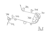
別の適切な配置を図8に示す。いずれの場合も、吸引ボックス744および746、または空気境界層の除去もしくは軽減用の別の要素が、カーテン塗布装置714および716の上流に接続されるのが好ましい。分割部分を備えた設計のエアターン装置720およびエアターン722はそれぞれ、第2カーテン塗布装置716および図示していない乾燥装置に向けて、非接触のウェブ偏向をもたらす。
Another suitable arrangement is shown in FIG. In either case,
図6の配置に非常に類似した配置を、図9に概略的に示す。図示された構成要素のタイプおよび機能は、図6で使用された符号表示に一致する符号表示によってそのまま示されている。エアターン722は、図5のように下向きではなく、材料ウェブ712を斜め上方向に偏向する。
An arrangement very similar to that of FIG. 6 is shown schematically in FIG. The type and function of the components shown are indicated as such by a symbolic representation that matches the symbolic representation used in FIG. The
カーテン塗布装置814および816を用いてコーティングフィルムがそれぞれローラに充填された、塗布ローラ860および862による両面への間接塗布を図10に示す。材料ウェブは、塗布ローラ460および462に属するロール間隙を通って走行する。従って、2つの塗布装置、片側の814、860と、もう一方の側の816、862とは、材料ウェブの走行方向において材料ウェブにとってほぼ同じ位置に配置される。カーテン塗布装置ヘッド814および816を用いてコーティングされるローラ表面には、好ましくはそれぞれに、空気境界層を除去するあるいは少なくとも軽減する要素で、例えばエアカットとして知られる、要素844および846が割り当てられる。相当する要素を、ロール間隙の中へと走行する材料ウェブの面に対して割り当てることもできる。
FIG. 10 shows indirect application on both sides by
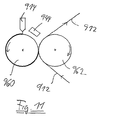
図10の配置に非常に類似しているが、材料ウェブ912が片側のみコーティングされる配置を、図11に示す。コーティングローラ960は、従って、1つの支持およびガイドローラ962にのみ割り当てられ、このガイドローラは材料ウェブ912を偏向させ、ローラ960と共にコーティングロール間隙を形成する。ローラ962から遠ざかる材料ウェブは、非接触の誘導装置によって、別の塗布装置、例えばカーテン塗布装置で、材料ウェブのもう一方の面をコーティングする装置、に供給することができる。
Although very similar to the arrangement of FIG. 10, an arrangement in which the
もう一度、構成要素または要素452、552および領域Xを参照し、さらに要素444、446、544、546、644、646、744、746、844、846、944を参照すると、価値の高いコーティング成果を得るには、うねりの回避、およびウェブ誘導装置の高度な安定性の達成、さらに塗布を阻害する空気境界層の回避または少なくとも軽減が、実践においては大変重要であることに注目すべきである。ウェブの安定化および阻害的うねりの回避のためには、既述のコアンダ効果エアノズル装置が有利で適しており、この装置は、真空の生成によって、ウェブ誘導装置を強制的に制御し、材料ウェブのあらゆるうねりを平坦化し、さらに既述の複数のノズルを有する塗布ノズル装置は、ウェブの異なる面上に走行方向に交互に配置され、所定の方法で材料ウェブに対し走行方向にうねりを与えて、このうねりが横方向の有害なうねりを打ち消す。
Referring once again to the components or
Claims (21)
前記第1面(12a)とは反対側の、前記材料ウェブ(12)の第2面(12b)に液体またはペースト状の塗布媒体を塗布する、第2塗布装置(16)と、
乾燥装置(18)とを有する、コーティング/乾燥装置(10)であって、
前記第2塗布装置(16)は非接触で作動する塗布装置であり、
前記乾燥装置(18)は前記材料ウェブ(12)の前記走行方向(L)において前記2つの塗布装置(14、16)の下流に配置されることを特徴とする装置。 A first application device (14) for applying a liquid or paste-like application medium to a first surface (12a) of a material web (12) moving in the running direction (L), in particular paper or cardboard;
A second application device (16) for applying a liquid or paste-like application medium to the second surface (12b) of the material web (12) opposite to the first surface (12a);
A coating / drying device (10) having a drying device (18),
The second coating device (16) is a coating device that operates without contact,
The drying device (18) is arranged downstream of the two coating devices (14, 16) in the running direction (L) of the material web (12).
前記第1面(212a)とは反対側の、前記材料ウェブ(212)の第2面(212b)に液体またはペースト状の塗布媒体を塗布する、第2塗布装置(216)と、
乾燥装置とを有する、コーティング/乾燥装置(210)であって、
前記2つの塗布装置(214、216)は前記材料ウェブ(212)の前記走行方向(L)においてほぼ同じ位置に配置され、
前記乾燥装置は前記材料ウェブ(212)の前記走行方向(L)において前記2つの塗布装置(214、216)の下流に配置されることを特徴とする装置。 A first application device (214) for applying a liquid or paste-like application medium to a first surface (212a) of a material web (212) moving in the running direction (L), in particular paper or cardboard;
A second application device (216) for applying a liquid or paste-like application medium to the second surface (212b) of the material web (212) opposite to the first surface (212a);
A coating / drying device (210) having a drying device,
The two applicators (214, 216) are arranged at approximately the same position in the travel direction (L) of the material web (212);
The drying device is arranged downstream of the two coating devices (214, 216) in the running direction (L) of the material web (212).
Applications Claiming Priority (2)
| Application Number | Priority Date | Filing Date | Title |
|---|---|---|---|
| DE10228114A DE10228114A1 (en) | 2002-06-24 | 2002-06-24 | Device for painting on both sides and for drying a material web, in particular made of paper or cardboard |
| PCT/EP2003/006479 WO2004001133A2 (en) | 2002-06-24 | 2003-06-18 | Device for coating and drying the front and back of a web, particularly one consisting of paper or cardboard |
Related Child Applications (1)
| Application Number | Title | Priority Date | Filing Date |
|---|---|---|---|
| JP2009219510A Division JP2010017711A (en) | 2002-06-24 | 2009-09-24 | Apparatus for coating and drying face and back of web, especially web made of paper or pasteboard |
Publications (1)
| Publication Number | Publication Date |
|---|---|
| JP2005530606A true JP2005530606A (en) | 2005-10-13 |
Family
ID=29723414
Family Applications (2)
| Application Number | Title | Priority Date | Filing Date |
|---|---|---|---|
| JP2004514790A Pending JP2005530606A (en) | 2002-06-24 | 2003-06-18 | Equipment for coating and drying the front and back of webs, in particular webs made of paper or cardboard |
| JP2009219510A Pending JP2010017711A (en) | 2002-06-24 | 2009-09-24 | Apparatus for coating and drying face and back of web, especially web made of paper or pasteboard |
Family Applications After (1)
| Application Number | Title | Priority Date | Filing Date |
|---|---|---|---|
| JP2009219510A Pending JP2010017711A (en) | 2002-06-24 | 2009-09-24 | Apparatus for coating and drying face and back of web, especially web made of paper or pasteboard |
Country Status (6)
| Country | Link |
|---|---|
| EP (1) | EP1516087B2 (en) |
| JP (2) | JP2005530606A (en) |
| CN (1) | CN100404758C (en) |
| AT (1) | ATE317927T1 (en) |
| DE (3) | DE20221952U1 (en) |
| WO (1) | WO2004001133A2 (en) |
Cited By (3)
| Publication number | Priority date | Publication date | Assignee | Title |
|---|---|---|---|---|
| JP2007169797A (en) * | 2005-12-19 | 2007-07-05 | Mitsubishi Heavy Ind Ltd | Apparatus for producing coated sheet and method for producing the same |
| KR101309343B1 (en) | 2010-09-24 | 2013-09-17 | 가부시끼가이샤 도시바 | Double side applying apparatus and double side applying method |
| WO2013183477A1 (en) * | 2012-06-04 | 2013-12-12 | 日東電工株式会社 | Coating device |
Families Citing this family (14)
| Publication number | Priority date | Publication date | Assignee | Title |
|---|---|---|---|---|
| DE10358508A1 (en) * | 2003-12-13 | 2005-07-07 | Voith Paper Patent Gmbh | applicator |
| DE102004004154A1 (en) * | 2004-01-28 | 2005-08-18 | Voith Paper Patent Gmbh | Application process |
| DE102008000160A1 (en) | 2008-01-28 | 2009-07-30 | Voith Patent Gmbh | Device for improving the working conditions of the operators of a coating device |
| DE102008041419A1 (en) * | 2008-08-21 | 2010-02-25 | Voith Patent Gmbh | Apparatus for producing coated paper, board or other fibrous webs with at least one thermosensitive layer and method for operating such a device |
| DE102008041422A1 (en) * | 2008-08-21 | 2010-02-25 | Voith Patent Gmbh | Apparatus for producing coated paper, board or other fibrous webs with at least one thermosensitive layer and method for operating such a device |
| CH701535A1 (en) * | 2009-07-17 | 2011-01-31 | Landqart | Device for applying color effect pigments. |
| DE102010001164A1 (en) * | 2010-01-25 | 2011-07-28 | Voith Patent GmbH, 89522 | Thermal paper or carbonless paper machine and method of making thermal or carbonless paper |
| AT509419B1 (en) * | 2010-02-03 | 2013-12-15 | Bsw Machinery Handels Gmbh | METHOD AND DEVICE FOR THE CONTINUOUS TWO-SIDED COATING OF A TISSUE TRAIN |
| CN102041706B (en) * | 2010-11-18 | 2012-01-04 | 天津科技大学 | Device for drying paper with segmented heating metal tapes |
| KR101377589B1 (en) * | 2012-04-19 | 2014-03-25 | (주)피엔티 | Apparatus for coating both sides of thin material |
| CN103211472B (en) * | 2013-05-07 | 2014-10-22 | 黄小群 | Manufacturing equipment and production process of double-sided cushion |
| CN107626538B (en) * | 2017-10-27 | 2018-08-07 | 深圳市信宇人科技股份有限公司 | Double spread method and device |
| FI128981B (en) | 2018-07-27 | 2021-04-30 | Voith Patent Gmbh | Method and device for starch application |
| CN109453677A (en) * | 2018-12-19 | 2019-03-12 | 杭州快诊新材料科技有限公司 | The manufacturing method of two-sided hydrophilic film |
Family Cites Families (32)
| Publication number | Priority date | Publication date | Assignee | Title |
|---|---|---|---|---|
| US2299026A (en) * | 1938-02-23 | 1942-10-13 | Carle J Merrill | Method of and apparatus for coating paper |
| SE339398B (en) * | 1968-11-19 | 1971-10-04 | Klippans Finpappersbruk Ab | |
| US4147126A (en) * | 1976-01-15 | 1979-04-03 | Imperial Chemical Industries Limited | Coating apparatus |
| JPS6057385B2 (en) † | 1977-03-22 | 1985-12-14 | 富士写真フイルム株式会社 | Double-sided coating method |
| US4577585A (en) * | 1984-04-23 | 1986-03-25 | Anselmo Anthony G | Method and apparatus for making a color blended wall covering |
| JPS61161177A (en) * | 1985-01-11 | 1986-07-21 | Fuji Photo Film Co Ltd | Method for feeding electricity to backup roller for coating |
| JPH0319021U (en) * | 1989-03-01 | 1991-02-25 | ||
| JPH02293072A (en) † | 1989-05-01 | 1990-12-04 | Fuji Photo Film Co Ltd | Method for coating both surfaces |
| FI96125C (en) † | 1991-09-05 | 1996-05-10 | Valmet Paper Machinery Inc | Arrangement of suppressor nozzles intended for treatment of webs and method of an arrangement for suppressor nozzles intended for treatment of webs |
| JPH0672601A (en) * | 1992-08-25 | 1994-03-15 | Konica Corp | Floater for noncontact conveyance |
| ATE176508T1 (en) * | 1992-11-03 | 1999-02-15 | Valmet Corp | METHOD AND DEVICE FOR COATING ON BOTH SIDES OF A THIN WEB OF PRINTING PAPER |
| DE4318273C2 (en) * | 1993-06-03 | 1999-04-29 | Dietrich Gunter | Device for color coating profile bars with cover template |
| DE4415581C2 (en) * | 1994-05-04 | 1995-12-07 | Voith Gmbh J M | Paper coating device |
| DE4416399C2 (en) * | 1994-05-09 | 1999-04-01 | Voith Gmbh J M | Drying device for a running material web |
| DE4420242A1 (en) * | 1994-06-10 | 1995-01-05 | Voith Gmbh J M | Equipment for the alternative treatment of a running web |
| JPH08271145A (en) * | 1995-03-29 | 1996-10-18 | Konica Corp | Drying apparatus and drying method |
| JPH10314660A (en) * | 1997-05-16 | 1998-12-02 | Teijin Ltd | Coating method for continuously traveling web and apparatus therefor |
| US5891309A (en) † | 1997-08-26 | 1999-04-06 | Beloit Technologies, Inc. | Web stabilizing device |
| DE19743246A1 (en) * | 1997-09-30 | 1999-04-01 | Voith Sulzer Papiertech Patent | Web coating assembly enabling direct and indirect coating e.g. of paper web |
| DE19800954A1 (en) * | 1998-01-13 | 1999-07-15 | Voith Sulzer Papiertech Patent | Device for direct or indirect application of a liquid or pasty application medium to a running material web, in particular made of paper or cardboard |
| US5992040A (en) * | 1998-02-11 | 1999-11-30 | Beloit Technologies, Inc. | Drying section apparatus |
| US6117236A (en) † | 1998-03-18 | 2000-09-12 | Eastman Kodak Company | Curtain coating apparatus and method with continuous width adjustment |
| DE19829449A1 (en) † | 1998-07-01 | 2000-01-05 | Voith Sulzer Papiertech Patent | Application device and application method |
| CA2295416C (en) * | 1999-03-12 | 2005-10-04 | Premark Rwp Holdings, Inc. | System and method for two sided sheet treating |
| FI115295B (en) † | 1999-09-01 | 2005-04-15 | Metso Paper Inc | Curtain coating device and curtain coating method |
| DE19962844A1 (en) † | 1999-12-23 | 2001-07-05 | Bachofen & Meier Ag Maschf | Method and device for coating a running material web |
| JP2001180858A (en) * | 1999-12-24 | 2001-07-03 | Sony Corp | Long size body carrying device |
| DE10012345A1 (en) * | 2000-03-14 | 2001-09-20 | Voith Paper Patent Gmbh | Web coating station, for paper or cardboard, comprises applicator with delivery jet, to form structured free-fall coating curtain to moving web surface, with adjustments to set relative alignments of applicator and web |
| DE10057729A1 (en) * | 2000-11-22 | 2002-05-23 | Voith Paper Patent Gmbh | Web coating station, has two applicators, to deliver the coatings as falling curtains, with different coating media and a structured gap between the strike points of each at the moving substrate for the overlaid layers |
| FI20011953A0 (en) * | 2001-10-08 | 2001-10-08 | Metso Paper Inc | Method and apparatus for coating a moving web |
| JP3944834B2 (en) * | 2002-03-08 | 2007-07-18 | 株式会社ミヤコシ | Printing device |
| DE10227934A1 (en) * | 2002-06-21 | 2004-01-08 | Voith Paper Patent Gmbh | Method and device for applying a liquid to pasty medium on one or both sides |
-
2002
- 2002-06-24 DE DE20221952U patent/DE20221952U1/en not_active Expired - Lifetime
- 2002-06-24 DE DE10228114A patent/DE10228114A1/en not_active Withdrawn
-
2003
- 2003-06-18 EP EP03732582A patent/EP1516087B2/en not_active Expired - Lifetime
- 2003-06-18 AT AT03732582T patent/ATE317927T1/en active
- 2003-06-18 JP JP2004514790A patent/JP2005530606A/en active Pending
- 2003-06-18 CN CNB038148749A patent/CN100404758C/en not_active Expired - Fee Related
- 2003-06-18 DE DE50302432T patent/DE50302432D1/en not_active Expired - Lifetime
- 2003-06-18 WO PCT/EP2003/006479 patent/WO2004001133A2/en active IP Right Grant
-
2009
- 2009-09-24 JP JP2009219510A patent/JP2010017711A/en active Pending
Cited By (4)
| Publication number | Priority date | Publication date | Assignee | Title |
|---|---|---|---|---|
| JP2007169797A (en) * | 2005-12-19 | 2007-07-05 | Mitsubishi Heavy Ind Ltd | Apparatus for producing coated sheet and method for producing the same |
| KR101309343B1 (en) | 2010-09-24 | 2013-09-17 | 가부시끼가이샤 도시바 | Double side applying apparatus and double side applying method |
| WO2013183477A1 (en) * | 2012-06-04 | 2013-12-12 | 日東電工株式会社 | Coating device |
| JP2013248590A (en) * | 2012-06-04 | 2013-12-12 | Nitto Denko Corp | Coating device |
Also Published As
| Publication number | Publication date |
|---|---|
| WO2004001133A2 (en) | 2003-12-31 |
| DE20221952U1 (en) | 2009-08-20 |
| DE10228114A1 (en) | 2004-01-15 |
| CN100404758C (en) | 2008-07-23 |
| ATE317927T1 (en) | 2006-03-15 |
| DE50302432D1 (en) | 2006-04-20 |
| JP2010017711A (en) | 2010-01-28 |
| WO2004001133A3 (en) | 2004-07-08 |
| EP1516087B2 (en) | 2010-01-27 |
| EP1516087A2 (en) | 2005-03-23 |
| CN1662706A (en) | 2005-08-31 |
| EP1516087B1 (en) | 2006-02-15 |
Similar Documents
| Publication | Publication Date | Title |
|---|---|---|
| JP2010017711A (en) | Apparatus for coating and drying face and back of web, especially web made of paper or pasteboard | |
| JP4271726B2 (en) | Method and apparatus for coating moving paper or cardboard web | |
| JP3942874B2 (en) | Curtain applicator | |
| US7311234B2 (en) | Vectored air web handling apparatus | |
| CN204343099U (en) | For the production of the production line of fiber web | |
| US5588223A (en) | Restrained paper dryer | |
| EP2811069B1 (en) | Device for treating a fiber web | |
| US20120111516A1 (en) | Method and Apparatus for Treating a Fibrous Web | |
| US20050129854A1 (en) | Film coater apparatus | |
| US20100043700A1 (en) | Curtain coater | |
| US7563326B2 (en) | Device for coating and drying both sides of a material web of paper or board | |
| CA2278633C (en) | Paper coating apparatus and method for coating paper | |
| FI121391B (en) | Method and arrangement for coating a web of fibrous material with at least two layers of processing agent | |
| JP2005504898A (en) | Web double-side coating method and apparatus | |
| JP2006214075A (en) | Application apparatus | |
| JP4997565B2 (en) | On-machine coating equipment | |
| US20020069990A1 (en) | Machine to manufacture a fibrous material web | |
| JP4020198B2 (en) | Coating device | |
| US7694433B2 (en) | Web handling apparatus and process for providing steam to a web material | |
| CA2321800C (en) | Method and arrangement for coating a moving web of paper or board | |
| JP2002336757A (en) | Applicator | |
| US6895690B2 (en) | Apparatus for coating moving fiber webs | |
| JP4483108B2 (en) | Web traveling equipment | |
| FI12433U1 (en) | Arrangement for an air dryer of a fibre web machine | |
| JP2005089950A (en) | Calendar system, paper produced by the calendar system, and calendar processing method |
Legal Events
| Date | Code | Title | Description |
|---|---|---|---|
| A621 | Written request for application examination |
Free format text: JAPANESE INTERMEDIATE CODE: A621 Effective date: 20051209 |
|
| A131 | Notification of reasons for refusal |
Free format text: JAPANESE INTERMEDIATE CODE: A131 Effective date: 20081007 |
|
| A521 | Request for written amendment filed |
Free format text: JAPANESE INTERMEDIATE CODE: A523 Effective date: 20081215 |
|
| A131 | Notification of reasons for refusal |
Free format text: JAPANESE INTERMEDIATE CODE: A131 Effective date: 20090407 |
|
| A521 | Request for written amendment filed |
Free format text: JAPANESE INTERMEDIATE CODE: A523 Effective date: 20090520 |
|
| A02 | Decision of refusal |
Free format text: JAPANESE INTERMEDIATE CODE: A02 Effective date: 20090616 |
|
| A521 | Request for written amendment filed |
Free format text: JAPANESE INTERMEDIATE CODE: A523 Effective date: 20091125 |