JP2005517618A - Fork actuation assembly for forklift - Google Patents
Fork actuation assembly for forklift Download PDFInfo
- Publication number
- JP2005517618A JP2005517618A JP2003569536A JP2003569536A JP2005517618A JP 2005517618 A JP2005517618 A JP 2005517618A JP 2003569536 A JP2003569536 A JP 2003569536A JP 2003569536 A JP2003569536 A JP 2003569536A JP 2005517618 A JP2005517618 A JP 2005517618A
- Authority
- JP
- Japan
- Prior art keywords
- fork
- side shift
- frame
- cross member
- support member
- Prior art date
- Legal status (The legal status is an assumption and is not a legal conclusion. Google has not performed a legal analysis and makes no representation as to the accuracy of the status listed.)
- Pending
Links
- 239000012530 fluid Substances 0.000 claims description 20
- 238000012856 packing Methods 0.000 claims description 3
- 238000000034 method Methods 0.000 description 3
- 238000005299 abrasion Methods 0.000 description 2
- 229910000760 Hardened steel Inorganic materials 0.000 description 1
- 230000000712 assembly Effects 0.000 description 1
- 238000000429 assembly Methods 0.000 description 1
- 238000003754 machining Methods 0.000 description 1
- 238000004519 manufacturing process Methods 0.000 description 1
- 238000012986 modification Methods 0.000 description 1
- 230000004048 modification Effects 0.000 description 1
- 238000003825 pressing Methods 0.000 description 1
- 238000003466 welding Methods 0.000 description 1
Images


Classifications
-
- B—PERFORMING OPERATIONS; TRANSPORTING
- B66—HOISTING; LIFTING; HAULING
- B66F—HOISTING, LIFTING, HAULING OR PUSHING, NOT OTHERWISE PROVIDED FOR, e.g. DEVICES WHICH APPLY A LIFTING OR PUSHING FORCE DIRECTLY TO THE SURFACE OF A LOAD
- B66F9/00—Devices for lifting or lowering bulky or heavy goods for loading or unloading purposes
- B66F9/06—Devices for lifting or lowering bulky or heavy goods for loading or unloading purposes movable, with their loads, on wheels or the like, e.g. fork-lift trucks
- B66F9/075—Constructional features or details
- B66F9/12—Platforms; Forks; Other load supporting or gripping members
- B66F9/14—Platforms; Forks; Other load supporting or gripping members laterally movable, e.g. swingable, for slewing or transverse movements
- B66F9/142—Movements of forks either individually or relative to each other
- B66F9/143—Movements of forks relative to each other - symmetric
-
- B—PERFORMING OPERATIONS; TRANSPORTING
- B66—HOISTING; LIFTING; HAULING
- B66F—HOISTING, LIFTING, HAULING OR PUSHING, NOT OTHERWISE PROVIDED FOR, e.g. DEVICES WHICH APPLY A LIFTING OR PUSHING FORCE DIRECTLY TO THE SURFACE OF A LOAD
- B66F9/00—Devices for lifting or lowering bulky or heavy goods for loading or unloading purposes
- B66F9/06—Devices for lifting or lowering bulky or heavy goods for loading or unloading purposes movable, with their loads, on wheels or the like, e.g. fork-lift trucks
- B66F9/075—Constructional features or details
- B66F9/12—Platforms; Forks; Other load supporting or gripping members
- B66F9/14—Platforms; Forks; Other load supporting or gripping members laterally movable, e.g. swingable, for slewing or transverse movements
- B66F9/147—Whole unit including fork support moves relative to mast
- B66F9/148—Whole unit including fork support moves sideways
Landscapes
- Engineering & Computer Science (AREA)
- Transportation (AREA)
- Structural Engineering (AREA)
- Civil Engineering (AREA)
- Life Sciences & Earth Sciences (AREA)
- Geology (AREA)
- Mechanical Engineering (AREA)
- Forklifts And Lifting Vehicles (AREA)
Abstract
フォークリフトのためのサイドシフティング用とフォークポジショニング用のアセンブリが開示されている。このアセンブリは、フォークリフトのマスト内を移動するリフトブラケッド(2)を備えている。リフトブラケッドは、水平方向に間隔をおいた一対の垂直メンバ(6)と、一対の垂直メンバに対し横方向に固定されたフレーム支持メンバ(4)とを備えている。サイドシフトフレーム(20)がリフトブラケッド上を摺動する。サイドシフトフレームの上側クロスメンバ(22)が一対のフォーク(5)をそれらの鉤状部に沿って支持する。フレーム支持メンバ内に配置された液圧作動シリンダ(12,14)がサイドシフトフレームを移動させる。このアセンブリはまた、サイドシフトフレームに可動的に取り付けられた第1および第2フォークシュー(40a,40b)を備えている。各フォークシューはフォークに係合する接触面を画成している。フォークシューの接触面は上側クロスメンバの前面よりもさらに前方には配置されていない。アセンブリは、第1フォークシューを第2フォークシューと相対的に移動させるフォークポジショニング装置(3)を備え、第1および第2フォークシューがサイドシフトフレームの中心から等距離に保たれる。An assembly for side shifting and fork positioning for a forklift is disclosed. The assembly includes a lift bracket (2) that moves within the mast of the forklift. The lift bracket includes a pair of vertical members (6) spaced apart in the horizontal direction and a frame support member (4) fixed laterally with respect to the pair of vertical members. The side shift frame (20) slides on the lift bracket. The upper cross member (22) of the side shift frame supports the pair of forks (5) along their hooks. A hydraulically operated cylinder (12, 14) disposed in the frame support member moves the side shift frame. The assembly also includes first and second fork shoes (40a, 40b) movably attached to the side shift frame. Each fork shoe defines a contact surface that engages the fork. The contact surface of the fork shoe is not disposed further forward than the front surface of the upper cross member. The assembly includes a fork positioning device (3) that moves the first fork shoe relative to the second fork shoe, and the first and second fork shoes are kept equidistant from the center of the side shift frame.
Description
本発明はフォークリフトに関し、特にフォークリフトのフォークを作動させるためのアセンブリに関するものである。 The present invention relates to a forklift, and more particularly to an assembly for operating a fork of a forklift.
フォークリフトは、荷物を持上げて場所から場所へ移動させる車両である。通常のフォークリフトは、一対のフォークを支持するリフトブラケッドを備えている。フォークはフォークリフト操縦者によって所定の位置に移動されて、荷物を持上げるのに用いられる。リフトブラケッドは、このリフトブラケッドを支えもしているマスト内で垂直に移動する。 A forklift is a vehicle that lifts luggage and moves it from place to place. A normal forklift is provided with a lift bracket that supports a pair of forks. The fork is moved to a predetermined position by the forklift operator and used to lift the load. The lift bracket moves vertically in the mast that also supports the lift bracket.
このフォークリフトの能力を高めるためのいくつかのアタッチメントが当業者に知られている。かかるアタッチメントの一つは、間隔をおいた一対のフォークを荷物に整合させる機能を有するサイドシフティング・アセンブリである。「サイドシフティング」なる語は、間隔をおいた一対としてフォークを車両の中心線の左または右に移動させる概念を説明するのに用いられる。この機能は、車両を荷物に正対させたときの誤差に対する大きな余裕を操縦者に提供する。もし操縦者が車両を正しくない位置に位置決めした場合には、サイドシフティング・アセンブリにより一対のフォークを左または右に移動させることによって、誤差を修正することができる。このサイドシフティング用アタッチメントは通常、液圧を用いて一対のフォークを移動させている。 Several attachments for increasing the capacity of this forklift are known to those skilled in the art. One such attachment is a side shifting assembly that functions to align a pair of spaced forks with a load. The term “side shifting” is used to describe the concept of moving a fork to the left or right of the vehicle centerline as a pair of spaced apart. This function provides the operator with a large margin for error when the vehicle is directly facing the load. If the operator positions the vehicle in the wrong position, the error can be corrected by moving the pair of forks to the left or right by the side shifting assembly. This side-shifting attachment usually moves a pair of forks using hydraulic pressure.
従来型のサイドシフティング・アセンブリにはいくつかのタイプがある。その一つのタイプは、従来型のフォークリフトのリフトブラケッドの典型的なリフトブラケッドバーにしがみついたタイプである。かかる「ハングオン」型サイドシフティング・アセンブリは、特許文献1に開示されている。このタイプのサイドシフティング・アセンブリは、リフトブラケッドの前方に位置しているので、荷物の中心をフォークリフトのさらに前方へ移動させることによって、ロードモーメント(以下「ロストロード(lost load)」と呼ぶ)を不要に増大させる。これに加えて、液圧シリンダおよびホースがリフトブラケッドに接近して操縦者の視界を遮る。 There are several types of conventional side shifting assemblies. One type is a type that clings to a typical lift bracket bar of a lift bracket of a conventional forklift. Such a “hang-on” side shifting assembly is disclosed in US Pat. Since this type of side shifting assembly is located in front of the lift bracket, the load moment (hereinafter referred to as “lost load”) is determined by moving the center of the load further forward of the forklift. ) Is increased unnecessarily. In addition, the hydraulic cylinder and hose approach the lift bracket and block the operator's view.
別の従来型のサイドシフティング・アセンブリは、一体型サイドシフティング・アセンブリと呼ばれている、リフトブラケッドバーの内部に構築されたサイドシフティング・アセンブリである。このアセンブリは、液圧ピストンを利用してフォークを支持するフレームを移動させている。通常の一体型サイドシフティング・アセンブリは、このアセンブリの可動部品を露出させているので、フォークにより損傷を受ける可能性があるという欠点がある。 Another conventional side shifting assembly is a side shifting assembly built inside a lift bracket bar, referred to as an integral side shifting assembly. This assembly uses a hydraulic piston to move the frame that supports the fork. The conventional integral side shifting assembly has the disadvantage that it can be damaged by the fork because it exposes the moving parts of the assembly.
フォークリフトの機能を高めるその他の公知のアタッチメントにフォークポジショニング・アセンブリがある。この「フォークポジショニング」なる語は、フォーク間の相対的間隔を変えて、幅と持上げ要件とが異なる荷物に調和させる概念の説明に用いられる。フォークポジショニング用アタッチメントは、操縦者がサイズの異なるパレットを持上げるのを可能にすることによって、操縦者にさらなる融通性を提供する。このようなフォークポジショニング・アセンブリの一つが特許文献2に開示されている。開示されたフォークポジショニング・アセンブリは、通常のリフトブラケッドバーまたはサイドシフティングフレームにしがみついているので、やはりロストロードを増大させる。 Another known attachment that enhances the function of a forklift is a fork positioning assembly. The term “fork positioning” is used to describe the concept of changing the relative spacing between forks to match a load with different width and lifting requirements. Fork positioning attachments provide additional flexibility to the pilot by allowing the pilot to lift pallets of different sizes. One such fork positioning assembly is disclosed in US Pat. The disclosed fork positioning assembly also clings to a conventional lift bracket bar or side shifting frame, thus also increasing lost load.
ロストロードの増大は、多くの重大な欠点を有している。ロストロードの増大は、フォークリフトの荷物容量を減少させる結果を招く。あるいは、より重いカウンターウウェイトを必要としたり、カウンターウウェイトを後方へ移動させたりする必要を生じる。双方の選択肢は、フォークリフトの製作費を高騰させ、後者の選択肢はフォークリフトの回転半径を増大させる。使いづらいフォークリフトは、より幅の広い通路を要し、かつ倉庫空間を狭めることによって、倉庫設備の所有者や運用者にとって深刻な欠陥となる。
したがって、可動部品が保護されたサイドシフティング・アセンブリに対する要求がある。また、ロストロードを低減したサイドシフティング・アセンブリおよびフォークポジショニング・アセンブリに対する要求もある。 Accordingly, there is a need for a side shifting assembly in which moving parts are protected. There is also a need for a side shifting assembly and fork positioning assembly with reduced lost load.
本発明の第1の態様によれば、フォークリフトのためのフォーク作動アセンブリが提供される。このフォーク作動アセンブリは、
リフトブラケッドであって、フォークリフトのマスト内部に移動可能に取り付けられるように構成された、水平方向に間隔をおいた一対の垂直メンバと、これら垂直メンバに対し横方向に固定されたフレーム支持メンバとを備えたリフトブラケッド、
サイドシフトフレームであって、上記フレーム支持メンバに摺動可能に連結された上側クロスメンバと、間隔をおおいた下側クロスメンバと、上側クロスメンバと下側クロスメンバとを連結する一対のサイドメンバとを備え、上記上側クロスメンバは、一対のフォークをフォークの鉤状部において支持するように構成され、上側クロスメンバが前面を画成し、下側クロスメンバが摺動面を画成し、この摺動面は、フォークの柄部分が上側クロスメンバの上記前面よりもさらに前方には出ないようなフォークの位置決めを可能にするように構成されたものであるリフトブラケッド、および
上記サイドシフトフレームの上記フレーム支持メンバに沿った移動を生じさせるためのサイドシフト作動装置であって、上記フレーム支持メンバの一部分内に配置されているサイドシフト作動装置、
を有する。
According to a first aspect of the present invention, a fork actuation assembly for a forklift is provided. This fork actuating assembly
A pair of vertical members spaced apart in the horizontal direction and configured to be movably mounted within the mast of the forklift and a frame support member fixed laterally relative to the vertical members. Lift bracket, with
An upper cross member slidably connected to the frame support member; a lower cross member spaced apart; and a pair of side members connecting the upper cross member and the lower cross member; The upper cross member is configured to support a pair of forks at the hook-shaped portion of the fork, the upper cross member defines a front surface, and the lower cross member defines a sliding surface. The sliding surface is configured to enable positioning of the fork so that the handle portion of the fork does not protrude further forward than the front surface of the upper cross member, and the side shift frame A side shift actuating device for causing movement along the frame support member of the frame support member, Side shift actuator, arranged in
Have
本発明の第2の態様によれば、マストと一対のフォークとを備えたフォークリフトのためのサイドシフティング・アセンブリが提供される。このサイドシフティング・アセンブリは、
a)リフトブラケッドであって、水平方向に間隔をおいた一対の垂直メンバと、これら垂直メンバに対し横方向に固定されたフレーム支持メンバとを備え、上記垂直メンバは上記マスト内部に移動可能に取り付けられ、上記フレーム支持メンバは上向き接触面を画成するものであるリフトブラケッド、
b)サイドシフトフレームであって、一対のフォークを支持するように構成された上側クロスメンバを備え、この上側クロスメンバは、
イ)上記フレーム支持メンバの前面を覆う平面状前部と、
ロ)摺動運動のために前記フレーム支持メンバの前記上向き接触面に係合する下向き接触面と
を画成するサイドシフトフレーム、および
c)上記サイドシフトフレームの上記フレーム支持メンバに沿った移動のためのサイドシフト作動装置であって、上記フレーム支持メンバの一部分内に配置されているサイドシフト作動装置、
を有する。
According to a second aspect of the present invention, a side shifting assembly for a forklift comprising a mast and a pair of forks is provided. This side shifting assembly
a) A lift bracket comprising a pair of vertical members spaced apart in the horizontal direction and a frame support member fixed laterally with respect to the vertical members, the vertical members being movable within the mast. A lift bracket, wherein the frame support member defines an upward contact surface;
b) a side shift frame comprising an upper cross member configured to support a pair of forks, the upper cross member comprising:
A) a planar front portion covering the front surface of the frame support member;
B) a side shift frame defining a downward contact surface engaging the upward contact surface of the frame support member for sliding movement; and c) movement of the side shift frame along the frame support member. Side shift actuating device for disposing a side shift actuating device disposed within a portion of the frame support member,
Have
本発明の第3の態様によれば、フォークリフトのためのフォーク作動アセンブリが提供される。このフォーク作動アセンブリは、
フォークリフトのマスト内部に移動可能に取り付けられるように構成された、水平方向に間隔をおいた一対の垂直メンバと、これら垂直メンバに対し横方向に固定されたフレーム支持メンバとを備えたリフトブラケッド、
上記フレーム支持メンバに摺動可能に連結された上側クロスメンバを備えたサイドシフトフレームであって、上記上側クロスメンバがフォークをそれらの鉤状部に沿って支持するように構成されたものであるサイドシフトフレーム、
上記サイドシフトフレームの上記フレーム支持メンバに沿った移動のためのシフト装置であって、上記フレーム支持メンバの一部分内に配置されたシフト装置、
上記サイドシフトフレームに移動可能に取り付けられた第1フォークシューおよび第2フォークシューであって、それぞれがフォークの柄部分に係合するように構成されたフォーク接触面を構成し、このフォーク接触面は上側クロスメンバの前面よりもさら前方には出ないように配置されたものである第1および第2フォークシュー、および
上記第1フォークシューを上記第2フォークシューと相対的に移動させるように構成されたフォークポジショニング装置であって、上記第1および第2フォークシューは上記サイドシフトフレームの中心から等距離に保たれており、第1および第2フォークシューに機能的に連結されているフォークポジショニング装置、
を有する。
According to a third aspect of the present invention, a fork actuation assembly for a forklift is provided. This fork actuating assembly
A lift bracket including a pair of horizontally spaced vertical members configured to be movably mounted within the forklift mast and a frame support member secured laterally to the vertical members. ,
A side shift frame comprising an upper cross member slidably connected to the frame support member, wherein the upper cross member is configured to support the forks along their flanges. Side shift frame,
A shift device for movement of the side shift frame along the frame support member, the shift device disposed within a portion of the frame support member;
A first fork shoe and a second fork shoe movably attached to the side shift frame, each of which constitutes a fork contact surface configured to engage with a handle portion of the fork, the fork contact surface Are arranged so as not to protrude further forward than the front surface of the upper cross member, and the first fork shoe is moved relative to the second fork shoe. A fork positioning device configured, wherein the first and second fork shoes are kept equidistant from the center of the side shift frame and are functionally connected to the first and second fork shoes. Positioning device,
Have
本明細書において、「前部」または「前方」は、フォークリフトのフォークが取り付けられている荷物搬送面を意味し、「後部」は、通常カウンターウウェイトが取り付けられているフォークリフトの反対側の端部を意味する。「側部」または「側方」は、場合によりフォークリフトの左右の側部を意味する。 In the present specification, “front” or “front” means a load carrying surface on which a fork of a forklift is attached, and “rear” is an end on the opposite side of the forklift to which a normal counterweight is attached. Part. “Side” or “side” means the left and right sides of the forklift in some cases.
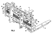
図1は一対のフォーク5を動かすためのフォーク作動アセンブリ1を示す。このフォーク作動アセンブリ1は、リフトブラケッド2と、サイドシフトフレーム20と、フォークポジショニング装置3とを備えている。
FIG. 1 shows a fork actuation assembly 1 for moving a pair of
図2は、間隔をおいた二つの垂直メンバ6に対し溶接のような適当な方法で固定されたフレーム支持メンバ4を備えたリフトブラケッド2を示す。各垂直メンバ6は、リフトブラケッド2がフォークリフトマスト(図示せず)に沿って垂直に移動するのを可能にする2個またはそれ以上のベアリング8を備えている。垂直メンバ6も下部リフトブラケッド・バー10に溶接されている。
FIG. 2 shows a
図3および図4を参照すると、フレーム支持メンバ4は、このフレーム支持メンバ4に沿って横方向に摺動するように構成されたサイドシフトフレーム20を支持している(下記に詳述する)。このサイドシフトフレーム20は、サイドメンバ26によって結合されて矩形形状を形成するのが好ましい、水平な上側クロスメンバ22および下側クロスメンバ24とを備えている。サイドシフトフレーム20は、いかなる適当な方法によって結合しても差し支えないが、溶接されているのが好ましい。上側クロスメンバ22は、フォーク5が、その柄部分に設けられて上側クロスメンバ22に固定された鉤状部を備えていることによってフォーク5を支持している。2個のコンタクトパッド25が上側クロスメンバ22に固定されている。
Referring to FIGS. 3 and 4, the
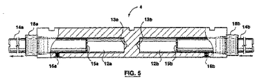
図3および図5を参照すると、サイドシフトフレーム20は、サイドシフト作動装置によってフレーム支持メンバ4に沿って移動せしめられる。サイドシフト作動装置は、それぞれコンタクトパッド25が終端となるピストン14a,14bを備えていることが好ましい。コンタクトパッド25は、一定の幅を有する標準的なリフトブラケッド2を、幅の異なるサイドシフトフレーム20に調和させるのを可能にする。図5に示されているように、ピストン14a,14bは、フレーム支持メンバ4内に画成された軸方向の空洞12a,12b内にそれぞれ収容されている。空洞12a,12bは、機械加工によってフレーム支持メンバ4に開けられるのが好ましく、機械加工された面取り穴13a,13bを各空洞の内端に備えているのが好ましい。空洞12a,12bは、作動液のポート16a,16bにそれぞれ連通しているのが好ましい。ピストン14a,14bと空洞12a,12bとの間のシールはパッキン押さえナット18a,18bによって提供される。ピストン14a,14bは、それらの内端の直径方向に沿って加工されたノッチ15a,15bをそれぞれ備えている。電動モータまたはチェーン駆動のようなその他の適当な他のシフト手段を採用してもよいことは、当業者であれば理解されるであろう。
3 and 5, the
図2および図7を参照すると、上側クロスメンバ22は、フレーム支持メンバ4の上向き接触面30に係合する下向き接触面28を備えて、サイドシフトフレーム20のフレーム支持メンバ4に沿った摺動を容易にしている。上記下向き接触面28が凹状断面形状を備え、かつ上記上向き接触面30が凸状の断面形状を備えて上記係合が達成されることが好ましい。これらの形状により、フレーム支持メンバ4上の上側クロスメンバ22の位置が確保される。しかしながら、上記とは反対の形状でも、または摺動係合が提供されるのに適した他の形状でもよいことは、当業者であれば理解されるであろう。図3に示されているように、凸状の上向き接触面30には磨耗防止パッド31が固定されて、フレーム支持メンバ4および上側クロスメンバ22の摩滅を防止している。上側クロスメンバ22はまた、ピストン14a,14bのような可動部材が、荷物すなわちフォーク5によって損傷を受けるのを防止するために、フレーム支持メンバ4に覆いかぶさる平坦部分32をも備えている。上側クロスメンバ22の平坦部分32は前面33を備えている。上側クロスメンバ22およびフレーム支持メンバ4の係合面28,30の形状のみならず平坦部分32の形状はすべて、サイドシフトフレーム20を追加することによって発生するロストロードを最少にするのに貢献している。
2 and 7, the
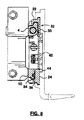
図8を参照すると、下部リフトブラケッドバー10は、下側クロスメンバ24内に画成された溝36に係合するレール部分34を備えている。ここにも磨耗防止パッド31が設けられて、下部リフトブラケッドバー10および下側クロスメンバ24を保護している。
Referring to FIG. 8, the lower
図4は第1および第2フォークシュー40a,40bを示す。各フォークシューは2個のリブ41を備えているのが好ましく、これらリブはフォークを位置決めするためにフォークの柄部分に係合しているが、フォークに係合するための他の適当な手段を用いてもよい。各フォークシューはリブ41間に接触面42を備え、この接触面にフォークの柄部分の後部が支持されている。
FIG. 4 shows the first and
ここで図7を参照すると、フォークシュー40a,40bは下側クロスメンバ24の上部に画成された摺動面44に沿って移動するのが好ましい。各フォークシュー40a,40bのフォーク接触面42は、上側クロスメンバ22の前面33によって画成された平面よりも前方には位置していない。サイドシフトフレーム20(フォークの後部がこれに支えられている)全体の前面と、フォークシュー40a,40bの接触面42とが上記前面33と同一平面上にあることがより好ましい。したがって、フォーク位置決めシュー40a,40bが追加されても、フォークリフトのロードモーメントを増大させない。
Referring now to FIG. 7, the fork shoes 40 a, 40 b preferably move along a sliding
図3および図4を参照すると、フォークポジショニング装置3は、下記のように、液圧アセンブリとチェーン駆動機構の組合せから構成されている。液圧シリンダ46の一端は、第2フォークシュー40bの近傍のサイドメンバ26に取り付けられている。液圧シリンダ46は、サイドメンバ26にボルト止めされているシリンダUリンク48にボルトによって取り付けられているのが好ましい。可動シリンダロッド50は、通常の態様で液圧シリンダ46内に収容されかつシールされている。シリンダロッド50の自由端は、上述の構成に類似した、シリンダUリンクとボルト止め構造のような、適当な方法で第1フォークシュー40aに取り付けられている。二つの作動液ポート52a,52bがシリンダの各端部に設けられている。
Referring to FIGS. 3 and 4, the fork positioning device 3 is composed of a combination of a hydraulic assembly and a chain drive mechanism as described below. One end of the
第1フォークシュー40aを移動させるのに他の適当な手段を備えていてもよいことは当業者であれば理解されるであろう。例えば、フォークポジショニング装置が電動モータとギア駆動機構であってもよい。
One skilled in the art will appreciate that other suitable means may be provided for moving the
ここで図3および図4を参照すると、フォークポジショニング装置3は、二つのフォークシューをサイドシフトフレーム20の中心から等距離に保つために、第1フォークシュー40aの移動時に第2フォークシュー40bも移動させるセンタリングアセンブリを備えている。このセンタリングアセンブリは上側チェーン60を備え、この上側チェーン60は、第1チェーンマウント62によって第1フォークシュー40aの後部に固定され、かつチェーンスプロケット64によってフォークシュー40bの近傍のサイドメンバ26に固定されているのが好ましい。上側チェーン60はまた、第2チェーンマウント68によってフォークシュー40bにも固定されている。下側チェーン66は、第2チェーンマウント68によって第2フォークシュー40bの後部に固定され、かつチェーンスプロケット69によってフォークシュー40a近傍の第1フォークシュー40aに固定されている。下側チェーン66は、第1チェーンマウント62によってフォークシュー40aに固定されている。チェーンマウント62、68はそれぞれ両端において接続されて一連のチェーンループを形成している。スプロケット64,69は、耐摩耗性を改善するために、焼入れされた鋼鉄で作成されているのが好ましい。フォークシュー40a,40bのセンタリングは、ケーブル駆動またはギア駆動のような他の適当な手段と組み合わされていてもよいことは、当業者であれば理解されるであろう。
Referring now to FIGS. 3 and 4, the fork positioning device 3 also includes the
フォーク作動アセンブリ1がフォークシュー40およびフォークポジショニング装置3を備えていなくてもよいことは、当業者であれば理解されるであろう。このことは、サイドシフティング機能のみを要求するか、あるいは部品を段階的に購入してフォークポジショニング機能のための追加コストは先送りすることを好む運用者にとってより多くの融通性を提供する利点がある。本発明のさらなる利点は、後日ユーザーがフォークポジショニング機能を付加することを望んだ場合に、フォークシュー40およびフォークポジショニング装置3を容易に後付けすることができることである。この利点により、特殊化されたサービス施設にアセンブリを戻す必要性が回避され、あるいは現存のアセンブリを、サイドシフティング機能およびフォークポジショニング機能の双方の能力を備えた新規のアセンブリに交換する必要性が回避される。
One skilled in the art will appreciate that the fork actuation assembly 1 may not include the
再び図3および図5を参照すると、フォーク作動アセンブリのサイドシフティング動作が記載されている。一対のフォークを一方側にサイドシフトするために、操縦者は作動液を作動液源(図示せず)からポート16aを通じて空洞12a内に圧送する。ピストン14aが液圧により空洞12aから押し出される。ピストン14aは、上側クロスメンバ22に固定されているコンタクトパッド25を押すことにより、サイドシフトフレーム20を同じ方向に強制的に移動させる。同時に、ピストン14bが空洞12b内に引っ込み、作動液はポート16bを通じて空洞12bから排出される。もし操縦者がサイドシフトフレーム20をその移動範囲の端まで移動させた場合には、孔13bに残存している作動液が、ピストン14bの端部の制限ノッチ15bを通じて逃れることによって、空洞12bの壁に当るピストン14bの衝撃が緩衝される。
Referring again to FIGS. 3 and 5, the side shifting operation of the fork actuation assembly is described. In order to side shift the pair of forks to one side, the operator pumps hydraulic fluid from a hydraulic fluid source (not shown) into the cavity 12a through the port 16a. The piston 14a is pushed out of the cavity 12a by hydraulic pressure. The piston 14a forcibly moves the
サイドシフトフレーム20を反対方向に移動させるために、操縦者は作動液を空洞12b内に圧送して、上述と同様の態様で、サイドシフトフレーム20を反対方向に移動させる。
In order to move the
図3および図4を参照して、フォーク作動アセンブリ1のフォークポジショニング動作を説明する。フォーク5間の間隔を狭めるために、操縦者は作動液をポート52bに圧送する。作動液はロッド50を液圧シリンダ46内に引っ込ませ、これにより、第1フォークシュー40aをサイドシフトフレーム20の反対側に向かって移動させる。フォークシュー40aが移動すると、上側チェーン60および下側チェーン66によって形成されたチェーンループを引っ張る。第2フォークシュー40bが下側チェーン66に固定されているので、フォークシュー40bは同時にサイドシフトフレーム20の反対側に向かって移動する。続いてフォークシュー40a,40bが互いに接近する方向に同一距離移動する。このことは、サイドシフトフレーム20上のフォークを連続的にセンンタリンングするという重要な機能を提供し、これによって荷物が偏る可能性が低減する。
The fork positioning operation of the fork actuation assembly 1 will be described with reference to FIGS. 3 and 4. In order to reduce the distance between the
フォーク5間の間隔を広げるためには、操縦者は作動液をポート52aに圧送して、ロッド50を液圧シリンダ46の外へ押し出させる。フォークシュー40a,40bは、上述と同様の態様で、互いに離れる方向に同一距離移動する。
In order to widen the space between the
本発明は、その精神または本質的な特徴から離れることなしに他の特定形態においても実施可能である。したがって、ここに開示された実施例はすべての点で説明のためのもの的であって、限定のためのものではないと判断され、本発明の範囲は、上述の記載によってではなく添付の請求の範囲によって規定され、かつ請求項の意味および等価の範囲内にあるすべての変更は本発明に含まれることを意図するものである。 The present invention may be embodied in other specific forms without departing from its spirit or essential characteristics. Accordingly, the embodiments disclosed herein are to be considered in all respects as illustrative and not restrictive, and the scope of the present invention is not limited by the foregoing description, but by the appended claims All modifications that are defined by the scope of the claims and that fall within the meaning and range of equivalency of the claims are intended to be embraced by the present invention.
1 フォーク作動アセンブリ
2 リフトブラケッド
3 フォークポジショニング装置
4 フレーム支持メンバ
5 フォーク
6 垂直メンバ
14a,14b ピストン
10 リフトブラケッドバー
20 サイドシフトフレーム
22 上側クロスメンバ
24 下側クロスメンバ
25 コンタクトパッド
DESCRIPTION OF SYMBOLS 1
Claims (21)
a)水平方向に間隔をおいた一対の垂直メンバと、該垂直メンバに対し横方向に固定されたフレーム支持メンバとを備えたリフトブラケッドであって、前記垂直メンバは前記マスト内部に移動可能に取り付けられるように構成されたものであるリフトブラケッド、
b)上側クロスメンバと、間隔をおいた下側クロスメンバと、前記上側クロスメンバと前記下側クロスメンバとを連結する一対のサイドメンバとを備えたサイドシフトフレームであって、前記上側クロスメンバが前記一対のフォークを前記鉤状部において支持するように構成され、該上側クロスメンバが前面を画成し、前記下側クロスメンバが摺動面を画成し、該摺動面は、前記フォークの前記柄部分が前記上側クロスメンバの前記前面よりもさらに前方には出ないような前記フォークの位置決めを可能にするように構成されたものであるサイドシフトフレーム、および
c)前記サイドシフトフレームの前記フレーム支持メンバに沿った移動を生じさせるためのサイドシフト作動装置であって、前記フレーム支持メンバの一部分内に配置されてなるサイドシフト作動装置、
を有することを特徴とするフォーク作動アセンブリ。 A fork actuation assembly for a forklift, comprising a mast and a pair of forks, each of the pair of forks comprising a hook-like portion provided on a handle portion thereof.
a) A lift bracket comprising a pair of vertical members spaced apart in the horizontal direction and a frame support member fixed laterally to the vertical members, the vertical members being movable within the mast. Lift bracket, which is configured to be attached to
b) A side shift frame comprising an upper cross member, a spaced lower cross member, and a pair of side members connecting the upper cross member and the lower cross member, the upper cross member Is configured to support the pair of forks at the bowl-shaped portion, the upper cross member defines a front surface, the lower cross member defines a sliding surface, and the sliding surface is A side shift frame configured to enable positioning of the fork so that the handle portion of the fork does not protrude further forward than the front surface of the upper cross member; and c) the side shift frame A side shift actuating device for causing movement along the frame support member, wherein the side shift actuator is disposed within a portion of the frame support member Side shift actuator,
A fork actuating assembly comprising:
b)前記第1フォークシューを前記第2フォークシューと相対的に移動させるように構成されたフォークポジショニング装置であって、前記第1および第2フォークシューに機能的に連結されてなるフォークポジショニング装置、
をさらに有することを特徴とする請求項1記載のフォーク作動アセンブリ。 a) a first fork shoe and a second fork shoe configured to slide along the sliding surface, each configured to engage with one of the pair of forks; First and second fork shoes that define a contact surface configured to support the handle portion, and the fork contact surface is disposed so as not to protrude further forward than the front surface of the upper cross member. And b) a fork positioning device configured to move the first fork shoe relative to the second fork shoe, the fork being functionally connected to the first and second fork shoes. Positioning device,
The fork actuation assembly of claim 1 further comprising:
a)前記サイドシフトフレームに連結された液圧シリンダであって、作動液供給源に連通する第1および第2シリンダポートを画成する液圧シリンダ、
b)前記液圧シリンダ内に収容されたロッドであって、前記液圧シリンダ内で往復移動するように構成され、第1フォークシューに固定された自由端を有し、作動液が前記第1シリンダポートに流入するのに伴って前記第1フォークシューを前記液圧シリンダから離れる方向に移動させるように構成され、かつ、作動液が前記第2シリンダポートに流入するのに伴って前記第1フォークシューを前記液圧シリンダに向かって移動させるように構成されたロッド、および
c)前記第1フォークシューの移動に伴って前記第2フォークシューを移動させるように構成されたセンタリングアセンブリであって、前記第1および第2フォークシューが前記サイドシフトフレームの中心から等距離に保たれるものであるセンタリングアセンブリ、
を有することを特徴とする請求項8記載のフォーク作動アセンブリ。 The fork positioning device is
a) a hydraulic cylinder coupled to the side shift frame, the hydraulic cylinder defining first and second cylinder ports communicating with a hydraulic fluid supply source;
b) a rod housed in the hydraulic cylinder, configured to reciprocate within the hydraulic cylinder, having a free end fixed to a first fork shoe, and the working fluid being the first The first fork shoe is configured to move in a direction away from the hydraulic cylinder as it flows into the cylinder port, and the first fluid as the hydraulic fluid flows into the second cylinder port. A rod configured to move the fork shoe toward the hydraulic cylinder; and c) a centering assembly configured to move the second fork shoe as the first fork shoe moves. A centering assembly in which the first and second fork shoes are kept equidistant from the center of the side shift frame;
9. A fork actuating assembly according to claim 8, comprising:
a)水平方向に間隔をおいた一対の垂直メンバと、該垂直メンバに対し横方向に固定されたフレーム支持メンバとを備えたリフトブラケッドであって、前記垂直メンバは前記マスト内部に移動可能に取り付けられ、前記フレーム支持メンバは前面および上向き接触面を画成するものであるリフトブラケッド、
b)サイドシフトフレームであって、前記一対のフォークを支持するように構成された上側クロスメンバを備え、該上側クロスメンバは、
イ)前記フレーム支持メンバの前記前面を覆う平面状前部と、
ロ)摺動運動のために前記フレーム支持メンバの前記上向き接触面に係合する下向き接触面と
を備えるものであるサイドシフトフレーム、および
c)前記サイドシフトフレームの前記フレーム支持メンバに沿った移動のためのサイドシフト作動装置であって、前記フレーム支持メンバの一部分内に配置されてなるサイドシフト作動装置、
を有することを特徴とするサイドシフティング・アセンブリ。 In a side shifting assembly for a forklift having a mast and a pair of forks,
a) A lift bracket comprising a pair of vertical members spaced apart in the horizontal direction and a frame support member fixed laterally to the vertical members, the vertical members being movable within the mast. A lift bracket, wherein the frame support member defines a front surface and an upward contact surface;
b) a side shift frame comprising an upper cross member configured to support the pair of forks, the upper cross member comprising:
A) a planar front portion covering the front surface of the frame support member;
B) a side shift frame having a downward contact surface that engages the upward contact surface of the frame support member for sliding movement; and c) movement of the side shift frame along the frame support member. A side shift actuating device for a side shift actuating device arranged within a portion of the frame support member,
A side shifting assembly comprising:
a)水平方向に間隔をおいた一対の垂直メンバと、該垂直メンバに対し横方向に固定されたフレーム支持メンバとを備えたリフトブラケッドであって、前記垂直メンバが前記マスト内部に移動可能に取り付けられたものであるリフトブラケッド、
b)上側クロスメンバを備えたサイドシフトフレームであって、前記上側クロスメンバが前記サイドシフトフレームに摺動可能に連結され、該一対の上側クロスメンバが前記フォークを前記鉤状部に沿って支持するように構成されたものであるサイドシフトフレーム、
c)前記サイドシフトフレームを前記フレーム支持メンバに沿って移動させるシフティング装置であって、前記フレーム支持メンバの一部分内に配置されたシフティング装置、
d)前記サイドシフトフレームに移動可能に取り付けられた第1フォークシューおよび第2フォークシューであって、それぞれが前記柄部分に係合するように構成されたフォーク接触面を構成し、該フォーク接触面は前記上側クロスメンバの前面よりもさらに前方には出ないように配置されている第1および第2フォークシュー、
e)前記第1フォークシューを前記第2フォークシューと相対的に移動させるように構成されたフォークポジショニング装置であって、前記第1および第2フォークシューは前記サイドシフトフレームの中心から等距離に保たれ、前記第1および第2フォークシューに機能的に連結されてなるフォークポジショニング装置、
を有することを特徴とするフォーク作動アセンブリ。 A fork actuation assembly for a forklift, comprising a mast and a pair of forks, each of the pair of forks comprising a hook-like portion provided on a handle portion thereof.
a) A lift bracket including a pair of vertical members spaced apart in the horizontal direction and a frame support member fixed laterally with respect to the vertical members, the vertical members being movable into the mast. Lift bracket, which is attached to
b) A side shift frame having an upper cross member, wherein the upper cross member is slidably connected to the side shift frame, and the pair of upper cross members support the fork along the hook-shaped portion. Side shift frame, which is configured to
c) a shifting device for moving the side shift frame along the frame support member, wherein the shifting device is disposed within a part of the frame support member;
d) a first fork shoe and a second fork shoe movably attached to the side shift frame, each of which constitutes a fork contact surface configured to engage with the handle portion, the fork contact First and second fork shoes arranged such that the surface does not protrude further forward than the front surface of the upper cross member;
e) A fork positioning device configured to move the first fork shoe relative to the second fork shoe, wherein the first and second fork shoes are equidistant from the center of the side shift frame. A fork positioning device that is held and operatively connected to the first and second fork shoes;
A fork actuating assembly comprising:
Applications Claiming Priority (2)
| Application Number | Priority Date | Filing Date | Title |
|---|---|---|---|
| US10/078,521 US20030156935A1 (en) | 2002-02-21 | 2002-02-21 | Fork movement assembly for lift trucks |
| PCT/CA2003/000211 WO2003070617A1 (en) | 2002-02-21 | 2003-02-14 | Fork movement assembly for lift trucks |
Publications (1)
| Publication Number | Publication Date |
|---|---|
| JP2005517618A true JP2005517618A (en) | 2005-06-16 |
Family
ID=27732842
Family Applications (1)
| Application Number | Title | Priority Date | Filing Date |
|---|---|---|---|
| JP2003569536A Pending JP2005517618A (en) | 2002-02-21 | 2003-02-14 | Fork actuation assembly for forklift |
Country Status (7)
| Country | Link |
|---|---|
| US (1) | US20030156935A1 (en) |
| EP (1) | EP1476389A1 (en) |
| JP (1) | JP2005517618A (en) |
| CN (1) | CN1639052A (en) |
| AU (1) | AU2003206517A1 (en) |
| CA (1) | CA2476353A1 (en) |
| WO (1) | WO2003070617A1 (en) |
Cited By (2)
| Publication number | Priority date | Publication date | Assignee | Title |
|---|---|---|---|---|
| KR20200042174A (en) * | 2018-10-15 | 2020-04-23 | (주)금우기공 | A Multifunctional Fork Shifting Assembly for Forklift |
| JP2023518636A (en) * | 2020-01-08 | 2023-05-08 | カスケード コーポレイション | Attachments for industrial material handling equipment |
Families Citing this family (24)
| Publication number | Priority date | Publication date | Assignee | Title |
|---|---|---|---|---|
| US8087868B2 (en) | 2004-01-13 | 2012-01-03 | Moffett Research And Development Limited | Forklift truck for mounting on the rear of a carrying vehicle with a fork side shifting attachment |
| GB2414008A (en) * | 2004-05-11 | 2005-11-16 | Blaker Design Ltd | Lifting fork control mechanism |
| FI20041280A7 (en) * | 2004-10-01 | 2006-04-02 | Rocla Oyj | Method and apparatus for laterally moving a forklift fork carriage |
| CN103274337A (en) * | 2013-05-08 | 2013-09-04 | 常熟通润汽车修理设备有限公司 | Tire conveying lifting device |
| DE102013209906A1 (en) * | 2013-05-28 | 2014-12-04 | Rogama Bv | Carriage tilt |
| DE112014003034T5 (en) | 2013-06-28 | 2016-03-24 | Rightline Equipment, Inc | Sideshift with embedded actuator |
| CN103434987A (en) * | 2013-08-28 | 2013-12-11 | 牛力机械制造有限公司 | Forklift pallet fork distance adjusting assembly |
| DE102014209390A1 (en) * | 2014-05-19 | 2015-11-19 | Rogama Bv | Load handling carrier |
| CN106255660B (en) | 2014-06-26 | 2019-08-27 | 克朗设备公司 | Bracket assembly for a material handling vehicle and method of making the same |
| US9932213B2 (en) | 2014-09-15 | 2018-04-03 | Crown Equipment Corporation | Lift truck with optical load sensing structure |
| FI3034453T4 (en) * | 2014-12-18 | 2024-06-06 | Manitou Italia Srl | An equipment with side-shifter |
| CN104909305A (en) * | 2015-06-16 | 2015-09-16 | 安徽合力股份有限公司 | Side-shifting brick fork for forklift |
| CN105731311B (en) * | 2016-05-05 | 2018-08-24 | 朱红蔚 | Rectangular co-ordinate rail carry loads and unloads robot |
| CA3294745A1 (en) | 2017-06-08 | 2026-03-02 | Cascade Corporation | Fork-carriage apparatus for a lift truck and valve assembly therefor |
| CN107500193A (en) * | 2017-10-17 | 2017-12-22 | 余伟宏 | A kind of fork of forklift truck being conveniently adjusted |
| CN108675224A (en) * | 2018-05-23 | 2018-10-19 | 中国人民解放军济南军区72465部队 | Heavy-duty vehicle executing mechanism repairs tooling |
| CN109179268B (en) * | 2018-10-18 | 2020-05-05 | 合肥搬易通科技发展有限公司 | Double-distance-adjusting fork mechanism for carrying silk-axis goods |
| CN109292692B (en) * | 2018-11-23 | 2024-08-30 | 安庆联动属具股份有限公司 | Fork truck roll adjustment fork |
| DE102019006140A1 (en) * | 2019-08-30 | 2021-03-04 | Kaup GmbH & Co. KG Gesellschaft für Maschinenbau | Device for transporting a cargo and method |
| IT201900018926A1 (en) * | 2019-10-15 | 2021-04-15 | Elett 80 S P A | APPARATUS FOR OPERATING THE FORK SUPPORTS OF A FORKLIFT |
| US11365104B2 (en) | 2020-01-08 | 2022-06-21 | Cascade Corporation | Attachments for industrial material handling equipment |
| US11906347B2 (en) | 2021-08-20 | 2024-02-20 | Buckeye Scale Llc | Adjustable width lift and weigh apparatus for lifting machines |
| US20230058101A1 (en) * | 2021-08-23 | 2023-02-23 | Brandon Michael West | Powered Industrial Truck (PIT) with Rear-Loading/Lifting Mechanism |
| WO2025040942A1 (en) * | 2023-08-21 | 2025-02-27 | Gonzalez Sanchez Jose | Device for rotating the forks of a forklift 180 degrees |
Family Cites Families (15)
| Publication number | Priority date | Publication date | Assignee | Title |
|---|---|---|---|---|
| US3241698A (en) * | 1964-02-27 | 1966-03-22 | Allis Chalmers Mfg Co | Side shifting carriage for lift truck |
| GB2043029B (en) * | 1978-08-17 | 1982-10-20 | Toyoda Automatic Loom Works | Device for loading and unloading lift truck |
| US4392772A (en) * | 1980-04-07 | 1983-07-12 | Towmotor Corporation | Load lifting carriage having side shift adjustable forks |
| DE8518185U1 (en) * | 1985-06-22 | 1985-08-08 | Kaup GmbH & Co KG Gesellschaft für Maschinenbau, 8750 Aschaffenburg | Fork adjustment device |
| US5096363A (en) * | 1990-09-25 | 1992-03-17 | Cascade Corporation | Multiple-pair fork positioner |
| US5190436A (en) * | 1991-06-06 | 1993-03-02 | Caterpillar Industrial Inc. | Carriage assembly having side shiftable and adjustable forks |
| US5807060A (en) * | 1992-06-11 | 1998-09-15 | Rightline Equipment, Inc. | Forklift truck side shifter |
| US5707201A (en) * | 1992-06-11 | 1998-01-13 | Rightline Equipment, Inc. | Forklift truck side shifter |
| US5368435A (en) * | 1993-01-28 | 1994-11-29 | Brudi, Inc. | Side shifter attachment and retainer for lift truck attachments |
| DE19602055C1 (en) * | 1996-01-20 | 1997-04-17 | Kaup Gmbh & Co Kg | Side slide device for forklift truck |
| DE19602553C2 (en) * | 1996-01-25 | 1999-10-14 | Kaup Gmbh & Co Kg | Pressure medium drive with a cylinder and a plunger |
| IT236473Y1 (en) * | 1997-02-13 | 2000-08-17 | Bolzoni Spa | DEVICE FOR MOVING THE FORKS ON A FORKLIFT |
| DE19903157C2 (en) * | 1999-01-27 | 2002-11-21 | Kaup Gmbh & Co Kg | Attachment for industrial trucks with a mast, especially for forklifts |
| US6390763B1 (en) * | 2000-05-30 | 2002-05-21 | Cascade Corporation | Lift truck carriage with improved sideshifter |
| DE20020292U1 (en) * | 2000-11-18 | 2001-04-26 | Jungheinrich Ag, 22047 Hamburg | Load sled for industrial trucks |
-
2002
- 2002-02-21 US US10/078,521 patent/US20030156935A1/en not_active Abandoned
-
2003
- 2003-02-14 AU AU2003206517A patent/AU2003206517A1/en not_active Abandoned
- 2003-02-14 CA CA002476353A patent/CA2476353A1/en not_active Abandoned
- 2003-02-14 CN CNA038044269A patent/CN1639052A/en active Pending
- 2003-02-14 WO PCT/CA2003/000211 patent/WO2003070617A1/en not_active Ceased
- 2003-02-14 EP EP03704118A patent/EP1476389A1/en not_active Withdrawn
- 2003-02-14 JP JP2003569536A patent/JP2005517618A/en active Pending
Cited By (4)
| Publication number | Priority date | Publication date | Assignee | Title |
|---|---|---|---|---|
| KR20200042174A (en) * | 2018-10-15 | 2020-04-23 | (주)금우기공 | A Multifunctional Fork Shifting Assembly for Forklift |
| KR102139960B1 (en) * | 2018-10-15 | 2020-08-11 | (주)금우기공 | A Multifunctional Fork Shifting Assembly for Forklift |
| JP2023518636A (en) * | 2020-01-08 | 2023-05-08 | カスケード コーポレイション | Attachments for industrial material handling equipment |
| JP7603070B2 (en) | 2020-01-08 | 2024-12-19 | カスケード コーポレイション | Attachments for industrial material handling equipment |
Also Published As
| Publication number | Publication date |
|---|---|
| EP1476389A1 (en) | 2004-11-17 |
| AU2003206517A1 (en) | 2003-09-09 |
| WO2003070617A1 (en) | 2003-08-28 |
| CN1639052A (en) | 2005-07-13 |
| CA2476353A1 (en) | 2003-08-28 |
| US20030156935A1 (en) | 2003-08-21 |
Similar Documents
| Publication | Publication Date | Title |
|---|---|---|
| JP2005517618A (en) | Fork actuation assembly for forklift | |
| US20100065377A1 (en) | Monomast for a materials handling vehicle | |
| CA2875383A1 (en) | Device and system for lifting a motor vehicle | |
| EP1481942B1 (en) | A truck mounted forklift with double-acting freelift mast | |
| US20090279994A1 (en) | Fork assembly lift mechanism | |
| US4585093A (en) | Upright for lift truck | |
| ATE272570T1 (en) | ATTACHMENT FOR INDUSTRIAL TRUCKS WITH A LIFTING MAST, ESPECIALLY FOR FORKLIFT TRUCKS | |
| US5480275A (en) | Fork lift truck | |
| WO2006037841A1 (en) | Method and assembly for shifting the fork cradle of a forklift truck laterally and for tilting it longitudinally | |
| JP5368029B2 (en) | forklift | |
| US3485323A (en) | Lift truck mast and ram assembly | |
| US3062325A (en) | Lift truck load chain sheave construction | |
| EP0579669B1 (en) | Hydraulic ram assemblies | |
| KR100283854B1 (en) | Hydraulic controller of wheel dolly | |
| EP3178775B1 (en) | Mast segment for a lift-truck and a lift-truck comprising a mast segment | |
| JP5133733B2 (en) | Work vehicle | |
| JP2003212486A (en) | Method for fixing pallet of load handling vehicle | |
| JP3348638B2 (en) | Mast device for forklift truck | |
| KR102949301B1 (en) | Forklift crane boom mounting structure | |
| CN216613924U (en) | Side shifting fork frame for small-tonnage forklift | |
| JP4259914B2 (en) | Crawler belt adjustment device | |
| JP4583184B2 (en) | Forklift equipment | |
| KR20160073246A (en) | Power Pack Operating Apparatus of Forklift | |
| KR20240012097A (en) | Pallet mover for autonomous mobile robot | |
| JPS6337100A (en) | Side shifting structure of lift gear |
Legal Events
| Date | Code | Title | Description |
|---|---|---|---|
| A621 | Written request for application examination |
Free format text: JAPANESE INTERMEDIATE CODE: A621 Effective date: 20060208 |
|
| A131 | Notification of reasons for refusal |
Free format text: JAPANESE INTERMEDIATE CODE: A131 Effective date: 20080826 |
|
| A02 | Decision of refusal |
Free format text: JAPANESE INTERMEDIATE CODE: A02 Effective date: 20090210 |