JP2005513865A - Quality of service setting by time reservation system - Google Patents
Quality of service setting by time reservation system Download PDFInfo
- Publication number
- JP2005513865A JP2005513865A JP2003553771A JP2003553771A JP2005513865A JP 2005513865 A JP2005513865 A JP 2005513865A JP 2003553771 A JP2003553771 A JP 2003553771A JP 2003553771 A JP2003553771 A JP 2003553771A JP 2005513865 A JP2005513865 A JP 2005513865A
- Authority
- JP
- Japan
- Prior art keywords
- video conference
- client
- network
- session
- server
- Prior art date
- Legal status (The legal status is an assumption and is not a legal conclusion. Google has not performed a legal analysis and makes no representation as to the accuracy of the status listed.)
- Pending
Links
Images


Classifications
-
- H—ELECTRICITY
- H04—ELECTRIC COMMUNICATION TECHNIQUE
- H04L—TRANSMISSION OF DIGITAL INFORMATION, e.g. TELEGRAPHIC COMMUNICATION
- H04L65/00—Network arrangements, protocols or services for supporting real-time applications in data packet communication
- H04L65/1066—Session management
- H04L65/1101—Session protocols
- H04L65/1104—Session initiation protocol [SIP]
-
- G—PHYSICS
- G06—COMPUTING; CALCULATING OR COUNTING
- G06F—ELECTRIC DIGITAL DATA PROCESSING
- G06F15/00—Digital computers in general; Data processing equipment in general
- G06F15/16—Combinations of two or more digital computers each having at least an arithmetic unit, a program unit and a register, e.g. for a simultaneous processing of several programs
-
- H—ELECTRICITY
- H04—ELECTRIC COMMUNICATION TECHNIQUE
- H04L—TRANSMISSION OF DIGITAL INFORMATION, e.g. TELEGRAPHIC COMMUNICATION
- H04L12/00—Data switching networks
- H04L12/02—Details
- H04L12/16—Arrangements for providing special services to substations
- H04L12/18—Arrangements for providing special services to substations for broadcast or conference, e.g. multicast
- H04L12/1813—Arrangements for providing special services to substations for broadcast or conference, e.g. multicast for computer conferences, e.g. chat rooms
- H04L12/1827—Network arrangements for conference optimisation or adaptation
-
- H—ELECTRICITY
- H04—ELECTRIC COMMUNICATION TECHNIQUE
- H04L—TRANSMISSION OF DIGITAL INFORMATION, e.g. TELEGRAPHIC COMMUNICATION
- H04L12/00—Data switching networks
- H04L12/02—Details
- H04L12/16—Arrangements for providing special services to substations
- H04L12/18—Arrangements for providing special services to substations for broadcast or conference, e.g. multicast
- H04L12/185—Arrangements for providing special services to substations for broadcast or conference, e.g. multicast with management of multicast group membership
-
- H—ELECTRICITY
- H04—ELECTRIC COMMUNICATION TECHNIQUE
- H04L—TRANSMISSION OF DIGITAL INFORMATION, e.g. TELEGRAPHIC COMMUNICATION
- H04L41/00—Arrangements for maintenance, administration or management of data switching networks, e.g. of packet switching networks
- H04L41/08—Configuration management of networks or network elements
- H04L41/0893—Assignment of logical groups to network elements
-
- H—ELECTRICITY
- H04—ELECTRIC COMMUNICATION TECHNIQUE
- H04L—TRANSMISSION OF DIGITAL INFORMATION, e.g. TELEGRAPHIC COMMUNICATION
- H04L45/00—Routing or path finding of packets in data switching networks
-
- H—ELECTRICITY
- H04—ELECTRIC COMMUNICATION TECHNIQUE
- H04L—TRANSMISSION OF DIGITAL INFORMATION, e.g. TELEGRAPHIC COMMUNICATION
- H04L47/00—Traffic control in data switching networks
- H04L47/10—Flow control; Congestion control
-
- H—ELECTRICITY
- H04—ELECTRIC COMMUNICATION TECHNIQUE
- H04L—TRANSMISSION OF DIGITAL INFORMATION, e.g. TELEGRAPHIC COMMUNICATION
- H04L47/00—Traffic control in data switching networks
- H04L47/70—Admission control; Resource allocation
-
- H—ELECTRICITY
- H04—ELECTRIC COMMUNICATION TECHNIQUE
- H04L—TRANSMISSION OF DIGITAL INFORMATION, e.g. TELEGRAPHIC COMMUNICATION
- H04L47/00—Traffic control in data switching networks
- H04L47/70—Admission control; Resource allocation
- H04L47/80—Actions related to the user profile or the type of traffic
- H04L47/805—QOS or priority aware
-
- H—ELECTRICITY
- H04—ELECTRIC COMMUNICATION TECHNIQUE
- H04L—TRANSMISSION OF DIGITAL INFORMATION, e.g. TELEGRAPHIC COMMUNICATION
- H04L61/00—Network arrangements, protocols or services for addressing or naming
- H04L61/50—Address allocation
- H04L61/5069—Address allocation for group communication, multicast communication or broadcast communication
-
- H—ELECTRICITY
- H04—ELECTRIC COMMUNICATION TECHNIQUE
- H04L—TRANSMISSION OF DIGITAL INFORMATION, e.g. TELEGRAPHIC COMMUNICATION
- H04L65/00—Network arrangements, protocols or services for supporting real-time applications in data packet communication
- H04L65/1066—Session management
- H04L65/1083—In-session procedures
- H04L65/1093—In-session procedures by adding participants; by removing participants
-
- H—ELECTRICITY
- H04—ELECTRIC COMMUNICATION TECHNIQUE
- H04L—TRANSMISSION OF DIGITAL INFORMATION, e.g. TELEGRAPHIC COMMUNICATION
- H04L65/00—Network arrangements, protocols or services for supporting real-time applications in data packet communication
- H04L65/1066—Session management
- H04L65/1101—Session protocols
-
- H—ELECTRICITY
- H04—ELECTRIC COMMUNICATION TECHNIQUE
- H04L—TRANSMISSION OF DIGITAL INFORMATION, e.g. TELEGRAPHIC COMMUNICATION
- H04L65/00—Network arrangements, protocols or services for supporting real-time applications in data packet communication
- H04L65/40—Support for services or applications
- H04L65/403—Arrangements for multi-party communication, e.g. for conferences
- H04L65/4038—Arrangements for multi-party communication, e.g. for conferences with floor control
-
- H—ELECTRICITY
- H04—ELECTRIC COMMUNICATION TECHNIQUE
- H04L—TRANSMISSION OF DIGITAL INFORMATION, e.g. TELEGRAPHIC COMMUNICATION
- H04L65/00—Network arrangements, protocols or services for supporting real-time applications in data packet communication
- H04L65/60—Network streaming of media packets
- H04L65/75—Media network packet handling
- H04L65/752—Media network packet handling adapting media to network capabilities
-
- H—ELECTRICITY
- H04—ELECTRIC COMMUNICATION TECHNIQUE
- H04L—TRANSMISSION OF DIGITAL INFORMATION, e.g. TELEGRAPHIC COMMUNICATION
- H04L65/00—Network arrangements, protocols or services for supporting real-time applications in data packet communication
- H04L65/80—Responding to QoS
-
- H—ELECTRICITY
- H04—ELECTRIC COMMUNICATION TECHNIQUE
- H04M—TELEPHONIC COMMUNICATION
- H04M3/00—Automatic or semi-automatic exchanges
- H04M3/42—Systems providing special services or facilities to subscribers
- H04M3/56—Arrangements for connecting several subscribers to a common circuit, i.e. affording conference facilities
- H04M3/567—Multimedia conference systems
-
- H—ELECTRICITY
- H04—ELECTRIC COMMUNICATION TECHNIQUE
- H04M—TELEPHONIC COMMUNICATION
- H04M7/00—Arrangements for interconnection between switching centres
- H04M7/006—Networks other than PSTN/ISDN providing telephone service, e.g. Voice over Internet Protocol (VoIP), including next generation networks with a packet-switched transport layer
-
- H—ELECTRICITY
- H04—ELECTRIC COMMUNICATION TECHNIQUE
- H04N—PICTORIAL COMMUNICATION, e.g. TELEVISION
- H04N7/00—Television systems
- H04N7/14—Systems for two-way working
-
- H—ELECTRICITY
- H04—ELECTRIC COMMUNICATION TECHNIQUE
- H04N—PICTORIAL COMMUNICATION, e.g. TELEVISION
- H04N7/00—Television systems
- H04N7/14—Systems for two-way working
- H04N7/15—Conference systems
Abstract
ネットワークを通じて情報を送るルーティング・エレメントを有するネットワークにおいて、クライアント間でのテレビ会議セッションに対するサービス品質(QoS)契約を設定することができることを設ける方法を備える。テレビ会議セッションについての時間帯に対する予約が受信される。ネットワークを横断する他のトラフィックからのテレビ会議セッションに相当するリアル・タイム・トラフィックをフィルタする構成情報は時間帯が予約された後にルーティング・エレメントの少なくとも1つに対して送信される。 In a network having a routing element that sends information through the network, a method is provided for providing that a quality of service (QoS) contract can be established for a video conference session between clients. A reservation for a time slot for a video conference session is received. Configuration information that filters real time traffic corresponding to video conferencing sessions from other traffic across the network is transmitted to at least one of the routing elements after a time slot has been reserved.
Description
本発明は、一般に、テレビ会議、特に、テレビ会議セッションに対するサービス品質(QoS)契約及びトラフィック分類フィルタを設定する方法、に関するものである。該方法はQoS契約及びトラフィック分類フィルタを設定するのに時間予約を用いる。トラフィック分類フィルタはリアル・タイム・トラフィック(テレビ会議トラフィック)の非リアル・タイム・トラフィックとの差異を設ける。 The present invention relates generally to video conferencing, and in particular to a method for setting quality of service (QoS) contracts and traffic classification filters for video conference sessions. The method uses time reservations to set up QoS contracts and traffic classification filters. The traffic classification filter provides a difference between real-time traffic (video conference traffic) and non-real-time traffic.
一般に、テレビ会議は専用サービス総合ディジタル網(ISDN)及び/又はT1/T3回線上で実施される。これらの回線は2つの地理的に離れた場所の間の専用経路を設ける。このような解決策の欠点は専用回線が極めて高価で十分使われないことがあり得ることがある。テレビ会議が行われていないので専用回線が使われない場合には多くの帯域がむだになる。地理的に離れた場所を有する多くの企業は一般に、それらの間でのデータ・ネットワークを設ける専用回線(例えば、T1回線)を有する。専用回線によって各場所のローカル・エリア・ネットワーク(LAN)がお互いに接続されてワイド・エリア・ネットワーク(WAN)をもたらす。これらの回線の主たる効用は2つの場所間のデータ接続性である。 In general, video conferencing is conducted over a dedicated services integrated digital network (ISDN) and / or T1 / T3 lines. These lines provide a dedicated path between two geographically separated locations. The disadvantage of such a solution is that the dedicated line may be very expensive and not fully used. Since there is no video conference, a lot of bandwidth is wasted if a dedicated line is not used. Many businesses with geographically distant locations typically have dedicated lines (eg, T1 lines) that provide a data network between them. A local area network (LAN) at each location is connected to each other by a dedicated line to provide a wide area network (WAN). The main utility of these lines is data connectivity between the two locations.
各場所のLANは局所的にイーサネット(登録商標)・スイッチによって接続される。LANは多くの帯域のあるインフラストラクチャを設ける。LAN上の典型的な接続性帯域は100Mbps(全2重)である。これは一般に、エンド・ノードとそれらをWANに接続するルータとの間で利用可能な帯域が過剰になることを意味する。WAN上ではほとんど常に帯域の制約があるが、LAN上では全くないため、WANインタフェース上でトラフィックの種類(例えば、テレビ会議トラフィックのような、リアル・タイム・トラフィック、対 非リアル・タイム・トラフィック)による差異を設けることが特に重要である。非リアル・タイム・トラフィックに対するリアル・タイム・トラフィックの優先度の付与が行われず、WANリンク上で転送される情報量が利用可能帯域よりも大きい場合、輻輳が発生し、パケットの非選択的破棄を結果としてもたらす。LANは通常、輻輳が発生しないことを保証するよう利用可能な帯域の余分な量を当てにする。 The LANs at each location are locally connected by an Ethernet (registered trademark) switch. A LAN provides an infrastructure with a lot of bandwidth. A typical connectivity band on a LAN is 100 Mbps (full duplex). This generally means that there is an excess of bandwidth available between the end nodes and the routers connecting them to the WAN. Because there is almost always bandwidth limitations on the WAN but not on the LAN at all, the type of traffic on the WAN interface (for example, real-time traffic versus non-real-time traffic, such as video conference traffic) It is particularly important to make a difference due to If real-time traffic is not prioritized for non-real-time traffic and the amount of information transferred over the WAN link is greater than the available bandwidth, congestion occurs and non-selective discard of packets As a result. LANs typically rely on an extra amount of available bandwidth to ensure that no congestion occurs.
したがって、例えば、パケットの非選択的破棄、のような望ましくない影響を避けるよう、テレビ会議セッションに対して保証された帯域を設ける方法を有することが望ましく、かつ、特に効果的である。 Therefore, it is desirable and particularly effective to have a method of providing guaranteed bandwidth for a video conference session so as to avoid undesirable effects such as, for example, non-selective discarding of packets.
上記の課題、更には、先行技術の関連する課題、はテレビ会議セッションに関するサービス品質(QoS)契約及びトラフィック分類フィルタを設定する方法を用いた本発明によって解決されるものである。該方法はQoS契約及びトラフィック分類フィルタを設定するのに時間予約を使用する。トラフィック分類フィルタはリアル・タイム・トラフィック(テレビ会議トラフィック)と非リアル・タイム・トラフィックとの差異を設ける。 The above problems, as well as the related problems of the prior art, are solved by the present invention using a method of setting quality of service (QoS) contracts and traffic classification filters for video conference sessions. The method uses time reservations to set up QoS contracts and traffic classification filters. The traffic classification filter provides a difference between real time traffic (video conference traffic) and non-real time traffic.
本発明の特徴においては、ネットワークを通じて情報を送るルーティング・エレメントを有するネットワークにおいて、クライアント間でのテレビ会議セッションに関するサービス品質(QoS)契約を設定することができることを設ける方法を備える。テレビ会議セッションに対する時間帯について予約が受信される。ネットワークを横断する他のトラフィックからのテレビ会議セッションに相当するリアル・タイム・トラフィックをフィルタする構成情報が、時間帯が予約された後に該ルーティング・エレメントの少なくとも1つに送信される。 In a feature of the invention, there is provided a method for providing that a network having routing elements that send information through the network can set a quality of service (QoS) contract for a video conference session between clients. A reservation is received for a time slot for a video conference session. Configuration information that filters real-time traffic corresponding to video conference sessions from other traffic across the network is transmitted to at least one of the routing elements after the time zone has been reserved.
本発明の別の特徴によって、ネットワークを通じて情報を送るルーティング・エレメントを有するネットワークにおいて、クライアント間でのテレビ会議セッションに関するサービス品質(QoS)を設定することができることを設けるシステムを設ける。該システムはテレビ会議セッションに対する時間帯についての予約を受信する手段を含む。該システムは更に、ネットワークを横断する他のトラフィックからのテレビ会議セッションに相当するリアル・タイム・トラフィックをフィルタするよう、時間帯が予約された後にルーティング・エレメントの少なくとも1つに対して構成情報を送信する手段を含む。 In accordance with another aspect of the present invention, there is provided a system that provides for setting quality of service (QoS) for video conference sessions between clients in a network having routing elements that route information through the network. The system includes means for receiving a reservation for a time zone for a video conference session. The system further provides configuration information to at least one of the routing elements after a time slot has been reserved to filter real time traffic corresponding to video conference sessions from other traffic across the network. Means for transmitting.
本発明の更に別の特徴によって、ネットワークを通じて情報を送るルーティング・エレメントを有するネットワークにおいて、クライアント間でのテレビ会議セッションに対するサービス品質(QoS)契約を設定することができることを設ける方法を設ける。テレビ会議セッションに対する予約を送信することができることを設ける。該予約はテレビ会議セッションに対する時間帯を特定するので、クライアントは特定時間帯内でサービスの保証されたレベルを有するテレビ会議セッションに参加し得る。 According to yet another aspect of the present invention, there is provided a method for providing that a network having routing elements that route information through the network can establish a quality of service (QoS) contract for a video conference session between clients. Provide that reservations for video conference sessions can be sent. Since the reservation specifies a time zone for the video conference session, the client can participate in the video conference session having a guaranteed level of service within the specific time zone.
本発明のこれら及び他の特徴、特性、及び効果は好適実施例の以下の詳細説明、更には、添付図面、からわかるものである。 These and other features, characteristics and advantages of the present invention will become apparent from the following detailed description of the preferred embodiment, as well as the accompanying drawings.
本発明はテレビ会議セッションに関するサービス品質(QoS)契約及びトラフィック分類フィルタを設定する方法に関する。該方法はQoS契約及びトラフィック分類フィルタを設定するのに時間予約を使用する。トラフィック分類フィルタはリアル・タイム・トラフィック(テレビ会議トラフィック)の非リアル・タイム・トラフィックからの差異を設ける。 The present invention relates to a method for setting a quality of service (QoS) contract and a traffic classification filter for a video conference session. The method uses time reservations to set up QoS contracts and traffic classification filters. The traffic classification filter provides a difference between real-time traffic (videoconferencing traffic) and non-real-time traffic.
本発明はハードウェア、ソフトウェア、ファームウェア、特定用途向プロセッサ、又はその組み合わせの種々の形態において実施し得ることがわかる。本発明はハードウェア及びソフトウェアの組み合わせとして実施されるのが好適である。更に、ソフトウェアはプログラム記憶装置上で明白に実施されたアプリケーション・プログラムとして実施されることが好適である。アプリケーション・プログラムは如何なる適切なアーキテクチャを有するマシンに対してもアップロードし得、如何なる適切なアーキテクチャを有するマシンによっても実行し得る。マシンは1つ以上の中央処理装置(CPU)、ランダム・アクセス・メモリ(RAM)、及び入出力(I/O)インタフェースのようなハードウェアを有するコンピュータ・プラットフォーム上で実施される。コンピュータ・プラットフォームは更にオペレーティング・システム及びマイクロインストラクション・コードを含む。ここに記載する種々の処理及び機能は、オペレーティング・システムによって実行される、マイクロインストラクション・コードの一部又はアプリケーション・プログラムの一部(又はその組み合わせ)の何れかであり得る。更に、別のデータ記憶装置及び印刷装置のような種々の他の周辺装置をコンピュータ・プラットフォームに接続し得る。 It will be appreciated that the present invention may be implemented in various forms of hardware, software, firmware, application specific processors, or combinations thereof. The present invention is preferably implemented as a combination of hardware and software. Further, the software is preferably implemented as an application program that is explicitly implemented on the program storage device. Application programs can be uploaded to a machine with any suitable architecture and executed by a machine with any suitable architecture. The machine is implemented on a computer platform having hardware such as one or more central processing units (CPUs), random access memory (RAM), and input / output (I / O) interfaces. The computer platform further includes an operating system and microinstruction code. The various processes and functions described herein can be either part of the microinstruction code or part of the application program (or a combination thereof) executed by the operating system. In addition, various other peripheral devices may be connected to the computer platform such as another data storage device and a printing device.
更に、添付図面に表す構成システム部分及び方法工程の一部はソフトウェアによって実施されるのが好適であるので、システム構成部分(又は処理工程)間の実際の接続は本発明がプログラム化される方法によって変わってくることがあることがわかる。ここに表す教示を前提とすると、当業者は本発明のこれら及び類似した実施例及び構成を企図することができる。 Further, since some of the constituent system parts and method steps shown in the attached drawings are preferably implemented by software, the actual connection between the system constituent parts (or processing steps) is the way in which the invention is programmed. It can be seen that it may change depending on the situation. Given the teachings presented herein, one of ordinary skill in the related art will be able to contemplate these and similar embodiments and configurations of the present invention.
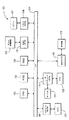
図1Aは本発明の例示的実施例による、本発明を形成し得るコンピュータ・システム100を示す構成図である。コンピュータ処理システム100はシステム・バス104経由で他の構成部分に動作するよう結合された少なくとも1つのプロセッサ(CPU)102を含む。読み取り専用メモリ(ROM)106、ランダム・アクセス・メモリ(RAM)108、表示アダプタ110、入出力アダプタ112、ユーザ・インタフェース・アダプタ114、サウンド・アダプタ199、及びネットワーク・アダプタ198がシステム・バス104に動作するよう結合される。
FIG. 1A is a block diagram illustrating a
表示装置116は表示アダプタ110によってシステム・バス104に動作するよう結合される。ディスク記憶装置(例えば、磁気又は光ディスク記憶装置)118は入出力アダプタ112によってシステム・バス104に動作するよう結合される。
マウス120及びキーボード122はユーザ・インタフェース・アダプタ114によってシステム・バス104に動作するよう結合される。マウス120及びキーボード122は情報をシステム100に入力して該システムから出力するのに用いられる。
Mouse 120 and
少なくとも1つのスピーカ(以降「スピーカ」)197はサウンド・アダプタ199によってシステム・バス104に動作するよう結合される。
At least one speaker (hereinafter “speaker”) 197 is operably coupled to the
(ディジタル及び/又はアナログ)モデム196はネットワーク・アダプタ198によってシステム・バス104に動作するよう結合される。
A (digital and / or analog)
次に、本発明の例示的実施例による、ポリシー・ベースのネットワーク管理(PBNM)を説明する。PBNMはネットワークを管理するようポリシーを規定して配信することができることを設ける技術である(本発明を形成し得る例示的ネットワークを図2によって以下に説明する。)。これらのポリシーによって帯域及びセキュリティのようなクリティカルなネットワーク・リソースの制御を連携させることを可能にする。PBNMはネットワーク上で差異のある待遇を必要とする、IPベースのテレビ会議のような、アプリケーションを動作可能にする。PBMNは異なる種類のアプリケーションが単一のネットワーク上で共存してこれらのアプリケーション各々に対して必要なリソースを設けることを可能にする基礎を設ける。 Next, policy-based network management (PBNM) according to an exemplary embodiment of the present invention will be described. PBNM is a technology that provides that policies can be defined and distributed to manage a network (an exemplary network that can form the present invention is described below with reference to FIG. 2). These policies allow coordinated control of critical network resources such as bandwidth and security. PBNM enables applications such as IP-based video conferencing that require different treatment on the network. PBMN provides the basis that allows different types of applications to coexist on a single network and provide the necessary resources for each of these applications.
更に詳細には、PBNMはネットワーク・リソースを消費するアプリケーション及びユーザに対するポリシーを規定する。例えば、ビジネス・クリティカルなアプリケーションはネットワーク上の最高の優先度及び帯域の一部を得ることができ、ビデオ会議及びボイス・オーバIPは次に高い優先度を得ることができ、更に、最後に、厳密な帯域又はタイム・クリティカルな制約を有しないウェブ・トラフィック及びファイル転送はネットワーク上の残りのリソースを得ることができる。このユーザ及びアプリケーションの差異はPBNMによって実現し得る。 More specifically, PBNM defines policies for applications and users that consume network resources. For example, business critical applications can get some of the highest priority and bandwidth on the network, video conferencing and voice over IP can get the next highest priority, and finally, Web traffic and file transfers that do not have strict bandwidth or time-critical constraints can get the remaining resources on the network. This user and application difference can be realized by PBNM.
テレビ会議システムはテレビ会議アプリケーションに相当するポリシーに対するネットワーク・ポリシー・サーバを問い合わせることによってPBNMシステムに接続する。テレビ会議サーバはポリシーをネットワーク・ポリシー・サーバから取得して受信パラメータに基づいてビデオ会議用ネットワークにおいて利用可能なリソースを判定する。ポリシーは一般に、例えば、一日の特定の時間帯又は特定のユーザに対してのみこのアプリケーションが利用可能な帯域に相当する。構成は、容易に、ポリシー及び又はその一部に、例えば、追加、削除、置換、修正、など、を行うことによって修正し得る。その結果、テレビ会議サーバはネットワーク上の会議セッションを管理するようポリシーにおいて設けられた情報を用いる。 The video conference system connects to the PBNM system by querying the network policy server for policies corresponding to the video conference application. The video conference server obtains a policy from the network policy server and determines resources available in the video conference network based on the reception parameters. A policy generally corresponds to, for example, a particular time zone of the day or a bandwidth available to this application only for a particular user. The configuration can be easily modified by, for example, adding, deleting, replacing, modifying, etc., the policy and / or part thereof. As a result, the video conference server uses information provided in the policy to manage the conference session on the network.
図2は本発明の例示的実施例による、本発明を形成し得るネットワーク200を示す構成図である。ネットワーク200は:テレビ会議サーバ205;ポリシー及びQoSマネージャ210;MADCAPサーバ215;第1複数コンピュータ220a乃至f;第1ローカル・エリア・ネットワーク225;第1ルータ240;第2複数コンピュータ230a乃至e;第2ローカル・エリア・ネットワーク235;第2ルータ245;及びワイド・エリア・ネットワーク250;を含む。
FIG. 2 is a block diagram illustrating a
次に、本発明の例示的実施例による、サーバ・アーキテクチャを説明する。図3は本発明の例示的実施例による、図2のテレビ会議サーバ205を示す構成図である。テレビ会議サーバ205は以下の3つの基本エンティティ:データベース・エンティティ302;ネットワーク通信エンティティ304、及びセッション管理エンティティ306;を含むとみなし得る。
Next, a server architecture according to an exemplary embodiment of the present invention will be described. FIG. 3 is a block diagram illustrating the
セッション管理エンティティ306はテレビ会議セッションの設定及びティア・ダウンを管理する役割を果たす。セッション管理エンティティ306は更に、テレビ会議サーバ205に対するたいていの主制御を設ける。セッション管理エンティティ306はセッション管理エンティティ306の機能を実施するセッション・マネージャ320を含む。
The
ネットワーク通信エンティティ304はテレビ会議システムにおいて用いられる多くの異なるプロトコルをカプセル化する役割を果たす。プロトコルは遠隔管理及び運営用シンプル・ネットワーク管理プロトコル(SNMP)、ポリシー管理用共通オープン・ポリシー・サービス(COPS)又は軽量ディレクトリ・アクセス・プロトコル(LDAP)のような別のプロトコル、マルチキャスト・アドレス割り当て用マルチキャスト・アドレス動的クライアント割り当てプロトコル(MADCAP)、テレビ会議セッション管理用セッション開始プロトコル(SIP)、及び分散テレビ会議サーバ管理用サーバ間メッセージングを含み得る。したがって、ネットワーク通信エンティティ304は:SNMPモジュール304a;LDAPクライアント・モジュール304b;MADCAPクライアント・モジュール304c;SIPモジュール304d;及びサーバ間管理モジュール304e;を含む。更に、上記の構成部分304a乃至e各々は以下の構成部分:遠隔管理端末382;ネットワーク・ポリシー・サーバ(帯域ブローカ)384;MADCAPサーバ215;デスクトップ会議クライアント388;及び他のビデオ会議サーバ390;と通信し合う。そのような通信は更に、併せてプロトコル・モジュール330によって表す、伝送制御プロトコル(TCP)、ユーザ・データグラム・プロトコル(UDP)、インターネット・プロトコル(IP)を用いて実施し得る。上記のプロトコル及び相当する構成部分は単に、例示的なものであるので、他のプロトコル及び相当する構成部分も、本発明の精神及び範囲を維持しながら、容易に使用し得ることがわかる。
更に、テレビ会議サーバ205のアーキテクチャは、テレビ会議セッションからのコンテンツを送受信するよう携帯デバイス上のユーザが仮想私設網(VPN)を通じて企業インフラストラクチャに接続するのに適していることがわかる。
Furthermore, the architecture of the
データベース・エンティティ302は以下の4つのデータベース:スケジューリング・データベース310、アクティブ・セッション・データベース312、メンバ・データベース314、及びネットワーク・アーキテクチャ・データベース316;を含む。
テレビ会議システム・サーバ205は更に、企業LDAPサーバ(ユーザ情報)340及びオプションの外部データベース342を含むか、少なくとも、該サーバ及びデータベースとインタフェースする。オプションの外部データベース342はLDAPクライアント304bを含む。
The video
次に、本発明の実施例によって、図3のデータべース・エンティティ302に含まれるメンバ・データベース314を説明する。メンバ・データベース314はテレビ会議システムにログ・インした各ユーザの情報を含む。例として、以下の情報:ユーザ名;(該当する場合)パスワード;サポート・ビデオ・コデック及びキャプチャ解像度;サポート・オーディオ・コデック;現行IPアドレス;(現在、実行中のコールのメンバである場合)現行コール番号;利用可能性(利用可能又は利用不能);ビデオ・カメラの種類及び型式;ネットワーク上の場所(各場所は制限帯域ワイド・エリア・ネットワークによって接続される);及びCPUの種類並びに処理パワー;をユーザ毎にメンバ・データベース314に保持し得る。上記の項目は単に例示的なものであるので、上記の項目の一部又は全てに追加した他の項目又は上記の項目の一部又は全ての代わりの他の項目を更に、本発明の精神及び範囲を維持しながら、ユーザ毎にメンバ・データベース314に保持し得ることがわかる。
Next, the
図4は、本発明の例示的実施例による、図3のデータベース・エンティティ302に含まれるメンバ・データベース314に対するメンバ・データベース・エントリ400を示す図である。図4の例示的実施例においては、メンバ・データベース314は簡単なリンク・リストを用いて実施される。しかしながら、本発明の他の実施例においては、メンバ・データベース314の異なる実施例を、本発明の精神及び範囲を維持しながら、使用し得ることがわかる。1つの例として、データベースのLDAPの種類のものを、メンバ情報を記憶するのに、用い得る。
FIG. 4 is a diagram illustrating a
次に、本発明の例示的実施例による、図3のデータベース・エンティティ302に含まれるアクティブ・セッション・データベース312の説明をする。アクティブ・セッション・データベース312は現在行われているテレビ会議セッション毎の情報を含む。例として、以下の情報:コールID(識別子);記述;マルチキャスト(はい/いいえ);マルチキャストの場合、マルチキャストIPアドレス;参加者毎に、ネットワーク場所、現行送信解像度、現行送信ビットレート、ビデオ及びオーディオ・コデック;パブリック/プライベート・コール(他が参加可能か?);セッションのスケジュール時間;セッションの開始時間;及び如何なる他のオプション;をも、アクティブ・セッション・データベース312においてコール毎に保持し得る。上記の項目は単に例示的なものであるので、上記の項目の一部又は全部に加えた他の項目又は上記の項目の一部又は全部の代わりの他の項目を、本発明の精神及び範囲を維持しながら、保持し得る。
A description will now be given of the
図5は本発明の例示的実施例による、図3のデータベース・エンティティ302に含まれるアクティブ・セッション・データベース312におけるアクティブ・セッション・エントリ500を示す構成図である。図5の例示的実施例においては、アクティブ・セッション・データベース312は簡単なリンク・リストを用いて実施される。しかしながら、本発明の別の実施例においては、アクティブ・セッション・データベース312の異なる実施例を、本発明の精神及び範囲を維持しながら、使用し得る。
FIG. 5 is a block diagram illustrating an
もう一度図3を用いて、本発明の例示的実施例による、図3のデータベース・エンティティ302に含まれるネットワーク・アーキテクチャ・データベース316を説明する。ネットワーク・アーキテクチャ・データベース316は全体のネットワークを完全にマッピングしたものを含む。ネットワーク・アーキテクチャ・データベース316はアクティブなネットワーク構成部分(すなわち、IPルータ、イーサネット(登録商標)スイッチなど)毎の情報及びルータ並びにスイッチをお互いに接続するリンクの情報を含む。ネットワークにおける帯域及びサービス品質を効果的に管理するよう、テレビ会議サーバ205はこの情報を知る必要がある。
Referring once again to FIG. 3, the
同時に行うことが可能なテレビ会議セッションの数、テレビ会議セッションのビットレート、及び帯域制限もネットワーク・アーキテクチャ・データベース316において規定し得る。ネットワーク・アーキテクチャはネットワーク・アーキテクチャ・データベース316内部で加重グラフとして表し得る。ネットワーク・アーキテクチャ・データベース316はテレビ会議サーバ205におけるオプションのデータベースであることがわかる。ネットワーク・アーキテクチャ・データベース316はポリシー・サーバ210から要求されたポリシーをキャッシュするのに用い得る。
The number of video conference sessions that can be performed simultaneously, the video conference session bit rate, and bandwidth limitations may also be defined in the
次に、本発明の例示的実施例による、図3のデータベース・エンティティ302に含まれるスケジューリング・データベース310を説明する。スケジューリング・データベース310はユーザがテレビ会議システムを用いる時間を予約するよう、スケジュールを有する。これは、例えば、ワイド・エリア・ネットワーク250上の特定のリンクで同時に起こり得るテレビ会議セッションの数に関して情報システム部が機能させているポリシーによって左右される。
The
次に、図3のネットワーク通信エンティティ304について説明する。ネットワーク通信エンティティ304は:シンプル・ネットワーク管理プロトコル(SNMP)モジュール304a;軽量ディレクトリ・アクセス・プロトコル(LDAP)クライアント・モジュール304b;マルチキャスト・アドレス動的クライアント割り当てプロトコル(MADCAP)クライアント・モジュール304c;セッション開始プロトコル(SIP)モジュール304d;及びサーバ間管理モジュール304e;を含む。
Next, the
次に、本発明の例示的実施例による、図3のネットワーク通信エンティティ304に含まれるシンプル・ネットワーク管理プロトコル(SNMP)モジュール304aを説明する。図6は本発明の例示的実施例による、シンプル・ネットワーク管理プロトコル(SNMP)クライアント・サーバ・アーキテクチャ600を示す構成図である。アーキテクチャ600はSNMPモジュール304aの一実施例を表す;しかしながら、本発明は図6に表すアーキテクチャに限定されないものであるので、別のSNMPアーキテクチャを、本発明の精神及び範囲を維持しながら、使用し得ることがわかる。SNMPはテレビ会議サーバの遠隔管理及び監視に用いられる。
Next, a simple network management protocol (SNMP) module 304a included in the
シンプル・ネットワーク管理プロトコル(SNMP)クライアント・サーバ・アーキテクチャ600はSNMP管理ステーション610及びSNMP管理エンティティ620を含む。SNMP管理ステーション610は管理アプリケーション610a及びSNMPマネージャ610bを含む。SNMP管理エンティティ620は管理リソース620a、SNMP管理オブジェクト620b、及びSNMPエージェント620cを含む。更に、SNMP管理ステーション610及びSNMP管理エンティティ620は更に、UDP層630、IP層640、媒体アクセス制御(MAC)層650、及び物理層660を含む。
The simple network management protocol (SNMP)
SNMPエージェント620cによってSNMP管理ステーション610からの監視及び管理が可能になる。SNMPエージェント620cはSNMPアーキテクチャ600におけるクライアントである。SNMPエージェント620cは基本的に、SNMP管理ステーション610からの情報及び動作に対する要求に対して応答する役目を担う。SNMP管理ステーション610はSNMPアーキテクチャ600におけるサーバである。SNMP管理ステーション610はネットワークにおけるエージェントを管理する中心エンティティである。SNMP管理ステーション610は管理者がSNMPエージェント620cから統計を収集してSNMPエージェント620cの構成パラメータを変更する役目を担う。
The
SNMPモデルを用いて、テレビ会議サーバ205におけるリソースはこれらのリソースをオブジェクトとして表すことによって管理し得る。各オブジェクトは管理エージェントの一特徴を表すデータ変数である。オブジェクトの集まりを通常、管理情報ベース(MIB)と呼ぶ。MIBはSNMP管理ステーション610に対するSNMPエージェント620cでのアクセス・ポイントの集まりとしての役目を果たす。SNMP管理ステーション610はSNMPエージェント620cにおけるMIBオブジェクトの値を取り出すことによって監視を行うことができる。SNMP管理ステーション610は更に、SNMPエージェント620cで動作を行わせることができるか、SNMPエージェント620cでの構成設定を変更し得る。
Using the SNMP model, resources in the
SNMPはIP層640上で動作してそのトランスポート・プロトコルにUDP層630を用いる。
SNMP operates on the
SNMP管理プロトコルにおいて用いられる基本メッセージは以下の:GET;SET;及びTRAP;である。GETメッセージによってSNMP管理ステーション610がSNMPエージェント620cでオブジェクトの値を取り出すことを可能にする。SETメッセージはSNMP管理ステーション610がSNMPエージェント620cでオブジェクトの値を設定することを可能にする。TRAPメッセージはSNMPエージェント620cが重大なイベントをSNMP管理ステーション610に通知することを可能にする。
The basic messages used in the SNMP management protocol are: GET; SET; and TRAP; The GET message allows the
次に、本発明の例示的実施例による、SNMP管理エンティティ620に含まれるSNMP管理リソース620aを説明する。遠隔管理はテレビ会議サーバ205内部で以下のリソース:アクティブ・セッション及び関連する統計;セッション・ログ;ビデオ会議用ネットワーク・ポリシー;セッション開始プロトコル(SIP)パラメータ及び統計;及びMADCAPパラメータ及び統計;を監視及び/又は制御し得る。
Next, the
SNMP管理ステーション610から、以下の3つの種類のSNMPメッセージ:Get Request;Get Next Request;及びSet Request;が管理アプリケーションのために送出される。最初の2つはGETファンクションの変形である。3つのメッセージは全てSNMPエージェント620cによってGet Responseメッセージの形態で受信確認されて、それは管理アプリケーション610aまで渡される。SNMPエージェント620cは更に、管理リソースにおいて発生したイベントに応じてトラップ・メッセージを送出し得る。
From the
もう一度図3を用いて、次に、本発明の例示的実施例による、図3のネットワーク通信エンティティ304に含まれる軽量ディレクトリ・アクセス・プロトコル(LDAP)クライアント・モジュール304bを説明する。LDAPモジュール304bは共通ディレクトリ情報をアクセスする標準的なIPベースのプロトコルである。LDAPは:ユーザ特有基準を満たすエントリをサーチする;エントリを追加する;エントリを削除する;エントリを修正する;及びエントリを比較する;のようなディレクトリ・エントリをアクセスして修正する動作を規定する。
With reference again to FIG. 3, the lightweight directory access protocol (LDAP)
次に、本発明の例示的実施例による、図3のネットワーク通信エンティティに含まれるマルチキャスト・アドレス動的クライアント割り当てプロトコル(MADCAP)クライアント・モジュール304cを説明する。MADCAPモジュール304cは、ホストがマルチキャスト・アドレス割り当てサーバからマルチキャスト・アドレス割り当てサービスを要求することを可能にするプロトコルである、MADCAPを利用する。ビデオ会議セッションがマルチキャスティング・サービスを用いるよう設定される場合、テレビ会議サーバ205はセッションにおけるクライアントに対して割り当てるマルチキャスト・アドレスを取得する必要がある。テレビ会議サーバ205は動的にマルチキャスト・アドレスを、マルチキャスト・アドレス割り当てサーバからMADCAPプロトコルを用いて、取得し得る。
Next, a Multicast Address Dynamic Client Assignment Protocol (MADCAP)
次に、本発明の例示的実施例による、図3のネットワーク通信エンティティ304に含まれるセッション開始プロトコル(SIP)モジュール304dを説明する。SIPモジュール304dは、IPベースのネットワーク上での1以上の参加者とのマルチメディア・セッションの生成、修正及び終了を行うアプリケーション層制御プロトコルである、SIPを利用する。SIPはテキスト・メッセージ・ベースのプロトコルである。
The Session Initiation Protocol (SIP)
SIPベースのテレビ会議システムにおいては、各クライアント及びサーバはSIP URL(ユニフォーム・リソース・ロケータ)によって識別される。SIP URLはuser@hostの形式をとり、それは電子メール・アドレスと同様なフォーマットで、ほとんどの場合、SIP URLはユーザの電子メール・アドレスにある。 In a SIP-based video conference system, each client and server is identified by a SIP URL (Uniform Resource Locator). A SIP URL takes the form user @ host , which is in a format similar to an email address, and in most cases the SIP URL is in the user's email address.
次に、本発明の例示的実施例による、図3のネットワーク通信エンティティ304に含まれるサーバ間管理モジュール304eを説明する。サーバ間モジュール304eはテレビ会議サーバ間で情報を交換するメッセージを利用する。サーバ間管理モジュール304eは、一意のテレビ会議サーバ(例えば、テレビ会議サーバ205)が、それがサポートするネットワーク(例えば、LAN225)に対して局所的に設定されるので、いくつかのテレビ会議サーバが全社的ネットワーク(例えば、ネットワーク200)に存在し得る、典型的な配置において利用されるのが好適である。情報を交換するメッセージの主要目的のいくつかはデータベースを同期化することとネットワーク・リソースの利用可能性を確かめることとを含む。
Next, an inter-server management module 304e included in the
次に、以下のメッセージ:QUERY―遠隔サーバにおけるエントリを問い合わせる;ADD―遠隔サーバに対してエントリを追加する;DELETE―遠隔サーバからエントリを削除する;及びUPDATE−遠隔サーバ上のエントリを更新する;を定義する。 Next, the following messages: QUERY—query the entry at the remote server; ADD—add an entry to the remote server; DELETE—delete an entry from the remote server; and UPDATE—update the entry on the remote server; Define
サーバ間メッセージングは各サーバ間でのTCPベースの接続を用い得る。1つのサーバのステータスが変わる場合、残りのサーバは同様な情報によって更新される。 Server-to-server messaging may use a TCP-based connection between each server. If the status of one server changes, the remaining servers are updated with similar information.
次に、本発明の例示的実施例による、テレビ会議サーバ205の動作シナリオを説明する。当初、テレビ会議セッションの設定に相当する動作シナリオの説明、続いて、テレビ会議セッション中の解像度及びフレーム・レート調整に相当する動作シナリオの説明、を設ける。セッション動作シナリオはSIPサーバ・ディスカバリ、メンバ登録、セッション設定、セッション取り消し、及びセッション終了を含む。
Next, an operation scenario of the
次に、本発明の例示的実施例による、SIPサーバ・ディスカバリに相当するセッション動作シナリオを説明する。ユーザ(テレビ会議クライアント・アプリケーション)は(手作業でプロビジョニングされた)あらかじめ構成されたテレビ会議サーバに、又は、起動時に、周知の「全てのSIPサーバ」マルチキャスト・アドレス「sip.mcast.net」(224.0.1.75)に対してREGISTER要求を送信することによって、登録し得る。第2のメカニズム(REGISTER要求)が好適であるがそれは各ユーザが手作業でテレビ会議クライアント・アプリケーションにおける局所SIPサーバのアドレスを構成する必要がないからである。この場合、マルチキャスト・アドレスは、ユーザがテレビ会議用の正しいSIPサーバに対して登録していることを徹底するようネットワークにおいてマルチキャスト・アドレスを正しく範囲設定する必要がある。上記の方法に加えて、プロビジョンニング処理を簡素化させる別の方法においては、SIP仕様は管理者がSIPサーバをsip.domainname規則(例えば、sip.princeton.tce.com)を用いて命名することを推奨する。 Next, a session operation scenario corresponding to SIP server discovery according to an exemplary embodiment of the present invention will be described. The user (video conferencing client application) can either go to a pre-configured video conferencing server (manually provisioned) or, on startup, the well-known “all SIP servers” multicast address “sip.mcast.net” ( 224.0.1.75) by sending a REGISTER request. The second mechanism (REGISTER request) is preferred because each user does not have to manually configure the local SIP server address in the videoconferencing client application. In this case, the multicast address needs to be correctly ranged in the network to ensure that the user is registered with the correct SIP server for video conferencing. In addition to the above method, in another method for simplifying the provisioning process, the SIP specification allows the administrator to sip the SIP server. It is recommended to name using the domainname rule (eg, sip.princeton.tce.com).
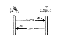
次に、本発明の例示的実施例による、メンバ登録に相当するセッション動作シナリオを説明する。図7は、本発明の例示的実施例による、セッション開始プロトコル(SIP)を用いてテレビ会議セッションに対して登録する方法を示す図である。図7の例はテレビ会議クライアント・アプリケーション(クライアント)702及びテレビ会議サーバ(サーバ)205を含む。本明細書及び特許請求の範囲の原文における句「client application」及び「client」は交換できるよう用いられている。 Next, a session operation scenario corresponding to member registration according to an exemplary embodiment of the present invention will be described. FIG. 7 is a diagram illustrating a method for registering for a video conference session using a Session Initiation Protocol (SIP), according to an illustrative embodiment of the invention. The example of FIG. 7 includes a video conference client application (client) 702 and a video conference server (server) 205. The phrases “client application” and “client” in the present specification and claims are used interchangeably.
メンバ登録機能においては、クライアント702はサーバ205に対してSIP REGISTER要求を送信する(工程710)。サーバ205はこのメッセージを受信してメンバ・データベース314においてクライアント702のIPアドレス及びSIP URLを記憶する。
In the member registration function, the
REGISTER要求はメッセージ本体を含み得るが、その使用は標準では規定されていない。メッセージ本体はサーバ205と登録するクライアント702の構成オプションに関する追加情報を含み得る。
A REGISTER request may include a message body, but its use is not specified by the standard. The message body may include additional information regarding configuration options for the
サーバ205は200OKメッセージをクライアント702に返信することによって登録を受信確認する(工程720)。
次に、本発明の例示的実施例による、ユニキャスト及びマルチキャストのテレビ会議セッションを説明する。図1B及び1Cは各々、本発明の2つの例示的実施例による、ユニキャストのテレビ会議セッション及びマルチキャストのテレビ会議セッションを示す構成図である。図1B及び1Cの例はクライアント1 130、クライアント2 132、クライアント3 134、イーサネット(登録商標)スイッチ136、IPルータ138、及びIPルータ140、及びWAN142を含む。
Next, unicast and multicast video conference sessions will be described according to an exemplary embodiment of the present invention. 1B and 1C are block diagrams illustrating a unicast video conference session and a multicast video conference session, respectively, according to two exemplary embodiments of the present invention. The examples of FIGS. 1B and 1C include
ユニキャストの例においては、一意のストリームが各クライアントから各々の他方のクライアントに送信される。そのようなアプローチによれば、更に多くの参加者がネットワークに参加するにつれて、多くの帯域を費やし得る。対照的に、マルチキャスト・アプローチにおいては、1つのストリームのみが各クライアントから送信される。したがって、マルチキャスト・アプローチはユニキャスト・アプローチと比較すると費やす、帯域のような、ネットワークのリソースは少なくなる。 In the unicast example, a unique stream is sent from each client to each other client. With such an approach, more bandwidth can be spent as more participants join the network. In contrast, in the multicast approach, only one stream is sent from each client. Thus, the multicast approach consumes less network resources, such as bandwidth, than the unicast approach.
次に、本発明の例示的実施例による、設定されるユニキャスト・テレビ会議セッションに相当するセッション動作シナリオを説明する。図8Aは本発明の例示的実施例による、セッション開始プロトコル(SIP)を用いてユニキャスト・テレビ会議セッションを設定する方法を示す図である。図8Aの例はテレビ会議クライアント・アプリケーション#1(クライアント#1)802、テレビ会議サーバ(サーバ)205及びテレビ会議クライアント・アプリケーション#2(クライアント#2)806を含む。 Next, a session operation scenario corresponding to a set unicast video conference session according to an exemplary embodiment of the present invention will be described. FIG. 8A is a diagram illustrating a method for setting up a unicast videoconference session using Session Initiation Protocol (SIP), according to an illustrative embodiment of the invention. The example of FIG. 8A includes a video conference client application # 1 (client # 1) 802, a video conference server (server) 205, and a video conference client application # 2 (client # 2) 806.
INVITE要求はクライアント#1 802からサーバ205に送信される(工程810)。INVITE要求はサーバ205からクライアント#2 806に対して転送される(工程815)。
The INVITE request is transmitted from
180呼び出しメッセージがクライアント#2 706からサーバ205に対して送信される(工程820)。180呼び出しメッセージはサーバ205からクライアント#1 702に転送される(工程825)。
A 180 call message is sent from
200OKメッセージはクライアント#2 706からサーバ205に対して送信される(工程830)。200OKメッセージはサーバ205からクライアント#1 702に対して転送される(工程835)。
The 200 OK message is transmitted from
受信要求メッセージACKがクライアント#1 702からクライアント#2 706に対して送信される(工程840)。テレビ会議セッション(メディア・セッション)は2つのノード(クライアント#1 802及び#2 806)間で行われる(工程845)。
A reception request message ACK is transmitted from
図8Bは、本発明の例示的実施例による、INVITE要求がテレビ会議クライアント・アプリケーション#1 802から受信される場合(図8Aの工程810)、テレビ会議サーバがたどる工程を示す図である。
FIG. 8B is a diagram illustrating the steps followed by a video conference server when an INVITE request is received from video conference
サーバ205は当初、要求ユーザ(クライアント#1 802)がサーバ205に登録されているかを確かめて、更に、呼び出されているユーザ(クライアント#2 806)がサーバ205に登録されているかを確かめる(工程850)。
The
サーバ205はネットワーク上の各ユーザの場所を判定して(工程855)(場所が異なる場合)2つの場所を接続している低帯域WANリンク(例えば、WAN250)があるかを判定する(工程860)。
2つの場所をお互いに接続する低帯域リンクのWANがない場合には、サーバ205はコールを進める(工程865)。しかしながら、2つのユーザの間で低帯域リンクがある場合には、方法は工程870に進む。
If there is no low bandwidth link WAN connecting the two locations to each other, the
工程870では、サーバ205がWAN250上のテレビ会議セッションについてのポリシーを確かめる;これは基本的には「Xセッションが最大ビットレートYで行い得る」と言い換えられる。サーバ205はこのポリシーに基づいて利用可能性を確かめる(工程875)。利用可能性がない場合、サーバ205は以下の如何なるメッセージ:「600−どこでも動作中」、「486−ここでは動作中」、「503−サービス利用不能」、又は「603−拒否」;を送信することによってもINVITE要求が却下されて(工程880)、当該方法は(図8Aの方法の工程815に続くことなく)終了する。しかしながら、利用可能性がある場合、サーバ205はコールを進める(工程865)。工程865は図8Aの方法の工程815に続く。
In
図9は更に、本発明の例示的実施例による、図8Aの方法を示す図である。図9の例はクライアント・アプリケーション1 998、クライアント・アプリケーション2 997、テレビ会議サーバ205、及び他のテレビ会議サーバ986を含む。図9にも表すテレビ会議サーバ205の構成部分はメンバ・データベース314、アクティブ・セッション・データベース312、ネットワーク・アーキテクチャ・データベース316に含まれるポリシー・データベース999、セッション・マネージャ320、SIPモジュール304d、及びサーバ間管理モジュール304eを含む。
FIG. 9 further illustrates the method of FIG. 8A, according to an illustrative embodiment of the invention. The example of FIG. 9 includes
図9はテレビ会議サーバ205内部での相互作用を表すよう設けるものであるので、テレビ会議サーバ205のエンティティ間の通知フローの例を設けるよう基本レベルのみで表すものである。
Since FIG. 9 is provided so as to represent the interaction within the
INVITE要求はテレビ会議サーバ205内部でクライアント・アプリケーション1 998からSIPモジュール304dに対して送信される(工程903)。SIPモジュール304dはメッセージを復号化してINVITE要求をセッション・マネージャ320に対して転送する(工程906)。セッション・マネージャ320は、セッションが正しく設定されることを徹底するよう、ネットワーク・アーキテクチャ・データベース316内部でアクティブ・セッション・データベース312、メンバ・データベース314、及びポリシー・データベース999を確かめる(各々、工程909、912、及び915)。セッションが正しく設定され得る場合、アクティブ・セッション・データベース312、メンバ・データベース314、及びポリシー・データベース999はOKメッセージをセッション・マネージャ320に対して送信する(工程918、921、及び924)。この検証処理が完了すると、テレビ会議サーバ205はシステム・ステータスにおける変更を他のビデオ会議サーバに通知する(工程927及び930)。
The INVITE request is transmitted from the
セッション・マネージャ320はINVITEメッセージをSIPモジュール304dに転送して(工程933)更にINVITEメッセージをクライアント2 997に転送する(工程936)。INVITEメッセージを受信すると、クライアント・アプリケーション2 997はSIPモジュール304dがINVITEメッセージを受信したことを示す180呼び出しメッセージによってSIPモジュール304dに応答する(工程939)。180呼び出しメッセージはSIPモジュール304dによって受信され、復号化されて更にセッション・マネージャ320に転送される(工程942)。クライアントのステータスが更新される(工程945、948,951、954、957、及び958)が、それはテレビ会議サーバ205内部の図9に表すデータベース各々においてである。
180呼び出しメッセージはセッション・マネージャ320からクライアント・アプリケーション1 998に転送される(工程960及び963)。200OKメッセージは更に、クライアント・アプリケーション2 997からSIPモジュール304dに送信されて(工程966)SIPモジュール304dからセッション・マネージャ320に転送される(工程969)。200OKメッセージはクライアント・アプリケーション2 997がテレビ会議セッションに対するインビテーションを受理することを示す。
The 180 call message is forwarded from
クライアントのステータスがテレビ会議サーバ205内部の図9に表すデータベース各々において更新される(工程972、975、978、981、984、及び985)。OKメッセージがセッション・マネージャ320からSIPモジュール304dに送信されてSIPモジュール304dからクライアント・アプリケーション1 998に転送される(工程988及び991)。ACKメッセージがクライアント・アプリケーション1 998からクライアント・アプリケーション2 987に送信されてセッション設定を完了する(工程994)。
The client status is updated in each of the databases represented in FIG. 9 inside the video conference server 205 (
次に、本発明の例示的実施例による、マルチキャスト・テレビ会議セッション設定に相当するセッション動作シナリオを説明する。マルチキャスト・セッション設定を設けるよう、セッション記述プロトコル(SDP)が用いられる。SDPプロトコルはマルチキャスト・アドレス及びポート番号を伝達することができる。 Next, a session operation scenario corresponding to a multicast video conference session setup according to an exemplary embodiment of the present invention will be described. Session description protocol (SDP) is used to provide multicast session settings. The SDP protocol can carry a multicast address and port number.
マルチキャスト・セッション設定は、マルチキャスト・アドレスを必要とする以外は、ユニキャスト・セッション設定と類似したものである。マルチキャスト・アドレスはネットワークにおけるMADCAPサーバ215によって割り当てられる。
Multicast session setup is similar to unicast session setup except that it requires a multicast address. The multicast address is assigned by the
図10は本発明の別の例示的実施例による、セッション開始プロトコル(SIP)を用いてマルチキャスト・テレビ会議セッションを設定する方法を示す図である。図10の例はテレビ会議クライアント・アプリケーション#1(クライアント#1)1002、テレビ会議サーバ(サーバ)205、テレビ会議クライアント・アプリケーション#2(クライアント#2)1006及びMADCAPサーバ215を含む。
FIG. 10 is a diagram illustrating a method for setting up a multicast videoconference session using Session Initiation Protocol (SIP), according to another exemplary embodiment of the present invention. The example of FIG. 10 includes a video conference client application # 1 (client # 1) 1002, a video conference server (server) 205, a video conference client application # 2 (client # 2) 1006, and a
INVITE要求はクライアント#1 1002からサーバ205に送信される(工程1010)。MADCAP要求はサーバ205からMADCAPサーバ215に送信される(工程1015)。受信確認メッセージACKはMADCAPサーバ215からサーバ205に送信される(工程1020)。INVITE要求はサーバ205からクライアント#2 1006に転送される(工程1025)。
The INVITE request is transmitted from the
180呼び出し・メッセージがクライアント#2 1006からサーバ205に送信される(工程1030)。180呼び出しメッセージがサーバ205からクライアント#1 1002に転送される(工程1035)。
A 180 call message is sent from
200OKメッセージがクライアント#2 1006からサーバ205に送信される(工程1040)。200OKメッセージがサーバ205からクライアント#1 1002に転送される(工程1045)。
A 200 OK message is transmitted from
受信確認メッセージACKがクライアント#1 1002からクライアント#2 1006に送信される(工程1050)。テレビ会議セッション(メディア・セッション)は2つのノード(クライアント#1 1002及びクライアント#2 1006)の間で行われる(工程1055)。
An acknowledgment message ACK is transmitted from
次に、本発明の例示的実施例による、テレビ会議セッションの取り消しに相当するセッション動作シナリオを説明する。CANCELメッセージは一時停止セッション設定試行を終了するのに用いられる。クライアントは、クライアントが以前に開始した一時停止テレビ会議セッション設定試行を取り消すよう、このメッセージを用い得る。サーバはINVITEが送信された一時停止要求と同じ場所に対してCANCELメッセージを転送する。クライアントは「200OK」メッセージによってCANCELメッセージに対して応答すべきでない。CANCELメッセージが正常でない場合、セッション終了シーケンス(例えば、BYEメッセージ)を用い得る。 Next, a session operation scenario corresponding to cancellation of a video conference session according to an exemplary embodiment of the present invention will be described. The CANCEL message is used to end a pause session setup attempt. The client may use this message to cancel a pause videoconference session setup attempt previously initiated by the client. The server forwards the CANCEL message to the same location as the pause request where INVITE was sent. The client should not respond to the CANCEL message with a “200 OK” message. If the CANCEL message is not normal, a session termination sequence (eg, BYE message) may be used.
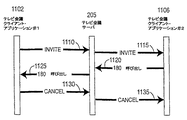
図11は本発明の例示的実施例による、セッション開始プロトコル(SIP)を用いてテレビ会議セッションを取り消す方法を示す図である。図11の例はテレビ会議クライアント・アプリケーション#1(クライアント#1)1102、テレビ会議サーバ(サーバ)205、及びテレビ会議クライアント#2(クライアント#2)1106を含む。 FIG. 11 is a diagram illustrating a method for canceling a video conference session using Session Initiation Protocol (SIP), according to an illustrative embodiment of the present invention. The example of FIG. 11 includes a video conference client application # 1 (client # 1) 1102, a video conference server (server) 205, and a video conference client # 2 (client # 2) 1106.
INVITE要求がクライアント#1 1102からサーバ205に送信される(工程1110)。INVITE要求がサーバ205からクライアント#2 1106に転送される(工程1115)。
An INVITE request is sent from
180呼び出しメッセージがクライアント#2 1106からサーバ205に送信される(工程1120)。180呼び出しメッセージがサーバ205からクライアント#2 1102に転送される(工程1125)。
A 180 call message is sent from
CANCELメッセージがクライアント#1 1102からサーバ205に送信される(工程1130)。CANCELメッセージがサーバ205からクライアント#2 1106に転送される(工程1135)。
A CANCEL message is sent from
次に、本発明の例示的実施例による、テレビ会議セッションの終了に相当するセッション動作シナリオを説明する。図12は本発明の例示的実施例による、セッション開始プロトコル(SIP)を用いて2つのクライアント間のテレビ会議セッションを終了する方法を示す図である。図12の例は第1クライアント(テレビ会議クライアント・アプリケーション#1)1202、テレビ会議サーバ(サーバ)205、及び第2クライアント(テレビ会議クライアント・アプリケーション#2)1206を示す。 Next, a session operation scenario corresponding to the end of a video conference session according to an exemplary embodiment of the present invention will be described. FIG. 12 is a diagram illustrating a method for terminating a videoconference session between two clients using Session Initiation Protocol (SIP), according to an illustrative embodiment of the present invention. The example of FIG. 12 shows a first client (video conference client application # 1) 1202, a video conference server (server) 205, and a second client (video conference client application # 2) 1206.
クライアント#1 1202はクライアント#2 1206とのコールを停止することを決定する。したがって、クライアント#1 1202はBYEメッセージをサーバ205に送信する(工程1210)。サーバ205はBYEメッセージをクライアント#2 1206に転送する(工程1220)。
クライアント#2 1206は、クライアント#2 1206が切断したことを示す200OKメッセージをサーバ205に返信する(工程1230)。サーバ205はクライアント#1 1202に対して切断が正常であることを示す200OKメッセージを転送する(工程1240)。
図13は本発明の例示的実施例による、セッション開始プロトコル(SIP)を用いて3つのクライアント間のテレビ会議セッションを終了する方法を示す図である。図13の例は第1クライアント(テレビ会議クライアント・アプリケーション#1)1302、テレビ会議サーバ(サーバ)205、第2クライアント(テレビ会議クライアント・アプリケーション#2)1306、及び第3クライアント(テレビ会議クライアント・アプリケーション#3)1308を含む。 FIG. 13 is a diagram illustrating a method for terminating a video conference session between three clients using Session Initiation Protocol (SIP), according to an illustrative embodiment of the present invention. The example of FIG. 13 shows a first client (video conference client application # 1) 1302, a video conference server (server) 205, a second client (video conference client application # 2) 1306, and a third client (video conference client Application # 3) 1308 is included.
クライアント#1 1302はクライアント#2 1306及びクライアント#3 1308とのコールを停止することを決定する;これはクライアント#2 1306とクライアント#3 1308との間のセッションをティア・ダウンするものでない。
クライアント#1 1302はBYEメッセージをサーバ205に送信する(工程1310)。サーバ205はBYEメッセージを解釈してクライアント#2 1306及びクライアント#3 1308がクライアント#1 1302とのテレビ会議セッションに関与していることがわかってBYEメッセージをクライアント#2 1306とクライアント#3 1308との両方に転送する(工程1320及び1330)。
クライアント#2 1306はサーバ205に200OKメッセージを返信する(工程1340)。サーバ205は200OKメッセージをクライアント#1 1302まで転送し戻す(工程1350)。クライアント#3 1308は200OKメッセージをサーバ205に返信する(工程1360)。サーバ205は200OKメッセージをクライアント#1 1302に転送し戻す(工程1370)。
図14は、本発明の別の例示的実施例によって、セッション開始プロトコル(SIP)を用いて3つのクライアント間のテレビ会議セッションを終了する方法を示す図である。図14の例は第1クライアント(テレビ会議クライアント・アプリケーション#1)1402、テレビ会議サーバ(サーバ)205、第2クライアント(テレビ会議クライアント・アプリケーション#2)1406、及び第3クライアント(テレビ会議クライアント・アプリケーション#3)1406を含む。 FIG. 14 is a diagram illustrating a method for terminating a video conference session between three clients using a Session Initiation Protocol (SIP) according to another exemplary embodiment of the present invention. The example of FIG. 14 shows a first client (video conference client application # 1) 1402, a video conference server (server) 205, a second client (video conference client application # 2) 1406, and a third client (video conference client Application # 3) 1406 is included.
クライアント#1 1402はクライアント#2 1406及びクライアント#3 1406とのコールを停止することを決定する;これはクライアント#2 1406とクライアント#3 1406との間のセッションをティア・ダウンするものでない。
クライアント#1 1402はクライアント#2 1406向けを企図したBYEメッセージをサーバ205に送信する(工程1410)。サーバ205はBYEメッセージをクライアント#2 1406に転送する(1420)。クライアント#1 1402はクライアント#3 1406向けを企図したBYEメッセージをサーバ205に送信する。サーバ205はBYEメッセージをクライアント#3 1406に転送する(工程1440)。
クライアント#2 1406は200OKメッセージをサーバ205に返信する(工程1450)。サーバ205は200OKメッセージをクライアント#1 1402に転送し戻す(工程1460)。クライアント#3 1408は200OKメッセージをサーバ205に返信する(工程1470)。サーバ205は200OKメッセージをクライアント#1 1402に転送し戻す(工程1480)。
図12乃至14による上記の例に加えて、終了は、テレビ会議加入者が関係するマルチキャスト・グループ・アドレスに対してBYEメッセージを送信することによって起動し得る。この方法を用いて、サーバ及び他のクライアント・アプリケーションはメッセージを受信する。これは関連するオーバヘッドの量が少ないため、セッションを終了する更に普遍的で効率的なメカニズムである。 In addition to the above example according to FIGS. 12-14, termination can be triggered by sending a BYE message to the multicast group address to which the video conference subscriber is concerned. Using this method, the server and other client applications receive the message. This is a more universal and efficient mechanism for terminating a session due to the small amount of overhead involved.
次に、本発明の例示的実施例による、解像度及びフレーム・レート調整に相当する動作シナリオを説明する。テレビ会議はコンピュータ・ネットワーク上の異なる場所にいる数ユーザ間での生の、双方向対話型映像を送信することに関係する。リアル・タイム対話型映像は制約遅延を伴った情報を大量に送信することを必要とする。これによってテレビ会議システムが接続されるコンピュータ・ネットワークはセッションに関与するユーザ毎に十分な帯域及びサービス品質を設けなければならないことを必要とする。帯域はたまに、制限リソースになり得てサービス品質は常に全てのネットワークにおいて保証し得ないので、制約がいくらか存在する。私設企業ネットワークにおいては、サービス品質を保証することが考えられるが、大量の帯域を保証することが常に可能なわけではない。 Next, an operation scenario corresponding to resolution and frame rate adjustment according to an exemplary embodiment of the present invention will be described. Video conferencing involves transmitting live, interactive video between several users at different locations on a computer network. Real-time interactive video requires transmitting large amounts of information with constrained delays. This requires that the computer network to which the video conference system is connected must provide sufficient bandwidth and quality of service for each user involved in the session. Since bandwidth can sometimes be a limited resource and quality of service cannot always be guaranteed in all networks, there are some constraints. In private enterprise networks, it is conceivable to guarantee service quality, but it is not always possible to guarantee a large amount of bandwidth.
基本企業コンピュータ・ネットワーク・インフラストラクチャは低速リンクを通じてお互いに接続された、いくつかの高速ローカル・エリア・ネットワーク(LAN)を含む(例えば、図2参照。)。高速LAN各々は通常、単一の地理的場所でのネットワーク・インフラストラクチャを表して低速リンクは複数の物理的場所をお互いに接続する長距離リンクである。低速リンクが用いられるのは、長距離リンクのコストが比較的高くて更にネットワーク・トラフィックのほとんどが通常、ローカル・エリア・ネットワーク内部で局所化されているので、大量のデータは通常、これらの長距離リンク上で交換されることがないからである。 The basic enterprise computer network infrastructure includes several high speed local area networks (LANs) connected to each other through low speed links (see, for example, FIG. 2). Each high speed LAN typically represents a network infrastructure at a single geographic location, and a low speed link is a long distance link that connects multiple physical locations together. Low speed links are used because the cost of long-distance links is relatively high and most network traffic is usually localized within the local area network, so large amounts of data are usually used for these long links. This is because they are not exchanged on the distance link.
IPベースのネットワーク上のサービス品質における昨今の発展によって、今日では、他の種類の情報がこれらのネットワークを越えて送信されることを可能にする手段を設けている。これは非リアル・タイム・データ・トラフィックに加えてリアル・タイム情報(すなわち、オーディオ及び映像)を、インフラストラクチャを越えて、送信することを可能にする。ネットワークのサービス品質を利用するテレビ会議サービスはこのインフラストラクチャにオーバレイするのに良く適している。更に、リアル・タイムのテレビ会議セッションにおいて2ユーザが2つの異なる物理的場所にいることが考えられる。テレビ会議セッションの1つの欠点にはリアル・タイム映像を伝送することによって極めて大量の帯域を費やして容易に、利用可能なネットワークを使い果たすことがあり得る。ネットワークを越えて伝送されるリアル・タイム映像のビットレートは主に、用いられる映像解像度及び圧縮アルゴリズムに左右される。一般に、異なる地理的場所での2、3、又は4ユーザ間の一テレビ会議セッションは適量の帯域のあるネットワーク上でサポートし得る。しかしながら、一般に、テレビ会議セッションにおける4を超える数の追加ユーザはサポートし得ないし、帯域の制約が理由で第2のテレビ会議セッションもサポートし得ない。テレビ会議システムの制限要因は地理的場所間の低速長距離リンクである。 With recent developments in quality of service on IP-based networks, nowadays there are provisions that allow other types of information to be transmitted across these networks. This allows real-time information (ie audio and video) to be transmitted across the infrastructure in addition to non-real-time data traffic. Video conferencing services that take advantage of network quality of service are well suited for overlaying this infrastructure. Further, it is possible that two users are in two different physical locations in a real-time video conference session. One shortcoming of video conferencing sessions can be that the available network can be easily exhausted by consuming a very large amount of bandwidth by transmitting real-time video. The bit rate of real time video transmitted over the network depends mainly on the video resolution and compression algorithm used. In general, a single video conference session between two, three, or four users at different geographical locations may be supported on a network with a reasonable amount of bandwidth. However, in general, more than four additional users in a video conference session cannot be supported, nor can a second video conference session be supported due to bandwidth constraints. The limiting factor of video conferencing systems is the low speed long distance link between geographic locations.
1つの考えられる解決策は当該システムにおいて更に多くのユーザをサポートするよう2つの地理的場所間での長距離リンクの帯域を増やすことである。このアプローチの欠点は帯域が非常に高価であることである。第2の解決策はテレビ会議セッションにおける限定数のユーザ(すなわち、アクティブ・ユーザ)のみが高解像度及び高ビットレートで伝送することが可能で、セッションにおける残りのユーザ(すなわち、パッシブ・ユーザ)は限定ビットレート及び限定解像度でしか伝送し得ない、システムを有することである。テレビ会議セッション運営者はどのユーザが高解像度で伝送してどのユーザが低解像度で伝送するかを左右する。ユーザがセッションにおいて能動的に話したり対話したりしていなければ、映像を高解像度で送信する必要はない。そのようなアプローチは帯域における多大な節減を設け得る。 One possible solution is to increase the bandwidth of the long distance link between the two geographical locations to support more users in the system. The disadvantage of this approach is that the bandwidth is very expensive. The second solution is that only a limited number of users (ie active users) in a video conference session can transmit at high resolution and high bit rate, and the remaining users (ie passive users) in the session are Having a system that can only transmit at a limited bit rate and limited resolution. Video conferencing session managers determine which users transmit at high resolution and which users transmit at low resolution. If the user is not actively speaking or interacting in the session, the video need not be transmitted at high resolution. Such an approach can provide significant savings in bandwidth.
次に図18Aのテレビ会議クライアント・アプリケーション1800による、このアプローチは、テレビ会議クライアント・アプリケーション1800における、種々のウィンドウ・サイズ(すなわち、高解像度及び低解像度復号化映像ストリームを表す異なるサイズの表示ウィンドウ)をサポートする、ユーザ・インタフェース1808及びサーバ205と他のクライアントのアプリケーションとの間の通信を規定する(図18Aのテレビ会議クライアント・アプリケーション1800に含まれたネットワーク・エンティティ1806に含まれた)メッセージング・システム1842を有することに関係する。メッセージング・システム1842はクライアントのアプリケーションの各々の符号化解像度及び送信ビットレートを制御するメッセージを含む。
Next, this approach, according to the videoconferencing client application 1800 of FIG. 18A, is based on various window sizes (ie, different sized display windows representing high and low resolution decoded video streams) in the videoconferencing client application 1800. A messaging interface (included in the
次に、本発明の例示的実施例による、解像度及びフレーム・レート調整に相当するメッセージについて説明する。特に、MSG_WINDOWS(登録商標)_SWITCHメッセージ及びMSG_ADJUST_CODECメッセージを説明する。 Next, messages corresponding to resolution and frame rate adjustments according to an exemplary embodiment of the present invention will be described. In particular, MSG_WINDOWS (registered trademark) _SWITCH message and MSG_ADJUST_CODEC message will be described.
アクティブ・ユーザとパッシブ・ユーザとの間の切り替えを示す、MSG_WINDOW_SWITCHメッセージはクライアントからサーバに送信される;すなわち、アクティブ・ユーザはパッシブになって、パッシブ・ユーザはアクティブになる。テレビ会議サーバはこの要求をクライアントと受信確認する。 An MSG_WINDOW_SWITCH message is sent from the client to the server indicating switching between active and passive users; that is, the active user becomes passive and the passive user becomes active. The video conferencing server acknowledges this request with the client.
MSG_ADJUST_CODECメッセージはサーバから各クライアントに送信される。MSG_ADJUST_CODECメッセージはクライアントがどの解像度(すなわち、CIF(共通中間フォーマット)又はQCIF(4分の1共通中間フォーマット)及びフレーム・レートで送信すべきかをクライアントに対して示す。MSG_ADJUST_CODECメッセージは各クライアントによって受信確認される。 The MSG_ADJUST_CODEC message is transmitted from the server to each client. The MSG_ADJUST_CODEC message indicates to the client what resolution (ie, CIF (Common Intermediate Format) or QCIF (Quarter Common Intermediate Format) and frame rate) the client should send. Is done.
図15は本発明の例示的実施例による、解像度及びフレーム・レート調整の通知方法を示す図である。図15の例はテレビ会議サーバ(サーバ)205、クライアント1 1504、クライアント2 1506、クライアント3 1508、及びクライアント4 1510を含む。
FIG. 15 is a diagram illustrating a notification method of resolution and frame rate adjustment according to an exemplary embodiment of the present invention. The example of FIG. 15 includes a video conference server (server) 205,
MSG_WINDOW_SWITCHメッセージはクライアント1 1504からサーバ205に送信される(工程1520)。受信確認メッセージACKがサーバ205からクライアント1 1504に送信される(工程1525)。
The MSG_WINDOW_SWITCH message is sent from
MSG_ADJUST_CODEC(低)メッセージはサーバ205からクライアント1 1504に送信される(工程1530)。受信確認メッセージACKがクライアント1 1504からサーバ205に送信される(工程1535)。
The MSG_ADJUST_CODEC (low) message is sent from
MSG_ADJUST_CODEC(高)メッセージがサーバ205からクライアント2 1506に送信される(工程1540)。受信確認メッセージACKがクライアント2 1506からサーバ205に送信される(工程1545)。
An MSG_ADJUST_CODEC (high) message is sent from
MSG_ADJUST_CODEC(低)メッセージがサーバ205からクライアント3 1508に送信される(工程1550)。受信確認メッセージACKがクライアント3 1508からサーバ205に送信される(工程1555)。
An MSG_ADJUST_CODEC (low) message is sent from
MSG_ADJUST_CODEC(低)メッセージがサーバ205からクライアント4 1510に送信される(工程1560)。受信確認メッセージACKがクライアント4 1510からサーバ205に送信される(工程1565)。
An MSG_ADJUST_CODEC (low) message is sent from
図16は、本発明の例示的実施例による、解像度及びフレーム・レート調整前の通知(クライアント2及び3)を示す図である。図17は、本発明の例示的実施例による、解像度及びフレーム・レート調整後の通知(クライアント2及び3)を示す図である。図16及び17の例はクライアント1 1602、クライアント2 1604、ネットワーク・ルータ1606、クライアント3 1608、及びクライアント4 1610を含む。
FIG. 16 is a diagram illustrating notifications (
「低ビットレート/解像度での送信」メッセージはクライアント1 1602からネットワーク・ルータ1606に送信される(工程1620)。「高ビットレート/解像度での送信」メッセージはクライアント3 1608からネットワーク・ルータ1606に送信される(工程1625)。「低ビットレート/解像度での送信」メッセージはクライアント2 1604からネットワーク・ルータ1606に送信される(工程1630)。「高ビットレート/解像度での送信」メッセージはクライアント4 1610からネットワーク・ルータ1606に送信される(工程1635)。
A “send at low bit rate / resolution” message is sent from
データはネットワーク・ルータ1606からクライアント2 1604、クライアント3 1608、クライアント1 1602、及びクライアント4 1610に、マルチキャスト・アドレスを用いて送信される(工程1640、1645、1650、及び1655各々)
図17に進むと、「低ビットレート/解像度での送信」メッセージはクライアント1 1602からネットワーク・ルータ1606に送信される(工程1720)。「高ビットレート/解像度での送信」メッセージはクライアント3 1608からネットワーク・ルータ1606に送信される(工程1725)。「高ビットレート/解像度での送信」メッセージはクライアント2 1604からネットワーク・ルータ1606に送信される(工程1630)。「低ビットレート/解像度での送信」メッセージはクライアント4 1610からネットワーク・ルータ1606に送信される(工程1635)。
Data is sent from the
Proceeding to FIG. 17, a “send at low bit rate / resolution” message is sent from
データはネットワーク・ルータ1606からクライアント2 1604、クライアント3 1603、クライアント1 1602、及びクライアント4 1610に、マルチキャスト・アドレスを用いて送信される(工程1740、1745、1750、及び1755各々)
次に、本発明の例示的実施例による、クライアント・アプリケーション・アーキテクチャを説明する。クライアント・アプリケーションはユーザと相互作用し、マルチメディア・コンテンツを他のクライアント・アプリケーションと交換して、サーバ・アプリケーションとのコールを管理する役目を担う。図18Aは本発明の例示的実施例による、テレビ会議クライアント・アプリケーション1800の構成図である。テレビ会議クライアント・アプリケーション1800はコンピュータ220a乃至fの何れか及び/又はコンピュータ230a乃至cの何れかのようなコンピュータ上で見出し得ることがわかる。
Data is sent from the
The client application architecture will now be described according to an exemplary embodiment of the present invention. The client application is responsible for interacting with the user and exchanging multimedia content with other client applications to manage calls with the server application. FIG. 18A is a block diagram of a video conference client application 1800, according to an illustrative embodiment of the invention. It will be appreciated that the videoconferencing client application 1800 may be found on a computer such as any of the
テレビ会議クライアント・アプリケーション1800は以下の4つの基本機能エンティティ:マルチメディア・インタフェース層1802;コデック1804(オーディオ・コデック1804a及びビデオ・コデック1804b);ネットワーク・エンティティ1806;及びユーザ・インタフェース1808;を含む。
Video conferencing client application 1800 includes the following four basic functional entities:
マルチメディア・インタフェース層1802はテレビ会議クライアント・アプリケーション1800の主制御インスタンスである。全てのシステム内通信はマルチメディア・インタフェース層1802を通じて送られて該層によって制御される。マルチメディア・インタフェース層1802の基礎をなす重要な特徴は異なるオーディオ及びビデオ・コデック1804を容易に交換し得ることである。これに加えて、マルチメディア・インタフェース層1802はオペレーティング・システム(OS)依存ユーザ入出力エンティティ及びネットワーク・サブ・システムに対するインタフェースを設ける。マルチメディア・インタフェース層1802はメンバ・データベース1820、主制御モジュール1822、オーディオ・ミキサ1899、及びエコー・キャンセレーション・モジュール1898を含む。
The
ユーザ・インタフェース1808はエンド・ユーザがテレビ会議クライアント・アプリケーションと相互作用するポイントを設ける。ユーザ・インタフェース1808はOS依存モジュールとして実施されることが好適であるが、必ずしもそうでなくてよい。多くのグラフィカル・ユーザ・インタフェースは使用している特定のOSに左右される。ユーザ・インタフェース1808の4つの主要機能は映像キャプチャ、映像表示、オーディオ・キャプチャ、及びオーディオ再生である。ユーザ・インタフェース1808はオーディオ/映像キャプチャ・インタフェース1830、オーディオ/映像再生モジュール1832、メンバ・ビュー・モジュール1834、チャット・モジュール1836、及びユーザ選定/メニュー1838を有する。オーディオ/映像キャプチャ・インタフェース1830はカメラ・インタフェース1830a、マイクロフォン・インタフェース1830b、及びファイル・インタフェース1830cを含む。オーディオ/映像再生モジュール1834は映像表示1832a、オーディオ再生モジュール1832b、及びファイル・インタフェース1832cを含む。
ネットワーク・エンティティ1806はテレビ会議クライアント・アプリケーション1800の通信サブ・システムを表す。ネットワーク・エンティティ1806の役目はセッション開始プロトコル(SIP)に基づいてクライアントからサーバにメッセージングしてオーディオ及び映像ストリームを送受信することにある。ネットワーク・エンティティ1806は更に、クライアント間でのメディア・ストリームの認証及び暗号化通信に関する基本的なセキュリティ機能も含む。ネットワーク・エンティティ1806はセキュリティ・モジュール1840、メッセージング・システム1842、映像ストリーム・モジュール1844、オーディオ・ストリーム・モジュール1846、及びIPソケット1848a乃至cを含む。
オーディオ・コデック1804a及びビデオ・コデック1804bはディジタル・メディアの圧縮及び復元を扱うサブ・システムである。コデックに対するインタフェースはそれらの間の交換を容易にするよう簡単で汎用であるべきである。マルチメディア・インタフェース層1802とコデック1804との間の簡単な関係を以降、実施における例示的テンプレート又はガイドとして規定する。オーディオ・コデック1804a及びビデオ・コデック1804bは各々符号器1880及び復号器1890を含む。符号器1880及び復号器1890各々はキュー1895を含む。
テレビ会議クライアント・アプリケーション1800は、少なくとも、テレビ会議サーバ205及び他のクライアント1870とインタフェースする。
The video conference client application 1800 interfaces with at least the
次に、本発明の例示的実施例による、図18Aのマルチメディア・インタフェース層1802に含まれるメンバ・データベース1820を説明する。メンバ・データベース1820はセッション毎に各参加ユーザについての情報を記憶する。メンバ・データベース1820は送受信IPアドレス、クライアント処理能力、特定のコデックについての情報、及びいろいろなユーザのステータスについての詳細を含む。上記の項目は単に例示的なものであるので、上記の項目の一部若しくは全部に加えた他の項目又は上記の項目の一部若しくは全部の代わりの他の項目を、本発明の精神及び範囲を維持しながら、メンバ・データベース1820に保持し得る。メンバ・データベース1820に含まれる情報はオーディオ及び映像復号器1890行きの着信情報を制御するのに用いられる。ネットワークから着信するメディア情報は正しいオーディオ及び映像復号器1890に送られる必要がある。同様に重要なことは、オーディオ及び映像符号器1890から来るメディア情報は配信するよう正しいユニキャスト又はマルチキャスト・アドレスに対して送られる必要がある。メンバ・データベース1820に含まれる基本情報は更に、エンド・ユーザがセッションにおける参加者及び処理能力について知っているようユーザ・インタフェース1808に送られる。INVITE要求がテレビ会議サーバ205から受信されると直ちに、ユーザがメンバ・データベース1820に追加されてBYE要求がテレビ会議サーバ205から受信されると直ちにユーザが取り除かれる。メンバ・データベース1820はセッションが終了すると消去される。
The
次に、本発明の例示的実施例による、図18Aのマルチメディア・インタフェース層1802に含まれる主制御モジュール1822を説明する。
The
主制御モジュール1822はマルチメディア・インタフェース層1802の非常に重要な部分である。主制御モジュール1822は中央管理サブ・システムとしての役割を果たして以下の主要な機能:オーディオ及び映像復号器及び再生に関する同期化メカニズム;復号器の行き先の画面又は記録目的でのファイルとの接続;及びアプリケーション層サービス品質;を設ける。
The
オーディオ及び映像再生の同期化は最適なビデオ会議ユーザ経験にとって欠かすことができない。2つのメディア・ストリームを正確に同期化するよう、タイムスタンプを用いてメディア・コンテンツとともに送信する必要がある。リアル・タイム・プロトコル(RTP)はこの目的でタイムスタンプ及び連番を含める汎用ヘッダを設ける。該設けるタイムスタンプは2つのネットワーク・ノード・クロックを同期化するよう企図されているものではないが、一致して再生するようオーディオ及び映像ストリームを同期化するよう企図されているものである。これらのタイムスタンプはキャプチャ時に同じノード上の共通クロックから導き出される必要がある。例えば、映像フレームがキャプチャされた場合、映像フレームがキャプチャされた時間を記録しなければならない。オーディオについても同様である。RTPを用いる詳細及び指針は更に、本明細書及び特許請求の範囲において別途、記載する。 Synchronization of audio and video playback is essential for an optimal video conferencing user experience. In order to accurately synchronize the two media streams, it needs to be transmitted with the media content using a time stamp. The Real Time Protocol (RTP) provides a general header that includes a time stamp and sequence number for this purpose. The provided time stamp is not intended to synchronize the two network node clocks, but is intended to synchronize the audio and video streams to play in a consistent manner. These timestamps need to be derived from a common clock on the same node at the time of capture. For example, when a video frame is captured, the time when the video frame was captured must be recorded. The same applies to audio. Details and guidelines for using RTP are further described elsewhere in the specification and claims.
オーディオ及び映像を同期化する主制御モジュール1822の役目は(タイムスタンプ及び連番を含む)メタデータを適切に配信するようネットワーク・エンティティ1806及びコデック1804間の接続を行うことにある。パケットが遅延した場合、システムの現行の状態に応じて復号化前又は後に取り去り得る。RTPタイムスタンプはその後、表示及び再生タイムスタンプを生成するよう用い得る。
The role of the
主制御モジュール1822は更に、再生するよう画面に、記録するようファイルに、又は両方に、オーディオ及び映像復号器1890の出力を向ける役割を果たす。各復号器1890は無関係に扱われるので、例の場合において、1つの復号器の出力が画面に表示されて、第2復号器の出力がファイルにおいて記録されて、第3復号器からの出力が同時にファイル及び画面に達することを可能にする。
The
上記の役割に加えて、主制御モジュール1822は更にアプリケーション層のサービス品質に関係する。主制御モジュール1822はパケット破棄、送受信バイトに関する情報を収集して、この情報に基づいて適宜、動作する。これはネットワークにおいて発生している状況を改善するのを助力するよう別のクライアント又はテレビ会議サーバ205に対してメッセージを送信することに関係し得る。リアル・タイム制御プロトコル(RTCP)は統計及びパケット喪失を通知するのに用い得、更にアプリケーション特有通知にも用い得る。
In addition to the above roles, the
図18Bは、本発明の例示的実施例による、図18Aのマルチメディア・インタフェース層1802に含まれるオーディオ・ミキサ1899を更に示す構成図である。オーディオ・ミキサ1899はここでは「利得制御モジュール」とも呼ばれ、複数のオーディオ復号器1890に動作するよう結合される。複数のオーディオ復号器1880は圧縮オーディオ・ストリームを受信して非圧縮オーディオ・ストリームを出力する。非圧縮オーディオ・ストリームはオーディオ・ミキサ1899に入力されて合成オーディオ・ストリームとして出力される。
18B is a block diagram further illustrating an
図18Cは本発明の例示的実施例による、更に、図18Aのマルチメディア・インタフェース層1802に含まれるエコー・キャンセレーション・モジュール1898を示す図である。エコー・キャンセレーション・モジュール(更にここでは「エコー・キャンセラ」と呼ぶ)1898はスピーカ1897(例えば、オーディオ再生モジュール1832b)及びマイクロフォン1896(例えば、マイクロフォン・インタフェース1830b)に動作するよう結合される。スピーカ1897からの音が全2重又は双方向通信システムにおいて生成される場合、局所のリスナからのみ聴かれることが企図されている。しかしながら、生成音は更に、局所マイクロフォン1896によって聴かれるので、信号が遠端に返信されることが可能になってエコーとして聴かれる。このために、テレビ会議クライアント・アプリケーション1800はエコー・キャンセレーション・モジュール1898にこの影響を軽減することを要求するので、更に良いユーザ経験をもたらす。
18C is a diagram further illustrating an
次に、本発明の例示的実施例による、テレビ会議クライアント・アプリケーション1800のサブ・システムが利用可能なインタフェースを説明する。該インタフェースはユーザ・インタフェース1808、ネットワーク・エンティティ1806、及びコデック1804との相互作用のポイントを含む。ユーザ・インタフェース1808はキャプチャされたオーディオ及び映像をそれらに相当するタイムスタンプとともに受信する機能を設ける。これに加えて、表示して再生するようユーザ・インタフェース1808に対してオーディオ及び映像を送信する機能を設けなければならない。ネットワーク・エンティティ1806インタフェースはセッション制御及びセキュリティ用着信及び発信メッセージを通知する機能を設ける。オーディオ及びビデオ・コデック1804a、bは構成制御用基本インタフェースを設けるとともに、圧縮又は復元するようパケットを送信又は受信する。
The interfaces available to the video conferencing client application 1800 subsystem according to an exemplary embodiment of the present invention will now be described. The interface includes points of interaction with
次に、本発明の例示的実施例による、オーディオ及びビデオ・コデック1804a、bを説明する。
Next, an audio and
テレビ会議において利用可能なオーディオ及びビデオ・コデック1804a、bはいくつかある。本発明によって使用されるコデックはソフトウェア・ベースのものであることが好適であるが、必ずしもそうでなくてよい。本発明の一例示的実施例によれば、典型的なデスクトップ・コンピュータの処理能力制約が理由で、H.263が映像圧縮及び復元に用いられる。デスクトップ・コンピュータが将来更に強力になるにつれて、H.26Lのような更に高度なコデックを用いることができることが実現し得て利用し得る。当然、本発明は上記の種類のコデックに限定されるものでなく、他の種類のコデックを、本発明の精神及び範囲を維持しながら、用い得る。
There are several audio and
次に、本発明の例示的実施例による、コデック1804a、bに対するインタフェースを説明する。該説明はData Inファンクション、呼び戻しファンクション、及びコデックのオプションを包含する。コデック1804a、bに対するインタフェースは、コデックを相互に交換できることを可能にして将来において更に、新しいコデックを追加することを可能にするよう、十分柔軟で一般的に規定されているべきである。この柔軟で汎用的なインタフェースを実施する当該企図されたインタフェースはユーザに設けられるファンクションの数が限定された非常に簡単なインタフェースである。
The interface to
Data Inファンクションは単に、符号器又は復号器クラスのフレーム又はパケットを記憶するのに用いられる。 The Data In function is simply used to store an encoder or decoder class frame or packet.
マルチメディア・インタフェース層1802とマルチメディア・コデック1804との間の簡単な接続を設けるよう、データ出力ファンクションは呼び戻しとして実施すべきである。マルチメディア・インタフェース層1802はこの呼び戻しファンクションを受信エンティティの入力ファンクションに設定する。例えば、コデックがフレームの符号化又は復号化を完了した場合、このファンクションが、符号化又は復号化処理からの企図された情報を配信するよう、コデックによって呼び出される。コデックがこの呼び戻し中には何もできない制約が理由で、このファンクションは、システムにおける待ち及び不必要な遅延を防止するよう、できるだけ速くリターンすべきである。このファンクションにおいて行うべき追加の待ちはただ、共有リソースをアクセスする場合のミューテックスのロックである。
The data output function should be implemented as a recall to provide a simple connection between the
利用可能なオプションの範囲はコデックの異なる種類によって変わってくる。これらのオプションを管理する要件を満たすよう、簡単なインタフェースを用いるべきである。テキスト・ベースのインタフェースが好適である(が必須ではない)がそれは設けられる柔軟性が理由である。START及びSTOPのような共通のコマンド群、更には、コデック特有コマンドがあるべきである。この方法は簡単なインタフェースを設けるが、簡単なインタプリタを要するのでコデックに対して更に複雑になる。例えば、オプション・ファンクションはオプションを読み書きするのに十分汎用であり得る:
例: 結果=オプション(「開始」);結果=オプション(「解像度=CIF」);など
例えば、コデック間の共通オプションのいくつかは以下:開始;停止;中断;品質指標(0−100);及び解像度;のように標準化すべきである。
The range of options available depends on the different types of codecs. A simple interface should be used to meet the requirements for managing these options. A text-based interface is preferred (but not required) because of the flexibility provided. There should be common commands such as START and STOP, as well as codec specific commands. This method provides a simple interface, but is more complicated for the codec because it requires a simple interpreter. For example, option functions can be generic enough to read and write options:
Example: result = option (“start”); result = option (“resolution = CIF”); etc. For example, some of the common options between codecs are: start; stop; interrupt; quality indicator (0-100); And resolution; should be standardized.
品質指標は0%と100%との間の値としてコデックの全般的な品質を表す率である。これは、値が高いほど映像品質が良いという前提に従うものである。 The quality index is a rate that represents the overall quality of the codec as a value between 0% and 100%. This is based on the premise that the higher the value, the better the video quality.
図19は本発明の例示的実施例による、オーディオ・コデック1804a及び/又は映像コデック1804bの何れかに含まれる復号器1890によって使用される方法を示す図である。該方法は復号器コンテキスト1901及び呼び出し側コンテキスト1902に関して説明する。該方法は少なくとも以下の入力及び出力:「データ入力」1999;「信号入力」1998;「信号出力呼び戻し」1997;「呼び戻しファンクション設定」1996;及び「データ出力呼び戻し」1995;を用いて動作する。入力「データ入力」1999は入力キューにデータを記憶するのに用いられる(工程1905)。
FIG. 19 is a diagram illustrating a method used by a
初期化工程(Init)は復号器1890を初期化するよう行われる(工程1910)。開始又は終了コマンドを待つ、主ループが実行される(工程1920)。終了コマンドが受信された場合、該方法は終了して(工程1922)リターンが、例えば、別の動作に対して、行われる(1924)。 An initialization step (Init) is performed to initialize the decoder 1890 (step 1910). A main loop is executed waiting for a start or end command (step 1920). If an end command is received, the method ends (step 1922) and a return is made, for example, for another operation (1924).
データが入力キュー1895から読み出されるか、入力キュー1895が空き状態の場合、待ち状態が課される(工程1930)。データは、工程1930で読み出された場合は、復号化される(工程1940)。「データ出力呼び戻し」1995は工程1920に設けられる。
If data is read from the
次に、本発明の例示的実施例による、ネットワーク200によって使用される通信を説明する。該説明はネットワーク通信に関して上記に設けたものを補足する。
The communications used by
(図18Aのネットワーク・エンティティ1806に含まれた)メッセージング・システム1842はテレビ会議クライアント・アプリケーション1800とテレビ会議サーバ205との間のインタフェースを設ける。これはセッション管理(すなわち、セッション設定及びティア・ダウン)に用いられる。全ての通知メッセージはテレビ会議サーバ205を通じて、クライアントからクライアントに直接ではなく、通知される。マルチメディア・コンテンツ及びプラーベート・チャット・メッセージのようなデータはクライアント間で直接送信される唯一の情報を構成する。メッセージング・システムは標準ベースのセッション開始プロトコル(SIP)を用いる。
Messaging system 1842 (included in
テレビ会議クライアント・アプリケーション1800の機能を支配する異なるプロトコルはいくつかある。例えば、セッション開始プロトコル(SIP)、リアル・タイム・プロトコル(RTP)、リアル・タイム制御プロトコル(RTCP)、及びセッション記述プロトコル(SDP)を使用し得る。 There are several different protocols that govern the functionality of the video conference client application 1800. For example, Session Initiation Protocol (SIP), Real Time Protocol (RTP), Real Time Control Protocol (RTCP), and Session Description Protocol (SDP) may be used.
セッション開始プロトコル(SIP)の目的はセッション管理である。SIPはIPベース・ネットワーク上の一以上の参加者とのマルチメディア・セッションの生成、修正、及び終了を行うテキスト・ベースのアプリケーション層制御プロトコルである。SIPはこれを実現するようクライアントとサーバとの間で用いられる。SIPは更に、テレビ会議サーバ205に関して上記に説明されている。
The purpose of the Session Initiation Protocol (SIP) is session management. SIP is a text-based application layer control protocol that creates, modifies, and terminates multimedia sessions with one or more participants on an IP-based network. SIP is used between the client and server to achieve this. SIP is further described above with respect to
リアル・タイム・プロトコル(RTP)はリアル・タイムのマルチメディア(すなわち、オーディオ及び映像)の伝送に用いられる。 RTPは伝達するマルチメディア情報の種類に関して更に詳細を設けるアプリケーション層プロトコルである。RTPはトランスポート層の上にあって通常、ユーザ・データグラム・プロトコル(UDP)の上で伝達される。クライアント・アプリケーションにおけるRTPの主要な役目は(オーディオ及び映像を同期化する)タイムスタンプ、連番、をトランスポートすること及びカプセル化するペイロードの種類(例えば、MPEG4、H.263、G.723など)を識別することにある。 The Real Time Protocol (RTP) is used for transmission of real time multimedia (ie, audio and video). RTP is an application layer protocol that provides further details regarding the type of multimedia information being transmitted. RTP is above the transport layer and is usually carried over User Datagram Protocol (UDP). The main role of RTP in client applications is to transport timestamps (synchronizing audio and video), serial numbers, and the type of payload to encapsulate (eg MPEG4, H.263, G.723, etc.) ) To identify.
図20は、本発明の例示的実施例による、ユーザ・プレーン・プロトコル・スタック2000を示す図である。該スタック2000は1つの層上に映像2010及び音声2020、別の層上に映像2010及び音声2020の両方のRTP2030、更に別の層上にUDPポート#x2040及びUDPポート#Y2050、IP層2060、リンク層2070、及び物理層2080を含む。コデック特有RTPヘッダは汎用RTPヘッダに加えて用いられる。
FIG. 20 is a diagram illustrating a user
リアル・タイム制御プロトコル(RTCP)はRTP要求の一部である。RTCPは送信者及び受信者間の統計通知ツールとして用いられる。各テレビ会議クライアント・アプリケーション1800は統計を収集してそれらをお互いに、更に、サーバ205に対して、送信する。テレビ会議サーバ205はこのデータに基づいてセッションにおいて発生したかもしれない問題に関する情報を記録する。
The Real Time Control Protocol (RTCP) is part of the RTP request. RTCP is used as a statistical notification tool between a sender and a receiver. Each video conference client application 1800 collects statistics and sends them to each other and to the
図21は、本発明の例示的実施例による、制御プレーン・プロトコル・スタック2100を示す図である。該スタック2100は1つの層上のSIP2110、UI(ユーザ・インタフェース)コデック変更メッセージング2120、RTCP2130、TCP層2140、IP層2150、リンク層2160、及び物理層2170を含む。
FIG. 21 is a diagram illustrating a control
SDPの主な目的はセッションのメディア・ストリームについての情報を伝達することにある。SDPは以下のもの:セッション名及び目的;セッションが実行中の時間;セッションを有するメディア;メディアを受信する情報(すなわち、アドレス、ポート、フォーマットなど);メディアの種類;トランスポート・プロトコル(RTP/UDP/IP);メディアのフォーマット(H.263など);マルチキャスト;メディア用マルチキャスト・アドレス;メディア用トランスポート・ポート;ユニキャスト;及びメディア用遠隔アドレス;を含むがそれらには限定されない。 The main purpose of SDP is to convey information about the media stream of a session. The SDP includes: session name and purpose; time the session is running; media with the session; information to receive the media (ie, address, port, format, etc.); media type; transport protocol (RTP / Media format (such as H.263); multicast; multicast address for media; transport port for media; unicast; and remote address for media;
SDP情報はSIPメッセージに対するメッセージ本体である。それらは一緒に送信される。 The SDP information is a message body for the SIP message. They are sent together.
次に、本発明の例示的実施例による、図18Aのユーザ・インタフェース1808を説明する。ユーザ・インタフェース1808はテレビ会議クライアント・アプリケーション1800の非常に重要な構成部分である。ユーザ・インタフェース1808はいくつかのビュー(表示/ボタン/メニュー/…)を含み、全ての入力データ(オーディオ/映像キャプチャ、ボタン、キーストローク)を扱い得る。
The
図22は、本発明の例示的実施例による、図18Aのユーザ・インタフェース1808に相当するスクリーン・ショット2200を示す構成図である。スクリーン・ショット2200は「大ビュー」2210、「小ビュー」2220、チャット・ビュー部2230、メンバ・ビュー部2240、及びチャット編集部2250を含む。
FIG. 22 is a block diagram illustrating a
もう一度図18Aによれば、映像キャプチャ・インタフェース1830は以下の如何なるもの:ウェブ・カム(図なし);キャプチャ・カード及び高品質カメラ(図なし);カメラ・インタフェース1830a;マイクロフォン・インタフェース1830b;ファイル・インタフェース1830c;などをも含み得る。
Referring again to FIG. 18A, the video capture interface 1830 can be any of the following: a web cam (not shown); a capture card and a high quality camera (not shown); a
ウェブ・カムはウィンドウズ(登録商標)・オペレーティング・システムによって設けられたビデオ・フォー・ウィンドウズ(登録商標)(VFW)アプリケーション・プログラミング・インタフェース(API)を用いたUSB(ユニバーサル・シリアル・バス)又はファイアワイヤ(IEEE(米国電気電子学会)1394)を通じて又はリナックスのような別のオペレーティング・システム下で用いられる別のキャプチャ・ドライバを通じてサポートすべきである。当然、本発明は上記のインタフェース、オペレーティング・システム、又はドライバに限定されるものでないので、他のインタフェース、オペレーティング・システム、及びドライバも、本発明の精神及び範囲を維持しながら、用い得る。 Web cam is USB (Universal Serial Bus) or Fire using the Video for Windows (VFW) application programming interface (API) provided by the Windows operating system Should be supported through wire (IEEE (Institute of Electrical and Electronics Engineers) 1394) or through another capture driver used under another operating system such as Linux. Of course, since the present invention is not limited to the interfaces, operating systems, or drivers described above, other interfaces, operating systems, and drivers may be used while maintaining the spirit and scope of the present invention.
メンバ・ビュー・モジュール1834は進行中のコールに参加しているメンバに対して表示するのに用いられる。コールの起動者(すなわち、マスタ)は所望しないメンバを取り去るかアクティブなメンバを選定するかの何れかを行い得る。全てのメンバがプライベート・チャット・メッセージ交換に1人以上のメンバを選定し得る。更に、メンバのステータスはメンバ・ビュー・モジュール1834に通知される。メンバは更に、自らのステータスを、例えば、現在は不在であるが直ぐに戻る旨を他方に通知するよう、「不在」に、設定し得る。 The member view module 1834 is used to display to members participating in an ongoing call. The call initiator (i.e., master) can either remove the unwanted member or select an active member. All members may select one or more members for private chat message exchange. In addition, member status is communicated to member view module 1834. Members may further set their status, for example, “absent” to notify the other that they are currently absent but will return soon.
映像ストリームに加えて、各メンバはチャット・モジュール1836を用いて他の全てのメンバか一部のメンバかの何れかに対してチャット・メッセージを送信する機会がある。メッセージはチャット・ビューに表示されてチャット編集ビューにおいて編集される。スクロールバーは更に古いメッセージを視ることを可能にする。 In addition to the video stream, each member has the opportunity to send a chat message to either all other members or some members using the chat module 1836. Messages are displayed in the chat view and edited in the chat edit view. The scroll bar allows you to view older messages.
次に、本発明の例示的実施例による、クライアント・アプリケーション1800の動作シナリオを説明する。以下の説明は単に、クライアント・アプリケーション1800の特徴の一部の基本的な指針であって特徴の完全な一覧を表すことを企図するものでない。該説明はログ・イン、コールの開始、コールの受理、及びログ・オフを包含する。 Next, an operation scenario of the client application 1800 will be described according to an exemplary embodiment of the present invention. The following description is merely a basic guideline for some of the features of the client application 1800 and is not intended to represent a complete list of features. The description includes log-in, call initiation, call acceptance, and log-off.
ログ・インはクライアント・アプリケーション1800が当初開始される場合に行われる。ログ・インは起動時にオペレーティング・システムに設けられるログ・イン名に基づいて自動的に行われるか、ログ・インに無関係で異なるインタフェースを用い得る。現在用いられているネットワークに対する認証の好適的方法及びポリシーがどのように実行されているかによって変わってくる。最も簡単な方法は命名の一貫性を維持して(該当する場合)既存のユーザ・データベースを再使用することができるようウィンドウズ(登録商標)・オペレーティング・システムにおいて用いられるのと同様なログ・イン名を用いる。 Log in occurs when the client application 1800 is initially started. Log-in can be done automatically based on the log-in name provided in the operating system at startup, or a different interface can be used regardless of log-in. It depends on how the preferred method and policy of authentication for the currently used network is implemented. The simplest method is to log in similar to that used in the Windows operating system so that naming consistency can be maintained (if applicable) and the existing user database can be reused. Use a name.
図23は、本発明の例示的実施例による、ログ・イン・インタフェース2300を示す図である。サイン・アップ機能2330はユーザがサーバ上で現在アカウントを有していない場合に用いられる。電子メール・アドレスは簡単にアクセスするよう如何なる電子メール・アドレス入力ボックス2340にも設け得る。
FIG. 23 is a diagram illustrating a log-in
コールを始動するには、クライアント・アプリケーション1800は利用可能な候補者のリストをサーバ205に問い合わせる。クライアントはテレビ会議セッションに引き入れたいユーザを選定し得る。セッションは参加者2者が関係する場合にユニキャストとして設定される;さもなければ、2者を超える参加者が関係する場合、セッションはマルチキャスト・セッションとして設定される。
To initiate a call, client application 1800 queries
図24は、本発明の例示的実施例による、セッションを開始するユーザ選定インタフェース2400を示す構成図である。
FIG. 24 is a block diagram illustrating a
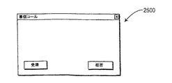
ユーザがコールにインバイトされると、起動者の名前を表すメッセージが画面上に表示される。ユーザは更に、コールを受理するか却下するかの何れかを行い得る。ユーザがコールを受理する場合、クライアント・アプリケーション1800は受理(又は受信確認)メッセージをサーバ205に送信する。サーバ205は更に新規メンバに関してコールに現在参加している全てのメンバに通知する。ユーザがサーバ205に取り消しメッセージを送信することによってコールを拒否する場合、他のメンバも全てそのイベントについて通知される。図25は、本発明の例示的実施例による、着信コールを受理又は却下するインビテーション・インタフェース2500を示す構成図である。
When the user is invited into the call, a message representing the name of the initiator is displayed on the screen. The user can further either accept or reject the call. If the user accepts the call, the client application 1800 sends an acceptance (or acknowledgment) message to the
ログ・オフはテレビ会議サーバ205のデータベース・エンティティ302に含まれるメンバ・データベース314からユーザを除去する。BYEメッセージがセッションの各参加クライアントに送信される。これはマルチキャスト又はユニキャストの何れかを通じて行い得る。マルチキャストはこのメッセージを送信する好適的方法である。
Log off removes the user from the
例示的目的で、本発明の以下の説明を図2に表す例示的ネットワーク200に関して行う。しかしながら、本発明は図2に表す特定のネットワーク構成に限定されるものでないので、ネットワークの他の構成及び実施例を本発明によって、本発明の精神及び範囲を維持しながら、使用し得ることがわかる。
For exemplary purposes, the following description of the present invention will be made with respect to the
ネットワーク200を越えるトラフィックの種類(リアル・タイム・トラフィック及び非リアル・タイム・トラフィック)に差異を設けることはLAN225、235をWAN250にインタフェースするルータ240、245で行い得る。これらのルータ240,245の内部には、ソース及び行き先インターネット・プロトコル(IP)アドレス、ユーザ・データグラム・プロトコル/伝送制御プロトコル(UDP/TCP)ポート番号などのようなトラフィックに差異を設ける基礎を備えるよう用い得る特定の基準を有するフィルタが存在し得る。本発明はテレビ会議時間予約システムに基づいてこれらのトラフィック分類フィルタを動的に設定するメカニズムを設ける。
Differentiating the type of traffic (real-time traffic and non-real-time traffic) across the
テレビ会議システムにおいては、時間予約システムが一般にテレビ会議システムを用いるよう時間帯を予約するのに使用される。しかしながら、テレビ会議システムを用いるのに時間帯を予約する時間予約システムを使用するのに加えて、本発明によるテレビ会議システムは効果的にサービス品質契約を作成して更にフィルタ基準(例えば、テレビ会議の特定メンバ)をテレビ会議セッションの時間帯について設ける。QoS契約及びトラフィック分類フィルタは、予約時間帯に達するまでWAN250を越えてお互いに2つのLAN225,235を接続するルータ240,245には達しない。予約時間帯が終わると、QoS契約及びフィルタはWAN250を越えて2つのLAN225、235を接続するルータ240、245から取り去られる。例えば、テレビ会議セッションが特定の日の1:00PMと2:00PMの間で予約された場合、テレビ会議サーバ205はWAN250を越えた2つのクライアント間でのテレビ会議セッションに対する適切なサポートを設けるようこの特定時間においてQoS契約及びフィルタを動的に設定する。
In video conferencing systems, time reservation systems are generally used to reserve time slots to use video conferencing systems. However, in addition to using a time reservation system that reserves a time zone to use a video conference system, the video conference system according to the present invention effectively creates a quality of service contract and further filters criteria (eg, video conference). Specific members of the video conference session). The QoS contract and the traffic classification filter do not reach the
ルータ225、235はWAN250に対するエントリ・ポイントを設けて、本発明の例示的実施例によれば、これがQoS契約及びフィルタが形成されるところである。これによってルータ225、235は映像トラフィックがWAN250に達した場合に適切に取り扱うことを可能にする。映像トラフィックはWAN250を越えて送信するのに必要な帯域を得て、更に未使用帯域が残っている場合にはベスト・エフォート型データ・サービスに割り当てられる。
図26は本発明の例示的実施例によって、テレビ会議セッションに関するサービス品質(QoS)契約及びトラフィック分類フィルタを設定する方法を示す流れ図である。該方法はテレビ会議セッションに対する時間予約に基づくものである。該方法はテレビ会議クライアント・コンピュータ#1(クライアント・コンピュータ#1)2602、テレビ会議クライアント・コンピュータ#2(クライアント・コンピュータ#2)2604、テレビ会議サーバ205、ルータ#1 240、及びルータ#2 245に関係する。該例においては、クライアント・コンピュータ#1のユーザはテレビ会議セッションの起動クライアントである。
FIG. 26 is a flow diagram illustrating a method for setting a quality of service (QoS) contract and a traffic classification filter for a video conference session according to an exemplary embodiment of the present invention. The method is based on a time reservation for a video conference session. The method includes a video conference client computer # 1 (client computer # 1) 2602, a video conference client computer # 2 (client computer # 2) 2604, a
クライアント・コンピュータ#1 2602及びクライアント・コンピュータ#2 2604は当初、テレビ会議サーバ205に登録する(工程2610a及び2610b)。工程2610a及び2610bはコンピュータ2602,2604が当初立ち上げられる時かある別の時に行い得る。登録中に設けられる情報はクライアント・コンピュータ#1 2602及びクライアント・コンピュータ#2 2604のIPアドレスを含む。IPアドレス各々は相当するクライアント・コンピュータを何らかのかたちで一意に特定する場所名又はコンピュータ名と関連付け得る;当然、該関連付けは省略してIPアドレスをそのまま使用しても良いが、それはIPアドレスが実際にはコンピュータを一意に、それが最もユーザ・フレンドリなフォーマットにおいてではないようだが、特定するからである。
クライアント・コンピュータ#1 2602のユーザはテレビ会議セッションに対する時間帯及び日付を予約する(工程2620)。予約時間帯及び日付が到来すると、構成情報がテレビ会議サーバ205からルータ240、245各々に送信される(工程2630a及び2630b)。構成情報は、例えば、シンプル・ネットワーク管理プロトコル(SNMP)、を用いてルータ240、245に送信し得る。当然、本発明はSNMPに限定されないものであるので、他のプロトコルも、本発明の精神及び範囲を維持しながら、使用し得る。構成情報はQoS契約及びトラフィック分類フィルタを含む。QoS契約はテレビ会議セッション・トラフィックによって要求される平均帯域を規定する。トラフィック分類フィルタはソースIPアドレス及び行き先IPアドレスを規定して更にリアル・タイム・トラフィック用のいくつかの特定のUDPポートを規定する。トラフィック分類フィルタは更に、IPヘッダに設定されたタイプ・オブ・サービス(ToS)フィールド・ビットのように簡単であり得る。本発明は上記の種類のトラフィック分類フィルタに限定されないものであるので、他の種類のトラフィック分類フィルタを使用し得る。すなわち、ここに設ける本発明の教示を前提にすれば、当業者は、本発明の精神及び範囲を維持しながら、これら及び種々の他の種類のトラフィック分類フィルタ及びそれに相当する情報を考案するものである。
The user of
テレビ会議セッションはQoS契約によって、テレビ会議セッションに対する帯域の保証を設けるトラフィック分類フィルタを用いて、実施される(工程2640)。 The video conference session is performed by a QoS contract using a traffic classification filter that provides a bandwidth guarantee for the video conference session (step 2640).
予約時間帯及び日付が満了すると(工程2645)、ルータ240、245各々が先行してそこに送信された構成情報を取り去るようテレビ会議サーバ205によって接触される(工程2650a、2650b)。
When the appointment window and date expire (step 2645), each
その代わりに、時間帯が満了すると直ちに構成情報を取り去る(工程2650による)代わりに、テレビ会議セッションを左右するテレビ会議アプリケーションはテレビ会議セッションが終了した場合にテレビ会議サーバ205に通知し得る(工程2647)。更に、工程2647の後に、工程2650が行われてルータ240,245各々が構成情報を取り去るようテレビ会議サーバによって接触される。この代替策によってテレビ会議セッションの長さにおいて更に大きな柔軟性を設け得る。
Instead, instead of removing the configuration information as soon as the time period expires (according to step 2650), the video conference application that governs the video conference session may notify the
図26の方法はテレビ会議セッションに対する単一トラフィック分類フィルタに関して説明されている一方、1つを超えるトラフィック分類フィルタをテレビ会議セッションに用い得る。例えば、1つのフィルタを、リアル・タイム・トラフィックを分類する/リアル・タイム・トラフィックに差異を設けるよう、用い得て、別のフィルタを、非リアル・タイム・トラフィックを分類する/非リアル・タイム・トラフィックに差異を設けるよう、用い得る。更に、図26の方法はルータに関して説明しているが、ネットワークの別のルーティング・エレメントを更に、用い得るので、本発明は単にルータに限定されない。ここに設ける本発明の教示を前提にすれば、当業者は、本発明の精神及び範囲を維持しながら、本発明のこれら及び種々の他の構成及び実施例を考案するものである。 While the method of FIG. 26 is described with respect to a single traffic classification filter for a video conference session, more than one traffic classification filter may be used for a video conference session. For example, one filter can be used to classify real-time traffic / differentiate real-time traffic, and another filter can be used to classify non-real-time traffic / non-real-time Can be used to make a difference in traffic. Furthermore, although the method of FIG. 26 is described with respect to a router, the present invention is not limited to just a router because additional routing elements of the network may be used. Given the teachings of the present invention provided herein, one of ordinary skill in the art will devise these and various other configurations and embodiments of the present invention while maintaining the spirit and scope of the present invention.
例示的実施例がここでは添付図面とともに説明されたが、本発明はまさにこれらの実施例に限定されるものでなく、種々の他の変更及び修正が当業者によって本発明の範囲又は精神から逸脱することなく、もたらされ得ることがわかる。これらの全ての変更及び修正は本特許請求の範囲によって規定された本発明の範囲内に含まれることが企図されている。 While exemplary embodiments have been described herein with reference to the accompanying drawings, the present invention is not limited to these embodiments, and various other changes and modifications can be made by those skilled in the art from the scope or spirit of the invention. It can be seen that this can be done without All these changes and modifications are intended to be included within the scope of the present invention as defined by the appended claims.
Claims (26)
該テレビ会議セッションについての時間帯に対する予約を受信する工程;及び
該ネットワークを横断する他のトラフィックからの該テレビ会議セッションに相当するリアル・タイム・トラフィックをフィルタするよう、該時間帯が予約された後に該ルーティング・エレメントの少なくとも1つに対して構成情報を送信する工程;
を有することを特徴とする方法。 In a network, a method for providing that a quality of service (QoS) contract for a video conference session between clients can be established, the network comprising a routing element that sends information through the network:
Receiving a reservation for a time zone for the video conference session; and the time zone is reserved to filter real time traffic corresponding to the video conference session from other traffic across the network. Later sending configuration information to at least one of the routing elements;
A method characterized by comprising:
前記テレビ会議セッションに対して前記クライアントを、サーバによって、登録する工程;
を有することを特徴とする方法。 The method of claim 1, further comprising:
Registering the client with the server for the video conference session;
A method characterized by comprising:
前記予約時間帯が満了すると前記構成情報を取り去るよう前記少なくとも1つの前記ルーティング・エレメントと接触する工程;
を有することを特徴とする方法。 The method of claim 1, further comprising:
Contacting the at least one routing element to remove the configuration information when the reserved time period expires;
A method characterized by comprising:
前記テレビ会議セッションが完了した場合に通知を受信する工程;及び
前記構成情報を取り去るよう前記少なくとも1つの前記ルーティング・エレメントと接触する工程;
を有することを特徴とする方法。 The method of claim 1, further comprising:
Receiving a notification when the video conference session is completed; and contacting the at least one routing element to remove the configuration information;
A method characterized by comprising:
該テレビ会議セッションについての時間帯に対する予約を受信する手段;及び
該ネットワークを横断する他のトラフィックからの該テレビ会議セッションに相当するリアル・タイム・トラフィックをフィルタするよう該時間帯が予約された後に該ルーティング・エレメントの少なくとも1つに対して構成情報を送信する手段;
を有することを特徴とするシステム。 In a network, a system providing that a quality of service (QoS) contract for a video conference session between clients can be established, the network having a routing element that sends information through the network:
Means for receiving a reservation for a time zone for the video conference session; and after the time zone is reserved to filter real-time traffic corresponding to the video conference session from other traffic across the network Means for transmitting configuration information to at least one of the routing elements;
The system characterized by having.
前記テレビ会議セッションに対して前記クライアントを登録する手段;
を有することを特徴とするシステム。 The system of claim 12, further comprising:
Means for registering the client for the videoconference session;
The system characterized by having.
前記予約時間帯が満了すると前記構成情報を取り去るよう前記少なくとも1つの前記ルーティング・エレメントと接触する手段;
を有することを特徴とするシステム。 The system of claim 12, further comprising:
Means for contacting the at least one routing element to remove the configuration information when the reserved time period expires;
The system characterized by having.
前記テレビ会議セッションが完了した場合に通知を受信する手段;及び
前記構成情報を取り去るよう前記少なくとも1つの前記ルーティング・エレメントと接触する手段;
を有することを特徴とするシステム。 The system of claim 12, further comprising:
Means for receiving a notification when the video conference session is completed; and means for contacting the at least one routing element to remove the configuration information;
The system characterized by having.
該テレビ会議セッションに対する予約を送信することができることを設ける工程;
を有し、該予約は該テレビ会議セッションについての時間帯を特定するので、クライアントが、該特定時間帯中に、保証されたサービス・レベルの該テレビ会議セッションに参加し得ることを特徴とする方法。 In a network, a method for providing that a quality of service (QoS) contract for a video conference session between clients can be established, the network comprising a routing element that sends information through the network:
Providing that a reservation for the videoconference session can be transmitted;
And the reservation specifies a time zone for the video conference session, so that a client can participate in the video conference session at a guaranteed service level during the specific time zone. Method.
前記ビデオ会議セッションに対して登録することができることを、前記クライアントの少なくとも1つに対して、設ける工程;
を有することを特徴とする方法。 24. The method of claim 23, further comprising:
Providing for at least one of the clients that it can register for the video conference session;
A method characterized by comprising:
いつ前記テレビ会議セッションが完了されたかの通知を送信することができることを設ける工程;
を有することを特徴とする方法。 24. The method of claim 23, further comprising:
Providing that a notification of when the video conference session is completed can be sent;
A method characterized by comprising:
Applications Claiming Priority (9)
| Application Number | Priority Date | Filing Date | Title |
|---|---|---|---|
| US34179701P | 2001-12-15 | 2001-12-15 | |
| US34180001P | 2001-12-15 | 2001-12-15 | |
| US34180101P | 2001-12-15 | 2001-12-15 | |
| US34172001P | 2001-12-15 | 2001-12-15 | |
| US34167101P | 2001-12-15 | 2001-12-15 | |
| US34179901P | 2001-12-15 | 2001-12-15 | |
| US34181901P | 2001-12-15 | 2001-12-15 | |
| US36633102P | 2002-03-20 | 2002-03-20 | |
| PCT/US2002/039528 WO2003052993A2 (en) | 2001-12-15 | 2002-12-11 | Quality of service setup on a time reservation basis |
Related Child Applications (1)
| Application Number | Title | Priority Date | Filing Date |
|---|---|---|---|
| JP2009029310A Division JP2009153172A (en) | 2001-12-15 | 2009-02-12 | Quality of service setup on time reservation basis |
Publications (1)
| Publication Number | Publication Date |
|---|---|
| JP2005513865A true JP2005513865A (en) | 2005-05-12 |
Family
ID=27575409
Family Applications (7)
| Application Number | Title | Priority Date | Filing Date |
|---|---|---|---|
| JP2003553771A Pending JP2005513865A (en) | 2001-12-15 | 2002-12-11 | Quality of service setting by time reservation system |
| JP2003553782A Pending JP2005513869A (en) | 2001-12-15 | 2002-12-11 | Video conference bandwidth selection mechanism |
| JP2003553430A Expired - Fee Related JP4091546B2 (en) | 2001-12-15 | 2002-12-12 | Video conference to switch from unicast to multicast |
| JP2003553783A Pending JP2005513870A (en) | 2001-12-15 | 2002-12-12 | Video conference call settings |
| JP2003553432A Pending JP2005534207A (en) | 2001-12-15 | 2002-12-13 | Video conferencing application user interface with messaging system |
| JP2003553808A Ceased JP2005513875A (en) | 2001-12-15 | 2002-12-13 | Method and system for providing a private conversation channel in a video conferencing system |
| JP2009029310A Pending JP2009153172A (en) | 2001-12-15 | 2009-02-12 | Quality of service setup on time reservation basis |
Family Applications After (6)
| Application Number | Title | Priority Date | Filing Date |
|---|---|---|---|
| JP2003553782A Pending JP2005513869A (en) | 2001-12-15 | 2002-12-11 | Video conference bandwidth selection mechanism |
| JP2003553430A Expired - Fee Related JP4091546B2 (en) | 2001-12-15 | 2002-12-12 | Video conference to switch from unicast to multicast |
| JP2003553783A Pending JP2005513870A (en) | 2001-12-15 | 2002-12-12 | Video conference call settings |
| JP2003553432A Pending JP2005534207A (en) | 2001-12-15 | 2002-12-13 | Video conferencing application user interface with messaging system |
| JP2003553808A Ceased JP2005513875A (en) | 2001-12-15 | 2002-12-13 | Method and system for providing a private conversation channel in a video conferencing system |
| JP2009029310A Pending JP2009153172A (en) | 2001-12-15 | 2009-02-12 | Quality of service setup on time reservation basis |
Country Status (8)
| Country | Link |
|---|---|
| US (5) | US20080158337A1 (en) |
| EP (6) | EP1454451A1 (en) |
| JP (7) | JP2005513865A (en) |
| KR (6) | KR100948317B1 (en) |
| CN (6) | CN1618071B (en) |
| AU (6) | AU2002357144A1 (en) |
| MX (6) | MXPA04005816A (en) |
| WO (6) | WO2003052993A2 (en) |
Families Citing this family (201)
| Publication number | Priority date | Publication date | Assignee | Title |
|---|---|---|---|---|
| WO2003081449A1 (en) * | 2002-03-20 | 2003-10-02 | Thomson Licensing S.A. | Videoconference system architecture |
| GB0230301D0 (en) * | 2002-12-30 | 2003-02-05 | Nokia Corp | Streaming media |
| US7360164B2 (en) * | 2003-03-03 | 2008-04-15 | Sap Ag | Collaboration launchpad |
| US20040228291A1 (en) * | 2003-05-15 | 2004-11-18 | Huslak Nicolas Steven | Videoconferencing using managed quality of service and/or bandwidth allocation in a regional/access network (RAN) |
| US8619630B2 (en) * | 2003-06-12 | 2013-12-31 | Camiant, Inc. | Topology discovery in broadband networks |
| US7146185B2 (en) * | 2003-06-12 | 2006-12-05 | Richard Lane | Mobile station-centric method for managing bandwidth and QoS in error-prone system |
| AU2004247251B2 (en) | 2003-06-12 | 2009-01-22 | Camiant, Inc. | PCMM application manager |
| CN100337430C (en) * | 2003-07-19 | 2007-09-12 | 华为技术有限公司 | A method for implementing exception wildcard |
| US7369493B2 (en) * | 2003-10-28 | 2008-05-06 | At&T Corp. | Congestion control in an IP network |
| US7778326B1 (en) | 2003-12-23 | 2010-08-17 | At&T Intellectual Property Ii, L.P. | System and method for dynamically determining multimedia transmission based on communication bandwidth |
| US20050265318A1 (en) * | 2004-01-08 | 2005-12-01 | Nokia Corporation | Apparatus, system, and method for rejecting a session establishment request |
| US20050154793A1 (en) * | 2004-01-08 | 2005-07-14 | Hisham Khartabil | Apparatus, system, and method for rejecting a session establishment request |
| EP1730898B1 (en) * | 2004-01-22 | 2011-06-08 | TELEFONAKTIEBOLAGET LM ERICSSON (publ) | Access control for multicast channel request |
| US20050188415A1 (en) | 2004-01-23 | 2005-08-25 | Camiant, Inc. | Video policy server |
| CA2554177C (en) * | 2004-01-23 | 2015-03-31 | Camiant, Inc. | Policy-based admission control and bandwidth reservation for future sessions |
| FR2866768A1 (en) * | 2004-02-19 | 2005-08-26 | France Telecom | Audio/video Internet protocol service accessing process for e.g. personal computer, involves determining and associating channel identifier to information provided to mediation module, and receiving identifier by terminal, from module |
| JP4049115B2 (en) * | 2004-03-15 | 2008-02-20 | セイコーエプソン株式会社 | projector |
| US7773581B2 (en) * | 2004-03-19 | 2010-08-10 | Ericsson Ab | Method and apparatus for conferencing with bandwidth control |
| US7062286B2 (en) * | 2004-04-05 | 2006-06-13 | Motorola, Inc. | Conversion of calls from an ad hoc communication network |
| KR20050099899A (en) * | 2004-04-12 | 2005-10-17 | 엘지전자 주식회사 | Allocation method for internet protocol multicast based universal plug and play network |
| JP4571437B2 (en) * | 2004-05-31 | 2010-10-27 | インターナショナル・ビジネス・マシーンズ・コーポレーション | System, method and program for displaying a plurality of windows having different resolutions |
| US7756594B2 (en) * | 2004-06-14 | 2010-07-13 | Microsoft Corporation | Systems and methods for parsing flexible audio codec topologies |
| KR100840365B1 (en) * | 2004-07-30 | 2008-06-20 | 삼성전자주식회사 | Method for merging session of Multiple Push To Talk over Cellular session and system thereof |
| US7590065B2 (en) * | 2004-08-04 | 2009-09-15 | Microsoft Corporation | Equal-opportunity bandwidth regulation |
| US20060031607A1 (en) * | 2004-08-05 | 2006-02-09 | Microsoft Corporation | Systems and methods for managing input ring buffer |
| CN100409683C (en) * | 2004-08-10 | 2008-08-06 | 中兴通讯股份有限公司 | Method for holding video conference on video operation platform |
| CN100417220C (en) * | 2004-09-28 | 2008-09-03 | 中兴通讯股份有限公司 | Method for holding multi-point video conference by terminal dialing |
| US7706901B2 (en) * | 2004-10-01 | 2010-04-27 | Microsoft Corporation | Low latency real-time audio streaming |
| US7256816B2 (en) | 2004-10-25 | 2007-08-14 | 3V Technologies Incorporated | Systems and processes for scheduling and conducting audio/video communications |
| KR100739489B1 (en) * | 2004-12-13 | 2007-07-13 | 한국전자통신연구원 | A Bandwidth Broker connects with router that belongs to network channel from server to client and differentiated service method thereof |
| CN100403794C (en) * | 2004-12-29 | 2008-07-16 | 华为技术有限公司 | Video terminal and method of implementing services of stream media |
| AU2005322970A1 (en) * | 2005-01-06 | 2006-07-13 | Tervela, Inc. | Hardware-based messaging appliance |
| US8249076B1 (en) * | 2005-01-14 | 2012-08-21 | Acme Packet, Inc. | Method, system and architecture for validating media sessions in networks that use communication protocols with distinct signaling and media channels |
| US7796603B1 (en) | 2005-01-14 | 2010-09-14 | Acme Packet, Inc. | Method and system for controlling media sessions in networks that use communication protocols with distinct signaling and media channels |
| CN100505864C (en) * | 2005-02-06 | 2009-06-24 | 中兴通讯股份有限公司 | Multi-spot video conference system and media processing method |
| US7558267B2 (en) * | 2005-02-11 | 2009-07-07 | Microsoft Corporation | Method and system for placing restrictions on sessions |
| US7716283B2 (en) * | 2005-02-16 | 2010-05-11 | Microsoft Corporation | Television system video conferencing |
| JP4700977B2 (en) * | 2005-02-16 | 2011-06-15 | 富士通株式会社 | Multipoint conference system |
| US7830409B2 (en) | 2005-03-25 | 2010-11-09 | Cherng-Daw Hwang | Split screen video in a multimedia communication system |
| AU2005334066A1 (en) * | 2005-06-30 | 2007-01-11 | Promim Pty Ltd | A system and method for controlling transmission and display of video |
| US8352853B2 (en) * | 2005-06-30 | 2013-01-08 | Motorola Mobility Llc | Composer circuit and method for encoding device independent multi-modal content |
| AU2006346226B8 (en) * | 2005-07-20 | 2010-03-25 | Vidyo, Inc. | System and method for a conference server architecture for low delay and distributed conferencing applications |
| CN100448228C (en) * | 2005-09-02 | 2008-12-31 | 杭州华三通信技术有限公司 | Method for multicasting message to traverse non multicasting network and its applied network system |
| JP4722656B2 (en) * | 2005-09-29 | 2011-07-13 | 京セラ株式会社 | Wireless communication apparatus and wireless communication method |
| KR100677497B1 (en) * | 2005-11-02 | 2007-02-02 | 엘지전자 주식회사 | Duplicated notification processing method in a terminal |
| US7889732B2 (en) * | 2005-12-22 | 2011-02-15 | Alcatel-Lucent Usa, Inc. | Method for converting between unicast sessions and a multicast session |
| US8436889B2 (en) * | 2005-12-22 | 2013-05-07 | Vidyo, Inc. | System and method for videoconferencing using scalable video coding and compositing scalable video conferencing servers |
| WO2007073319A1 (en) * | 2005-12-23 | 2007-06-28 | Operax Ab | Resource manager for media distribution in an ip network |
| CN100531381C (en) * | 2006-01-27 | 2009-08-19 | 中国科学院声学研究所 | The method for IPTV STB/unicast seamless switching based on RTP protocol |
| CN101030918B (en) * | 2006-03-03 | 2010-06-02 | 华为技术有限公司 | Method, apparatus and system for supplying packet service based on IP network |
| CN100428796C (en) * | 2006-03-13 | 2008-10-22 | 华为技术有限公司 | Video ordered telecasting method, system, server and terminal |
| JP4977385B2 (en) * | 2006-03-15 | 2012-07-18 | 日本電気株式会社 | Video conference system and video conference method |
| US8477662B2 (en) * | 2006-04-28 | 2013-07-02 | Vidcom Corporation | Court video teleconferencing system and method |
| US7983201B2 (en) * | 2006-05-09 | 2011-07-19 | Avaya Inc. | Coordinated invitations to a conference call |
| US8571012B2 (en) * | 2006-05-12 | 2013-10-29 | Oracle International Corporation | Customized sip routing to cross firewalls |
| US8582555B2 (en) * | 2006-05-12 | 2013-11-12 | Oracle International Corporation | SIP routing customization |
| CN101047748B (en) * | 2006-05-16 | 2011-09-14 | 华为技术有限公司 | Method of conference service |
| US7565616B2 (en) * | 2006-06-02 | 2009-07-21 | Hewlett-Packard Development Company, L.P. | System for controlling display content for multiple electronic display units |
| US7945620B2 (en) * | 2006-06-13 | 2011-05-17 | International Business Machines Corporation | Chat tool for concurrently chatting over more than one interrelated chat channels |
| US20070291108A1 (en) * | 2006-06-16 | 2007-12-20 | Ericsson, Inc. | Conference layout control and control protocol |
| US8284915B2 (en) * | 2006-06-30 | 2012-10-09 | At&T Intellectual Property Ii, L.P. | Method and apparatus for providing virtual closed circuit television |
| WO2008042852A2 (en) * | 2006-09-29 | 2008-04-10 | Vidyo, Inc. | System and method for multipoint conferencing with scalable video coding servers and multicast |
| TW200816707A (en) * | 2006-07-31 | 2008-04-01 | Ibm | System, method and computer program for transferring information on network |
| EP1887751A1 (en) * | 2006-08-11 | 2008-02-13 | Nokia Siemens Networks Gmbh & Co. Kg | Method and system for synchronizing at least two media streams within one push-to-talk-over-cellular session |
| US8817668B2 (en) * | 2006-09-15 | 2014-08-26 | Microsoft Corporation | Distributable, scalable, pluggable conferencing architecture |
| US8745496B2 (en) | 2006-09-21 | 2014-06-03 | Apple Inc. | Variable I/O interface for portable media device |
| US8956290B2 (en) | 2006-09-21 | 2015-02-17 | Apple Inc. | Lifestyle companion system |
| US8001472B2 (en) | 2006-09-21 | 2011-08-16 | Apple Inc. | Systems and methods for providing audio and visual cues via a portable electronic device |
| US8429223B2 (en) * | 2006-09-21 | 2013-04-23 | Apple Inc. | Systems and methods for facilitating group activities |
| US8235724B2 (en) | 2006-09-21 | 2012-08-07 | Apple Inc. | Dynamically adaptive scheduling system |
| US8576851B2 (en) * | 2006-09-22 | 2013-11-05 | Microsoft Corporation | Integrating data with conversations |
| US8249068B2 (en) * | 2006-10-20 | 2012-08-21 | Alcatel Lucent | Method and apparatus for establishing multicast groups |
| US8311197B2 (en) * | 2006-11-10 | 2012-11-13 | Cisco Technology, Inc. | Method and system for allocating, revoking and transferring resources in a conference system |
| US20080120370A1 (en) * | 2006-11-22 | 2008-05-22 | Brian Chan | Virtual Meeting Server Discovery |
| US10389762B2 (en) * | 2006-12-19 | 2019-08-20 | Bce Inc. | Method, system and apparatus for causing a communication client to join a media-over-packet communication session |
| JPWO2008105429A1 (en) * | 2007-02-27 | 2010-06-03 | 京セラ株式会社 | Communication terminal and control method thereof |
| CN101257395B (en) * | 2007-02-27 | 2010-12-08 | 中国移动通信集团公司 | System and method for supporting multimedia conference booking |
| US8631069B2 (en) * | 2007-03-01 | 2014-01-14 | Oracle International Corporation | Web and multi-media conference |
| US7701970B2 (en) * | 2007-04-10 | 2010-04-20 | International Business Machines Corporation | Protocol negotiation for a group communication system |
| US8243119B2 (en) | 2007-09-30 | 2012-08-14 | Optical Fusion Inc. | Recording and videomail for video conferencing call systems |
| WO2009063762A1 (en) * | 2007-11-12 | 2009-05-22 | Nec Corporation | Data communication system, method, and program |
| WO2009074081A1 (en) * | 2007-11-30 | 2009-06-18 | Huawei Technologies Co., Ltd. | Method, system and device for establishing broadcast or multicast bearer |
| EP2223538B1 (en) | 2007-12-17 | 2016-03-23 | Telefonaktiebolaget LM Ericsson (publ) | Method and arrangement for network qos |
| JP4516594B2 (en) * | 2007-12-27 | 2010-08-04 | 株式会社日立製作所 | Message transmission control method, message transmission control device, and message transmission control program |
| US8904031B2 (en) * | 2007-12-31 | 2014-12-02 | Genesys Telecommunications Laboratories, Inc. | Federated uptake throttling |
| KR101499549B1 (en) * | 2008-01-15 | 2015-03-06 | 삼성전자주식회사 | UPnP apparatus for providing remote access service and method thereof |
| US8379533B2 (en) * | 2008-01-15 | 2013-02-19 | Samsung Electronics Co., Ltd. | Universal plug and play method and apparatus to provide remote access service |
| US9113334B2 (en) | 2008-02-01 | 2015-08-18 | Tekelec, Inc. | Methods, systems, and computer readable media for controlling access to voice resources in mobile networks using mobility management signaling messages |
| US8229812B2 (en) | 2009-01-28 | 2012-07-24 | Headwater Partners I, Llc | Open transaction central billing system |
| US8832777B2 (en) | 2009-03-02 | 2014-09-09 | Headwater Partners I Llc | Adapting network policies based on device service processor configuration |
| US8589541B2 (en) | 2009-01-28 | 2013-11-19 | Headwater Partners I Llc | Device-assisted services for protecting network capacity |
| US8275830B2 (en) | 2009-01-28 | 2012-09-25 | Headwater Partners I Llc | Device assisted CDR creation, aggregation, mediation and billing |
| US20100005497A1 (en) * | 2008-07-01 | 2010-01-07 | Michael Maresca | Duplex enhanced quality video transmission over internet |
| US20150156455A1 (en) * | 2008-07-01 | 2015-06-04 | Michael J. Maresca, JR. | System and method for enabling realtime remote communication in the medical field |
| US8346923B2 (en) * | 2008-11-12 | 2013-01-01 | Sophos Plc | Methods for identifying an application and controlling its network utilization |
| NO332009B1 (en) * | 2008-12-12 | 2012-05-21 | Cisco Systems Int Sarl | Method of initiating communication connections |
| US8380790B2 (en) * | 2008-12-15 | 2013-02-19 | Microsoft Corporation | Video conference rate matching |
| US20100149301A1 (en) * | 2008-12-15 | 2010-06-17 | Microsoft Corporation | Video Conferencing Subscription Using Multiple Bit Rate Streams |
| US8149263B2 (en) * | 2009-01-21 | 2012-04-03 | Freeport Technologies | Distributed scheduling, call control, and resource management for dispersed dynamic video communications networks |
| US10798252B2 (en) | 2009-01-28 | 2020-10-06 | Headwater Research Llc | System and method for providing user notifications |
| US9706061B2 (en) * | 2009-01-28 | 2017-07-11 | Headwater Partners I Llc | Service design center for device assisted services |
| US9572019B2 (en) | 2009-01-28 | 2017-02-14 | Headwater Partners LLC | Service selection set published to device agent with on-device service selection |
| US9980146B2 (en) | 2009-01-28 | 2018-05-22 | Headwater Research Llc | Communications device with secure data path processing agents |
| US10264138B2 (en) | 2009-01-28 | 2019-04-16 | Headwater Research Llc | Mobile device and service management |
| US9565707B2 (en) | 2009-01-28 | 2017-02-07 | Headwater Partners I Llc | Wireless end-user device with wireless data attribution to multiple personas |
| US10237757B2 (en) | 2009-01-28 | 2019-03-19 | Headwater Research Llc | System and method for wireless network offloading |
| US10326800B2 (en) | 2009-01-28 | 2019-06-18 | Headwater Research Llc | Wireless network service interfaces |
| US9300708B2 (en) | 2009-02-05 | 2016-03-29 | Google Technology Holdings LLC | Connecting to a multimedia broadcast/multicast service channel |
| US9025927B2 (en) * | 2009-03-25 | 2015-05-05 | Cyberlink Corp. | Systems and methods of variable frame rate playback |
| US8977684B2 (en) * | 2009-04-14 | 2015-03-10 | Citrix Systems, Inc. | Systems and methods for computer and voice conference audio transmission during conference call via VoIP device |
| US8352600B2 (en) * | 2009-04-21 | 2013-01-08 | Alcatel Lucent | System and method for determining a maximum packet data unit (PDU) payload transmission size for communicating in a managed computer network system |
| US8437282B2 (en) * | 2009-06-21 | 2013-05-07 | Clearone Communications Hong Kong Limited | System and method of multi-endpoint data conferencing |
| WO2011003447A1 (en) * | 2009-07-08 | 2011-01-13 | Telefonaktiebolaget Lm Ericsson (Publ) | Session switching during ongoing data delivery in a network |
| CN101990083B (en) * | 2009-07-29 | 2014-04-09 | 宏碁股份有限公司 | Video conference signal processing system |
| CN101640787B (en) * | 2009-08-24 | 2011-10-26 | 中兴通讯股份有限公司 | Method and device for hierarchical control access of multicast group |
| US20110066745A1 (en) * | 2009-09-14 | 2011-03-17 | Sony Ericsson Mobile Communications Ab | Sharing video streams in commnication sessions |
| CN102055949B (en) * | 2009-11-02 | 2013-10-02 | 华为终端有限公司 | Recording method, device and system of multimedia conference and rewinding method and device |
| US8411129B2 (en) | 2009-12-14 | 2013-04-02 | At&T Intellectual Property I, L.P. | Video conference system and method using multicast and unicast transmissions |
| US8471890B1 (en) * | 2009-12-30 | 2013-06-25 | Insors Integrated Communications | Adaptive video communication channel |
| US9205328B2 (en) | 2010-02-18 | 2015-12-08 | Activision Publishing, Inc. | Videogame system and method that enables characters to earn virtual fans by completing secondary objectives |
| WO2011105780A2 (en) | 2010-02-23 | 2011-09-01 | Lg Electronics Inc. | A method and an apparatus for initiating a session in home network system |
| CN101795388A (en) * | 2010-04-07 | 2010-08-04 | 兴旺 | Visible talking method and system for buildings |
| US9682324B2 (en) | 2010-05-12 | 2017-06-20 | Activision Publishing, Inc. | System and method for enabling players to participate in asynchronous, competitive challenges |
| US8717409B2 (en) * | 2010-05-13 | 2014-05-06 | Lifesize Communications, Inc. | Conducting a direct private videoconference within a videoconference |
| US8717408B2 (en) * | 2010-05-13 | 2014-05-06 | Lifesize Communications, Inc. | Conducting a private videoconference within a videoconference via an MCU |
| JP5392185B2 (en) * | 2010-05-28 | 2014-01-22 | コニカミノルタ株式会社 | Video distribution system, server therefor, video distribution method, and computer program |
| US8947492B2 (en) * | 2010-06-18 | 2015-02-03 | Microsoft Corporation | Combining multiple bit rate and scalable video coding |
| US8576271B2 (en) * | 2010-06-25 | 2013-11-05 | Microsoft Corporation | Combining direct and routed communication in a video conference |
| CN102316301B (en) | 2010-06-29 | 2014-05-07 | 华为终端有限公司 | Method, system and device for switching conferences |
| CN101945245B (en) | 2010-09-06 | 2013-09-25 | 华为终端有限公司 | Realizing method, device and system of video conference application |
| KR20120047621A (en) * | 2010-11-04 | 2012-05-14 | 한국전자통신연구원 | System and method for multi-hop multiplex input-output |
| KR20120083820A (en) * | 2011-01-18 | 2012-07-26 | 삼성전자주식회사 | Method and apparatus for transmitting contents in contents transmission system |
| US20120259924A1 (en) * | 2011-04-05 | 2012-10-11 | Cisco Technology, Inc. | Method and apparatus for providing summary information in a live media session |
| NZ595638A (en) * | 2011-10-07 | 2013-09-27 | Let S Powow Ltd | Collaboration Extension System |
| CN102348168A (en) * | 2011-10-14 | 2012-02-08 | 华为终端有限公司 | Group calling method, terminal and application server |
| US9942580B2 (en) * | 2011-11-18 | 2018-04-10 | At&T Intellecutal Property I, L.P. | System and method for automatically selecting encoding/decoding for streaming media |
| CN102387049B (en) * | 2011-11-25 | 2014-02-19 | 浪潮电子信息产业股份有限公司 | Cloud service quality evaluation method based on SNMP (simple network management protocol) |
| KR101696321B1 (en) * | 2011-12-27 | 2017-01-13 | 한국전자통신연구원 | Video conference control system and method for reservation video conference |
| US20130238725A1 (en) * | 2012-03-12 | 2013-09-12 | Unisys Corporation | Chat and notification services for a web-based conference collaboration tool |
| US9369667B2 (en) * | 2012-04-11 | 2016-06-14 | Jie Diao | Conveying gaze information in virtual conference |
| JP2013251630A (en) * | 2012-05-30 | 2013-12-12 | Toshiba Corp | Information terminal and program |
| JP5949272B2 (en) * | 2012-07-25 | 2016-07-06 | 株式会社リコー | Communication system and program |
| US8767031B2 (en) * | 2012-08-20 | 2014-07-01 | Wolzien Llc | Video call center |
| CN102970091B (en) * | 2012-11-14 | 2015-06-10 | 深圳市欧博科技有限公司 | Device and method for implementing packet voice broadcasts |
| GB2511721A (en) * | 2012-12-06 | 2014-09-17 | Nec Corp | Communication system |
| NO336150B1 (en) * | 2012-12-19 | 2015-05-26 | Videxio As | Procedure and unit for optimizing large-scale video conferencing |
| JP6111753B2 (en) * | 2013-03-11 | 2017-04-12 | 株式会社リコー | Information processing device, transmission system, program |
| GB201304803D0 (en) * | 2013-03-15 | 2013-05-01 | Mitel Networks Corp | Videoconferencing |
| US9288435B2 (en) * | 2013-03-27 | 2016-03-15 | Google Inc. | Speaker switching delay for video conferencing |
| US9232183B2 (en) | 2013-04-19 | 2016-01-05 | At&T Intellectual Property I, Lp | System and method for providing separate communication zones in a large format videoconference |
| US9473363B2 (en) * | 2013-07-15 | 2016-10-18 | Globalfoundries Inc. | Managing quality of service for communication sessions |
| JP6236962B2 (en) * | 2013-07-26 | 2017-11-29 | 株式会社リコー | COMMUNICATION SYSTEM, METHOD, COMMUNICATION DEVICE, AND PROGRAM |
| CN103533315A (en) * | 2013-09-11 | 2014-01-22 | 天脉聚源(北京)传媒科技有限公司 | Method and device for processing audio/video data |
| US9118809B2 (en) | 2013-10-11 | 2015-08-25 | Edifire LLC | Methods and systems for multi-factor authentication in secure media-based conferencing |
| US8970659B1 (en) | 2013-10-11 | 2015-03-03 | Edifire LLC | Methods and systems for secure media-based conferencing |
| US9118654B2 (en) | 2013-10-11 | 2015-08-25 | Edifire LLC | Methods and systems for compliance monitoring in secure media-based conferencing |
| JP6307746B2 (en) * | 2014-03-18 | 2018-04-11 | 株式会社リコー | Destination management system, communication system, destination management method, and program |
| US10376792B2 (en) | 2014-07-03 | 2019-08-13 | Activision Publishing, Inc. | Group composition matchmaking system and method for multiplayer video games |
| CN105323536A (en) * | 2014-07-30 | 2016-02-10 | 三亚中兴软件有限责任公司 | Attendee private chat method and device in television conference |
| US9167098B1 (en) | 2014-09-29 | 2015-10-20 | Edifire LLC | Dynamic conference session re-routing in secure media-based conferencing |
| US9137187B1 (en) | 2014-09-29 | 2015-09-15 | Edifire LLC | Dynamic conference session state management in secure media-based conferencing |
| US9131112B1 (en) | 2014-09-29 | 2015-09-08 | Edifire LLC | Dynamic signaling and resource allocation in secure media-based conferencing |
| US9282130B1 (en) | 2014-09-29 | 2016-03-08 | Edifire LLC | Dynamic media negotiation in secure media-based conferencing |
| US10776739B2 (en) | 2014-09-30 | 2020-09-15 | Apple Inc. | Fitness challenge E-awards |
| US10118099B2 (en) | 2014-12-16 | 2018-11-06 | Activision Publishing, Inc. | System and method for transparently styling non-player characters in a multiplayer video game |
| JP2016151824A (en) * | 2015-02-16 | 2016-08-22 | 富士通コンポーネント株式会社 | Kvm switch |
| US10315113B2 (en) | 2015-05-14 | 2019-06-11 | Activision Publishing, Inc. | System and method for simulating gameplay of nonplayer characters distributed across networked end user devices |
| US9894126B1 (en) * | 2015-05-28 | 2018-02-13 | Infocus Corporation | Systems and methods of smoothly transitioning between compressed video streams |
| US9942180B2 (en) * | 2015-06-26 | 2018-04-10 | Blackberry Limited | Private text chatting sessions |
| US10471348B2 (en) | 2015-07-24 | 2019-11-12 | Activision Publishing, Inc. | System and method for creating and sharing customized video game weapon configurations in multiplayer video games via one or more social networks |
| US9872199B2 (en) | 2015-09-22 | 2018-01-16 | Qualcomm Incorporated | Assigning a variable QCI for a call among a plurality of user devices |
| US10097608B2 (en) * | 2015-12-26 | 2018-10-09 | Intel Corporation | Technologies for wireless transmission of digital media |
| US10243905B2 (en) | 2016-03-07 | 2019-03-26 | Facebook, Inc. | Location-based conversation engine for entities in a social networking system |
| JP2017167879A (en) * | 2016-03-17 | 2017-09-21 | 株式会社リコー | Conference system, connection controller, method and program for connection control |
| US10652303B2 (en) * | 2016-04-28 | 2020-05-12 | Rabbit Asset Purchase Corp. | Screencast orchestration |
| KR101716874B1 (en) * | 2016-07-28 | 2017-03-17 | 주식회사 지앤톡 | Communication terminal capable of live chat and chatting application |
| KR101730115B1 (en) * | 2016-10-04 | 2017-04-26 | 주식회사 삼십구도씨 | Apparatus and method for processing image |
| CN108124158B (en) * | 2016-11-29 | 2019-04-26 | 视联动力信息技术股份有限公司 | The data processing method of multimedia terminal and multimedia terminal |
| US10500498B2 (en) | 2016-11-29 | 2019-12-10 | Activision Publishing, Inc. | System and method for optimizing virtual games |
| CN108121588B (en) * | 2016-11-30 | 2019-02-05 | 视联动力信息技术股份有限公司 | A kind of method and its view networking access server of access external resource |
| WO2018175989A1 (en) * | 2017-03-23 | 2018-09-27 | Krush Technologies, Llc | Video signal control and manipulation in public and private communication networks |
| US11040286B2 (en) | 2017-09-27 | 2021-06-22 | Activision Publishing, Inc. | Methods and systems for improved content generation in multiplayer gaming environments |
| US10974150B2 (en) | 2017-09-27 | 2021-04-13 | Activision Publishing, Inc. | Methods and systems for improved content customization in multiplayer gaming environments |
| US10561945B2 (en) | 2017-09-27 | 2020-02-18 | Activision Publishing, Inc. | Methods and systems for incentivizing team cooperation in multiplayer gaming environments |
| US10864443B2 (en) | 2017-12-22 | 2020-12-15 | Activision Publishing, Inc. | Video game content aggregation, normalization, and publication systems and methods |
| CN108449570B (en) * | 2018-03-26 | 2020-06-23 | 苏州科达科技股份有限公司 | Method, system, equipment and storage medium for realizing cross-user domain video conference |
| KR102460538B1 (en) * | 2018-05-28 | 2022-10-28 | 삼성에스디에스 주식회사 | Method for adjusting video quality, terminal and relay server for executing the same |
| CN108961165B (en) * | 2018-07-06 | 2021-03-09 | 北京百度网讯科技有限公司 | Method and device for loading image |
| JP2020052145A (en) * | 2018-09-25 | 2020-04-02 | トヨタ自動車株式会社 | Voice recognition device, voice recognition method and voice recognition program |
| US11679330B2 (en) | 2018-12-18 | 2023-06-20 | Activision Publishing, Inc. | Systems and methods for generating improved non-player characters |
| US10757366B1 (en) | 2019-04-03 | 2020-08-25 | International Business Machines Corporation | Videoconferencing dynamic host controller |
| US10791224B1 (en) | 2019-08-20 | 2020-09-29 | Motorola Solutions, Inc. | Chat call within group call |
| US11097193B2 (en) | 2019-09-11 | 2021-08-24 | Activision Publishing, Inc. | Methods and systems for increasing player engagement in multiplayer gaming environments |
| US11712627B2 (en) | 2019-11-08 | 2023-08-01 | Activision Publishing, Inc. | System and method for providing conditional access to virtual gaming items |
| JP6917115B2 (en) * | 2019-12-04 | 2021-08-11 | 祐介 田嶋 | Mobile store type business negotiation support system |
| US11351459B2 (en) | 2020-08-18 | 2022-06-07 | Activision Publishing, Inc. | Multiplayer video games with virtual characters having dynamically generated attribute profiles unconstrained by predefined discrete values |
| US11524234B2 (en) | 2020-08-18 | 2022-12-13 | Activision Publishing, Inc. | Multiplayer video games with virtual characters having dynamically modified fields of view |
| US20220116265A1 (en) * | 2020-10-12 | 2022-04-14 | Ribbon Communications Operating Company, Inc. | Methods, apparatus and systems for efficient cross-layer network analytics |
| US11539920B1 (en) | 2021-06-21 | 2022-12-27 | Soundhound, Inc. | Sidebar conversations |
| CN113727056B (en) * | 2021-08-30 | 2023-09-22 | 聚好看科技股份有限公司 | Management method and server for data transmission connection |
| JP7421134B2 (en) * | 2021-12-28 | 2024-01-24 | キヤノンマーケティングジャパン株式会社 | Information processing system, information processing method, program |
Family Cites Families (130)
| Publication number | Priority date | Publication date | Assignee | Title |
|---|---|---|---|---|
| US5382972A (en) * | 1988-09-22 | 1995-01-17 | Kannes; Deno | Video conferencing system for courtroom and other applications |
| US5136581A (en) * | 1990-07-02 | 1992-08-04 | At&T Bell Laboratories | Arrangement for reserving and allocating a plurality of competing demands for an ordered bus communication network |
| US5375068A (en) * | 1992-06-03 | 1994-12-20 | Digital Equipment Corporation | Video teleconferencing for networked workstations |
| US5594859A (en) * | 1992-06-03 | 1997-01-14 | Digital Equipment Corporation | Graphical user interface for video teleconferencing |
| US5444702A (en) * | 1992-09-14 | 1995-08-22 | Network Equipment Technologies, Inc. | Virtual network using asynchronous transfer mode |
| JPH06189301A (en) * | 1992-12-21 | 1994-07-08 | Hitachi Ltd | Video transmission processing device |
| JPH06209470A (en) * | 1993-01-11 | 1994-07-26 | Hitachi Ltd | Video transmission processing unit |
| EP0622930A3 (en) * | 1993-03-19 | 1996-06-05 | At & T Global Inf Solution | Application sharing for computer collaboration system. |
| US5872923A (en) * | 1993-03-19 | 1999-02-16 | Ncr Corporation | Collaborative video conferencing system |
| US5625410A (en) * | 1993-04-21 | 1997-04-29 | Kinywa Washino | Video monitoring and conferencing system |
| US5689553A (en) * | 1993-04-22 | 1997-11-18 | At&T Corp. | Multimedia telecommunications network and service |
| US5347511A (en) * | 1993-06-07 | 1994-09-13 | International Business Machines Corp. | Traffic management in packet communications networks |
| US5394402A (en) * | 1993-06-17 | 1995-02-28 | Ascom Timeplex Trading Ag | Hub for segmented virtual local area network with shared media access |
| JPH0746569A (en) * | 1993-07-29 | 1995-02-14 | Fujitsu Ltd | Video conference multispot control system |
| JPH0779424A (en) * | 1993-09-06 | 1995-03-20 | Hitachi Ltd | Multi-point video communication equipment |
| JPH0795552A (en) * | 1993-09-20 | 1995-04-07 | Fujitsu Ltd | Video conference network managing system |
| JPH07135594A (en) * | 1993-11-11 | 1995-05-23 | Canon Inc | Image pickup controller |
| US5574934A (en) * | 1993-11-24 | 1996-11-12 | Intel Corporation | Preemptive priority-based transmission of signals using virtual channels |
| US5446491A (en) * | 1993-12-21 | 1995-08-29 | Hitachi, Ltd. | Multi-point video conference system wherein each terminal comprises a shared frame memory to store information from other terminals |
| JPH07202887A (en) | 1993-12-28 | 1995-08-04 | Toshiba Corp | Distributed conference system |
| US5481297A (en) * | 1994-02-25 | 1996-01-02 | At&T Corp. | Multipoint digital video communication system |
| US5548324A (en) * | 1994-05-16 | 1996-08-20 | Intel Corporation | Process, apparatus and system for displaying multiple video streams using linked control blocks |
| JPH07322229A (en) * | 1994-05-25 | 1995-12-08 | Canon Inc | Video conference system |
| US5625407A (en) * | 1994-07-08 | 1997-04-29 | Lucent Technologies Inc. | Seamless multimedia conferencing system using an enhanced multipoint control unit and enhanced endpoint devices |
| CA2159249C (en) * | 1994-11-21 | 1998-09-22 | Mark A. Fitser | Method for automatically establishing a conference call |
| EP0717545A3 (en) * | 1994-12-13 | 1998-06-17 | AT&T Corp. | Interactive telephone networking service |
| JP2738329B2 (en) * | 1995-02-13 | 1998-04-08 | 日本電気株式会社 | Method and apparatus for displaying caller-specified message |
| US5572582A (en) * | 1995-02-24 | 1996-11-05 | Apple Computer, Inc. | Method and apparatus for establishing communication between two teleconferencing endpoints |
| JPH08242435A (en) | 1995-03-03 | 1996-09-17 | Takashi Ishida | Usage reservation management system for communication equipment |
| US5600644A (en) * | 1995-03-10 | 1997-02-04 | At&T | Method and apparatus for interconnecting LANs |
| JPH08251566A (en) | 1995-03-15 | 1996-09-27 | Hitachi Ltd | Television conference device |
| US5657096A (en) * | 1995-05-03 | 1997-08-12 | Lukacs; Michael Edward | Real time video conferencing system and method with multilayer keying of multiple video images |
| JPH09101767A (en) | 1995-07-31 | 1997-04-15 | Canon Inc | Terminal device, control method for terminal, conference system, and computer readable memory |
| JPH09214618A (en) | 1996-02-02 | 1997-08-15 | Canon Inc | Communication equipment and communication system |
| US6286034B1 (en) | 1995-08-25 | 2001-09-04 | Canon Kabushiki Kaisha | Communication apparatus, a communication system and a communication method |
| US5760823A (en) * | 1995-09-01 | 1998-06-02 | Lucent Technologies Inc. | Video messaging arrangement |
| ES2233973T3 (en) * | 1995-09-04 | 2005-06-16 | British Telecommunications Public Limited Company | SUPPORT APPLIANCE FOR TRANSACTIONS. |
| US5808662A (en) * | 1995-11-08 | 1998-09-15 | Silicon Graphics, Inc. | Synchronized, interactive playback of digital movies across a network |
| US5835723A (en) * | 1995-12-28 | 1998-11-10 | Intel Corporation | Dynamic assignment of multicast addresses |
| US6101546A (en) * | 1996-03-11 | 2000-08-08 | Microsoft Corporation | Method and system for providing data files that are partitioned by delivery time and data type |
| US5812552A (en) * | 1996-03-19 | 1998-09-22 | At & T Corp | Method and apparatus for dynamically forming multimedia emulated local area networks |
| US6343313B1 (en) * | 1996-03-26 | 2002-01-29 | Pixion, Inc. | Computer conferencing system with real-time multipoint, multi-speed, multi-stream scalability |
| US6002768A (en) * | 1996-05-07 | 1999-12-14 | International Computer Science Institute | Distributed registration and key distribution system and method |
| GB2313251B (en) * | 1996-05-17 | 2000-06-07 | Motorola Ltd | Multimedia communications conferencing system and method of exchanging private communication |
| JP3419627B2 (en) * | 1996-06-11 | 2003-06-23 | 株式会社日立製作所 | Router device |
| US5995503A (en) * | 1996-06-12 | 1999-11-30 | Bay Networks, Inc. | Method and apparatus for providing quality of service routing in a network |
| US6212182B1 (en) * | 1996-06-27 | 2001-04-03 | Cisco Technology, Inc. | Combined unicast and multicast scheduling |
| JPH1032652A (en) | 1996-07-12 | 1998-02-03 | Ricoh Co Ltd | Multimedia communication system |
| US6332153B1 (en) * | 1996-07-31 | 2001-12-18 | Vocaltec Communications Ltd. | Apparatus and method for multi-station conferencing |
| US5974446A (en) * | 1996-10-24 | 1999-10-26 | Academy Of Applied Science | Internet based distance learning system for communicating between server and clients wherein clients communicate with each other or with teacher using different communication techniques via common user interface |
| US5995490A (en) * | 1996-12-13 | 1999-11-30 | Siemens Information And Communication Networks, Inc. | Method and system for integrating video and data transfers in a multimedia session |
| JP2828086B2 (en) | 1997-01-14 | 1998-11-25 | 日本電気株式会社 | Multipoint video conference system |
| US6076166A (en) * | 1997-01-17 | 2000-06-13 | Philips Electronics North America Corporation | Personalizing hospital intranet web sites |
| US5886734A (en) * | 1997-01-28 | 1999-03-23 | Videoserver, Inc. | Apparatus and method for storage and playback of video images and audio messages in multipoint videoconferencing |
| JP3733984B2 (en) * | 1997-01-29 | 2006-01-11 | 富士ゼロックス株式会社 | Information storage device and information storage method |
| FR2761562B1 (en) * | 1997-03-27 | 2004-08-27 | France Telecom | VIDEO CONFERENCE SYSTEM |
| WO1998044733A1 (en) * | 1997-03-31 | 1998-10-08 | Broadband Associates | Method and system for providing a presentation on a network |
| JP3529621B2 (en) * | 1997-05-12 | 2004-05-24 | 株式会社東芝 | Router device, datagram transfer method, and communication system |
| JPH10322392A (en) | 1997-05-16 | 1998-12-04 | Hitachi Ltd | Packet network system and communication controller |
| JPH10336176A (en) * | 1997-06-04 | 1998-12-18 | Nippon Telegr & Teleph Corp <Ntt> | Group communication method, its system and storage medium for storing group communication program |
| US6134589A (en) | 1997-06-16 | 2000-10-17 | Telefonaktiebolaget Lm Ericsson | Dynamic quality control network routing |
| US6446116B1 (en) * | 1997-06-30 | 2002-09-03 | Sun Microsystems, Inc. | Method and apparatus for dynamic loading of a transport mechanism in a multipoint data delivery system |
| JPH1127283A (en) | 1997-07-04 | 1999-01-29 | Hitachi Ltd | Communication network convergence controller |
| US6288739B1 (en) * | 1997-09-05 | 2001-09-11 | Intelect Systems Corporation | Distributed video communications system |
| US6259701B1 (en) * | 1997-09-11 | 2001-07-10 | At&T Corp. | Method and system for a unicast endpoint client to access a multicast internet protocol (IP) session |
| US6148068A (en) * | 1997-10-20 | 2000-11-14 | Nortel Networks Limited | System for managing an audio conference |
| US5928331A (en) * | 1997-10-30 | 1999-07-27 | Matsushita Electric Industrial Co., Ltd. | Distributed internet protocol-based real-time multimedia streaming architecture |
| US6272127B1 (en) * | 1997-11-10 | 2001-08-07 | Ehron Warpspeed Services, Inc. | Network for providing switched broadband multipoint/multimedia intercommunication |
| JPH11191882A (en) * | 1997-12-25 | 1999-07-13 | Nec Corp | Video conference reservation system and recording medium recording video conference reservation program |
| US6421706B1 (en) * | 1998-02-25 | 2002-07-16 | Worldcom, Inc. | Multicast and unicast internet protocol content distribution having a feedback mechanism for real-time and store and forward information transfer |
| CN1073770C (en) * | 1998-03-11 | 2001-10-24 | 沈楫 | Method and equipment for automatic building teleconference |
| US6188691B1 (en) * | 1998-03-16 | 2001-02-13 | 3Com Corporation | Multicast domain virtual local area network |
| US6313822B1 (en) * | 1998-03-27 | 2001-11-06 | Sony Corporation | Method and apparatus for modifying screen resolution based on available memory |
| US6275493B1 (en) * | 1998-04-02 | 2001-08-14 | Nortel Networks Limited | Method and apparatus for caching switched virtual circuits in an ATM network |
| US6353616B1 (en) * | 1998-05-21 | 2002-03-05 | Lucent Technologies Inc. | Adaptive processor schedulor and method for reservation protocol message processing |
| US6473088B1 (en) * | 1998-06-16 | 2002-10-29 | Canon Kabushiki Kaisha | System for displaying multiple images and display method therefor |
| JP2000004244A (en) | 1998-06-17 | 2000-01-07 | Matsushita Electric Ind Co Ltd | Resource reservation managing device |
| KR100285177B1 (en) * | 1998-06-30 | 2001-03-15 | 황대준 | Reliable Multiparty Information Transmission Method in Internet Protocol Multicasting Environment |
| US6181300B1 (en) * | 1998-09-09 | 2001-01-30 | Ati Technologies | Display format conversion circuit with resynchronization of multiple display screens |
| US6453336B1 (en) * | 1998-09-14 | 2002-09-17 | Siemens Information And Communication Networks, Inc. | Video conferencing with adaptive client-controlled resource utilization |
| JP2000134213A (en) | 1998-10-22 | 2000-05-12 | Sony Corp | Communication equipment, communication method and served medium |
| US6434618B1 (en) * | 1998-11-12 | 2002-08-13 | Lucent Technologies Inc. | Programmable network element for packet-switched computer network |
| US6404873B1 (en) * | 1998-12-01 | 2002-06-11 | Siemens Information And Communication Networks, Inc. | Subconference calling in a telephony-over-LAN environment |
| US6113822A (en) * | 1998-12-23 | 2000-09-05 | General Electric Company | Polyolefins as nucleating agent for foamed engineering polymers |
| JP2000244487A (en) | 1999-02-18 | 2000-09-08 | Nippon Telegr & Teleph Corp <Ntt> | Plural-person perticipation-type virtual space communication system |
| JP2000253053A (en) | 1999-02-25 | 2000-09-14 | Hitachi Ltd | Network system |
| JP2000253137A (en) * | 1999-03-01 | 2000-09-14 | Toshiba Corp | Image communication terminal and system therefor and mobile station |
| JP2000253049A (en) * | 1999-03-01 | 2000-09-14 | Fujitsu Ltd | Router and routing method |
| JP2000258748A (en) * | 1999-03-10 | 2000-09-22 | Nec Corp | Liquid crystal display device |
| US6711137B1 (en) * | 1999-03-12 | 2004-03-23 | International Business Machines Corporation | System and method for analyzing and tuning a communications network |
| US6775247B1 (en) * | 1999-03-22 | 2004-08-10 | Siemens Information And Communication Networks, Inc. | Reducing multipoint conferencing bandwidth |
| US6366950B1 (en) * | 1999-04-02 | 2002-04-02 | Smithmicro Software | System and method for verifying users' identity in a network using e-mail communication |
| US7106374B1 (en) * | 1999-04-05 | 2006-09-12 | Amherst Systems, Inc. | Dynamically reconfigurable vision system |
| JP2000299739A (en) * | 1999-04-13 | 2000-10-24 | Nec Corp | Video conference system, reservation server therefor, controller, video conference terminal and storage medium stored with program |
| US6473858B1 (en) * | 1999-04-16 | 2002-10-29 | Digeo, Inc. | Method and apparatus for broadcasting data with access control |
| US6907243B1 (en) * | 1999-06-09 | 2005-06-14 | Cisco Technology, Inc. | Method and system for dynamic soft handoff resource allocation in a wireless network |
| DE19929698A1 (en) * | 1999-06-29 | 2001-01-18 | Bba Friction Gmbh | Process for the production of friction linings |
| US6771661B1 (en) * | 1999-07-21 | 2004-08-03 | Cisco Technology, Inc. | Apparatus and methods for providing event-based data communications device configuration |
| US6757259B1 (en) * | 1999-08-12 | 2004-06-29 | Intel Corporation | Control of internet based video conferencing |
| JP2001094579A (en) * | 1999-09-27 | 2001-04-06 | Canon Inc | System and method for data transmission |
| FR2799326B1 (en) | 1999-10-04 | 2001-12-28 | France Telecom | PROTOCOL FOR LAUNCHING A REMOTE SOFTWARE APPLICATION AND RESERVATION OF NETWORK RESOURCES WITH QUALITY OF SERVICE |
| JP2001128132A (en) * | 1999-10-28 | 2001-05-11 | Nippon Telegr & Teleph Corp <Ntt> | Method and system for video conference and recording medium having this method recorded thereon |
| JP2001156775A (en) * | 1999-11-25 | 2001-06-08 | Nippon Telegr & Teleph Corp <Ntt> | Group control method and its system, and medium recording its program |
| US7142512B1 (en) | 1999-12-02 | 2006-11-28 | Hitachi, Ltd. | Network measurement controlling system apparatus and method |
| JP2001177566A (en) * | 1999-12-15 | 2001-06-29 | Nippon Telegr & Teleph Corp <Ntt> | Distributed selection type optical switching network, distributed selection type optical transmitting and receiving node and its communication controlling method |
| JP2001184288A (en) | 1999-12-24 | 2001-07-06 | Casio Comput Co Ltd | Chat system and chat method |
| US20010049087A1 (en) | 2000-01-03 | 2001-12-06 | Hale Janet B. | System and method of distance education |
| JP3506092B2 (en) * | 2000-02-28 | 2004-03-15 | 日本電気株式会社 | Multicast packet transfer device, multicast packet transfer system and storage medium |
| WO2001072002A2 (en) | 2000-03-17 | 2001-09-27 | America Online, Inc. | Shared groups rostering system |
| TWI245997B (en) * | 2000-04-06 | 2005-12-21 | Distribution Systems Res Inst | IP communication system, IP transfer network, gateway device, server, network point device, medium router, terminal device and terminal communication method |
| JP2001313915A (en) | 2000-04-28 | 2001-11-09 | Matsushita Electric Ind Co Ltd | Video conference equipment |
| US6760749B1 (en) * | 2000-05-10 | 2004-07-06 | Polycom, Inc. | Interactive conference content distribution device and methods of use thereof |
| JP4543496B2 (en) | 2000-05-10 | 2010-09-15 | ソニー株式会社 | Communications system |
| JP2001333403A (en) | 2000-05-19 | 2001-11-30 | Sony Corp | Network conference system and participation authentication method, conference management server and participation authentication method |
| TW527833B (en) | 2000-05-19 | 2003-04-11 | Sony Corp | Network conferencing system, participation authorization method and presenting method |
| DE60130114T2 (en) * | 2000-05-22 | 2008-05-15 | Telefonaktiebolaget Lm Ericsson (Publ) | APPLICATION INTENDED DIRECTIVE |
| US6798418B1 (en) * | 2000-05-24 | 2004-09-28 | Advanced Micro Devices, Inc. | Graphics subsystem including a RAMDAC IC with digital video storage interface for connection to a graphics bus |
| US20020087699A1 (en) * | 2000-07-31 | 2002-07-04 | Telefonaktiebolaget Lm Ericsson (Publ) | Dynamic QoS management in differentiated services using bandwidth brokers, RSVP aggregation and load control protocols |
| US7065042B1 (en) * | 2000-08-15 | 2006-06-20 | Nortel Networks Limited | Aggregating filters |
| US7007098B1 (en) * | 2000-08-17 | 2006-02-28 | Nortel Networks Limited | Methods of controlling video signals in a video conference |
| WO2002093397A1 (en) * | 2000-12-26 | 2002-11-21 | Polycom, Inc. | System and method for coordinating a conference using a dedicated server |
| US7143433B1 (en) * | 2000-12-27 | 2006-11-28 | Infovalve Computing Inc. | Video distribution system using dynamic segmenting of video data files |
| US6677979B1 (en) * | 2001-06-12 | 2004-01-13 | Cisco Technology, Inc. | Method and apparatus for dual image video teleconferencing |
| US7225271B1 (en) * | 2001-06-29 | 2007-05-29 | Cisco Technology, Inc. | System and method for recognizing application-specific flows and assigning them to queues |
| US7035230B1 (en) * | 2001-07-11 | 2006-04-25 | Cisco Technology, Inc. | System and method for bandwidth and conference resource reservation |
| KR100426519B1 (en) * | 2001-12-06 | 2004-04-08 | 에스케이텔레텍주식회사 | Multicast Packet Communication Method of Mobile Communication Device |
| US7180535B2 (en) * | 2004-12-16 | 2007-02-20 | Nokia Corporation | Method, hub system and terminal equipment for videoconferencing |
| US8014308B2 (en) * | 2006-09-28 | 2011-09-06 | Microsoft Corporation | Hardware architecture for cloud services |
| US20080312820A1 (en) * | 2007-06-14 | 2008-12-18 | Ajesh Kapoor | Method of driver assignment and scheduling segmented long-haul routes |
| US8756318B1 (en) * | 2007-10-09 | 2014-06-17 | Microsoft Corporation | Software deployment using client location |
-
2002
- 2002-12-11 KR KR1020047009196A patent/KR100948317B1/en active IP Right Grant
- 2002-12-11 WO PCT/US2002/039528 patent/WO2003052993A2/en active Application Filing
- 2002-12-11 AU AU2002357144A patent/AU2002357144A1/en not_active Abandoned
- 2002-12-11 WO PCT/US2002/039505 patent/WO2003053004A1/en active Application Filing
- 2002-12-11 AU AU2002357813A patent/AU2002357813A1/en not_active Abandoned
- 2002-12-11 US US10/498,635 patent/US20080158337A1/en not_active Abandoned
- 2002-12-11 CN CN028276035A patent/CN1618071B/en not_active Expired - Fee Related
- 2002-12-11 US US10/499,923 patent/US9014059B2/en not_active Expired - Fee Related
- 2002-12-11 EP EP02792354A patent/EP1454451A1/en not_active Withdrawn
- 2002-12-11 KR KR10-2004-7009219A patent/KR20040071200A/en not_active Application Discontinuation
- 2002-12-11 EP EP02805099A patent/EP1454281B1/en not_active Expired - Fee Related
- 2002-12-11 MX MXPA04005816A patent/MXPA04005816A/en active IP Right Grant
- 2002-12-11 JP JP2003553771A patent/JP2005513865A/en active Pending
- 2002-12-11 JP JP2003553782A patent/JP2005513869A/en active Pending
- 2002-12-11 MX MXPA04005817A patent/MXPA04005817A/en not_active Application Discontinuation
- 2002-12-11 CN CNA028279883A patent/CN1618203A/en active Pending
- 2002-12-12 CN CNB02825113XA patent/CN1328683C/en not_active Expired - Fee Related
- 2002-12-12 MX MXPA04005813A patent/MXPA04005813A/en active IP Right Grant
- 2002-12-12 KR KR10-2004-7009195A patent/KR20040071199A/en not_active Application Discontinuation
- 2002-12-12 KR KR1020047009220A patent/KR100971273B1/en not_active IP Right Cessation
- 2002-12-12 WO PCT/US2002/039874 patent/WO2003052611A1/en active Application Filing
- 2002-12-12 JP JP2003553430A patent/JP4091546B2/en not_active Expired - Fee Related
- 2002-12-12 US US10/499,921 patent/US20050132000A1/en not_active Abandoned
- 2002-12-12 AU AU2002357194A patent/AU2002357194A1/en not_active Abandoned
- 2002-12-12 MX MXPA04005818A patent/MXPA04005818A/en active IP Right Grant
- 2002-12-12 EP EP02805124A patent/EP1461901A4/en not_active Withdrawn
- 2002-12-12 JP JP2003553783A patent/JP2005513870A/en active Pending
- 2002-12-12 WO PCT/US2002/039868 patent/WO2003053005A1/en active Application Filing
- 2002-12-12 CN CNB028276310A patent/CN100344097C/en not_active Expired - Fee Related
- 2002-12-12 AU AU2002357192A patent/AU2002357192A1/en not_active Abandoned
- 2002-12-12 EP EP02805125A patent/EP1454252A4/en not_active Withdrawn
- 2002-12-13 US US10/498,636 patent/US20050010638A1/en not_active Abandoned
- 2002-12-13 KR KR1020047009109A patent/KR100960772B1/en not_active IP Right Cessation
- 2002-12-13 CN CNB02828142XA patent/CN100477707C/en not_active Expired - Fee Related
- 2002-12-13 CN CN028281055A patent/CN1633652B/en not_active Expired - Fee Related
- 2002-12-13 JP JP2003553432A patent/JP2005534207A/en active Pending
- 2002-12-13 WO PCT/US2002/039920 patent/WO2003053034A1/en active Application Filing
- 2002-12-13 WO PCT/US2002/039984 patent/WO2003052613A1/en active Application Filing
- 2002-12-13 EP EP02797306A patent/EP1454478A4/en not_active Withdrawn
- 2002-12-13 MX MXPA04005812A patent/MXPA04005812A/en active IP Right Grant
- 2002-12-13 AU AU2002357224A patent/AU2002357224A1/en not_active Abandoned
- 2002-12-13 US US10/498,740 patent/US7656824B2/en not_active Expired - Fee Related
- 2002-12-13 KR KR10-2004-7009308A patent/KR20040062994A/en not_active Application Discontinuation
- 2002-12-13 AU AU2002361666A patent/AU2002361666A1/en not_active Abandoned
- 2002-12-13 EP EP02805138A patent/EP1468369A4/en not_active Withdrawn
- 2002-12-13 JP JP2003553808A patent/JP2005513875A/en not_active Ceased
-
2004
- 2004-06-15 MX MXPA04005814 patent/MXPA04005814A/en active IP Right Grant
-
2009
- 2009-02-12 JP JP2009029310A patent/JP2009153172A/en active Pending
Also Published As
Similar Documents
| Publication | Publication Date | Title |
|---|---|---|
| JP4091546B2 (en) | Video conference to switch from unicast to multicast | |
| KR100964983B1 (en) | Method and system for automatically initiating a videoconference session over a network, and method for joining a videoconference session and a multicast session over a network | |
| US20050226172A1 (en) | Video conference call set up | |
| US20050132412A1 (en) | Videoconference system architecture |
Legal Events
| Date | Code | Title | Description |
|---|---|---|---|
| A621 | Written request for application examination |
Free format text: JAPANESE INTERMEDIATE CODE: A621 Effective date: 20051205 |
|
| A977 | Report on retrieval |
Free format text: JAPANESE INTERMEDIATE CODE: A971007 Effective date: 20080204 |
|
| A131 | Notification of reasons for refusal |
Free format text: JAPANESE INTERMEDIATE CODE: A131 Effective date: 20080212 |
|
| A601 | Written request for extension of time |
Free format text: JAPANESE INTERMEDIATE CODE: A601 Effective date: 20080501 |
|
| A602 | Written permission of extension of time |
Free format text: JAPANESE INTERMEDIATE CODE: A602 Effective date: 20080512 |
|
| A521 | Request for written amendment filed |
Free format text: JAPANESE INTERMEDIATE CODE: A523 Effective date: 20080808 |
|
| A02 | Decision of refusal |
Free format text: JAPANESE INTERMEDIATE CODE: A02 Effective date: 20081014 |
|
| A521 | Request for written amendment filed |
Free format text: JAPANESE INTERMEDIATE CODE: A523 Effective date: 20090212 |
|
| A911 | Transfer to examiner for re-examination before appeal (zenchi) |
Free format text: JAPANESE INTERMEDIATE CODE: A911 Effective date: 20090302 |
|
| A912 | Re-examination (zenchi) completed and case transferred to appeal board |
Free format text: JAPANESE INTERMEDIATE CODE: A912 Effective date: 20090515 |
|
| A601 | Written request for extension of time |
Free format text: JAPANESE INTERMEDIATE CODE: A601 Effective date: 20101004 |
|
| A602 | Written permission of extension of time |
Free format text: JAPANESE INTERMEDIATE CODE: A602 Effective date: 20101007 |