JP2005504274A - 4D route planner - Google Patents
4D route planner Download PDFInfo
- Publication number
- JP2005504274A JP2005504274A JP2003529091A JP2003529091A JP2005504274A JP 2005504274 A JP2005504274 A JP 2005504274A JP 2003529091 A JP2003529091 A JP 2003529091A JP 2003529091 A JP2003529091 A JP 2003529091A JP 2005504274 A JP2005504274 A JP 2005504274A
- Authority
- JP
- Japan
- Prior art keywords
- node
- origin
- cost
- route
- destination
- Prior art date
- Legal status (The legal status is an assumption and is not a legal conclusion. Google has not performed a legal analysis and makes no representation as to the accuracy of the status listed.)
- Pending
Links
Images


Classifications
-
- G—PHYSICS
- G01—MEASURING; TESTING
- G01C—MEASURING DISTANCES, LEVELS OR BEARINGS; SURVEYING; NAVIGATION; GYROSCOPIC INSTRUMENTS; PHOTOGRAMMETRY OR VIDEOGRAMMETRY
- G01C21/00—Navigation; Navigational instruments not provided for in groups G01C1/00 - G01C19/00
- G01C21/20—Instruments for performing navigational calculations
-
- G—PHYSICS
- G05—CONTROLLING; REGULATING
- G05D—SYSTEMS FOR CONTROLLING OR REGULATING NON-ELECTRIC VARIABLES
- G05D1/00—Control of position, course or altitude of land, water, air, or space vehicles, e.g. automatic pilot
- G05D1/0005—Control of position, course or altitude of land, water, air, or space vehicles, e.g. automatic pilot with arrangements to save energy
-
- G—PHYSICS
- G08—SIGNALLING
- G08G—TRAFFIC CONTROL SYSTEMS
- G08G5/00—Traffic control systems for aircraft, e.g. air-traffic control [ATC]
- G08G5/003—Flight plan management
- G08G5/0034—Assembly of a flight plan
-
- G—PHYSICS
- G08—SIGNALLING
- G08G—TRAFFIC CONTROL SYSTEMS
- G08G5/00—Traffic control systems for aircraft, e.g. air-traffic control [ATC]
- G08G5/0047—Navigation or guidance aids for a single aircraft
- G08G5/006—Navigation or guidance aids for a single aircraft in accordance with predefined flight zones, e.g. to avoid prohibited zones
-
- G—PHYSICS
- G08—SIGNALLING
- G08G—TRAFFIC CONTROL SYSTEMS
- G08G5/00—Traffic control systems for aircraft, e.g. air-traffic control [ATC]
- G08G5/0073—Surveillance aids
- G08G5/0091—Surveillance aids for monitoring atmospheric conditions
Abstract
ルートプランナ(110)が、再帰的アルゴリズムを使用して横方向経路を求め、適応アルゴリズムを使用して垂直経路を決定する。垂直経路は、頂部高度および底部高度を有する水平多角形(図3a)によって表される危険エリア(120、図2、3a、および3b)に基づいて調節される。ルートプランナ(110)は、所要到着時間ウィンドウを満たすルートを見つけようと試みる。ルートは、各終了点について所望の到着時間が指定された複数の開始点および終了点に分割することができる。
【選択図】図1A route planner (110) determines a lateral path using a recursive algorithm and determines a vertical path using an adaptive algorithm. The vertical path is adjusted based on the danger area (120, FIGS. 2, 3a, and 3b) represented by a horizontal polygon (FIG. 3a) having a top elevation and a bottom elevation. The route planner (110) attempts to find a route that satisfies the required arrival time window. The route can be divided into a plurality of start points and end points with a desired arrival time for each end point.
[Selection] Figure 1
Description
【技術分野】
【0001】
本発明はルートプランナに関し、より詳細には4次元ルートプランナに関する。
【背景技術】
【0002】
関連出願への相互参照
本願は、本願の譲受人に譲渡された1998年12月31日出願の米国特許出願第223,846号「多次元ルートオプトマイザ(Multi−Dimensional Route Optimizer)」に関連し、少なくとも、再帰的アルゴリズムを使用する横方向ルート最適化のその教示が参照により本明細書に組み込まれる。
【0003】
著作権表示/許可
この特許文書の開示の一部は、著作権保護の対象である素材を含む。著作権者は、この特許開示が米国特許商標局の特許ファイルまたは記録中に見出されるとき、それが何人によって複製されることに対しても異議はないが、そうでない場合は、すべての権利を何であれ留保する。以下の表示は、下記および本明細書に添付される図面に記載のソフトウェアおよびデータに適用される。著作権(C)2001、Honeywell Inc.、版権所有。
【0004】
安全性と効率性のために、航空機のルート決定は一般に、所定の航空路または大圏針路に沿う。所定の航空路はしばしば、航法援助地上施設を用いて位置合せされる。ある場合には、航空路は地理的領域を迂回する。一方、大圏ルートでは、より短い飛行距離が保証される。
【0005】
天候は、特定のフライトの効率性と安全性のどちらにも影響を及ぼす。航空機効率は、順風と共に向上する。適切な追風では、対地速度が増加し、燃料消費が低下する。燃料消費の低下はしばしば、収益を生み出す追加のペイロードを搬送できることを意味する。対地速度の増加は、フライト時間が短縮され、結果として運航コストが節約されることを意味する。
【0006】
同様に、危険な天候により、航空機運航に関する様々なコストを負う可能性がある。このようなコストは、乗客にとって搭乗が不快なものとなるという安価なものから、構造上の損傷、さらには航空機や人命が失われるという高価なものまで多岐にわたる。航空機の操縦士は通常、危険な天候を回避するために長距離を進む。
【0007】
加えて、ある地理的領域および政治的領域は、制限空域によって覆われる。そのような領域および厳しい天候は危険エリアと呼ばれる。ある領域におけるフライトは、高価な上空通過料金を課されることがあるので最小限に抑えることが好ましい。
【0008】
所望の到着時間を達成することにより、操縦士がより正確にフライトをスケジュールし、より高い運航効率を亨受することが可能となるので、そのことは重要である。所定の航空路または大圏針路を運航する航空機は、スケジューリング要件を満たすために対気速度に対してコストのかかる調節を行うことを余儀なくされる可能性がある。
【発明の開示】
【発明が解決しようとする課題】
【0009】
典型的な飛行経路ルータは、横方向に飛行経路をプロットして、危険を回避し、風を利用し、経路の垂直部分は標準巡航プロファイルのままにする。さらに、飛行経路ルータは、気流の高度を考慮に入れる。このようなルート決定は通常、危険エリアの垂直次元と、危険エリアが時間変化する性質とを考慮せず、したがって得られるルートがそれほど望ましいものでなくなる。こうした欠点に対処するシステムが求められている。
【課題を解決するための手段】
【0010】
ルートプランナが動的プログラミング(DP)再帰的アルゴリズムを使用して、横方向/垂直経路を決定する。コスト関数は、燃料コスト、時間コスト、危険コストからなり、上空通過料金が最小限に抑えられる。危険エリアは、頂部高度および底部高度を有する多角形によって記述される。一実施形態では、危険エリアに針路および速度が与えられ、したがって時間と共に移動する。
【0011】
このルートプランナは、起点および目的地について確立されたノードのグリッド中のノードからノードへと移動することによって針路を決定する。ローカルステップコストが、次のノードに対する累積コストに追加される。ノードに対する累積コストが最低となるノードへの遷移ステップが保持され、その結果として、起点から目的地への最低コストルートが発見される。危険エリアに直面したとき、その危険を通過しない低コスト遷移を発見しようと試みて、新しいノードへの移動が複数の垂直経路で探査される。このステップが危険を通過する場合、増分危険コストが累積コストに追加される。別の実施形態では、ルートプランナが、所要到着時間ウィンドウを満たすルートを発見しようと試みる。ルートは、各終了点について所望の到着時間が指定された複数の開始点および終了点に分割することができる。
【発明を実施するための最良の形態】
【0012】
以下の説明では、本明細書の一部を形成し、本発明を実施することができる特定の実施形態を例示的に示す添付の図面を参照する。当業者が本発明を実施することが可能となるように、こうした実施形態を十分詳細に説明する。本発明の範囲から逸脱することなく、他の実施形態を使用することもでき、構造的、論理的、電気的変更を行えることを理解されたい。したがって、以下の説明を限定的な意味に理解すべきではなく、本発明の範囲は添付の特許請求の範囲によって定義される。
【0013】
システムのためのソフトウェアがコンピュータ可読媒体上に格納される。一実施形態では、ソフトウェアは、ディスクドライブなどの2次記憶装置上に格納され、必要に応じてコンピュータのメインメモリおよびキャッシュ内にロードされる。ソフトウェアは、単一の機能または関連する機能のサブセットを一般に提供するモジュールの形で書かれる。しかし、様々な実施形態では、ソフトウェアは単一モジュールまたは多数のモジュールを含み、機能をグループ化するという要件は存在しない。別の実施形態では、本発明を実装するのにハードウェアおよび/またはファームウェアが使用される。ソフトウェアが機能を実装することができ、あるいは、メニュー駆動インターフェース、またはデータベース記憶用のシステムに情報を提供する他の手段を提供することにより、単に人間による機能の実施を容易にすることができる。
【0014】
航空機などのビークルについてのルート最適化が、本発明のルートオプティマイザによって提供される。ルート最適化は、横方向経路および垂直経路からなる。横方向経路は、本願の譲受人に譲渡され、少なくとも、再帰的アルゴリズムを使用する横方向ルート最適化のその教示が参照により本明細書に組み込まれる1998年12月31日出願の米国特許出願第09/223,846号「多次元ルートオプトマイザ(Multi−Dimensional Route Optimizer)」に大部分は従って決定される。
【0015】
垂直経路は、3次元危険エリアを考慮に入れる適応アルゴリズムを使用することによって決定される。3次元危険エリアは、高さを有し、速度成分および方向成分も有することができる多角形として表される。
【0016】
定義セクションをまず与え、その後に続いて、高レベルから見たルートオプティマイザの概要を与える。次に、危険エリアの表現を定義し、その後に続いて、そのような危険エリアを考慮に入れて、垂直経路および水平経路をどのように計算するかに関してさらに詳述する。
【0017】
定義
CL 揚力係数
Cd 抗力係数
CI コスト指数
CF コスト関数
D 抗力
Dgc 飛行した大圏距離
FFR 燃料の流量
h 高度
h(k0) 前のグリッドポイントからの高度
hupper
hlower
L 揚力
M マッハ数
MTOW 最大離陸重量
mf 燃料の質量
sos 音速
V 対地速度
Va 対気速度
Vw 風速
W 重量
Wf 燃料の重量
R 上空通過に対する料金
RTA 所要到着時間
Sa 空力的基準エリア
S 移動したアーク長距離
T 上空通過料金における単位レート
ΔS 移動したアーク長距離におけるステップ
θ 経度
φ 緯度
π スロットル
Ψ 上空通過料金に対する大円方向
【0018】
図1の110で全体が表されるルートソルバ(route solver)が、燃料コスト、時間コスト、危険コスト、および上空通過料金からなる合成コスト関数を最小限に抑え、かつ所要到着時間(RTA)を満たす4次元(3つの位置と時間)ルートを計算する。一実施形態では、ルートソルバ110は、ビデオモニタを備えるデジタルコンピュータでホストされる。プロセッサは、NWSグローバルGRIBデータなどから風/温度情報115を受け取り、ソルバに高層風および温度の表現を与える。120で天候情報を受け取る。天候情報は、対流性流れ、乱気流、着氷などを表す。この情報は、外部源からも供給され、ソルバのユーザがインターフェース125を介して入力することもでき、パイロットおよび/または運航管理者が使用することもできる。
【0019】
処理要素は、パイロット/運航管理者インターフェース120、世界地図生成130、コスト関数決定135、天候危険生成120、風生成115、航空機巡航性能(燃料流量、速度、および高度)140、上空通過料金145、4次元ルートソルバ150である。
【0020】
1.1 パイロット/運航管理者インターフェース
オペレータ、パイロット、または運航管理者は、ユーザインターフェース125を介してルートソルバと対話することができる。ユーザインターフェースの1スクリーンショットを図2に示す。オペレータは、起点、目的地、所要到着時間、ルートに沿った停止点、厳しい天候などの危険、火山灰、特別用途空域、および政治的に微妙な領域、危険重み付け、所要到着時間を入力することができる。到着時間を選択する前に、オペレータは到着時間ウィンドウの計算を依頼することができる。オペレータは、ウインドフィールド(wind field)および危険のオーバーレイを有する世界地図上で、ルート計画状況を閲覧する。危険は多角形として示され、標識が付けられる。図2の2つの危険に、4*および5*と標識が付けられている。それらの高さが、ワールドビューの下のフレームに示されている。
【0021】
オペレータは、都市のペア、危険、危険重み付け、および所要到着時間を入力することができる。計算の後、水平ルートがワードマップ上に表示される。危険が重ねられた垂直ルートも表示される。燃料時間平均速度およびコストの性能結果を含むウィンドウを選択することができる。オペレータは、危険重み付けを変更することによってルートに変化を与えることができる。
【0022】
1.2 ルート決定方法
ルートは、動的プログラミング(DP)方法を使用して計算される。DPでは、コスト関数を最小限に抑える経路を見つけるようにグリッド上で探索が実施される。コスト関数は、燃料コスト、時間コスト、危険コスト、および上空通過コストを含む。全コストは、増分コストの和である。
ΔCost=ΔCostfuel+ΔCosttime+ChΔcosthazard+Δcostoverflight
以下で、コスト関数中の各項を説明する。
【0023】
危険コスト:危険は、厳しい天候、火山灰、特別用途空域、および政治的に微妙な領域である。危険コストのすべては、同様に求めることができる。危険表現は、危険表現の斜視図を示す図3Aに示すように3次元である。図3Bに、危険表現の高度を、頂部高度および底部高度を有するものとして示す。一部の危険エリアは、底部高度が地表面であり、航空機の範囲を超える頂部高度を有する。危険多角形は、図4に示すように、ある基準時間から開始して、固定の針路および速度で移動する。
【0024】
天候コストは、厳しい天候領域を通過する危険を表す。天候危険は、対流、乱気流、および着氷に分類される。天候領域は、図5に示すように、厳しい天候領域を囲む多角形として表される。多角形は、危険な天候の実際のレーダエコーを示す白い正方形を囲む2重線として示される。一実施形態では、多角形は複数の頂点を有し、システムのオペレータによって選択され、または天候情報から自動的に生成される。
【0025】
危険データベースは、多角形の頂点、速度、針路、領域の頂部および底部、ならびに関連する危険コストからなり、これらを図2でユーザが入力することができる。
危険コストは、特定のセルの危険コストおよびステップ中に移動した距離に依存する。危険における水平ステップの長さを決定する方法を図6Aおよび6Bに示す。
【0026】
距離を計算するために、領域が、点が反時計回り順に指定された凸多角形であると仮定する。ステップは以下の通りである。各多角形セグメントについて、dを決定する。
v=pi×pi+1
d=v・p
各多角形セグメントについて、Pnext、Pcurrentに対応するdnext、dcurrentを定義する。
【0027】
dnext、dcurrent<0である場合=>セグメントは外側にあるので、終了する
そうではなく、dnext<0、dcurrent>0である場合=>Pnextをクリップする
そうではなく、dnext>0、dcurrent<0である場合=>Pcurrentをクリップする
上式で、pnextに対するクリップ関数は、
【0028】
【数1】

各多角形に対してルートセグメントを処理した後、多角形と元のルートセグメントの共通部分(Δs1)は、
【0030】
【数2】
![]()
危険コストは、危険中の距離(Δs1)とステップ距離との比でスケーリングされる。
【0032】
【数3】
![]()
燃料コストおよび時間コスト:燃料コストおよび時間コストは、航空機の最適巡航性能条件から決定される。2つの異なるタイプの巡航性能が存在する。危険エリアが存在しない場合、巡航コスト関数を最適化するために巡航高度および巡航速度が自由に選ばれる。危険エリアが存在する場合、巡航高度、例えば危険エリアの頂部高度または底部高度を指定することができる。したがって、2つの可能な巡航解のタイプが存在する。1)条件のない巡航:高度が自由に選ばれる、2)条件付き高度巡航:高度が指定される。
【0034】
巡航の際には、コスト積分(C)が最小限に抑えられる。
【0035】
【数4】
CIは、(貨幣単位の)時間のコストと、(貨幣単位の)燃料のコストとの比である。コスト指標(CI)を増加させることにより、時間により強い強調を置くことができる。小さいアーク長ステップΔSについて、燃料、時間、およびコスト増分は、
【0037】
【数5】
伝統的に、燃料/時間コストが、単一コスト関数(CF)として組み合わされる。
CF=(FFR+CI)/V
この場合、ΔCost=CFΔs
燃料/時間巡航性能解が、航空機製造業者によって事前計算され、次いでユーザに対して、重量、コスト指数、風速、および高度の各パラメータの関数としてテーブル内に供給される。この2つのタイプの巡航モデルは、
高度制限のない巡航:高度の指定なし
【0039】
【数6】
高度制限のある巡航:高度の指定あり
【0041】
【数7】
航空機が自由巡航しているときは、高度制限のない解が使用される。航空機が自由巡航高度より上または下の高度で飛行することを余儀なくされるとき、高度制限のある解が使用される。上記のモデルは、フライト管理システムで使用される典型的なものである。
【0043】
上空通過料金:一般には、上空通過料金は、重量、移動距離、およびレート(距離当たりのコスト)に依存する。上空通過料金は、国ごとに別々に計算される。一部の料金タイプは固定レートであり、重量の関数であり、重量、距離、およびレートの関数であり、以下は、使用されるいくつかの公式である。
【0044】
公式#1(ユーロコントロールの国々およびその他の国々)
【0045】
【数8】
上式で、
R=料金
T=単位レート
Dge=飛行した大圏距離
W=メートルトン単位の最大離陸重量(MTOW)
公式#2(ASECNAの国々)
R=単位レート×係数(表1から決定)
【0047】
【表1】
距離は、実際の飛行した距離、あるいは入口点と、目的地の国の空港、すなわち出口点との間の大圏距離、あるいは起点の国の空港と、国の出口点との間の大圏距離でよい。移動した距離と大圏距離の差を図7に示す。国境は、政治的境界、ATCフライト情報領域(FIR)、または両者の組合せである。
【0049】
大圏距離を計算するために、国の入口点および出発点によって定義される大圏の平面上へのステップ距離(ΔS)の射影が使用される(図8参照)。入口点(Re)および出発点(Rd)を含む平面に対する法線は、
【0050】
【数9】
地球中心座標系でのnの各成分が、x軸が地球から外に向く現時点の座標系まで回転する。
nR=T(φ,θ)ne
次に、現地点R、(n1 ―)(n1 ―はn1の頭上にーが付された記号を示す)での地方垂直線上へのnの射影が、Rでのn1 ―の垂直成分をゼロに設定することによって求められる。
【0052】
【数10】
次いでΔSの射影は、
【0054】
【数11】
![]()
距離因子が大圏距離であるとき、上空通過コストを計算するために軌跡の反復が必要である。最初の反復時に、実行中、距離に関して大圏距離ではなくアーク長が使用される。やはり最初の反復時に、国の入口点および出発点が、リトレース中の実行の終りに計算される。後続の反復では、先のパスからの国の入口点および出発点が、大圏距離の計算で使用される。
【0056】
反復プロセスの収束の助けとなるように、最初の反復の後に、ルートを決定する探索の領域が、図9Aおよび図9Bに示すように先のルートの周りの領域に限定される。
地点が領域内にあるかどうかを決定するのに以下の式が使用される。地球座標での入口点と出発点との間の距離は、
ΔRpx=Rdx−Rex
ΔRpy=Rdy−Rey
ΔRpz=Rdz−Rez
地方垂直線座標系での相対距離は、
ΔRx=cosφcosθΔRex+cosφsinθΔRey+sinφΔRez
ΔRy=sinθΔRex+cosθΔRey
ΔRz=−sinφcosθΔRex−cosφsinθΔRey+cosφΔRez
地方垂直線座標系と、y軸が大圏に沿う座標系との間の角度は、
【0057】
【数12】
探索領域は以下によって定義される。
ymax=cosφΔRy+sinΨΔRz+2k
zmax=500nm
k=100nm
地球座標系での入口点から測定した現相対位置の成分は、
ΔRpx=Rpx−Rex
ΔRpy=Rpy−Rey
ΔRpz=Rpz−Rez
地方垂直線座標系での現相対位置(ΔRp)の成分は、
ΔRpx=cosφcosθΔRpex+cosφsinθΔRpey+sinφΔRpez
ΔRpy=sinθΔRpex+cosθΔRpey
ΔRpz=−sinφcosθΔRpex−cosφsinθΔRpey+cosφΔRpez
回転後座標系での現相対位置は、
y=cosΨΔRpy+sinΨΔRpz
z=−sinΨΔRpy+cosΨΔRpz
yでのz境界点は、
【0059】
【数13】
点(y,z)が探索領域内にあるかどうかを決定するのに以下の式を使用する。
if(z≦z1かつz≧z2) then 領域内にあり、
sf=1.05Δsp/Δs ; if (sf≧1) sf=1 ; sf=目盛係数
else 領域外にあり、then
sf=10
end
上空通過料金計算で使用される距離は、目盛係数にステップ距離を掛けたものである。
d=sfΔS
したがって、領域外にいることに対して大きなペナルティがある。
【0061】
1.2 4次元(4D)動的プログラミングルートソルバ
以下では、4次元(緯度、経度、高度、および時間)ルートソルバを説明する。まず、3次元動的プログラミングルートソルバを説明し、次いで、複数点所要到着時間(RTA)関数を説明する。
【0062】
動的プログラミング(DP)方法では、コスト関数を最小限に抑えるのに3Dグリッド探索が実施される。DP解公式は、1組の状態遷移式と、コスト関数を最小限に抑えるための帰納式からなる。DP式の一般形は、
状態遷移
θk+1=θk+Δθ
φk+1=φk+Δφ
hk+1=hk+Δh
帰納的コスト
【0063】
【数14】
Δφ,Δθ,Δh=管理
水平軸では固定パターン探索を使用するが、垂直軸では、計算の数を低減するために適応探索を使用る。
【0065】
計算は起点で始まり、目的地で終了する。これにより、針路および速度を使用して危険位置を時間における前方に伝播することが可能となる。重量を含む状態条件が既知であるので、起点での開始により、フライト中のルートの再計算も可能となる。
【0066】
3次元グリッドおよびグリッドポイント間の遷移タイプを図10A、10B、10C、および10Dに示す。起点および目的地点は、図10Aの3次元グリッド内に含まれる。図10Bでは、11個の潜在的横方向ステップが示されている。別の実施形態では、より少数または多数の潜在的ステップを探索することができ、目的地から離れる方向であっても探索することができる。図示するように、各ステップの距離は、移動するグリッドポイントに依存する。図10Cでは、ノードからの5個の異なる垂直ステップが示されている。より少ない数を探索することもできる。図10Dは、水平ステップすなわち横方向ステップと垂直ステップの組合せの図形表現である。
【0067】
DPプロセスの例示を図11および12に示す。図11では、水平軸でのプロセスの第1および第2ステージが示されている。この例では、各進入向首方向について、9つの出口向首方向が存在する。図12に示すように、各水平遷移について、いくつかの垂直遷移が調査される。水平遷移と同様に、垂直遷移は所定ではなく、位置および危険セルの数に依存する。すなわち、垂直探索は、その前の状態にそれ自体を適合させる。この適応探索手法により、実行しなければならない計算の数が低減される。
【0068】
垂直遷移高度は、重複する危険の異なる構成に対して異なる。高度割当ては、複数の危険セルに対する条件のない巡航高度の位置に依存する。まず、条件のない巡航高度の位置を見つけ、次いでその位置に応じて、他の遷移高度を、危険セルの頂部および底部に割り当てる。図12に示すこの例では、条件のない巡航高度が、天候セルの間にある。この場合、巡航高度が高度h(1)に割り当てられ、セル(1)の頂部が高度h(2)に割り当てられ、セル(2)の底部がh(3)に割り当てられる。
【0069】
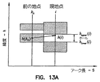
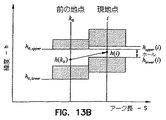
現ステップでは、増分遷移コストが計算される。遷移コストは、燃料、時間、上空通過料金のコストと、そのステップで危険を通過する場合の危険コストとを含む。垂直遷移が天候を通過するかどうかを決定するために、2点間の危険セルの間にホールが存在するかどうかが決定される。2つの危険がある構成についてのホール計算の一例を図13Aおよび図13Bに示す。図13Aに、荒天のノードから荒天でないノードへの遷移を示す。図13Bに、経路が荒天を横切らない、荒天でない2点間の遷移を示す。
【0070】
以下の論理により、ホールが存在するか否かおよびホールサイズが決定される。まず、以前の高度の周囲の空間に対する高度の上界および下界がグリッドポイントで可能され、現地点の周囲の空間に対する上界および下界も計算される。次いで、以下が計算される。
【0071】
a)荒天での以前の高度(図13A参照)
i=遷移する高度(i=1,jvlevels)
h(k0)<hupper(i)かつh(k0)>hlower(i)である場合、ホールが存在する
holesize=hupper(i)−hlower(i)
b)荒天でない以前の高度(図13B参照)
if(hupper0<hupper(i))then
holehigh=hupper0
else
holehigh=hupper(i)
endif
if(hlower0<hlower(i))then
holelow=hlower0
else
holelow=hlower(i)
endif
holesize=hhigh−hlow
c)ホールの存在
holesize>1000ft.(304.8メートル)である場合、ホールが存在する
ホールが存在する場合、遷移は荒天を通過しない。その場合遷移コストは、
ΔC=(Δfuel+CIΔt)hfree ;非制限巡航へ移行し且つ危険に遭遇しない場合
ΔC=(Δfuel+CIΔt)hfree+Δhazard ; 非制限巡航へ移行し且つ危険に遭遇する場合
ΔC=(Δfuel+CIΔt)hspecified ; 制限巡航へ移行し且つ危険に遭遇しない場合
ΔC=(Δfuel+CIΔt)hspecified +Δhazard ; 制限巡航へ移行し且つ危険に遭遇する場合
最後に、合計累積コストをコスト再帰公式
C(ip,jp,kp)=C(i0,j0,k0)+ΔC
から計算する。
【0072】
先に地点に達した場合、以前のコストを現コストと比較する。合計現コストがノードに格納された合計コストよりも低い場合、その新しいコスト、進入方向、高度、重量、時間、hupper、hlowerがグリッド位置ip,jp,kpに格納される。遷移高度に対応する高度グリッドポイント位置(kp)は、
kp=整数(h(kv)/Δh+.5)
上式で、
kv=垂直遷移数(図12の例示ではkv=1,3)
各グリッド点に格納される量は、
C(ip,jp,kp)=C(i0,j0,k0)+ΔC
hor_entry(ip,jp,kp)=entry_direction
vert_entrydirection(ip,jp,kp)=kp−k0
weight(ip,jp,kp)=weight(i0,j0,k0)−Δw
time(ip,jp,kp)=time(i0,j0,k0)−Δt
h(ip,jp,kp)=h(kv)
hupper(ip,jp,kp)=hupper(kv)
hlower(ip,jp,kp)=hlower(kv)
高度グリッドがいくつかの離散的レベルに量子化される場合であっても、実際の高度(例えば条件なし巡航高度)が離散的位置に格納され、取り出すことができるので、それがより正確にわかることに留意されたい。
【0073】
複数のRTA(所要到着時間)関数が、軌跡に沿う複数の地点での到着時間に適合する軌跡を計画する。複数のRTAの手法は、順次式の手法である。まず、第1の都市での到着時間に適合する軌跡を計算する。次に、後続の各都市または位置への到着時間に適合する軌跡を決定する。各地点でのRTAが、現地点と次の地点の間の軌跡反復によって達成される。最初の反復時に、コスト指標を選択する。第1軌跡を計算した後、到着時間誤差を計算し、コスト指標を到着時間誤差と共に変更し、軌跡を再計算する。
【0074】
CIi+1=CIi+KΔTi
次の地点での所望の到着時間を達成した後、後続の各地点についてプロセスを反復する。次のシーケンスの開始に関する重量および時間の初期条件は、先のプロセスの終了時の重量および時間である。順次データを合計し、燃料使用料および平均速度を決定する。
【0075】
RTAウィンドウ関数は、最も早い可能な到着時間および最も遅い可能な到着時間を決定する。最も早い到着時間は、CI=CImaxに設定することによって求められる。最も遅い到着時間は、CIを最大航続時間値(CImin)に設定することによって求められる。この設定でフライトを計算し、次いで、残りの燃料が予備レベルに達するまでフライトの延長をシミュレーションする。この延長巡航により、待機経路または別のルート延長操作で使用される燃料および時間が推定される。
【0076】
結論
このルートソルバは、航空便の運航管理者またはパイロットがルートを計画する助けとなる。一般には、フライトを計画するとき、パイロットまたは運航管理者は、燃料、時間、および上空通過料金を最小限に抑え、厳しい天候(対流、乱気流、および着氷)、特別用途空域、火山灰、環境的および政治的に微妙な領域などの危険領域を回避することを望む。ルート決定問題を図14に示す。燃料/時間性能を最良にするために、最良のルートは、風プロファイルをたどることができ、危険領域の周囲、上、または下を飛行することができる。
【0077】
以下の様々な目標のうち1つまたは複数を満たすルートが発見される。
・燃料を最小限に抑える
・時間または時間ウィンドウを満たし、またはフライト時間を最小限に抑える
・厳しい天候の領域を回避する
・特別用途空域、火山灰、環境的に微妙な領域などの他の危険領域を回避する
・政治的に微妙な領域を回避する
・非常時にフライトを最も近い空港または望ましい空港にルート変更する
コスト関数に危険コストを含めることにより、危険範囲が探索エリア全体にわたる場合であっても解が保証される。起点から開始し、目的地まで進むことにより、危険位置を時間的に前方に射影することができ、より良好な解が得られる。
【図面の簡単な説明】
【0078】
【図1】ルートオプティマイザのブロック図である。
【図2】図1のルートオプティマイザに関するユーザインターフェースのコンピュータスクリーンショットである。
【図3A】頂部高度および底部高度を有する多角形によって表される危険な天候の3次元表現を示すプロットである。
【図3B】図3Aの多角形の頂部高度および底部高度を示すプロットである。
【図4】針路および方向を有する天候を示すプロットである。
【図5】多角形境界で定義された危険領域を示すNCARグレーデッドデータのコンピュータスクリーンショットである。
【図6A】危険エリア内の水平ステップの長さを決定する方法の3次元グラフ表現である。
【図6B】危険エリア内の水平ステップの長さを決定する方法の2次元グラフ表現である。
【図7】入口点および出口点を有する国境を超えるフライト経路の表現である。
【図8】大圏平面上のステップ距離の射影である。
【図9A】軌跡反復に関する収束領域のグラフ表現である。
【図9B】軌跡反復に関する収束領域のグラフ表現である。
【図10A】ルートオプティマイザによって使用されるノードの3次元グリッドの表現である。
【図10B】所与のノードから調査すべき横方向ステップのグラフ表現である。
【図10C】所与のノードから調査すべき垂直ステップのグラフ表現である。
【図10D】所与のノードから調査すべき合成横方向/垂直ステップのグラフ表現である。
【図11】横方向経路を決定するのに使用される反復的プロセスのグラフ表現である。
【図12】荒天を通る様々なタイプの遷移のグラフ表現である。
【図13A】荒天の高度からの遷移のグラフ表現である。
【図13B】荒天でない高度からの遷移のグラフ表現である。
【図14】危険、国上空通過料金、およびウインドフィールドを示すルート計画に対する幾何形状の3次元表現である。【Technical field】
[0001]
The present invention relates to a route planner, and more particularly to a four-dimensional route planner.
[Background]
[0002]
Cross-reference to related applications
This application is related to US Patent Application No. 223,846 “Multi-Dimensional Route Optimizer” filed December 31, 1998, assigned to the assignee of the present application, and at least a recursive algorithm. The teachings of lateral route optimization using are incorporated herein by reference.
[0003]
Copyright notice / permission
Part of the disclosure of this patent document includes material that is subject to copyright protection. The copyright owner has no objection to how many copies of this patent disclosure are found in the US Patent and Trademark Office patent file or record, but otherwise all rights are reserved. Retain anything. The following displays apply to the software and data described below and in the drawings attached hereto. Copyright (C) 2001, Honeywell Inc. , All rights reserved.
[0004]
For safety and efficiency, aircraft routing generally follows a given airway or great circle course. A given airway is often registered using a navigation aid ground facility. In some cases, the airway bypasses the geographic area. On the other hand, the greater route guarantees a shorter flight distance.
[0005]
Weather affects both the efficiency and safety of a particular flight. Aircraft efficiency increases with good wind. With proper tailwind, ground speed will increase and fuel consumption will decrease. Reduced fuel consumption often means that additional payloads can be generated that generate revenue. An increase in ground speed means that the flight time is shortened, resulting in savings in operating costs.
[0006]
Similarly, dangerous weather can incur various costs associated with aircraft operations. Such costs range from low cost, which makes passengers uncomfortable, to high cost, structural damage, and the loss of aircraft and human life. Aircraft pilots usually travel long distances to avoid dangerous weather.
[0007]
In addition, certain geographic and political areas are covered by restricted airspace. Such areas and severe weather are called hazardous areas. Flights in certain areas are preferably kept to a minimum as they can be subject to expensive air travel charges.
[0008]
This is important because achieving the desired arrival time allows the pilot to schedule flights more accurately and accept higher operational efficiencies. An aircraft operating on a given airway or great circle course may be forced to make costly adjustments to airspeed to meet scheduling requirements.
DISCLOSURE OF THE INVENTION
[Problems to be solved by the invention]
[0009]
A typical flight path router plots the flight path in the lateral direction to avoid danger, utilize the wind, and leave the vertical portion of the path in the standard cruise profile. Furthermore, the flight path router takes into account the altitude of the airflow. Such route determination typically does not take into account the vertical dimension of the danger area and the nature of the danger area over time, and therefore the resulting route is less desirable. There is a need for a system that addresses these shortcomings.
[Means for Solving the Problems]
[0010]
The route planner uses a dynamic programming (DP) recursive algorithm to determine the lateral / vertical path. The cost function includes a fuel cost, a time cost, and a risk cost, and the flying charge is minimized. The danger area is described by a polygon having a top elevation and a bottom elevation. In one embodiment, the danger area is given a course and speed and therefore moves with time.
[0011]
The route planner determines the course by moving from node to node in the grid of nodes established for the origin and destination. The local step cost is added to the accumulated cost for the next node. The transition step to the node with the lowest accumulated cost for the node is retained, and as a result, the lowest cost route from the origin to the destination is found. When faced with a danger area, movement to a new node is explored in multiple vertical paths in an attempt to find a low-cost transition that does not pass through the danger. If this step passes risk, an incremental risk cost is added to the accumulated cost. In another embodiment, the route planner attempts to find a route that satisfies the required arrival time window. The route can be divided into a plurality of start points and end points with a desired arrival time for each end point.
BEST MODE FOR CARRYING OUT THE INVENTION
[0012]
In the following description, reference is made to the accompanying drawings that form a part hereof, and in which are shown by way of illustration specific embodiments in which the invention may be practiced. These embodiments are described in sufficient detail to enable those skilled in the art to practice the invention. It should be understood that other embodiments may be used and structural, logical, and electrical changes may be made without departing from the scope of the present invention. The following description is, therefore, not to be taken in a limiting sense, and the scope of the present invention is defined by the appended claims.
[0013]
Software for the system is stored on a computer readable medium. In one embodiment, the software is stored on secondary storage, such as a disk drive, and loaded into the computer's main memory and cache as needed. Software is written in the form of modules that typically provide a single function or a subset of related functions. However, in various embodiments, the software includes a single module or multiple modules, and there is no requirement to group functions. In another embodiment, hardware and / or firmware is used to implement the present invention. The software can implement the function or simply facilitate the implementation of the function by a human by providing a menu driven interface or other means of providing information to a database storage system.
[0014]
Route optimization for vehicles such as aircraft is provided by the route optimizer of the present invention. Route optimization consists of a lateral path and a vertical path. The lateral path is assigned to the assignee of the present application, and at least U.S. patent application filed on Dec. 31, 1998, whose teachings of lateral route optimization using a recursive algorithm are incorporated herein by reference. 09 / 223,846 "Multi-Dimensional Route Optimizer" is largely determined accordingly.
[0015]
The vertical path is determined by using an adaptive algorithm that takes into account the three-dimensional danger area. The three-dimensional danger area is represented as a polygon that has a height and can also have a velocity component and a direction component.
[0016]
A definition section is given first, followed by a high-level overview of the route optimizer. Next, a representation of the danger area is defined, followed by further details on how to calculate the vertical and horizontal paths taking such danger areas into account.
[0017]
Definition
CL Lift coefficient
Cd Drag coefficient
CI cost index
CF cost function
D Drag
Dgc Greater sphere distance
FFR Fuel flow rate
h Altitude
h (k0Altitude from previous grid point
hupper
hlower
L Lift
M Mach number
MTO maximum takeoff weight
mf Fuel mass
sos sound speed
V Ground speed
Va Airspeed
Vw wind speed
W weight
Wf Fuel weight
R Charges for overpass
RTA required arrival time
Sa Aerodynamic reference area
S Moved arc long distance
T The unit rate for air travel charges
ΔS Step in long arc distance traveled
θ Longitude
φ Latitude
pi throttle
Ψ Great circle direction for overpass charges
[0018]
A route solver, indicated generally at 110 in FIG. 1, minimizes the combined cost function consisting of fuel costs, time costs, danger costs, and overpass charges, and reduces the required arrival time (RTA). Compute a 4D (3 locations and time) route to fill. In one embodiment,
[0019]
The processing elements include pilot /
[0020]
1.1 Pilot / Operation Manager Interface
An operator, pilot, or flight manager can interact with the route solver via the
[0021]
The operator can enter a city pair, risk, risk weight, and required arrival time. After the calculation, the horizontal route is displayed on the word map. A vertical route with a number of dangers is also displayed. A window can be selected that includes fuel hourly average speed and cost performance results. The operator can change the route by changing the risk weighting.
[0022]
1.2 Route determination method
The route is calculated using a dynamic programming (DP) method. In DP, a search is performed on the grid to find a path that minimizes the cost function. The cost function includes fuel cost, time cost, danger cost, and overpass cost. The total cost is the sum of the incremental costs.
ΔCost = ΔCostfuel+ ΔCosttime+ ChΔcosthazard+ Δcostoverlight
Hereinafter, each term in the cost function will be described.
[0023]
Danger cost: Danger is severe weather, volcanic ash, special purpose airspace, and politically sensitive areas. All of the risk costs can be determined as well. The danger expression is three-dimensional as shown in FIG. 3A showing a perspective view of the danger expression. FIG. 3B shows the danger expression altitude as having a top altitude and a bottom altitude. Some hazardous areas have a bottom altitude at the ground surface and a top altitude that exceeds the range of the aircraft. As shown in FIG. 4, the danger polygon starts at a certain reference time and moves with a fixed course and speed.
[0024]
Weather costs represent the risk of passing through severe weather areas. Weather hazards are classified as convection, turbulence, and icing. As shown in FIG. 5, the weather region is represented as a polygon surrounding the severe weather region. The polygon is shown as a double line surrounding a white square that represents the actual radar echo in dangerous weather. In one embodiment, the polygon has a plurality of vertices and is selected by the system operator or automatically generated from weather information.
[0025]
The danger database consists of polygon vertices, speeds, courses, top and bottom areas, and associated danger costs, which can be entered by the user in FIG.
The risk cost depends on the risk cost of the particular cell and the distance traveled during the step. A method for determining the length of the horizontal step in danger is shown in FIGS. 6A and 6B.
[0026]
To calculate the distance, assume that the region is a convex polygon with points designated in counterclockwise order. The steps are as follows: For each polygon segment, determine d.
v = pi× pi + 1
d = v · p
For each polygon segment, Pnext, PcurrentD corresponding tonext, DcurrentDefine
[0027]
dnext, Dcurrent<If 0 => Ends because the segment is outside
Instead, dnext<0, dcurrentIf> 0 => PnextClip
Instead, dnext> 0, dcurrent<If 0 => PcurrentClip
Where pnextThe clip function for is
[0028]
[Expression 1]
After processing the root segment for each polygon, the intersection of the polygon and the original root segment (Δs1)
[0030]
[Expression 2]
![]()
The danger cost is the distance in danger (Δs1) And the step distance.
[0032]
[Equation 3]
![]()
Fuel and time costs: Fuel and time costs are determined from the optimal cruise performance conditions of the aircraft. There are two different types of cruise performance. If there is no danger area, cruise altitude and speed are freely chosen to optimize the cruise cost function. If a danger area exists, the cruise altitude, for example, the top or bottom altitude of the danger area can be specified. Thus, there are two possible cruise solution types. 1) Unconditional cruise: Altitude is freely selected. 2) Conditional altitude cruise: Altitude is specified.
[0034]
When cruising, the cost integral (C) is minimized.
[0035]
[Expression 4]
CI is the ratio of the cost of time (in monetary units) to the cost of fuel (in monetary units). By increasing the cost index (CI), more emphasis can be placed on time. For small arc length steps ΔS, the fuel, time, and cost increments are
[0037]
[Equation 5]
Traditionally, fuel / time costs are combined as a single cost function (CF).
CF = (FFR + CI) / V
In this case, ΔCost = CFΔs
Fuel / time cruise performance solutions are pre-calculated by the aircraft manufacturer and then provided to the user in a table as a function of weight, cost index, wind speed, and altitude parameters. These two types of cruise models are
Cruise without altitude restriction: No altitude specified
[0039]
[Formula 6]
Altitude restricted cruise: Altitude specified
[0041]
[Expression 7]
When the aircraft is in free cruise, an unrestricted solution is used. When the aircraft is forced to fly at an altitude above or below the free cruise altitude, an altitude limited solution is used. The above model is typical for use in flight management systems.
[0043]
Flyover charges: In general, flyover charges depend on weight, distance traveled, and rate (cost per distance). Flyover charges are calculated separately for each country. Some fee types are fixed rate, a function of weight, a function of weight, distance, and rate, the following are some formulas used.
[0044]
Official # 1 (Euro Control countries and other countries)
[0045]
[Equation 8]
Where
R = rate
T = unit rate
Dge= Greater sphere distance
W = Maximum take-off weight in metric tons (MTOW)
Official # 2 (ASECNA countries)
R = unit rate x coefficient (determined from Table 1)
[0047]
[Table 1]
The distance is the actual distance traveled, or the great circle distance between the entry point and the destination country's airport, ie, the exit point, or the great circle between the origin country airport and the country's exit point. Distance is enough. The difference between the distance moved and the great circle distance is shown in FIG. The border is a political boundary, an ATC flight information area (FIR), or a combination of both.
[0049]
To calculate the great circle distance, a projection of the step distance (ΔS) onto the great circle plane defined by the entry and departure points of the country is used (see FIG. 8). Entrance point (Re) And starting point (Rd) Is normal to the plane containing
[0050]
[Equation 9]
Each component of n in the earth center coordinate system rotates to the current coordinate system with the x-axis pointing outward from the earth.
nR= T (φ, θ) ne
Next, the local point R, (n1 -) (N1 -Is n1Over the head-The projection of n onto the local vertical line at (1 -Is obtained by setting the vertical component of to zero.
[0052]
[Expression 10]
Then the projection of ΔS is
[0054]
[Expression 11]
![]()
When the distance factor is the great circle distance, iterative trajectory is required to calculate the overpass cost. During the first iteration, during execution, the arc length is used for the distance, not the great circle distance. Again at the first iteration, the country entry and departure points are calculated at the end of the run being retraced. In subsequent iterations, the country entry and departure points from the previous pass are used in the great circle distance calculation.
[0056]
To help convergence of the iterative process, after the first iteration, the area of the search that determines the route is limited to the region around the previous route, as shown in FIGS. 9A and 9B.
The following formula is used to determine if a point is in the region. The distance between the entry point and the start point in earth coordinates is
ΔRpx= Rdx-Rex
ΔRpy= Rdy-Rey
ΔRpz= Rdz-Rez
The relative distance in the local vertical coordinate system is
ΔRx= CosφcosθΔRex+ CosφsinθΔRey+ SinφΔRez
ΔRy= SinθΔRex+ CosθΔRey
ΔRz= -SinφcosθΔRex-CosφsinθΔRey+ CosφΔRez
The angle between the local vertical coordinate system and the coordinate system with the y-axis along the great circle is
[0057]
[Expression 12]
The search area is defined by:
ymax= CosφΔRy+ SinΨΔRz+ 2k
zmax= 500nm
k = 100 nm
The component of the current relative position measured from the entry point in the Earth coordinate system is
ΔRpx= Rpx-Rex
ΔRpy= Rpy-Rey
ΔRpz= Rpz-Rez
Current relative position in the local vertical coordinate system (ΔRp) Ingredients
ΔRpx= CosφcosθΔRpex+ CosφsinθΔRpay+ SinφΔRpez
ΔRpy= SinθΔRpex+ CosθΔRpay
ΔRpz= -SinφcosθΔRpex-CosφsinθΔRpay+ CosφΔRpez
The current relative position in the post-rotation coordinate system is
y = cosΨΔRpy+ SinΨΔRpz
z = −sinΨΔRpy+ CosΨΔRpz
The z boundary point at y is
[0059]
[Formula 13]
The following equation is used to determine if the point (y, z) is within the search region.
if (z ≦ z1And z ≧ z2) Within the then area,
sf = 1.05Δsp/ Δs; if (sf ≧ 1) sf = 1; sf = scale factor
else outside the region, then
sf = 10
end
The distance used in the calculation of the air passage fee is the scale factor multiplied by the step distance.
d = sfΔS
Therefore, there is a large penalty for being outside the area.
[0061]
1.2 Four-dimensional (4D) dynamic programming route solver
In the following, a four-dimensional (latitude, longitude, altitude and time) route solver will be described. First, a three-dimensional dynamic programming route solver will be described, and then a multi-point required arrival time (RTA) function will be described.
[0062]
In the dynamic programming (DP) method, a 3D grid search is performed to minimize the cost function. The DP solution formula consists of a set of state transition formulas and an induction formula to minimize the cost function. The general form of DP type is
State transition
θk + 1= Θk+ Δθ
φk + 1= Φk+ Δφ
hk + 1= Hk+ Δh
Inductive cost
[0063]
[Expression 14]
Δφ, Δθ, Δh = management
On the horizontal axis, a fixed pattern search is used, while on the vertical axis, an adaptive search is used to reduce the number of calculations.
[0065]
The calculation starts at the starting point and ends at the destination. This makes it possible to propagate the dangerous position forward in time using the course and speed. Since the state condition including the weight is known, the route during the flight can be recalculated by starting at the starting point.
[0066]
Transition types between 3D grids and grid points are shown in FIGS. 10A, 10B, 10C, and 10D. The starting point and the destination point are included in the three-dimensional grid of FIG. 10A. In FIG. 10B, 11 potential lateral steps are shown. In another embodiment, fewer or more potential steps can be searched, even in directions away from the destination. As shown in the figure, the distance of each step depends on the moving grid point. In FIG. 10C, five different vertical steps from the node are shown. You can also search for a smaller number. FIG. 10D is a graphical representation of a combination of horizontal steps, ie, horizontal and vertical steps.
[0067]
An illustration of the DP process is shown in FIGS. In FIG. 11, the first and second stages of the process on the horizontal axis are shown. In this example, there are nine exit heading directions for each heading heading direction. As shown in FIG. 12, for each horizontal transition, several vertical transitions are examined. Like horizontal transitions, vertical transitions are not predetermined and depend on the location and the number of dangerous cells. That is, the vertical search adapts itself to its previous state. This adaptive search technique reduces the number of calculations that must be performed.
[0068]
The vertical transition height is different for different configurations of overlapping risks. Altitude assignment depends on the location of unconditional cruise altitudes for multiple risk cells. First, find the location of the unconditioned cruise altitude, and then assign other transition altitudes to the top and bottom of the danger cell, depending on the location. In this example shown in FIG. 12, an unconditioned cruise altitude is between the weather cells. In this case, the cruise altitude is assigned to altitude h (1), the top of cell (1) is assigned to altitude h (2), and the bottom of cell (2) is assigned to h (3).
[0069]
In the current step, an incremental transition cost is calculated. The transition cost includes the cost of fuel, time, and air charge, and the danger cost when passing danger in that step. To determine whether a vertical transition passes through the weather, it is determined whether there is a hole between the danger cells between the two points. An example of hole calculation for two risky configurations is shown in FIGS. 13A and 13B. FIG. 13A shows a transition from a stormy node to a node that is not stormy. FIG. 13B shows a transition between two points that are not stormy and the route does not cross stormy weather.
[0070]
The following logic determines whether a hole exists and the hole size. First, the upper and lower bounds for the altitude surrounding the previous altitude space are enabled at the grid points, and the upper and lower bounds for the space surrounding the local point are also calculated. The following is then calculated:
[0071]
a) Previous altitude in stormy weather (see Figure 13A)
i = altitude for transition (i = 1, jvlevels)
h (k0<Hupper(I) and h (k0)> HlowerIf (i), there is a hole
holesize= Hupper(I) -hlower(I)
b) Previous altitude not in stormy weather (see Fig. 13B)
if (hupper0<Hupper(I)) then
holehigh= Hupper0
else
holehigh= Hupper(I)
endif
if (hlower0<Hlower(I)) then
holelow= Hlower0
else
holelow= Hlower(I)
endif
holesize= Hhigh-Hlow
c) existence of holes
holesize> 1000 ft. If it is (304.8 meters), there is a hole
If there is a hole, the transition does not pass through stormy weather. In that case, the transition cost is
ΔC = (Δfuel + CIΔt) hfree When shifting to unrestricted cruise and not encountering danger
ΔC = (Δfuel + CIΔt) hfree+ Δhazard ; If you are going to unrestricted cruise and encounter danger
ΔC = (Δfuel + CIΔt) hspecified ; If you enter restricted cruise and do not encounter danger
ΔC = (Δfuel + CIΔt) hspecified + Δhazard ; When entering a restricted cruise and encountering danger
Finally, the total recurring cost is the cost recursion formula
C (ip, Jp, Kp) = C (i0, J0, K0) + ΔC
Calculate from
[0072]
If the point is reached first, compare the previous cost with the current cost. If the total current cost is lower than the total cost stored in the node, the new cost, direction, altitude, weight, time, hupper, HlowerIs the grid position ip, Jp, KpStored in Altitude grid point position (kp)
kp= Integer (h (kv) / Δh +. 5)
Where
kv= Number of vertical transitions (k in the example of FIG.v= 1, 3)
The amount stored at each grid point is
C (ip, Jp, Kp) = C (i0, J0, K0) + ΔC
hor_entry (ip, Jp, Kp) = Entry_direction
vert_entrydirection(Ip, Jp, Kp) = Kp-K0
weight (ip, Jp, Kp) = Weight (i0, J0, K0-Δw
time (ip, Jp, Kp) = Time (i0, J0, K0) -Δt
h (ip, Jp, Kp) = H (kv)
hupper(Ip, Jp, Kp) = Hupper(Kv)
hlower(Ip, Jp, Kp) = Hlower(Kv)
Even if the altitude grid is quantized to several discrete levels, the actual altitude (eg unconditional cruising altitude) can be stored and retrieved at discrete locations so that it is more accurately known Please note that.
[0073]
A plurality of RTA (Required Arrival Time) functions plan a trajectory that matches the arrival time at a plurality of points along the trajectory. The plurality of RTA techniques are sequential techniques. First, a trajectory that matches the arrival time in the first city is calculated. Next, a trajectory that matches the time of arrival at each subsequent city or location is determined. RTA at each point is achieved by trajectory iteration between the local point and the next point. During the first iteration, select a cost metric. After calculating the first trajectory, the arrival time error is calculated, the cost index is changed together with the arrival time error, and the trajectory is recalculated.
[0074]
CIi + 1= CIi+ KΔTi
After achieving the desired arrival time at the next point, the process is repeated for each subsequent point. The initial weight and time conditions for the start of the next sequence are the weight and time at the end of the previous process. Sequential data are summed to determine fuel usage and average speed.
[0075]
The RTA window function determines the earliest possible arrival time and the latest possible arrival time. The earliest arrival time is CI = CImaxIs determined by setting to. The latest arrival time is the CI value of the maximum cruising time value (CImin). The flight is calculated at this setting and then the flight extension is simulated until the remaining fuel reaches the reserve level. This extended cruise estimates the fuel and time used in the standby route or another route extension operation.
[0076]
Conclusion
This route solver helps airline flight managers or pilots plan routes. In general, when planning a flight, the pilot or flight manager will minimize fuel, time, and air travel charges, severe weather (convection, turbulence, and icing), special-use airspace, volcanic ash, environmental And want to avoid dangerous areas such as politically sensitive areas. The route determination problem is shown in FIG. For best fuel / time performance, the best route can follow the wind profile and can fly around, above or below the danger zone.
[0077]
A route is found that meets one or more of the following various goals.
・ Minimize fuel
Meet time or time window or minimize flight time
・ Avoid severe weather areas
Avoid other hazardous areas such as special purpose airspace, volcanic ash, environmentally sensitive areas
・ Avoid politically sensitive areas
Reroute flights to the nearest or preferred airport in case of emergency
By including the risk cost in the cost function, the solution is guaranteed even if the risk range covers the entire search area. By starting from the starting point and proceeding to the destination, the dangerous position can be projected forward in time, and a better solution can be obtained.
[Brief description of the drawings]
[0078]
FIG. 1 is a block diagram of a route optimizer.
FIG. 2 is a computer screen shot of a user interface for the route optimizer of FIG.
FIG. 3A is a plot showing a three-dimensional representation of dangerous weather represented by a polygon having a top elevation and a bottom elevation.
FIG. 3B is a plot showing the top and bottom elevations of the polygon of FIG. 3A.
FIG. 4 is a plot showing weather with course and direction.
FIG. 5 is a computer screen shot of NCAR graded data showing a dangerous area defined by a polygon boundary.
FIG. 6A is a three-dimensional graph representation of a method for determining the length of horizontal steps in a danger area.
FIG. 6B is a two-dimensional graph representation of a method for determining the length of a horizontal step in a danger area.
FIG. 7 is a representation of a flight path across a border with an entry point and an exit point.
FIG. 8 is a projection of a step distance on the great circle plane.
FIG. 9A is a graphical representation of a convergence region for trajectory repetition.
FIG. 9B is a graphical representation of the convergence region for trajectory iteration.
FIG. 10A is a representation of a three-dimensional grid of nodes used by the root optimizer.
FIG. 10B is a graphical representation of a lateral step to be examined from a given node.
FIG. 10C is a graphical representation of vertical steps to be examined from a given node.
FIG. 10D is a graphical representation of a composite lateral / vertical step to be examined from a given node.
FIG. 11 is a graphical representation of an iterative process used to determine a lateral path.
FIG. 12 is a graphical representation of various types of transitions through stormy weather.
FIG. 13A is a graphical representation of transitions from stormy altitudes.
FIG. 13B is a graphical representation of transitions from altitudes that are not stormy.
FIG. 14 is a three-dimensional representation of the geometry for a route plan showing danger, over-the-counter charges, and windfields.
Claims (26)
危険エリアの3次元表現の関数に応じて高度を変更するステップと、
前記ノードから別のセグメントを反復的に決定し、前記起点と前記目的地との間の複数のセグメント経路を作成するステップと、
最小コストを有する、前記起点と目的地との間のセグメント経路を決定するステップと、
を含む起点と目的地の間のルートを決定する方法。Determining a plurality of feasible segments starting from an origin and ending at the end of each feasible segment from the origin; and
Changing the altitude according to the function of the three-dimensional representation of the dangerous area;
Repetitively determining another segment from the node and creating a plurality of segment paths between the origin and the destination;
Determining a segment path between the origin and destination having a minimum cost;
To determine the route between the origin and destination, including
前記起点ノードから隔てて位置する目的地ノードを受け取るステップと、
前記起点ノード、前記目的地ノード、および複数のルートノードを含むグリッドを作成するステップと、
前記目的地ノードおよび前記複数のルートノードへ遷移するコストを決定するステップと、
3次元危険エリアに応じて前記高度を変更するステップと、
前記複数のルートノードからノードのサブセットを選択するステップと、を含み、
前記各ノードは複数の高度を有し、前記ノードのサブセットは、前記起点ノードから前記目的地ノードへの遷移の最小合計コストを有する、
ルートを決定する方法。Receiving an origin node;
Receiving a destination node located away from the origin node;
Creating a grid including the origin node, the destination node, and a plurality of root nodes;
Determining a cost to transition to the destination node and the plurality of root nodes;
Changing the altitude according to a three-dimensional danger area;
Selecting a subset of nodes from the plurality of root nodes;
Each node has a plurality of altitudes, and the subset of nodes has a minimum total cost of transition from the origin node to the destination node;
How to determine the route.
前記起点ノードの前記グローバル座標を、前記起点が赤道上となる座標系に変換するステップと、
前記目的地ノードの前記グローバル座標を、前記目的地が赤道上となる座標系に変換するステップとをさらに含む、請求項7に記載の方法。Receiving the origin node includes receiving an origin node expressed in global coordinates, and receiving the destination node includes receiving a destination node expressed in global coordinates;
Transforming the global coordinates of the origin node into a coordinate system in which the origin is on the equator;
The method of claim 7, further comprising transforming the global coordinates of the destination node into a coordinate system in which the destination is on the equator.
前記起点ノードから離れた目的地ノードを受け取るステップと、
前記起点ノードからそれぞれ始まり、前記目的地ノードで終了し、1つまたは複数の中間ノードを横切る複数の経路を定義するステップと、
横方向次元および垂直次元で定義される危険に応答して、様々な高度で別の中間ノードを定義するステップと、
様々な高度で定義される前記中間ノードを使用する別の経路定義するステップと、
前記複数の経路それぞれを横切ることに関連するコストを決定するステップと、
所定のコスト関数を満たす経路を選択するステップと、
を含む横方向ルートおよび垂直ルートを選択する方法。Receiving an origin node; and
Receiving a destination node away from the origin node;
Defining a plurality of paths, each starting from the origin node, ending at the destination node, and traversing one or more intermediate nodes;
Defining different intermediate nodes at various altitudes in response to hazards defined in the lateral and vertical dimensions;
Defining another route using the intermediate node defined at various altitudes;
Determining a cost associated with traversing each of the plurality of paths;
Selecting a path that satisfies a predetermined cost function;
To select horizontal and vertical routes including
前記起点および目的地を包含する3次元グリッドで複数のノードを確立するステップと、
前記起点ノードから開始し、前記ビークルを前記起点ノードに近接する複数のノードに移動するコストを決定するステップと、
前記複数のノードから、別の複数のノードに移動する遷移コストを前記変数の関数として求めるステップと、
3次元危険エリアに応答して高度を変更するステップと、
前記ノードからの別のコストを反復的に求め、前記起点と前記目的地との間の複数のルートを作成するステップと、
を含む方法。A method for determining a route between an origin and a destination with respect to a vehicle taking into account variables as the vehicle moves along the route,
Establishing a plurality of nodes in a three-dimensional grid encompassing the origin and destination;
Determining a cost of starting from the origin node and moving the vehicle to a plurality of nodes proximate to the origin node;
Determining a transition cost for moving from the plurality of nodes to another node as a function of the variable;
Changing the altitude in response to the 3D danger area;
Recursively determining another cost from the node and creating a plurality of routes between the origin and the destination;
Including methods.
危険エリアの3次元表現に応じて高度を変更する手段と、
前記ノードから別のセグメントを反復的に求め、前記起点と前記目的地との間の複数のセグメント経路を作成する手段と、
最小コストを有する、前記起点と目的地との間のセグメント経路を決定する手段と、
を含む起点と目的地の間のルートを決定するシステム。Means for determining a plurality of feasible segments starting from an origin and ending at the end of each feasible segment;
Means for changing the altitude according to the three-dimensional representation of the danger area;
Means for iteratively determining another segment from the node and creating a plurality of segment paths between the origin and the destination;
Means for determining a segment path between said origin and destination having a minimum cost;
A system that determines the route between the origin and destination, including
適応アルゴリズムを実装して、頂部高度および底部高度を有する水平多角形によって表される危険エリアに基づいて調節される垂直経路を決定するモジュールと、
を備えるルートプランナ。A module that implements a recursive algorithm to determine the horizontal path;
A module that implements an adaptive algorithm to determine a vertical path that is adjusted based on a danger area represented by a horizontal polygon having a top elevation and a bottom elevation;
Route planner with
Applications Claiming Priority (2)
| Application Number | Priority Date | Filing Date | Title |
|---|---|---|---|
| US09/957,416 US20030093219A1 (en) | 2001-09-20 | 2001-09-20 | Four-dimensional route planner |
| PCT/US2002/029474 WO2003025507A2 (en) | 2001-09-20 | 2002-09-17 | Four-dimensional route planner |
Publications (2)
| Publication Number | Publication Date |
|---|---|
| JP2005504274A true JP2005504274A (en) | 2005-02-10 |
| JP2005504274A5 JP2005504274A5 (en) | 2006-01-05 |
Family
ID=25499537
Family Applications (1)
| Application Number | Title | Priority Date | Filing Date |
|---|---|---|---|
| JP2003529091A Pending JP2005504274A (en) | 2001-09-20 | 2002-09-17 | 4D route planner |
Country Status (9)
| Country | Link |
|---|---|
| US (1) | US20030093219A1 (en) |
| EP (1) | EP1427991A2 (en) |
| JP (1) | JP2005504274A (en) |
| KR (1) | KR20040033068A (en) |
| CA (1) | CA2461134A1 (en) |
| IL (1) | IL160986A0 (en) |
| NO (1) | NO20041526L (en) |
| NZ (1) | NZ532117A (en) |
| WO (1) | WO2003025507A2 (en) |
Cited By (9)
| Publication number | Priority date | Publication date | Assignee | Title |
|---|---|---|---|---|
| JP2009502651A (en) * | 2005-08-04 | 2009-01-29 | ザ・ボーイング・カンパニー | Automatic fuel supply information tracking and fuel hedging |
| WO2010110079A1 (en) * | 2009-03-25 | 2010-09-30 | 三洋電機株式会社 | Vehicle-mounted electronic device |
| JP2011143774A (en) * | 2010-01-13 | 2011-07-28 | Japan Aerospace Exploration Agency | Turbulence avoidance operation assist device |
| JP2012158322A (en) * | 2011-01-28 | 2012-08-23 | Boeing Co:The | Provision of data for predicting aircraft trajectory |
| JP2014016264A (en) * | 2012-07-10 | 2014-01-30 | Fuji Heavy Ind Ltd | Avoidance route deprivation device, avoidance route deprivation program, and avoidance route deprivation method |
| JP2017181185A (en) * | 2016-03-29 | 2017-10-05 | 株式会社ゼンリンデータコム | Route search device, route search method, and program |
| JPWO2019167161A1 (en) * | 2018-02-28 | 2021-02-25 | 日本電気株式会社 | Area evaluation system, method and program |
| WO2023112245A1 (en) * | 2021-12-16 | 2023-06-22 | 日本電気株式会社 | Management device, management method, and computer-readable storage medium |
| JP7459009B2 (en) | 2021-02-12 | 2024-04-01 | 三菱重工業株式会社 | Route planning device, mobile object, route planning method and program |
Families Citing this family (56)
| Publication number | Priority date | Publication date | Assignee | Title |
|---|---|---|---|---|
| US20040052239A1 (en) | 2002-08-29 | 2004-03-18 | Nesbitt David W. | Automated route determination |
| US7133771B1 (en) * | 2002-08-29 | 2006-11-07 | America Online, Inc. | Automated route determination to avoid a particular maneuver |
| US7321824B1 (en) | 2002-12-30 | 2008-01-22 | Aol Llc | Presenting a travel route using more than one presentation style |
| US7474960B1 (en) | 2002-12-30 | 2009-01-06 | Mapquest, Inc. | Presenting a travel route |
| US7818116B1 (en) | 2002-12-30 | 2010-10-19 | Mapquest, Inc. | Presenting a travel route in a ground-based vehicle |
| DE102004006486A1 (en) * | 2004-02-10 | 2005-08-25 | Köhler, Hans Christian, Dipl.-Math. | Journey control system, especially for application to aircraft, wherein an aircraft is constrained to remain within a defined air corridor, but whereby, with the exception of this constraint, the pilot has full control |
| US7366591B2 (en) * | 2004-06-21 | 2008-04-29 | Honeywell International, Inc. | System and method for vertical flight planning |
| US7966003B2 (en) * | 2004-07-09 | 2011-06-21 | Tegic Communications, Inc. | Disambiguating ambiguous characters |
| US20060161337A1 (en) * | 2005-01-19 | 2006-07-20 | Ping-Chung Ng | Route planning process |
| US20090177339A1 (en) * | 2005-03-03 | 2009-07-09 | Chen Robert H | Optimization and Mechanization of Periodic Flight |
| US7606641B2 (en) | 2005-08-04 | 2009-10-20 | The Boeing Company | Fuel consumption data tracking/collection and aircraft/route optimization |
| EP1770365B1 (en) * | 2005-09-30 | 2011-11-16 | Saab Ab | Method for planning the velocity of a craft along a route |
| US8457892B2 (en) | 2006-03-01 | 2013-06-04 | Toyota Jidosha Kabushiki Kaisha | Own-vehicle-path determining method and own-vehicle-path determining apparatus |
| NZ544381A (en) * | 2006-03-02 | 2008-10-31 | Airways Corp Of New Zealand | System and method for modelling a flight and invoicing the flight providers for services used |
| FR2907952B1 (en) * | 2006-10-26 | 2008-12-19 | Airbus France Sa | METHOD AND DEVICE FOR AIDING THE GUIDANCE OF AN AIRCRAFT ALONG A FLIGHT TRACK. |
| FR2913780B1 (en) * | 2007-03-13 | 2014-07-18 | Airbus France | METHOD AND DEVICE FOR AIDING THE GUIDANCE OF AN AIRCRAFT |
| US7925393B2 (en) * | 2007-08-01 | 2011-04-12 | Arinc Incorporated | Method and apparatus for generating a four-dimensional (4D) flight plan |
| WO2009052404A1 (en) * | 2007-10-17 | 2009-04-23 | Lockheed Martin Corporation | Hybrid heuristic national airspace flight path optimization |
| US20090112645A1 (en) * | 2007-10-25 | 2009-04-30 | Lockheed Martin Corporation | Multi objective national airspace collaborative optimization |
| US9257047B2 (en) * | 2007-12-12 | 2016-02-09 | The Boeing Company | Computation of new aircraft trajectory using time factor |
| US8082102B2 (en) * | 2008-01-14 | 2011-12-20 | The Boeing Company | Computing flight plans for UAVs while routing around obstacles having spatial and temporal dimensions |
| US9513125B2 (en) * | 2008-01-14 | 2016-12-06 | The Boeing Company | Computing route plans for routing around obstacles having spatial and temporal dimensions |
| US20090326894A1 (en) * | 2008-06-27 | 2009-12-31 | Chan Alistair K | Methods of processing wind profile information in sports applications |
| US8864606B2 (en) * | 2008-06-27 | 2014-10-21 | The Invention Science Fund I, Llc | Sports applications for wind profile systems |
| US9733392B2 (en) * | 2008-06-27 | 2017-08-15 | Deep Sciences, LLC | Methods of using environmental conditions in sports applications |
| US20090326887A1 (en) * | 2008-06-27 | 2009-12-31 | Searete Llc, A Limited Liability Corporation Of The State Of Delaware | Wind profile systems for sporting applications |
| WO2010076045A1 (en) * | 2008-12-29 | 2010-07-08 | Tomtom International B.V. | Timed route navigation device |
| US20100211302A1 (en) * | 2008-12-30 | 2010-08-19 | Thales-Raytheon Systems Company Llc | Airspace Deconfliction System |
| DE102009006409B4 (en) * | 2009-01-28 | 2012-10-31 | Eads Deutschland Gmbh | Method and device for route optimization |
| US8386098B2 (en) * | 2009-08-03 | 2013-02-26 | David A. Bailey | Method for a deeper search in a time-limited image satellite planning environment |
| US20130046422A1 (en) * | 2010-04-12 | 2013-02-21 | Flight Focus Pte. Ltd. | Onboard flight planning system |
| US9614624B2 (en) | 2010-05-11 | 2017-04-04 | Deep Science, Llc | Optical power source modulation system |
| US9761148B2 (en) | 2010-08-03 | 2017-09-12 | Honeywell International Inc. | Airborne separation assurance system and required time of arrival function cooperation |
| US8406939B2 (en) * | 2010-09-03 | 2013-03-26 | Honeywell International Inc. | Systems and methods for RTA control of multi-segment flight plans with smooth transitions |
| ITRM20110651A1 (en) * | 2010-12-20 | 2012-06-21 | Selex Sistemi Integrati Spa | METHOD OF QUICK PREDICTION OF THE VERTICAL PROFILE OF THE TRAJECTORY FOR THE MANAGEMENT OF AIR TRAFFIC, AND ITS RELATED ATM SYSTEM. |
| US9086280B2 (en) | 2011-09-07 | 2015-07-21 | Honeywell International Inc. | Aircraft display systems and methods with flight plan deviation symbology |
| US10013236B2 (en) * | 2013-03-06 | 2018-07-03 | The Boeing Company | Real-time adaptive speed scheduler |
| FR3012245B1 (en) * | 2013-10-21 | 2019-05-24 | Thales | METHOD AND DEVICE FOR DETERMINING A PLURALITY OF PERFORMANCE INDICATORS RELATING TO THE FLIGHT OF AN AIRCRAFT, AND ASSOCIATED COMPUTER PROGRAM PRODUCT |
| US20150127302A1 (en) * | 2013-11-07 | 2015-05-07 | The Government Of The United States As Represented By The Secretary Of The Army | Method and apparatus for optimized routing |
| US9620022B2 (en) | 2014-06-10 | 2017-04-11 | Sikorsky Aircraft Corporation | Aircraft motion planning method |
| FR3029652B1 (en) | 2014-12-03 | 2019-12-27 | Thales | METHOD FOR CALCULATING AN AIRPLANE TRAJECTORY SUBJECT TO LATERAL AND VERTICAL CONSTRAINTS |
| EP3936823A1 (en) * | 2014-12-17 | 2022-01-12 | HERE Global B.V. | Providing constraint to a position |
| FR3032271B1 (en) | 2015-01-30 | 2017-01-13 | Thales Sa | METHOD FOR IMPROVING A FLIGHT TRACK OF AN AIRCRAFT BASED ON WEATHER CONDITIONS |
| US10144505B2 (en) * | 2015-05-18 | 2018-12-04 | The Boeing Company | Aircraft flight control using a required time of arrival index |
| US9870711B2 (en) | 2015-06-08 | 2018-01-16 | The Boeing Company | System and method for determining an alternative flight route based on sector geometry |
| EP3211620A1 (en) | 2016-02-26 | 2017-08-30 | The Boeing Company | Method and electronic device for establishing optimized holding patterns for aircraft |
| US10262545B2 (en) | 2016-04-18 | 2019-04-16 | Sikorsky Aircraft Corporation | Optimal flight planner |
| US10459078B2 (en) * | 2016-09-13 | 2019-10-29 | Honeywell International Inc. | Reliability index for weather information |
| KR102340384B1 (en) * | 2017-03-30 | 2021-12-16 | 한국전자통신연구원 | Method for managing operation of unmaned aerial vehicle and apparatus for the same |
| US10509418B1 (en) * | 2017-08-09 | 2019-12-17 | Rockwell Collins, Inc. | * Theta* merged 3D routing method |
| US10777085B2 (en) | 2018-04-05 | 2020-09-15 | GE Aviation Sytems LLC | Efficient flight profiles with multiple RTA constraints |
| CN109828599B (en) * | 2019-01-08 | 2020-12-15 | 苏州极目机器人科技有限公司 | Aircraft operation path planning method, control device and control equipment |
| US20200286388A1 (en) * | 2019-03-08 | 2020-09-10 | Here Global B.V. | Method and apparatus for visualizing risk levels associated with aerial vehicle flights |
| US20210110444A1 (en) * | 2019-10-09 | 2021-04-15 | The Boeing Company | Flight route options determination systems and methods |
| US20220026222A1 (en) * | 2020-07-24 | 2022-01-27 | Bayerische Motoren Werke Aktiengesellschaft | Method, Machine Readable Medium, Device, and Vehicle For Determining a Route Connecting a Plurality of Destinations in a Road Network, Method, Machine Readable Medium, and Device For Training a Machine Learning Module |
| US11727816B2 (en) | 2020-09-04 | 2023-08-15 | Ge Aviation Systems Llc | Systems and methods for automatic flight pattern recognition |
Family Cites Families (5)
| Publication number | Priority date | Publication date | Assignee | Title |
|---|---|---|---|---|
| FR2723219B1 (en) * | 1984-07-13 | 1997-01-24 | Dassault Electronique | METHOD AND DEVICE FOR AUTOMATICALLY CONTROLLING LOW-ALTITUDE OVER-FLIGHT AIRCRAFT |
| US4812990A (en) * | 1987-04-29 | 1989-03-14 | Merit Technology Incorporated | System and method for optimizing aircraft flight path |
| US6085147A (en) * | 1997-09-26 | 2000-07-04 | University Corporation For Atmospheric Research | System for determination of optimal travel path in a multidimensional space |
| US6266610B1 (en) * | 1998-12-31 | 2001-07-24 | Honeywell International Inc. | Multi-dimensional route optimizer |
| US6421603B1 (en) * | 1999-08-11 | 2002-07-16 | Honeywell International Inc. | Hazard detection for a travel plan |
-
2001
- 2001-09-20 US US09/957,416 patent/US20030093219A1/en not_active Abandoned
-
2002
- 2002-09-17 CA CA002461134A patent/CA2461134A1/en not_active Abandoned
- 2002-09-17 KR KR10-2004-7004147A patent/KR20040033068A/en not_active Application Discontinuation
- 2002-09-17 IL IL16098602A patent/IL160986A0/en unknown
- 2002-09-17 EP EP02778270A patent/EP1427991A2/en not_active Withdrawn
- 2002-09-17 NZ NZ532117A patent/NZ532117A/en unknown
- 2002-09-17 JP JP2003529091A patent/JP2005504274A/en active Pending
- 2002-09-17 WO PCT/US2002/029474 patent/WO2003025507A2/en not_active Application Discontinuation
-
2004
- 2004-04-15 NO NO20041526A patent/NO20041526L/en unknown
Cited By (12)
| Publication number | Priority date | Publication date | Assignee | Title |
|---|---|---|---|---|
| JP2009502651A (en) * | 2005-08-04 | 2009-01-29 | ザ・ボーイング・カンパニー | Automatic fuel supply information tracking and fuel hedging |
| WO2010110079A1 (en) * | 2009-03-25 | 2010-09-30 | 三洋電機株式会社 | Vehicle-mounted electronic device |
| CN102362154A (en) * | 2009-03-25 | 2012-02-22 | 三洋电机株式会社 | Vehicle-mounted electronic device |
| JP2011143774A (en) * | 2010-01-13 | 2011-07-28 | Japan Aerospace Exploration Agency | Turbulence avoidance operation assist device |
| JP2012158322A (en) * | 2011-01-28 | 2012-08-23 | Boeing Co:The | Provision of data for predicting aircraft trajectory |
| JP2014016264A (en) * | 2012-07-10 | 2014-01-30 | Fuji Heavy Ind Ltd | Avoidance route deprivation device, avoidance route deprivation program, and avoidance route deprivation method |
| JP2017181185A (en) * | 2016-03-29 | 2017-10-05 | 株式会社ゼンリンデータコム | Route search device, route search method, and program |
| JPWO2019167161A1 (en) * | 2018-02-28 | 2021-02-25 | 日本電気株式会社 | Area evaluation system, method and program |
| JP7248008B2 (en) | 2018-02-28 | 2023-03-29 | 日本電気株式会社 | AREA RATING SYSTEMS, METHODS AND PROGRAMS |
| US11941994B2 (en) | 2018-02-28 | 2024-03-26 | Nec Corporation | Area evaluation system, method, and recording medium |
| JP7459009B2 (en) | 2021-02-12 | 2024-04-01 | 三菱重工業株式会社 | Route planning device, mobile object, route planning method and program |
| WO2023112245A1 (en) * | 2021-12-16 | 2023-06-22 | 日本電気株式会社 | Management device, management method, and computer-readable storage medium |
Also Published As
| Publication number | Publication date |
|---|---|
| WO2003025507A3 (en) | 2003-08-14 |
| NZ532117A (en) | 2005-02-25 |
| WO2003025507A2 (en) | 2003-03-27 |
| NO20041526L (en) | 2004-06-09 |
| CA2461134A1 (en) | 2003-03-27 |
| KR20040033068A (en) | 2004-04-17 |
| EP1427991A2 (en) | 2004-06-16 |
| IL160986A0 (en) | 2004-08-31 |
| US20030093219A1 (en) | 2003-05-15 |
Similar Documents
| Publication | Publication Date | Title |
|---|---|---|
| JP2005504274A (en) | 4D route planner | |
| US8082102B2 (en) | Computing flight plans for UAVs while routing around obstacles having spatial and temporal dimensions | |
| CN106781707B (en) | A kind of path planning method for low latitude middle and long distance ferry flight | |
| CN103575269B (en) | Method for showing the flight path of user's input | |
| US6134500A (en) | System and method for generating optimal flight plans for airline operations control | |
| CA2796923C (en) | Determining landing sites for aircraft | |
| US20130226373A1 (en) | Methods for in-flight adjusting of a flight plan | |
| US6085147A (en) | System for determination of optimal travel path in a multidimensional space | |
| EP1141656A1 (en) | Multi-dimensional route optimizer | |
| US20080300737A1 (en) | Method and device for calculating a flight plan | |
| CN111047913B (en) | Method and electronic device for optimizing a vertical profile of an aircraft flight | |
| US20110295501A1 (en) | Method of planning, trajectory computation, predictions and guidance for compliance with an aircraft flypast time constraint | |
| US20090204453A1 (en) | Aircraft flight plan optimization for minimizing emissions | |
| US11195420B2 (en) | Method and system for assisting in the flight management of an aircraft in terms of optimizing the operating costs of said aircraft | |
| EP2690409B1 (en) | Method for displaying suitability of future waypoint locations | |
| CN115204466A (en) | International airline route planning method with traffic limitation | |
| US10147327B2 (en) | Method for integrating a constrained route(s) optimization application into an avionics onboard system with open architecture of client server type | |
| Girardet et al. | Generating optimal aircraft trajectories with respect to weather conditions | |
| Schopferer et al. | Minimum-risk path planning for long-range and low-altitude flights of autonomous unmanned aircraft | |
| Ramée et al. | Aircraft flight plan optimization with dynamic weather and airspace constraints | |
| US20210025716A1 (en) | Navigation based on multi-agent interest diffusion | |
| KR20230078097A (en) | 3d visualization method based on digital twin technology to manage urban air mobility substantiation | |
| Causa et al. | Multi-Objective Modular Strategic Planning Framework for Low Altitude Missions Within the Urban Air Mobility Ecosystem | |
| AU2002339939A1 (en) | Four-dimensional route planner | |
| EP4039591A1 (en) | Methods and systems for automatic route planning |
Legal Events
| Date | Code | Title | Description |
|---|---|---|---|
| A521 | Request for written amendment filed |
Free format text: JAPANESE INTERMEDIATE CODE: A523 Effective date: 20050830 |
|
| A621 | Written request for application examination |
Free format text: JAPANESE INTERMEDIATE CODE: A621 Effective date: 20050830 |
|
| A131 | Notification of reasons for refusal |
Free format text: JAPANESE INTERMEDIATE CODE: A131 Effective date: 20080201 |
|
| A02 | Decision of refusal |
Free format text: JAPANESE INTERMEDIATE CODE: A02 Effective date: 20080624 |