JP2005332931A - Wafer mounter - Google Patents
Wafer mounter Download PDFInfo
- Publication number
- JP2005332931A JP2005332931A JP2004149162A JP2004149162A JP2005332931A JP 2005332931 A JP2005332931 A JP 2005332931A JP 2004149162 A JP2004149162 A JP 2004149162A JP 2004149162 A JP2004149162 A JP 2004149162A JP 2005332931 A JP2005332931 A JP 2005332931A
- Authority
- JP
- Japan
- Prior art keywords
- wafer
- frame
- sheet
- adhesive sheet
- expanded
- Prior art date
- Legal status (The legal status is an assumption and is not a legal conclusion. Google has not performed a legal analysis and makes no representation as to the accuracy of the status listed.)
- Granted
Links
- 239000004820 Pressure-sensitive adhesive Substances 0.000 claims abstract description 6
- 239000000853 adhesive Substances 0.000 claims description 30
- 230000001070 adhesive effect Effects 0.000 claims description 30
- 230000001681 protective effect Effects 0.000 claims description 25
- 238000000926 separation method Methods 0.000 abstract 1
- 235000012431 wafers Nutrition 0.000 description 141
- 238000000034 method Methods 0.000 description 23
- 239000004793 Polystyrene Substances 0.000 description 14
- 238000004519 manufacturing process Methods 0.000 description 8
- 239000004065 semiconductor Substances 0.000 description 8
- 238000010586 diagram Methods 0.000 description 5
- 230000032258 transport Effects 0.000 description 5
- 238000002347 injection Methods 0.000 description 3
- 239000007924 injection Substances 0.000 description 3
- 230000004888 barrier function Effects 0.000 description 2
- 239000010410 layer Substances 0.000 description 2
- 239000000463 material Substances 0.000 description 2
- 239000004033 plastic Substances 0.000 description 2
- 229920003023 plastic Polymers 0.000 description 2
- 229920000098 polyolefin Polymers 0.000 description 2
- 239000011347 resin Substances 0.000 description 2
- 229920005989 resin Polymers 0.000 description 2
- 238000001179 sorption measurement Methods 0.000 description 2
- 239000007921 spray Substances 0.000 description 2
- 239000000758 substrate Substances 0.000 description 2
- 238000010521 absorption reaction Methods 0.000 description 1
- 239000012790 adhesive layer Substances 0.000 description 1
- 238000005520 cutting process Methods 0.000 description 1
- 229910003460 diamond Inorganic materials 0.000 description 1
- 239000010432 diamond Substances 0.000 description 1
- 230000012447 hatching Effects 0.000 description 1
- 239000002184 metal Substances 0.000 description 1
- 238000000465 moulding Methods 0.000 description 1
- 239000008188 pellet Substances 0.000 description 1
- 238000005498 polishing Methods 0.000 description 1
- 229920000728 polyester Polymers 0.000 description 1
- 229920002223 polystyrene Polymers 0.000 description 1
- 229920000915 polyvinyl chloride Polymers 0.000 description 1
- 239000004800 polyvinyl chloride Substances 0.000 description 1
- 238000003825 pressing Methods 0.000 description 1
Images


Landscapes
- Dicing (AREA)
- Container, Conveyance, Adherence, Positioning, Of Wafer (AREA)
Abstract
Description
本発明は、半導体装置や電子部品等のチップを製造する工程で用いられる装置で、半導体装置や電子部品等が形成されたウェーハを粘着シートを介してリング状のフレームにマウントするウェーハマウンタに関するものである。 The present invention relates to a wafer mounter that is used in a process of manufacturing a chip such as a semiconductor device or an electronic component and mounts a wafer on which a semiconductor device or an electronic component is formed on a ring-shaped frame via an adhesive sheet. It is.
半導体製造工程等において、表面に半導体装置や電子部品等が形成されたウェーハは、プロービング工程で電気試験が行われた後、ダイシング工程で個々のチップ(ダイ、又はペレットとも言われる)に分割され、次に個々のチップはダイボンディング工程で部品基台にダイボンディングされる。ダイボンディングされた後はワイヤボンディングされ、ワイヤボンディングされた後は、樹脂モールドされて、半導体装置や電子部品等の完成品となる。 In semiconductor manufacturing processes, etc., wafers with semiconductor devices or electronic parts formed on the surface are subjected to electrical tests in the probing process and then divided into individual chips (also called dies or pellets) in the dicing process. The individual chips are then die bonded to the component base in a die bonding process. After die bonding, wire bonding is performed, and after wire bonding, resin molding is performed to obtain a finished product such as a semiconductor device or an electronic component.
プロービング工程の後ウェーハは、図8に示すように、片面に粘着層が形成された厚さ100μm程度の粘着シート(ダイシングシート又はダイシングテープとも称される)Sに裏面を貼り付けられ、剛性のあるリング状のフレームFにマウントされる。ウェーハWはこの状態でダイシング工程内、ダイシング工程−ダイボンディング工程間、及びダイボンディング工程内を搬送される。 After the probing process, as shown in FIG. 8, the back surface of the wafer is adhered to an adhesive sheet S (also referred to as a dicing sheet or dicing tape) S having a thickness of about 100 μm and having an adhesive layer formed on one side. Mounted on a ring-shaped frame F. In this state, the wafer W is transferred in the dicing process, between the dicing process and the die bonding process, and in the die bonding process.
ところで、近年スマートカードに代表される薄型ICカード等に組込まれる極薄のICチップが要求されるようになってきている。このような極薄のICチップは、100μm以下の極薄のウエーハWから個々のチップに分割することによって製造されている。 By the way, in recent years, an ultra-thin IC chip incorporated in a thin IC card represented by a smart card has been required. Such an ultra-thin IC chip is manufactured by dividing an ultra-thin wafer W of 100 μm or less into individual chips.
このため、プロービング工程の後、ウェーハWの裏面を研削して100μm以下の極薄のウエーハに加工してからダイシングするようになってきた。 For this reason, after the probing process, the back surface of the wafer W is ground and processed into an extremely thin wafer of 100 μm or less before dicing.
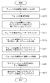
このような背景の下に、従来の半導体装置や電子部品等のチップ製造方法は、図9に示すように、先ず表面に半導体装置や電子部品等が多数形成されたウエーハWの表面を保護するために、片面に粘着剤を有する保護シート(保護テープとも称される)をウエーハ表面に貼る保護シート貼付工程が行われる(ステップS101)。次にウエーハWを裏面から研削して所定の厚さに加工する裏面研削工程が行われる(ステップS103)。 Against this background, as shown in FIG. 9, in the conventional chip manufacturing method for semiconductor devices and electronic components, first, the surface of the wafer W on which a large number of semiconductor devices and electronic components are formed is protected. For this purpose, a protective sheet sticking step is performed in which a protective sheet (also referred to as a protective tape) having an adhesive on one side is attached to the wafer surface (step S101). Next, a back surface grinding step is performed in which the wafer W is ground from the back surface and processed to a predetermined thickness (step S103).
裏面研削工程の後、片面に粘着剤を有するダイシングシート(ダイシングテープとも称される)Sを用いてウエーハWをダイシング用のフレームFに取付けるフレームマウント工程が行われ、ウエーハWとダイシング用のフレームFとが一体化される(ステップS105)。次にこの状態でウエーハWをダイシングシートS側で吸着し、表面に貼付されている保護シートを剥離する保護シート剥離工程が行われる(ステップS107)。 After the back surface grinding process, a frame mounting process for attaching the wafer W to the dicing frame F using a dicing sheet (also referred to as dicing tape) S having an adhesive on one side is performed, and the wafer W and the dicing frame F is integrated (step S105). Next, in this state, a protective sheet peeling process is performed in which the wafer W is adsorbed on the dicing sheet S side and the protective sheet attached to the surface is peeled off (step S107).
保護シートが剥離されたウエーハWは、フレームFごとダイシングソーに搬送され、高速回転するダイヤモンドブレードで個々のチップTに切断される。或いはウエーハWの内部に集光点を合わせたレーザー光を入射し、ウエーハ内部に多光子吸収による改質領域を形成して個々のチップTに分割するレーザーダイシング装置によって個々のチップTに分割される(ステップS109)。分割された個々のチップTは、ダイシングシートSに貼付されたままバラバラにならず、ウェーハ状態を保っているので、ここでは、便宜上このウェーハ状態を保ったチップTの集合体をもウェーハWと呼ぶことにする。 The wafer W from which the protective sheet has been peeled is conveyed to the dicing saw together with the frame F, and is cut into individual chips T by a diamond blade that rotates at high speed. Alternatively, a laser beam having a focused point is incident on the inside of the wafer W, a modified region by multiphoton absorption is formed inside the wafer, and the wafer is divided into individual chips T by a laser dicing apparatus that divides the chips into individual chips T. (Step S109). Since the divided individual chips T remain affixed to the dicing sheet S and remain in the wafer state, here, for convenience, the aggregate of the chips T that have maintained the wafer state is also referred to as the wafer W. I will call it.
次にエキスパンド工程でダイシングシートSが放射状に引き伸ばされて、個々のチップTの間隔が広げられ(ステップS111)、チップマウント工程でリードフレーム等のパッケージ基材にマウントされる(ステップS113)。 Next, the dicing sheet S is radially expanded in the expanding process to widen the intervals between the individual chips T (step S111), and mounted on a package substrate such as a lead frame in the chip mounting process (step S113).
ステップS105のフレームマウント工程では、保護シートが貼付されたウェーハWの主表面側を上にして、ウェーハWの裏面及びウェーハWの外周外側に配置されたリング状のフレームFの裏面とに粘着シートSを貼付し、ウェーハWをフレームFにマウントするウェーハマウンタ(例えば、特許文献1及び2参照。)が用いられる。
ところで、近年ウェーハ主表面のストリートにТEG(Test Elementary Group;プロセス及びデバイスの評価や管理を行うためのテストパターン)が形成されたウェーハWが増えてきた。このようなウェーハWの場合、ウェーハ主表面側からダイシングすると、ダイシングブレードによるダイシングではТEGを形成する金属膜がダイシングブレードに目詰まりを生じさせ、切断時にチップTにチッピングや欠けが生じる。また、レーザーダイシングでは、ウェーハ主表面側からレーザー光を入射させるとТEGが障壁となって上手くダイシングできず、また、ウェーハWの裏面側にはダイシングシートSが貼付されているので裏面側からも上手くダイシングできないという問題があった。 Incidentally, in recent years, the number of wafers W on which ТEG (Test Elementary Group; test patterns for evaluating and managing processes and devices) is formed on the street of the main surface of the wafer has increased. In the case of such a wafer W, when dicing from the main surface side of the wafer, in the dicing by the dicing blade, the metal film forming ТEG causes clogging of the dicing blade, and the chip T is chipped or chipped at the time of cutting. Further, in laser dicing, when laser light is incident from the wafer main surface side, ТEG becomes a barrier and cannot be diced well, and since the dicing sheet S is pasted on the back side of the wafer W, the dicing sheet S is also attached from the back side. There was a problem that dicing did not work well.
このため、ウェーハWの裏面研削の後、ウェーハWの裏面側を上にしてフレームFにマウントし、ウェーハWの裏面側からダイシングする必要があった。この場合チップマウント工程で従来のチップマウンタ(ダイボンダ)をそのまま使用するためには、フレームFにマウントされたまま裏面側からダイシングされたウェーハWを表裏逆転し、主表面を上にしてフレームFにマウントし直さなければならない。 For this reason, after the backside grinding of the wafer W, it is necessary to mount the wafer W on the frame F with the backside of the wafer W facing up and dice from the backside of the wafer W. In this case, in order to use the conventional chip mounter (die bonder) as it is in the chip mounting process, the wafer W diced from the back side while mounted on the frame F is turned upside down, and the main surface is turned up to the frame F. It must be remounted.
しかし、前記の特許文献1及び2に記載のウェーハマウンタは、フレームFにマウントされていないウェーハWをフレームFに自動マウントするもので、既にフレームFにマウントされたウェーハWの表裏を反転させてフレームFに自動でマウントし直すことはできなかった。 However, the wafer mounters described in Patent Documents 1 and 2 automatically mount the wafer W not mounted on the frame F on the frame F, and reverse the front and back of the wafer W already mounted on the frame F. The frame F could not be automatically remounted.
このため、ダイシング工程後に人手によって、ウェーハWの表裏を反転させてフレームFにマウントし直さなければならず、作業工数が掛かるとともに、作業中に誤ってウェーハWを損傷するという危険性があった。 For this reason, the front and back of the wafer W must be reversed and remounted on the frame F manually after the dicing process, which requires a lot of work and a risk of accidentally damaging the wafer W during the work. .
本発明は、このような事情に鑑みてなされたもので、フレームにマウントされたウェーハを、表裏を反転させてフレームに自動でマウントし直すことのできるウェーハマウンタを提供することを目的とする。 The present invention has been made in view of such circumstances, and an object of the present invention is to provide a wafer mounter capable of automatically remounting a wafer mounted on a frame by reversing the front and back of the wafer.
本発明は前記目的を達成するために、ウェーハを粘着シートを介して該ウェーハの外側に配置されたリング状のフレームにマウントするウェーハマウンタにおいて、一方の面側に第1の粘着シートが貼着され該第1の粘着シートを介してリング状の第1のフレームにマウントされたウェーハを、前記第1のフレームから分離するフレーム分離手段と、前記ウェーハの他方の面に第2の粘着シートを貼着し、該第2の粘着シートを介してリング状の第2のフレームにマウントするフレームマウント手段と、を有したことを特徴としている。 In order to achieve the above object, the present invention provides a wafer mounter in which a wafer is mounted on a ring-shaped frame arranged outside the wafer via an adhesive sheet, and the first adhesive sheet is attached to one surface side. And a frame separating means for separating the wafer mounted on the ring-shaped first frame through the first adhesive sheet from the first frame, and a second adhesive sheet on the other surface of the wafer. Frame mounting means for attaching to and mounting on a ring-shaped second frame via the second adhesive sheet.
本発明によれば、一方の面側でフレームにマウントされたウェーハから旧フレームを分離するフレーム分離手段と、旧フレームから分離されたウェーハの他方の面に粘着シートを貼着して新フレームにマウントするフレームマウント手段とを有しているので、フレームにマウントされたウェーハの表裏を反転させて別のフレームに自動でマウントし直すことができる。そのため、裏面からダイシングされたウェーハであっても、従来のチップマウンタ(ダイボンダ)をそのまま用いてチップマウントすることができる。 According to the present invention, the frame separating means for separating the old frame from the wafer mounted on the frame on one surface side, and the adhesive sheet is attached to the other surface of the wafer separated from the old frame to form a new frame. Since the frame mounting means for mounting is provided, the front and back of the wafer mounted on the frame can be reversed and remounted on another frame automatically. Therefore, even a wafer diced from the back side can be chip-mounted using a conventional chip mounter (die bonder) as it is.
また、本発明は、前記ウェーハの一方の面は回路パターンが形成された主表面であり、該主表面には表面を保護する保護シートが貼付されており、前記第2のフレームにマウントされたウェーハの主表面から前記保護シートを剥離するシート剥離手段が設けられていることを付加的要件としている。 Further, according to the present invention, one surface of the wafer is a main surface on which a circuit pattern is formed, and a protective sheet for protecting the surface is attached to the main surface and mounted on the second frame. An additional requirement is that sheet peeling means for peeling the protective sheet from the main surface of the wafer is provided.
この付加的要件によれば、ウェーハの主表面から保護シートを剥離するシート剥離手段が設けられているので、専用の保護シート剥離装置を必要としない。 According to this additional requirement, since a sheet peeling means for peeling the protective sheet from the main surface of the wafer is provided, a dedicated protective sheet peeling device is not required.
また、本発明は、前記ウェーハは前記第1の粘着シートを介して前記第1のフレームと一体化された状態で個々のチップにダイシングされたウェーハであり、前記第2の粘着シートを伸延させることにより前記第2のフレームにマウントされたウェーハの個々のチップ間の間隔を拡大するエキスパンド手段が設けられていることを付加的要件としている。 In the present invention, the wafer is a wafer diced into individual chips in a state of being integrated with the first frame via the first adhesive sheet, and the second adhesive sheet is extended. Accordingly, it is an additional requirement that an expanding means is provided for enlarging the distance between individual chips of the wafer mounted on the second frame.
この付加的要件によれば、ウェーハマウンタにはウェーハの個々のチップ間の間隔を拡大するエキスパンド手段が設けられているので、チップマウント工程への搬送途中で振動によって隣同士のチップが干渉し、チップのエッジ部に微細クラックが生じるのを防止することができる。 According to this additional requirement, since the wafer mounter is provided with expanding means for expanding the distance between individual chips of the wafer, adjacent chips interfere with each other due to vibration during the transfer to the chip mounting process. It is possible to prevent fine cracks from occurring at the edge portion of the chip.
また、本発明は、前記ウェーハの個々のチップ間の間隔が拡大されたエキスパンド状態を保持するエキスパンド保持手段が設けられていることを付加的要件としている。これによれば、個々のチップ間の間隔が拡大されたエキスパンド状態が保持されるので、搬送途中での隣のチップ同士の干渉防止策を必要としない。 In addition, the present invention has an additional requirement that an expansion holding means for holding an expanded state in which a distance between individual chips of the wafer is enlarged is provided. According to this, since the expanded state in which the interval between the individual chips is expanded is maintained, it is not necessary to take measures for preventing interference between adjacent chips during the conveyance.
更に、本発明は、前記第1のフレームと前記第2のフレームとは同種のフレームであることを付加的要件としている。これによれば、第1のフレームと第2のフレームとが同種であるため、ダイシング装置内、ダイシング装置とダイボンダ(チップマウンタ)間、及びダイボンダ(チップマウンタ)内を従来の搬送手段をそのまま用いてフレーム搬送することができる。 Furthermore, the present invention has an additional requirement that the first frame and the second frame are of the same type. According to this, since the first frame and the second frame are of the same type, the conventional conveying means is used as it is in the dicing apparatus, between the dicing apparatus and the die bonder (chip mounter), and in the die bonder (chip mounter). Can be transported by frame.
以上説明したように本発明のウェーハマウンタによれば、フレームにマウントされたウェーハの表裏を反転させて別のフレームに自動でマウントし直すことができる。そのため、裏面からダイシングされたウェーハであっても、従来のチップマウンタをそのまま用いてチップマウントすることができる。 As described above, according to the wafer mounter of the present invention, the front and back of the wafer mounted on the frame can be reversed and automatically mounted on another frame. Therefore, even a wafer diced from the back side can be chip-mounted using a conventional chip mounter as it is.
以下添付図面に従って本発明に係るウェーハマウンタの好ましい実施の形態について詳説する。尚、各図において同一部材には同一の番号または記号を付している。なお、各図においてウェーハやシートの厚さは分り易いように極端に厚く記載してあるが、実際は厚さ100μm程度のものである。 Hereinafter, preferred embodiments of a wafer mounter according to the present invention will be described in detail with reference to the accompanying drawings. In each figure, the same number or symbol is attached to the same member. In each figure, the thickness of the wafer or sheet is shown to be extremely thick so that it can be easily understood, but the actual thickness is about 100 μm.
図1は、本発明に係るウェーハマウンタを表わす平面図である。ウェーハマウンタ10は、インプットカセットエレベータ81A、空フレームカセットエレベータ82A、アウトプットカセットエレベータ83A、搬送ベルトユニット84、84、84、後出図2のフレーム分離手段57、フレームマウント手段50、反転部40、シート剥離手段60、エキスパンド手段30、後出図4のエキスパンド保持手段15、及び搬送手段70等から構成されている。
FIG. 1 is a plan view showing a wafer mounter according to the present invention. The
インプットカセットエレベータ81Aには、第1の粘着シートであるダイシングシートSを介して第1のフレームF1にマウントされた状態でダイシングされ、個々のチップTに分離されたウェーハWが多数枚収納されたインプットカセット81が載置される。
The
空フレームカセットエレベータ82Aには、ウェーハWがマウントされていない空の第2のフレームF2が多数枚収納された空フレームカセット82が載置される。
On the empty
また、アウトプットカセットエレベータ83Aには、第1のフレームF1から第2の粘着シートであるエキスパンドシートESを介して第2のフレームF2に表裏反転してマウントし直されたウェーハWを多数枚格納するアウトプットカセット83が載置される。
In addition, the
インプットカセットエレベータ81A、空フレームカセットエレベータ82A、及びアウトプットカセットエレベータ83Aは、夫々図示しないモータ駆動のボールネジによって上下方向に位置決め駆動される。
The
インプットカセットエレベータ81A、空フレームカセットエレベータ82A、及びアウトプットカセットエレベータ83Aには、夫々搬送ベルトユニット84が設けられ、この搬送ベルトユニット84によって夫々のカセットに対してフレームFの取り出しと収納が行われる。フレームFの取り出しはカセットの最下段から順に取り出し、フレームFを収納する場合はカセットの最上段から順に収納する。
The
反転部40では、ウェーハWがマウントされた第2のフレームF2を吸着した反転吸着台41が、吸着したままの状態で180°回転し、フレームF2を反転させる。この反転動作は図示しないモータ駆動によって行われる。
In the
搬送手段70は、多関節のロボットアームからなり、先端に設けられた4個の吸着盤71、71、…で各フレームFを吸着し、各フレームFををウェーハマウンタ10の各部へ搬送する。多関節のロボットアームは、各関節に設けられた図示しないモータによって回転され、各フレームFを目的地に搬送する。
The transfer means 70 is composed of an articulated robot arm, sucks each frame F with four
図2は、フレームマウント手段50を表わしたものである。図2(a)は、回路パターンWP面に保護シートPSが貼付され、第1の粘着シートであるダイシングシートSを介して第1のフレームF1にマウントされたウェーハWが未だ第1のフレームF1から分離されない状態を表わし、図2(b)は、第1のフレームF1から分離されたウェーハWが第2の粘着シートであるエキスパンドシートESを介して第2のフレームF2にマウントされる状態を表わしている。 FIG. 2 shows the frame mounting means 50. In FIG. 2A, the protective sheet PS is attached to the surface of the circuit pattern WP, and the wafer W mounted on the first frame F1 through the dicing sheet S as the first adhesive sheet is still in the first frame F1. FIG. 2B shows a state in which the wafer W separated from the first frame F1 is mounted on the second frame F2 via the expanded sheet ES that is the second adhesive sheet. It represents.
フレームマウント手段50はウェーハWを吸着載置すると共に上下移動可能な吸着テーブル51、第1のフレームF1を吸着載置するフレームクランパ51A、ウェーハWの外周近傍で下降すると共に回転してダイシングシートSを切断するカッタ(フレーム分離手段)57、第2のフレームF2を載置するフレームホルダ59、供給リール52、巻取りリール53、ガイドローラ54、55、プレスローラ56、第2のフレームF2の外周内側近傍に押付けられて回転しエキスパンドシートESを切断するカッタ58等から構成されている。
The frame mounting means 50 sucks and places the wafer W, and a suction table 51 that can move up and down, a
供給リール52、巻取りリール53、ガイドローラ54、55、プレスローラ56、及びカッタ58は図示しないユニットベースに取り付けられ、吸着テーブル51の上方位置とそこから水平方向に退避した退避位置とに移動されるようになっている。
The
図3(a)は、シート剥離手段60を表わしたものである。シート剥離手段60は、吸着テーブル61、フレームクランパ61A、図1に示す供給リール62と巻取りリール63、剥離シートRS、図示しないプレスローラ、及び図示しない紫外線照射装置等を有している。
FIG. 3A shows the sheet peeling means 60. The sheet peeling means 60 includes a suction table 61, a
剥離すべきシートに剥離シートRSを貼着した後、巻取りリール63が斜め上方に移動し、剥離すべきシートを剥離シートRSごと引き上げて剥離させるようになっている。 After the release sheet RS is attached to the sheet to be peeled, the take-up reel 63 moves obliquely upward, and the sheet to be peeled is pulled up together with the release sheet RS to be peeled off.
図4、図5、図6は、エキスパンド手段30を表わした断面図である。エキスパンド手段30は、ベース11、ベース11に載置された伸縮テーブル12とフレームチャック13、伸縮テーブル12に取り付けられたチャックステージ14、ホルダ16を介してベース11に取り付けられたエキスパンド保持手段である熱風噴射管15等を有している。
4, 5, and 6 are cross-sectional views showing the expanding
チャックステージ14の上面には多孔質部材14Aが埋設され、多孔質部材14Aは電磁弁21B、レギュレータ22Bを経由して真空ポンプ23に接続され、ウェーハWをエキスパンドシートESごと吸着保持するようになっている。
A
また、フレームチャック13の上面にも多孔質部材13Aが埋設され、多孔質部材13Aは電磁弁21A、レギュレータ22Aを経由して真空ポンプ23に接続され、第2のフレームF2をエキスパンドシートESごと吸着保持するようになっている。
A
伸縮テーブル12は、図示しない駆動手段によって上下に伸縮され、チャックステージ14上のウェーハWをエキスパンドシートESごと上下に移動させる。
The telescopic table 12 is vertically expanded and contracted by a driving means (not shown), and moves the wafer W on the
エキスパンド保持手段である熱風噴射管15は、リング状の管で熱風源に接続されており、上面に形成された多数の噴射口15A、15A、…から上方に熱風を噴射する。
The hot
エキスパンドシートESは熱収縮性の粘着シートで、その基材はポリオレフィン系のプラスチックであり、115℃以上の熱が加えられると収縮し、その収縮率は長さ変化率で−15%以上のものが用いられる。ポリオレフィン系の他にポリ塩化ビニル、ポリエステル、ポリスチレン系等のプラスチックから適宜選択することができる。 The expanded sheet ES is a heat-shrinkable pressure-sensitive adhesive sheet, and its base material is a polyolefin-based plastic. It shrinks when heat of 115 ° C or higher is applied, and the shrinkage ratio is -15% or more in terms of the length change rate. Is used. In addition to polyolefin, it can be appropriately selected from plastics such as polyvinyl chloride, polyester and polystyrene.
エキスパンド保持手段である熱風噴射管15は、エキスパンド後のエキスパンドシートESのウェーハWが貼着されていない部分に熱風を照射し、その部分のエキスパンドシートESを熱収縮させてエキスパンド状態を保持する。
The hot-
次に、前述のように構成されたウェーハマウンタ10の作用について説明する。先ず、主表面に形成された回路パターンWPに保護シートPSが貼付され、ダイシングシートSを介して第1のフレームF1に裏面を上にしてマウントされたウェーハWは、多数枚インプットカセット81に収納されてインプットカセットエレベータ81Aに投入される。
Next, the operation of the
次にインプットカセットエレベータ81Aが下降し、インプットカセット81内の最下段のウェーハWが第1のフレームF1ごと搬送ベルトユニット84によって引出される。引出されたウェーハWは、搬送手段70の吸着盤71で第1のフレームF1が吸着されてフレームマウント手段50へ搬送される。
Next, the
フレームマウント手段50では先ず、図2(a)に示すように、ウェーハWが裏面を上にして吸着テーブル51に吸着載置され、第1のフレームF1は吸着テーブル51に設けられたフレームクランパ51Aに吸着される。この状態でフレーム分離手段であるカッタ57が下降してウェーハWの外周に沿って1周し、ダイシングシートSを切断する。これによりウェーハWは第1のフレームから分離される。
In the frame mounting means 50, first, as shown in FIG. 2A, the wafer W is sucked and placed on the suction table 51 with the back side up, and the first frame F1 is a
次に、図2(b)に示すように、吸着テーブル51がウェーハWを吸着載置したまま
上昇し、フレームホルダ59に保持された第2のフレームF2の上面とウェーハWの裏面とが同一高さになるように位置決めする。なお、第2のフレームF2は予め搬送手段70によって空フレームカセット82からフレームホルダ59に搬送され、フレームホルダ59上で待機している。
Next, as shown in FIG. 2B, the suction table 51 is lifted while the wafer W is sucked and placed, and the upper surface of the second frame F2 held by the frame holder 59 and the rear surface of the wafer W are the same. Position it so that it is at the height. The second frame F2 is previously transported from the
一方、供給リール52から繰り出されガイドローラ54、55を経て巻取りリール53に巻き取られるように構成された第2の粘着シートであるエキスパンドシートESが、退避位置から吸着テーブル51の上方に移動する。
On the other hand, the expanded sheet ES, which is a second adhesive sheet configured to be unwound from the
エキスパンドシートESは、貼付け面に紫外線硬化型粘着剤を有しており、プレスローラ56を下方に押圧しながら横方向に転動させることによってウェーハWの裏面、及び第2のフレームF2の上面にエキスパンドシートESが貼付される。
The expand sheet ES has an ultraviolet curable adhesive on the pasting surface, and rolls in the lateral direction while pressing the
その後、カッタ58がエキスパンドシートESに押圧されながら1回転して第2のフレームF2の外周近傍に沿ってエキスパンドシートESを切断し、残ったエキスパンドシートESは巻取りリール23に巻き取られる。この状態でウェーハWはエキスパンドシートESを介して第2のフレームF2に表裏逆転して貼り替えられ、一体化される。
Thereafter, the
なお、第1のフレームF1と第2のフレームF2とが同種同寸法のフレームであると、ダイシング装置とダイボンダ間、及びダイボンダ内を既存の搬送装置を用いてフレーム搬送することができるので好適である。 Note that it is preferable that the first frame F1 and the second frame F2 are frames of the same type and size, because the frame can be transported between the dicing device and the die bonder, and inside the die bonder using an existing transport device. is there.
第2のフレームF2に表裏逆転して貼り替えられたウェーハWは、搬送手段70によって反転部40に搬送される。ここでウェーハWは、反転吸着台41の180°回転により保護シートPSが貼付された主表面側を上に向けて反転される。次いで搬送手段70によってシート剥離手段60へ搬送される。
The wafer W that has been reversed and attached to the second frame F <b> 2 is transferred to the reversing
シート剥離装置60では、ウェーハWは、保護シートPS、ダイシングシートS側を上に、裏面に貼付されたエキスパンドシートES側を下にして吸着テーブル61に吸着載置され、第2のフレームF2は吸着テーブル61に設けられたフレームクランパ61Aに吸着される。
In the
次いで、ウェーハWの主表面側のダイシングシートS側から、図示しない紫外線照射装置によって紫外線を照射する。保護シートPSは紫外線透過型の樹脂が用いられているので、保護シートPSに形成されていた紫外線硬化型粘着剤層が硬化し、ウェーハWとの間の粘着力が低下する。 Next, ultraviolet rays are irradiated from the dicing sheet S side on the main surface side of the wafer W by an ultraviolet irradiation device (not shown). Since UV transmissive resin is used for the protective sheet PS, the UV curable pressure-sensitive adhesive layer formed on the protective sheet PS is cured, and the adhesive force with the wafer W is reduced.
ここで、ウェーハWの主表面側のダイシングシートSに剥離シートRSを貼付し、この剥離シートRSを図3(a)のハッチング矢印で示す方向に引き上げると、ダイシングシートS及び保護シートPSが剥離シートRSに貼着されたままウェーハWから剥離される。これにより、ウェーハWは、図3(b)に示すように、回路パターンWP側を上にして、裏面にエキスパンドシートESが貼付され、第2のフレームF2と一体化された状態となる。 Here, when the release sheet RS is attached to the dicing sheet S on the main surface side of the wafer W and the release sheet RS is pulled up in the direction indicated by the hatching arrow in FIG. 3A, the dicing sheet S and the protective sheet PS are peeled off. It is peeled off from the wafer W while being stuck to the sheet RS. As a result, as shown in FIG. 3B, the wafer W is in a state of being integrated with the second frame F2, with the circuit pattern WP side up, the expand sheet ES being attached to the back surface.
次にウェーハWは、搬送手段70によってエキスパンド手段30へ搬送される。エキスパンド手段30では、このウェーハWをエキスパンドシートESを介してチャックステージ14に載置するとともに第2のフレームF2をフレームチャック13に載置する。ここではウェーハWは既にダイシングされて個々のチップに分割されている。
Next, the wafer W is transferred to the expanding means 30 by the transfer means 70. In the expanding means 30, the wafer W is placed on the
この状態で電磁弁21Aを作動させ、第2のフレームF2をフレームチャック13に吸着固定する。なお、ウェーハWはチャックステージ14に載置したままで、吸着はしない。
In this state, the
次に、伸縮テーブル12を上方に伸ばしウェーハWの貼付されている部分のエキスパンドシートESを上方に持ち上げる。これによりエキスパンドシートESが引き伸ばされて個々のチップT間の間隔が拡大される。図4はこの状態を表わしている。 Next, the expandable table 12 is extended upward, and the expanded sheet ES of the portion where the wafer W is adhered is lifted upward. As a result, the expanded sheet ES is stretched, and the interval between the individual chips T is expanded. FIG. 4 shows this state.
次に、電磁弁21Bを作動させ、ウェーハWをエキスパンドシートESごとチャックステージ14に吸着固定する。これにより、チャックステージ14上のエキスパンドシートESのエキスパンド状態が保持される。
Next, the
この状態から伸縮テーブル12を元の位置まで縮める。チャックステージ14上のエキスパンドシートESは吸着固定されているので、第2のフレームF2とチャックステージ14との間のエキスパンドシートESに弛みSAが生じる。
From this state, the telescopic table 12 is retracted to the original position. Since the expanded sheet ES on the
次に、エキスパンド保持手段である熱風噴射管15の噴射口15A、15A、…からエキスパンドシートESの弛みSAに向けて熱風を噴射する。熱風の温度は120°程度が好適である。エキスパンドシートESは熱収縮性シートであるので、弛みSA部分が収縮して弛みSAが解消される。
Next, hot air is sprayed toward the slack SA of the expanded sheet ES from the
図5は、第2のフレームF2とチャックステージ14との間のエキスパンドシートESに弛みSAが形成され、この弛みSA部分に熱風噴射管15から熱風を噴射している状態を表わしている。
FIG. 5 shows a state in which a slack SA is formed on the expanded sheet ES between the second frame F2 and the
ここで、電磁弁21A、及び21Bを作動させてウェーハWと第2のフレームF2の吸着を解除する。ウェーハWの吸着を解除しても、エキスパンドシートESの弛みSAが収縮し解消しているのでエキスパンドシートESのエキスパンド状態が保持され、個々のチップT間の間隔が拡大されたまま保たれている。図6はこの状態を表わしている。
Here, the
このようにエキスパンドされたエキスパンドシートESのエキスパンド状態が保持され、個々のチップT間の間隔が拡大されているので、個々のチップT同士の接触が防止され、ウェーハWは第2のフレームF2ごと容易に搬送することができる。 Since the expanded state of the expanded sheet ES expanded in this way is maintained, and the interval between the individual chips T is expanded, the contact between the individual chips T is prevented, and the wafer W is provided for each second frame F2. It can be easily transported.
次に、ウェーハWは搬送手段70によってアウトプットカセットに連結する搬送ベルトユニット84上に搬送され、搬送ベルトユニット84の駆動によりアウトプットカセット83内の最上段に収納される。
Next, the wafer W is transferred by the transfer means 70 onto the
同様にして、インプットカセット81内のウェーハWは、第1のフレームF1から分離され、エキスパンドシートESを介して第2のフレームF2に表裏逆転してマウントし直され、表裏反転され、保護シートPSが剥離され、エキスパンドされ、エキスパンド状態が保持され、順次アウトプットカセット83に収納される。
Similarly, the wafer W in the
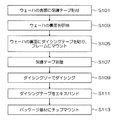
本発明のウェーハマウンタ10を用いることにより、半導体チップ製造工程を図7のフローチャートに示すような新しい工程の流れで行うことができる。この新しい製造工程の流れは、図7に示すように、先ず主表面側に回路パターンが形成されたウェーハWのパターン面を保護するために、パターン面に保護シートPSを貼付する(ステップS11)。
By using the
ステップS11で主表面に保護シートPSが貼付されたウェーハWは、バックグラインダの回転する吸着テーブルに保護シートPS側を下にして吸着され、裏面を回転する砥石で研削され、所定の厚さ(100μm以下)に加工され、次いで吸着テーブルに保持されたまま図示しない研磨ヘッドによって研磨されて、研削加工時に形成された加工変質層が除去される。(ステップS13)。 The wafer W with the protective sheet PS attached to the main surface in step S11 is adsorbed to the rotating adsorption table of the back grinder with the protective sheet PS side down, ground with a grindstone that rotates the back surface, and has a predetermined thickness ( 100 μm or less), and then polished by a polishing head (not shown) while being held on the suction table, the work-affected layer formed during grinding is removed. (Step S13).
次にウェーハWは、フレームマウンタに移され、ダイシングシートSを介して第1のフレームF1に裏面を上にしてマウントされ、一体化される(ステップS15)。 Next, the wafer W is transferred to the frame mounter, mounted on the first frame F1 via the dicing sheet S with the back surface facing up, and integrated (step S15).
第1のフレームF1と一体化されたウェーハWは、カセットに多数枚収納されてレーザーダイシング装置に投入される。レーザーダイシング装置では、ウェーハWを赤外線を使用して裏面からアライメントし、裏面からウェーハ内部に集光点を有するレーザー光を入射し、ウェーハ内部に改質領域を形成してウェーハWを割断する(ステップS17)。 A large number of wafers W integrated with the first frame F1 are stored in a cassette and put into a laser dicing apparatus. In the laser dicing apparatus, the wafer W is aligned from the back surface using infrared rays, laser light having a condensing point is incident on the inside of the wafer from the back surface, a modified region is formed inside the wafer, and the wafer W is cleaved ( Step S17).
このときウェーハ主表面のストリートにТEGがあっても、ウェーハWの裏面からレーザー光を入射するので、ТEGが障壁となって上手くダイシングできないという問題は解消される。 At this time, even if there is ТEG on the street of the main surface of the wafer, the laser light is incident from the back surface of the wafer W, so that the problem that the dicing cannot be performed successfully due to ТEG as a barrier is solved.
次に、レーザーダイシングされたウェーハWは、本発明のウェーハマウンタ10に搬送され、先ず図2に示すように、第1のフレームから分離され(ステップS19)、次いでエキスパンドシートESを介して第2のフレームF2に表裏逆転して貼り替えられ、一体化される(ステップS21)。
Next, the laser-diced wafer W is transferred to the
次に、第2のフレームF2に貼り替えられたウェーハWは、図3(a)に示すように、保護シートPSが剥離され、図3(b)に示すように、回路パターンWP側を上にして、裏面にエキスパンドシートESが貼付されて第2のフレームF2と一体化された状態となる(ステップS23)。 Next, as shown in FIG. 3A, the protective sheet PS is peeled off from the wafer W attached to the second frame F2, and the circuit pattern WP side is turned up as shown in FIG. 3B. Then, the expanded sheet ES is pasted on the back surface and integrated with the second frame F2 (step S23).
次に、図4、図5、図6に示すように、エキスパンドシートESが放射状に引き伸ばされて個々のチップ間隔が拡大され、このエキスパンド状態が保持される(ステップS25)。このステップ19からステップ25までの工程が本発明のウェーハマウンタ10で行われる。
Next, as shown in FIGS. 4, 5, and 6, the expanded sheet ES is stretched radially to increase the interval between the individual chips, and this expanded state is maintained (step S <b> 25). The processes from step 19 to step 25 are performed by the
次に、ウェーハWはダイボンダに搬送され、ダイボンダでは個々のチップTを1個ずつコレットでピックアップし、リードフレーム等のパッケージ基板にダイボンディング(チップマウント)する(ステップS27)。 Next, the wafer W is transferred to a die bonder, and the die bonder picks up individual chips T one by one with a collet and die-bonds (chip mounts) to a package substrate such as a lead frame (step S27).
以上が本発明のウェーハマウンタ10を用いた新しいチップ製造方法の工程の流れである。このように、ウェーハWをレーザーダイシングするので、100μm以下の極薄のウェーハWであっても、チッピングや欠けのないチップTを製造することができる。また、シート材を介さずウェーハの裏面から直接レーザー光を入射させるので、安定したレーザー割断が行えるとともに、ストリートにTEGの形成されたウェーハWであっても十分割断することができる。
The above is the process flow of the new chip manufacturing method using the
更に、本発明のウェーハマウンタ10では、レーザーダイシング後にウェーハWの表裏を逆にして別のフレームに貼り替えるので、ダイシング装置内、ダイシング装置とダイボンダ間、及びダイボンダ内を既存の搬送装置を用いてフレーム搬送することができる。
Further, in the
なお、前述した本実施の形態では、ダイシングシートSとエキスパンドシートESとを夫々別の物を用いたが、ダイシングシートSは一般的に伸張性のよいものが用いられているので、エキスパンドシートESの代わりにダイシングシートSを用いてもよい。 In the above-described embodiment, the dicing sheet S and the expanded sheet ES are different from each other. However, since the dicing sheet S generally has a good extensibility, the expanded sheet ES is used. A dicing sheet S may be used instead.
また、エキスパンド手段30は、第2のフレームF2を固定してウェーハWを上下移動するように構成したが、ウェーハWを固定して第2のフレームF2を上下移動するようにしてもよい。 The expanding means 30 is configured to move the wafer W up and down with the second frame F2 fixed, but it may be configured to move the second frame F2 up and down with the wafer W fixed.
また、エキスパンドシートESに熱収縮性のシートを用い、エキスパンド保持手段15は、エキスパンドシートESに熱風を噴射する構成としたが、熱風に限らず、電熱式のヒートプレート等を用いてもよい。またエキスパンドシートESに熱収縮性のシートを用いず、機械的にエキスパンド状態を保持させる構成であってもよい。 In addition, although a heat-shrinkable sheet is used for the expanded sheet ES and the expanded holding means 15 is configured to inject hot air to the expanded sheet ES, it is not limited to hot air, and an electrothermal heat plate or the like may be used. Further, the expanded sheet ES may be configured to mechanically hold the expanded state without using a heat-shrinkable sheet.
10…ウェーハマウンタ、15…熱風噴射管(エキスパンド保持手段)、30…エキスパンド手段、40…反転部、50…フレームマウント手段、57…カッタ(フレーム分離手段)、60…シート剥離手段、70…搬送手段、ES…エキスパンドシート(第2の粘着シート)、F…フレーム、F1…第1のフレーム、F2…第2のフレーム、PS…保護シート、RS…剥離シート、S…ダイシングシート(第1の粘着シート、粘着シート)、T…チップ、W…ウエーハ、WP…回路パターン
DESCRIPTION OF
Claims (5)
一方の面側に第1の粘着シートが貼着され該第1の粘着シートを介してリング状の第1のフレームにマウントされたウェーハを、前記第1のフレームから分離するフレーム分離手段と、
前記ウェーハの他方の面に第2の粘着シートを貼着し、該第2の粘着シートを介してリング状の第2のフレームにマウントするフレームマウント手段と、を有したことを特徴とするウェーハマウンタ。 In a wafer mounter that mounts a wafer on a ring-shaped frame disposed outside the wafer via an adhesive sheet,
A frame separating means for separating the wafer mounted on the ring-shaped first frame via the first pressure-sensitive adhesive sheet and having the first pressure-sensitive adhesive sheet attached to one surface side from the first frame;
Frame mounting means for attaching a second adhesive sheet to the other surface of the wafer and mounting the second adhesive sheet on a ring-shaped second frame via the second adhesive sheet. Mounter.
Priority Applications (1)
| Application Number | Priority Date | Filing Date | Title |
|---|---|---|---|
| JP2004149162A JP4324788B2 (en) | 2004-05-19 | 2004-05-19 | Wafer mounter |
Applications Claiming Priority (1)
| Application Number | Priority Date | Filing Date | Title |
|---|---|---|---|
| JP2004149162A JP4324788B2 (en) | 2004-05-19 | 2004-05-19 | Wafer mounter |
Publications (2)
| Publication Number | Publication Date |
|---|---|
| JP2005332931A true JP2005332931A (en) | 2005-12-02 |
| JP4324788B2 JP4324788B2 (en) | 2009-09-02 |
Family
ID=35487374
Family Applications (1)
| Application Number | Title | Priority Date | Filing Date |
|---|---|---|---|
| JP2004149162A Expired - Fee Related JP4324788B2 (en) | 2004-05-19 | 2004-05-19 | Wafer mounter |
Country Status (1)
| Country | Link |
|---|---|
| JP (1) | JP4324788B2 (en) |
Cited By (14)
| Publication number | Priority date | Publication date | Assignee | Title |
|---|---|---|---|---|
| JP2006278630A (en) * | 2005-03-29 | 2006-10-12 | Lintec Corp | Wafer transfer apparatus |
| JP2007311570A (en) * | 2006-05-18 | 2007-11-29 | Lintec Corp | Replacing device and replacing method |
| JP2008028130A (en) * | 2006-07-20 | 2008-02-07 | Lintec Corp | Method and device for repasting |
| JP2012059994A (en) * | 2010-09-10 | 2012-03-22 | Tokyo Ohka Kogyo Co Ltd | Holding device |
| JP2012244012A (en) * | 2011-05-20 | 2012-12-10 | Lintec Corp | Transfer device and transfer method |
| WO2014002535A1 (en) * | 2012-06-29 | 2014-01-03 | シャープ株式会社 | Semiconductor device manufacturing method |
| JP2014007216A (en) * | 2012-06-22 | 2014-01-16 | Lintec Corp | Sheet application apparatus and application method |
| JP2014150233A (en) * | 2013-02-04 | 2014-08-21 | Lintec Corp | Sheet sticking apparatus and sticking method |
| JP2016143720A (en) * | 2015-01-30 | 2016-08-08 | リンテック株式会社 | Sheet transfer device and transfer method |
| JP2016178244A (en) * | 2015-03-20 | 2016-10-06 | リンテック株式会社 | Sheet peeling device and peeling method and sheet transfer device |
| JP2017162870A (en) * | 2016-03-07 | 2017-09-14 | 日東電工株式会社 | Substrate transfer method and substrate transfer device |
| JP2019054108A (en) * | 2017-09-14 | 2019-04-04 | リンテック株式会社 | Separation device and separation method |
| JP2020031165A (en) * | 2018-08-24 | 2020-02-27 | 株式会社タカトリ | Adhesive tape re-sticking device and re-sticking method for substrate |
| JP2020031166A (en) * | 2018-08-24 | 2020-02-27 | 株式会社タカトリ | Adhesive tape peeling device and peeling method |
-
2004
- 2004-05-19 JP JP2004149162A patent/JP4324788B2/en not_active Expired - Fee Related
Cited By (20)
| Publication number | Priority date | Publication date | Assignee | Title |
|---|---|---|---|---|
| JP2006278630A (en) * | 2005-03-29 | 2006-10-12 | Lintec Corp | Wafer transfer apparatus |
| JP2007311570A (en) * | 2006-05-18 | 2007-11-29 | Lintec Corp | Replacing device and replacing method |
| JP4632313B2 (en) * | 2006-05-18 | 2011-02-16 | リンテック株式会社 | Pasting device and pasting method |
| JP2008028130A (en) * | 2006-07-20 | 2008-02-07 | Lintec Corp | Method and device for repasting |
| JP4643514B2 (en) * | 2006-07-20 | 2011-03-02 | リンテック株式会社 | Pasting device and pasting method |
| JP2012059994A (en) * | 2010-09-10 | 2012-03-22 | Tokyo Ohka Kogyo Co Ltd | Holding device |
| JP2012244012A (en) * | 2011-05-20 | 2012-12-10 | Lintec Corp | Transfer device and transfer method |
| JP2014007216A (en) * | 2012-06-22 | 2014-01-16 | Lintec Corp | Sheet application apparatus and application method |
| WO2014002535A1 (en) * | 2012-06-29 | 2014-01-03 | シャープ株式会社 | Semiconductor device manufacturing method |
| JP2014150233A (en) * | 2013-02-04 | 2014-08-21 | Lintec Corp | Sheet sticking apparatus and sticking method |
| JP2016143720A (en) * | 2015-01-30 | 2016-08-08 | リンテック株式会社 | Sheet transfer device and transfer method |
| JP2016178244A (en) * | 2015-03-20 | 2016-10-06 | リンテック株式会社 | Sheet peeling device and peeling method and sheet transfer device |
| JP2017162870A (en) * | 2016-03-07 | 2017-09-14 | 日東電工株式会社 | Substrate transfer method and substrate transfer device |
| WO2017154304A1 (en) * | 2016-03-07 | 2017-09-14 | 日東電工株式会社 | Substrate transfer method and substrate transfer device |
| JP2019054108A (en) * | 2017-09-14 | 2019-04-04 | リンテック株式会社 | Separation device and separation method |
| JP7002260B2 (en) | 2017-09-14 | 2022-01-20 | リンテック株式会社 | Separation device and separation method |
| JP2020031165A (en) * | 2018-08-24 | 2020-02-27 | 株式会社タカトリ | Adhesive tape re-sticking device and re-sticking method for substrate |
| JP2020031166A (en) * | 2018-08-24 | 2020-02-27 | 株式会社タカトリ | Adhesive tape peeling device and peeling method |
| JP7290814B2 (en) | 2018-08-24 | 2023-06-14 | 株式会社タカトリ | Adhesive tape peeling device and peeling method |
| JP7392964B2 (en) | 2018-08-24 | 2023-12-06 | 株式会社タカトリ | Adhesive tape re-applying device and re-applying method for substrates |
Also Published As
| Publication number | Publication date |
|---|---|
| JP4324788B2 (en) | 2009-09-02 |
Similar Documents
| Publication | Publication Date | Title |
|---|---|---|
| JP3560823B2 (en) | Wafer transfer device | |
| JP4324788B2 (en) | Wafer mounter | |
| JP5253996B2 (en) | Work dividing method and tape expansion device | |
| WO1997008745A1 (en) | Method and apparatus for peeling protective adhesive tape from semiconductor wafer | |
| JP2004047823A (en) | Dicing tape sticking device and back grind dicing tape sticking system | |
| CN110491783B (en) | Wafer processing method | |
| JP2003152058A (en) | Wafer transfer apparatus | |
| JP2007305628A (en) | Processing system and method therefor | |
| JP4505789B2 (en) | Chip manufacturing method | |
| CN110802509B (en) | Protective member forming apparatus | |
| JP2007173770A (en) | Re-taping process, and method of dividing substrate using same | |
| JP2006191144A (en) | Pickup device and pickup method | |
| JP6695173B2 (en) | Substrate transfer method and substrate transfer apparatus | |
| JP2005123653A (en) | Taping/peering apparatus and taping system | |
| JP2011224642A (en) | Protective material and ablation processing method | |
| JP2010135356A (en) | Dicing method of wafer | |
| JP2007134510A (en) | Wafer mounter | |
| JP3618080B2 (en) | Die bonding sheet sticking apparatus and die bonding sheet sticking method | |
| JP2000331963A (en) | Method and device for mounting wafer to wafer frame and facing device incorporating mounting device | |
| JP2005045149A (en) | Method for expansion | |
| JP4768963B2 (en) | Wafer transfer method | |
| JP2013041908A (en) | Method of dividing optical device wafer | |
| JP4385705B2 (en) | Expanding method | |
| JP2005260154A (en) | Method of manufacturing chip | |
| JP2002353296A (en) | Equipment for peeling wafer protective tape and wafer mounting equipment |
Legal Events
| Date | Code | Title | Description |
|---|---|---|---|
| A621 | Written request for application examination |
Free format text: JAPANESE INTERMEDIATE CODE: A621 Effective date: 20060907 |
|
| A977 | Report on retrieval |
Free format text: JAPANESE INTERMEDIATE CODE: A971007 Effective date: 20090216 |
|
| A131 | Notification of reasons for refusal |
Free format text: JAPANESE INTERMEDIATE CODE: A131 Effective date: 20090218 |
|
| A521 | Request for written amendment filed |
Free format text: JAPANESE INTERMEDIATE CODE: A523 Effective date: 20090417 |
|
| TRDD | Decision of grant or rejection written | ||
| A01 | Written decision to grant a patent or to grant a registration (utility model) |
Free format text: JAPANESE INTERMEDIATE CODE: A01 Effective date: 20090513 |
|
| A01 | Written decision to grant a patent or to grant a registration (utility model) |
Free format text: JAPANESE INTERMEDIATE CODE: A01 |
|
| A61 | First payment of annual fees (during grant procedure) |
Free format text: JAPANESE INTERMEDIATE CODE: A61 Effective date: 20090526 |
|
| FPAY | Renewal fee payment (event date is renewal date of database) |
Free format text: PAYMENT UNTIL: 20120619 Year of fee payment: 3 |
|
| R150 | Certificate of patent or registration of utility model |
Ref document number: 4324788 Country of ref document: JP Free format text: JAPANESE INTERMEDIATE CODE: R150 Free format text: JAPANESE INTERMEDIATE CODE: R150 |
|
| FPAY | Renewal fee payment (event date is renewal date of database) |
Free format text: PAYMENT UNTIL: 20120619 Year of fee payment: 3 |
|
| FPAY | Renewal fee payment (event date is renewal date of database) |
Free format text: PAYMENT UNTIL: 20130619 Year of fee payment: 4 |
|
| R250 | Receipt of annual fees |
Free format text: JAPANESE INTERMEDIATE CODE: R250 |
|
| R250 | Receipt of annual fees |
Free format text: JAPANESE INTERMEDIATE CODE: R250 |
|
| R250 | Receipt of annual fees |
Free format text: JAPANESE INTERMEDIATE CODE: R250 |
|
| R250 | Receipt of annual fees |
Free format text: JAPANESE INTERMEDIATE CODE: R250 |
|
| R250 | Receipt of annual fees |
Free format text: JAPANESE INTERMEDIATE CODE: R250 |
|
| R250 | Receipt of annual fees |
Free format text: JAPANESE INTERMEDIATE CODE: R250 |
|
| R250 | Receipt of annual fees |
Free format text: JAPANESE INTERMEDIATE CODE: R250 |
|
| R250 | Receipt of annual fees |
Free format text: JAPANESE INTERMEDIATE CODE: R250 |
|
| R250 | Receipt of annual fees |
Free format text: JAPANESE INTERMEDIATE CODE: R250 |
|
| R250 | Receipt of annual fees |
Free format text: JAPANESE INTERMEDIATE CODE: R250 |
|
| R250 | Receipt of annual fees |
Free format text: JAPANESE INTERMEDIATE CODE: R250 |
|
| LAPS | Cancellation because of no payment of annual fees |