JP2005299979A - Exhaust gas treatment apparatus and exhaust gas treatment method for rotary hearth type reduction furnace - Google Patents
Exhaust gas treatment apparatus and exhaust gas treatment method for rotary hearth type reduction furnace Download PDFInfo
- Publication number
- JP2005299979A JP2005299979A JP2004114331A JP2004114331A JP2005299979A JP 2005299979 A JP2005299979 A JP 2005299979A JP 2004114331 A JP2004114331 A JP 2004114331A JP 2004114331 A JP2004114331 A JP 2004114331A JP 2005299979 A JP2005299979 A JP 2005299979A
- Authority
- JP
- Japan
- Prior art keywords
- exhaust gas
- gas treatment
- rotary hearth
- reduction furnace
- zinc
- Prior art date
- Legal status (The legal status is an assumption and is not a legal conclusion. Google has not performed a legal analysis and makes no representation as to the accuracy of the status listed.)
- Granted
Links
Images
Classifications
-
- Y—GENERAL TAGGING OF NEW TECHNOLOGICAL DEVELOPMENTS; GENERAL TAGGING OF CROSS-SECTIONAL TECHNOLOGIES SPANNING OVER SEVERAL SECTIONS OF THE IPC; TECHNICAL SUBJECTS COVERED BY FORMER USPC CROSS-REFERENCE ART COLLECTIONS [XRACs] AND DIGESTS
- Y02—TECHNOLOGIES OR APPLICATIONS FOR MITIGATION OR ADAPTATION AGAINST CLIMATE CHANGE
- Y02P—CLIMATE CHANGE MITIGATION TECHNOLOGIES IN THE PRODUCTION OR PROCESSING OF GOODS
- Y02P10/00—Technologies related to metal processing
- Y02P10/20—Recycling
-
- Y—GENERAL TAGGING OF NEW TECHNOLOGICAL DEVELOPMENTS; GENERAL TAGGING OF CROSS-SECTIONAL TECHNOLOGIES SPANNING OVER SEVERAL SECTIONS OF THE IPC; TECHNICAL SUBJECTS COVERED BY FORMER USPC CROSS-REFERENCE ART COLLECTIONS [XRACs] AND DIGESTS
- Y02—TECHNOLOGIES OR APPLICATIONS FOR MITIGATION OR ADAPTATION AGAINST CLIMATE CHANGE
- Y02P—CLIMATE CHANGE MITIGATION TECHNOLOGIES IN THE PRODUCTION OR PROCESSING OF GOODS
- Y02P10/00—Technologies related to metal processing
- Y02P10/25—Process efficiency
Landscapes
- Waste-Gas Treatment And Other Accessory Devices For Furnaces (AREA)
- Manufacture And Refinement Of Metals (AREA)
- Manufacture Of Iron (AREA)
- Tunnel Furnaces (AREA)
Abstract
【課題】 亜鉛を含む酸化鉄粒子と炭素を主体とする粒子の混合物を還元する回転炉床式還元炉の排ガス中の亜鉛含有ダストを高品位の状態で回収し、且つ、排ガス処理装置を小型化することを目的とする。
【解決手段】 亜鉛を含む酸化金属と炭素を含む粒子の混合物を還元する回転炉床式還元炉2の排ガス処理において、排ガス処理装置を、排ガス煙道水平部10、廃熱ボイラー12、熱交換機13、バグフィルター式集塵機14の構成とする。排ガス煙道水平部10を通過する際の排ガス流速が1.7〜8m/秒、廃熱ボイラー12を通過する際の排ガス流速が2〜8m/秒、熱交換器13を通過する際の排ガス流速が2〜7m/秒であり、かつ、バグフィルター式集塵機14での排ガス水分比率を40容積%以下とする。
【選択図】 図1PROBLEM TO BE SOLVED: To recover zinc-containing dust in exhaust gas of a rotary hearth type reduction furnace that reduces a mixture of iron oxide particles containing zinc and particles mainly composed of carbon, and to reduce the size of the exhaust gas treatment device. It aims to become.
In exhaust gas treatment of a rotary hearth type reduction furnace 2 for reducing a mixture of metal oxide containing zinc and particles containing carbon, an exhaust gas treatment device includes an exhaust gas flue horizontal portion 10, a waste heat boiler 12, a heat exchanger. 13. It is set as the structure of the bag filter type dust collector 14. The exhaust gas flow rate when passing through the exhaust gas flue horizontal portion 10 is 1.7 to 8 m / second, the exhaust gas flow velocity when passing through the waste heat boiler 12 is 2 to 8 m / second, and the exhaust gas when passing through the heat exchanger 13 The flow rate is 2 to 7 m / sec, and the exhaust gas moisture ratio in the bag filter type dust collector 14 is 40% by volume or less.
[Selection] Figure 1
Description
本発明は、亜鉛を含む酸化鉄粒子と炭素を主体とする粒子の混合物を還元する回転炉床式還元炉において、還元反応に伴って排ガスとともに発生する亜鉛含有ダストを高品位の状態で回収する技術に関する。また、アルカリとハロゲンの塩を含む亜鉛含有ダストを適正に処理する方法にも関する。 The present invention recovers zinc-containing dust generated together with exhaust gas in a high-quality state in a rotary hearth type reduction furnace that reduces a mixture of iron oxide particles containing zinc and particles mainly composed of carbon. Regarding technology. The present invention also relates to a method for properly treating zinc-containing dust containing alkali and halogen salts.
最近は、鉄鉱石を還元して還元鉄を製造する操業や、鉄鋼製造工程で発生する酸化鉄を含むダストやスラッジを処理する処理には、回転炉床式還元炉を用いることが行われている。回転炉床式還元炉は、耐火物の固定天井と固定壁の下を、中央を欠いた円盤状の耐火物炉床が回転する型式の炉である。酸化鉄や酸化ニッケルを還元する操業では、粉体を10〜25mmの大きさの成形体を1100〜1400℃で還元する。炉内の熱供給速度が大きいため、還元時間は10〜30分間である。 Recently, a rotary hearth type reduction furnace has been used for operations to reduce iron ore to produce reduced iron and to treat dust and sludge containing iron oxide generated in the steel production process. Yes. A rotary hearth type reduction furnace is a type of furnace in which a disk-shaped refractory hearth lacking a center rotates under a fixed ceiling and a fixed wall of a refractory. In the operation of reducing iron oxide or nickel oxide, a compact having a size of 10 to 25 mm is reduced at 1100 to 1400 ° C. Since the heat supply rate in the furnace is large, the reduction time is 10 to 30 minutes.
回転炉床式還元炉では、1200℃程度の温度で、一酸化炭素雰囲気で還元する酸化物である、酸化鉄、酸化ニッケルなどを還元することが可能である。これらの酸化物を還元する際には、原料に混合している酸化亜鉛も還元される。炉内で金属化した亜鉛は、1100℃以上では、蒸気となって、還元された成形体から分離されて、排ガス中に移行する。この亜鉛蒸気は、排ガスとともに炉外に排出されて、排ガス処理装置の集塵機で捕集される。 In the rotary hearth type reduction furnace, it is possible to reduce iron oxide, nickel oxide, and the like, which are oxides reduced in a carbon monoxide atmosphere at a temperature of about 1200 ° C. When these oxides are reduced, zinc oxide mixed in the raw material is also reduced. Zinc metallized in the furnace becomes vapor at 1100 ° C. or higher, is separated from the reduced shaped body, and moves into the exhaust gas. This zinc vapor is discharged out of the furnace together with the exhaust gas, and is collected by the dust collector of the exhaust gas treatment device.
従って、回転炉床式還元炉は、亜鉛を多く含む酸化鉄、例えば、高炉ガスダスト、転炉ガスダストや電炉ダストを処理することにも使用されている。この目的の処理においては、金属鉄などを製造すること以外にも、ダスト等の脱亜鉛も可能であり、脱亜鉛プロセスとしても活用されている。 Therefore, the rotary hearth type reduction furnace is also used to treat iron oxides rich in zinc, for example, blast furnace gas dust, converter gas dust, and electric furnace dust. In the treatment for this purpose, in addition to producing metallic iron and the like, dezincification of dust and the like is possible, and it is also utilized as a dezincing process.
このように、回転炉床式還元炉は、亜鉛濃縮プロセスとしても効率の高いプロセスである。例えば、亜鉛を1質量%含有している酸化鉄粉体を還元処理する場合には、排ガスダスト中の亜鉛濃度は45〜60質量%と高濃度に濃縮することが可能である。このように、回転炉床式還元炉で濃縮された高亜鉛ダストは、金属亜鉛製造の原料として使用することができる。 Thus, the rotary hearth type reduction furnace is a highly efficient process as a zinc concentration process. For example, when reducing the iron oxide powder containing 1% by mass of zinc, the zinc concentration in the exhaust gas dust can be concentrated to a high concentration of 45 to 60% by mass. Thus, the high zinc dust concentrated in the rotary hearth type reducing furnace can be used as a raw material for producing metal zinc.
回転炉床式還元炉の亜鉛含有ダストを亜鉛原料として利用することは、資源リサイクルの観点からは、重要な技術である。例えば、従来技術の例である特許文献1に記載される方法においては、排ガスを冷却して、この中に含まれるダストを集塵機で回収することを効率的に行う技術である。しかし、排ガス処理装置の内部にダストが付着することを防止して、これを健全に保つことには有効であったものの、亜鉛含有ダストを高品位で、かつ、回収の操作が簡易である状態で回収して、これをリサイクル資源として利用することには、十分な配慮がなされてこなかった。この結果、亜鉛含有ダストを亜鉛原料として使用する際の価値が低下する問題があった。つまり、操業条件が不適切な場合は、原料の酸化鉄粉などが排ガス中に同伴されて、これが排ガス処理の集塵機で、酸化亜鉛の粉体に混在していた。この結果、亜鉛含有ダストの亜鉛含有率が低くなっていた。このように、従来技術においては、亜鉛含有ダストに、原料が粉化した粒子が混在する問題があった。 Utilizing zinc-containing dust from a rotary hearth reducing furnace as a zinc raw material is an important technology from the viewpoint of resource recycling. For example, in the method described in Patent Document 1 as an example of the prior art, the exhaust gas is cooled and the dust contained therein is efficiently collected by a dust collector. However, although it was effective to prevent dust from adhering to the inside of the exhaust gas treatment device and keep it healthy, the zinc-containing dust is high-quality and the operation of recovery is simple However, sufficient consideration has not been given to recovering and using it as a recycling resource. As a result, there has been a problem that the value when using zinc-containing dust as a zinc raw material is lowered. That is, when the operating conditions are inappropriate, the raw material iron oxide powder or the like is accompanied in the exhaust gas, and this is a dust collector for exhaust gas treatment and is mixed in the zinc oxide powder. As a result, the zinc content of the zinc-containing dust was low. As described above, in the prior art, there is a problem that particles containing raw materials are mixed in the zinc-containing dust.
また、亜鉛含有ダストに混在する塩化ナトリウムなどの物質の影響があり、これも問題であった。例えば、特許文献2に記載されるように、亜鉛含有ダストにはアルカリ塩(塩化ナトリウム、塩化カリウム、フッ化ナトリウムなどのアルカリとハロゲンの塩)が含有されることが多い。回転炉床式還元炉で水素を含む燃料ガスを燃焼したり、排ガス冷却に水噴霧を行ったりすることにより、排ガス中の水比率が高い場合には、アルカリ塩に関連する次の問題があった。排ガス中水分が多い場合は、排ガス温度が低い集塵機の内部で結露しやすくなる。この結果、水を吸収すると付着しやすいアルカリ塩がダスト中に含まれると、バグフィルター式集塵機などでは、フィルターにダストが付着する問題が生じていた。このような場合には、集塵機での排ガスの圧力損失は大きくなり、排ガス処理が安定して行えない問題が生じていた。 Moreover, there was an influence of substances such as sodium chloride mixed in the zinc-containing dust, which was also a problem. For example, as described in Patent Document 2, zinc-containing dust often contains an alkali salt (an alkali and halogen salt such as sodium chloride, potassium chloride, or sodium fluoride). If the water ratio in the exhaust gas is high by burning fuel gas containing hydrogen in the rotary hearth reduction furnace or performing water spray for exhaust gas cooling, there are the following problems related to alkali salts. It was. When there is a lot of moisture in the exhaust gas, condensation tends to occur inside the dust collector where the exhaust gas temperature is low. As a result, when an alkali salt that easily adheres when water is absorbed is contained in the dust, the bag filter type dust collector or the like has a problem that dust adheres to the filter. In such a case, the pressure loss of the exhaust gas in the dust collector becomes large, causing a problem that the exhaust gas treatment cannot be performed stably.
このように、回転炉床式還元炉の排ガスを適正に処理することは重要であり、従来技術では、幾つかの問題があったが、更に、大量生産を行うための装置では、排ガス処理装置が大型化する問題もあった。回転炉床式還元炉から出る排ガスに含まれるダストが排ガス出口ダクトに沈殿蓄積する問題があった、この問題を解決するために、特許文献2に記載される装置などでは、排ガス出口ダクトを上向きとして、かつ、その水平面に対する角度を45度以上とすることにより、ダストを滑り落とすことが行われていた。この装置においては、排ガス出口ダクトの頂部高さが過大となり、場合によっては、ダクト頂部高さが25m以上となることもあった。このダクトと廃熱ボイラーなどの排ガス処理装置の高さも高くなり、装置が巨大化して、排ガス処理装置の建設費用が多くかかる結果となっていた。 As described above, it is important to appropriately treat the exhaust gas of the rotary hearth type reduction furnace, and there have been some problems in the prior art. Further, in the apparatus for mass production, the exhaust gas treatment apparatus There was also a problem of increasing the size. In order to solve this problem, the dust contained in the exhaust gas discharged from the rotary hearth type reduction furnace has settled and accumulated in the exhaust gas outlet duct. In addition, the dust is slid down by setting the angle with respect to the horizontal plane to 45 degrees or more. In this apparatus, the top height of the exhaust gas outlet duct is excessive, and in some cases, the height of the duct top is 25 m or more. The height of the exhaust gas treatment apparatus such as the duct and the waste heat boiler is also increased, resulting in a large apparatus and a high construction cost of the exhaust gas treatment apparatus.
以上に説明したように、回転炉床式還元炉の排ガスを冷却して、集塵する技術においては、技術的な問題があり、この問題を解決することが求められていた。また、排ガス中に含まれる亜鉛含有ダストの品位を向上させて、亜鉛原料として使用することについても、幾つかの課題があった。このように、回転炉床式還元炉の排ガス及び亜鉛含有ダストの処理を改善するための新しい技術が求められていた。 As described above, there is a technical problem in the technique of cooling and collecting dust from the rotary hearth type reduction furnace, and it has been required to solve this problem. Moreover, there existed some subjects also about improving the quality of the zinc containing dust contained in waste gas, and using it as a zinc raw material. Thus, a new technique for improving the treatment of exhaust gas and zinc-containing dust in a rotary hearth type reduction furnace has been demanded.
本発明は、上記の技術的問題を解決するためのものであり、次に記載する(1)から(9)の通りである。
(1)加熱ゾーンおよび還元ゾーンを有する回転炉床式還元炉の排ガス処理装置において、該加熱ゾーンの炉側壁に設置された排ガスの排出口と、該排出口からつながる排ガス煙道水平部と、該煙道水平部からつながる排ガス冷却装置と、その後段の熱交換器と、更に後段のバグフィルター式集塵機を有することを特徴とする回転炉床式還元炉の排ガス処理装置。
(2)前記排ガス冷却装置が廃熱ボイラーであることを特徴とする(1)記載の回転炉床式還元炉の排ガス処理装置。
(3)前記排ガス冷却装置が排ガス中への水噴霧による冷却装置であることを特徴とする(1)記載の回転炉床式還元炉の排ガス処理装置。
(4)前記排ガス煙道水平部の通路断面積(単位:m2)が該煙道水平部を通過する排ガス流量(単位:Nm3/秒)の0.65倍以上2.4倍以下であることを特徴とする(1)〜(3)のいずれかに記載の回転炉床式還元炉の排ガス処理装置。
(5)(1)〜(4)のいずれかの装置を用いた排ガス処理方法であって、亜鉛および酸化金属を含む粒子並びに炭素を主体とする粒子の混合物である原料を、液体燃料または気体燃料を用いて加熱して、該原料中の該酸化金属を還元し、生じた排ガスを、前記排ガス冷却装置にて300℃以上500℃以下まで冷却し、更に前記熱交換器で130℃以上220℃以下とし、前記バグフィルター式集塵機で排ガス中の亜鉛を含むダストを集塵することを特徴とする回転炉床式還元炉の排ガス処理方法。
(6)前記排ガス煙道水平部での排ガス流速を1.7m/秒以上8m/秒以下とし、かつ、煙道内で沈降したダストを煙道下部から排出することを特徴とする(5)記載の回転炉床式還元炉の排ガス処理方法。
(7)前記廃熱ボイラーでの排ガス流速を2m/秒以上8m/秒以下とすることを特徴とする(5)または(6)記載の回転炉床式還元炉の排ガス処理方法。
(8)前記熱交換器での排ガス流速を2m/秒以上7m/秒以下とすることを特徴とする(5)〜(7)のいずれかに記載の回転炉床式還元炉の排ガス処理方法。
(9)アルカリ金属および/またはハロゲン元素を1.0〜8.0質量%含む前記原料に対し、前記バグフィルター式集塵機内部での排ガス水分比率を40容積%以下とすることを特徴とする(5)〜(8)のいずれかに記載の回転炉床式還元炉の排ガス処理方法。
The present invention is for solving the above technical problems, and is as described in (1) to (9) below.
(1) In an exhaust gas treatment apparatus of a rotary hearth type reduction furnace having a heating zone and a reduction zone, an exhaust gas exhaust port installed on a furnace side wall of the heating zone, an exhaust gas flue horizontal part connected from the exhaust port, An exhaust gas treatment device for a rotary hearth type reduction furnace, comprising an exhaust gas cooling device connected from the horizontal portion of the flue, a heat exchanger at the subsequent stage, and a bag filter type dust collector at the subsequent stage.
(2) The exhaust gas treatment apparatus for a rotary hearth reducing furnace according to (1), wherein the exhaust gas cooling apparatus is a waste heat boiler.
(3) The exhaust gas treatment apparatus for a rotary hearth type reduction furnace according to (1), wherein the exhaust gas cooling apparatus is a cooling apparatus by spraying water into the exhaust gas.
(4) The cross-sectional area (unit: m 2 ) of the exhaust gas flue horizontal portion is 0.65 times or more and 2.4 times or less of the exhaust gas flow rate (unit: Nm 3 / sec) passing through the flue horizontal portion. The exhaust gas treatment apparatus for a rotary hearth type reduction furnace according to any one of (1) to (3), wherein:
(5) An exhaust gas treatment method using the apparatus according to any one of (1) to (4), wherein a raw material that is a mixture of particles containing zinc and metal oxide and particles mainly composed of carbon is used as liquid fuel or gas The metal oxide in the raw material is reduced by heating with fuel, and the generated exhaust gas is cooled to 300 ° C. or higher and 500 ° C. or lower by the exhaust gas cooling device, and further 130 ° C. or higher and 220 ° C. by the heat exchanger. An exhaust gas treatment method for a rotary hearth type reduction furnace, wherein the dust containing zinc in the exhaust gas is collected by the bag filter type dust collector at a temperature of not higher than ° C.
(6) The exhaust gas flow velocity in the horizontal portion of the flue gas flue is set to 1.7 m / second or more and 8 m / second or less, and dust settled in the flue is discharged from the lower portion of the flue. Exhaust gas treatment method for rotary hearth type reduction furnace.
(7) The exhaust gas treatment method for a rotary hearth type reduction furnace according to (5) or (6), wherein an exhaust gas flow rate in the waste heat boiler is 2 m / second or more and 8 m / second or less.
(8) The exhaust gas treatment method for a rotary hearth type reducing furnace according to any one of (5) to (7), wherein an exhaust gas flow velocity in the heat exchanger is 2 m / second or more and 7 m / second or less. .
(9) The exhaust gas moisture ratio inside the bag filter type dust collector is 40% by volume or less with respect to the raw material containing 1.0 to 8.0% by mass of alkali metal and / or halogen element ( The exhaust gas treatment method for a rotary hearth type reduction furnace according to any one of 5) to (8).
本発明の排ガス処理装置を用いることにより、排ガス処理装置内部でのダスト沈降や付着の問題がなくなることから、安定した回転炉床式還元炉の操業を長時間にわたって行えるともに、高品位の亜鉛含有ダストを高収率で回収できる。また、本発明の排ガス処理装置は小型であることから、建設費用を大幅に低減することができる。例えば、特許文献2で示されるような回転炉床式還元炉の排ガス出口ダクトが水平面に対して45度以上上向きとなっているような装置と比較して、回転炉床式還元炉から水平方向に排ガスを抜く構造となっている本発明の排ガス処理装置では、廃熱ボイラーの最高部の位置を約8m低くすることができ、その結果、廃熱ボイラーの設置費用が20%低減された。 By using the exhaust gas treatment apparatus of the present invention, there is no problem of dust settling and adhesion inside the exhaust gas treatment apparatus, so that stable rotary hearth reduction furnace operation can be performed for a long time, and high-grade zinc content is included. Dust can be recovered with high yield. Moreover, since the exhaust gas treatment apparatus of the present invention is small, construction costs can be significantly reduced. For example, as compared with an apparatus in which the exhaust gas outlet duct of a rotary hearth type reduction furnace as shown in Patent Document 2 is upwards of 45 degrees or more with respect to a horizontal plane, the rotary hearth type reduction furnace is set in a horizontal direction. In the exhaust gas treatment apparatus of the present invention having a structure for exhausting the exhaust gas, the position of the highest part of the waste heat boiler can be lowered by about 8 m. As a result, the installation cost of the waste heat boiler is reduced by 20%.
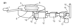
図1に示すように、造粒装置1にて、亜鉛を含有する酸化金属の粒子と炭素を含有する粒子の混合物を成形体として、これを加熱ゾーン8と還元ゾーン9を有する回転炉床式還元炉2で還元する。加熱ゾーン8は主として温度を所定の温度まで上昇させる帯域であり、還元ゾーン9は主として発生する一酸化炭素ガスまたは原料中の炭素により原料中の金属酸化物を還元する帯域のことである。本発明の対象となる酸化金属は、酸化鉄、酸化ニッケル、酸化マンガンなどの1000℃以上の一酸化炭素雰囲気等で還元される酸化金属である。これらの酸化金属の粉体と炭素を含む粉体を混合して、10〜30mmの大きさの成形体を作る。
As shown in FIG. 1, in a granulating apparatus 1, a mixture of metal oxide particles containing zinc and particles containing carbon is used as a compact, and this is a rotary hearth type having a
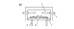
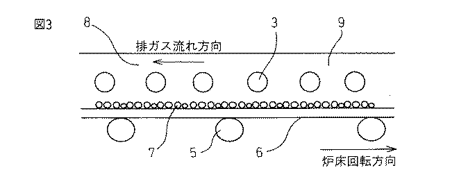
この成形体を回転炉床式還元炉2の内部で、図2に示すように、バーナー3からの火炎4の輻射熱で、炉床6の上の成形体7を加熱して、これを焼成還元する。図3に示すように、車輪5によって駆動される炉床6の回転に伴い、成形体7は、完全燃焼雰囲気の加熱ゾーン8で1100℃程度まで加熱されて、更に、還元雰囲気の還元ゾーン9に移動して、ここで1100〜1400℃の温度で還元される。還元反応に伴い、回転炉床式還元炉2の炉内では、還元された亜鉛が蒸発して、成形体7から抜ける。また、成形体7にはアルカリ塩が含まれており、これも1000℃以上では、蒸発して、成形体7から抜ける。また、回転炉床式還元炉2の排ガス中には、原料の成形体7の粉が飛散した酸化鉄、酸化ニッケル等の粒子も混在する。なお、炉内では、排ガスは成形体7の載っている炉床6の回転方向と反対方向に移動する。
As shown in FIG. 2, this compact is heated in the rotary hearth type reduction furnace 2 by the radiant heat of the flame 4 from the
この亜鉛とアルカリ塩の蒸気は、排ガスとともに炉内を移動して、加熱ゾーン8の側壁に設置されている排ガスの排出口18から、図1に示される排ガス煙道水平部10に入る。なお、排ガス煙道水平部10は、ほぼ水平方向に排ガスを流す構造の煙道である。ここでの排ガス温度は850〜1200℃である。このように、排ガスを横方向に排出することにより、排ガスダクトの頂部が高くなることを防止して、排ガス処理装置を小型化することができる。
The zinc and alkali salt vapors move in the furnace together with the exhaust gas, and enter the exhaust gas flue
本発明者らの研究では、このような排ガス煙道水平部10の構成では、排ガス煙道内のダスト堆積を防止することが重要であることが判明した。したがって、本発明の設備で、排ガス煙道水平部10でのダスト堆積防止のためには、排ガス煙道水平部10では、排ガス流速を1.7〜8m/秒とすることが望ましい。そのため、設計の段階で、原料成分、燃焼バーナー用の燃料使用量、導入空気量等から、発生するガスの流量範囲を推定し、排ガス流速が1.7〜8m/秒に入るように、煙道水平部10の断面積を決定する。また、操業時には、バーナー燃焼量と導入空気量を調整して対応する。排ガス流速1.7m/秒以下の場合は、酸化亜鉛粒子の一部がこの部分に沈降、蓄積して、良質な亜鉛原料して回収される亜鉛含有ダストの収率が低下する。また、沈降ダスト排出部11に酸化亜鉛粒子が大量に蓄積して、ダスト払い出し周期が短くなり、稼働率が低下する問題もある。一方、排ガス流速を8m/秒以上では、真比重が大きく、かつ、粗粒である酸化鉄や酸化ニッケルの粒子が排ガス処理装置の後流に送られる問題が生じる。この結果、廃熱ボイラー12や熱交換器13でのこのダストが原因の付着や摩耗が起きる問題や、最終的に回収された亜鉛含有ダストの亜鉛品位が低下する問題が起きる。このような条件を満たすためには、設備条件として、排ガス煙道水平部10の通路断面積(単位:m2)が通過する排ガス流量(単位:Nm3/秒)の0.65〜2.4倍であることが良い。
In the research by the present inventors, it has been found that in such a configuration of the exhaust gas flue
続いて、排ガスと亜鉛含有ダストは廃熱ボイラー12に入る。ここで、排ガスは冷却され、300〜500℃程度となる。廃熱ボイラー12内部での排ガス流速は2m/秒以上であることが良く、また、8m/秒以下であることが望ましい。そのため、設計の段階で、原料成分、燃焼バーナー用の燃料使用量、導入空気量等から、発生するガスの流量範囲を推定し、排ガス流速が2〜8m/秒に入るように、廃熱ボイラー12内部の断面積を決定する。また、操業時には、バーナー燃焼量と導入空気量を調整して対応する。本発明者らの研究の結果、廃熱ボイラー12内部の構造から、排ガス流速は2m/秒以下では、この部分での亜鉛含有ダストの沈降にともなう付着が発生する問題が起きることが判った。また、8m/秒以上では、廃熱ボイラーのチューブ表面の摩耗問題が起きることも判った。
Subsequently, the exhaust gas and zinc-containing dust enter the
廃熱ボイラー12を出た排ガスは、熱交換器13に入り、ここで燃焼用空気の予熱などに排ガスの顕熱を使い、130〜220℃まで冷却する。熱交換器13内部での排ガス流速は2〜7m/秒であることが良い。そのため、設計の段階で、原料成分、燃焼バーナー用の燃料使用量、導入空気量等から、発生するガスの流量範囲を推定し、排ガス流速が2〜8m/秒に入るように、熱交換器13内部の断面積を決定する。また、操業時には、バーナー燃焼量と導入空気量を調整して対応する。廃熱ボイラー12と同様に熱交換器13での排ガス流速の適正な範囲は、やはり亜鉛含有ダストの沈降をコントロールすることで決まる値である。排ガス流速が熱交換器10内部で2m/秒以下である場合は、酸化亜鉛粒子が排ガス経路の狭い部分で沈降し、付着してしまう。この結果、酸化亜鉛粒子の収率が低下する問題と、熱交換器13の内部でのダスト付着による閉塞の問題が生ずる。また、熱交換器13の内部での排ガス流速が7m/秒以上では、やはり熱交換面の摩耗の問題が起きる。なお、廃熱ボイラー12や熱交換器13には、ダスト落とし装置が設置してあると、更に、以上の問題が小さくなるため、これは有効な手段である。
The exhaust gas exiting the
この温度まで冷却された排ガスは、バグフィルター式集塵機14で除塵される。その後、排ガスは、誘引排風機15を経由して、煙突16から大気に放散される。集塵方式は、いずれの方法でも可能であるが、良質な亜鉛含有ダストを集めるためには、細かい粒子の集塵に最適な方式であるバグフィルター式集塵機を用いることが良い。一方、バグフィルター式集塵機14で集められた亜鉛含有ダストは、ダストビン17に蓄えられる。この亜鉛含有ダストはトータル亜鉛比率が45〜60質量%の高純度の亜鉛原料として亜鉛精錬等で使用される。精錬方法としては、硫酸水溶液に溶解して、これを電気分解することにより、電気亜鉛を製造する方法や、溶鉱炉の原料として、金属亜鉛を製造する方法などがある。
The exhaust gas cooled to this temperature is removed by the bag filter
また、本発明の方法では、原料中にアルカリ金属および/またはハロゲン元素を1.0〜8.0質量%含む場合は、排ガスを集塵する際の排ガス中水分を40容積%以下とすることにより、バグフィルター式の集塵機14における詰まりを防止でき、当該装置の操業支障回避の効果がある。回転炉床式還元炉2では、燃料として、重油、軽油、天然ガス、コークス炉ガスなどの液体又は気体燃料を用いる。これらの燃料中には水素が含まれており、燃焼後には、これが水蒸気となる。従って、回転炉床式還元炉2の排ガス中には、15〜25容積%程度の水分が含まれている。本発明者らの実験では、15〜25容積%程度の水分を含んでいても、130℃以上の排ガス温度であれば、バグフィルター式集塵機14での集塵での問題は起きなかった。しかし、水噴霧を行って排ガスを冷却する排ガス処理を行った場合は、排ガス水分が40容積%程度以上となることがある。この排ガスをバグフィルター式集塵機14で集塵する場合は、フィルターに操業上の問題が生ずることから、本発明では、この条件を避けることが望ましい。
In the method of the present invention, when alkali metal and / or halogen element is contained in the raw material in an amount of 1.0 to 8.0% by mass, the moisture in the exhaust gas when collecting the exhaust gas should be 40% by volume or less. Thus, clogging in the bag filter
すなわち、本発明者らが、水分40容積%以上の排ガス条件でのバグフィルターの内部の温度、ガス流れ、フィルターに付着した亜鉛含有ダストの化学分析を行ったところ、以下のことが判明した。排ガス温度が140〜220℃の条件においても、バグフィルターの局部では、温度が100℃以下の部分があり、この部分では、フィルターの表面に亜鉛含有ダストが付着していた。この部分では、排ガスのフィルターでの抜けが極端に悪化していた。本発明者らが、この付着物を分析したところ、この亜鉛含有ダストに含まれるアルカリ塩が水分を含み、潮解していることが確認された。これは、バグフィルター式の集塵機14内部の排ガス温度が低い部分で、アルカリ塩が排ガス中の水分を吸っていたことが原因であった。従って、集塵機14の位置での排ガス中水分は40容積%以下とすることが望ましい。ただし、バグフィルター式の集塵機14での排ガス温度が130℃前後と低い場合は、水分は35容積%以下に下げることが更に好ましい。原料中のアルカリ金属および/またはハロゲン元素の含有量が1.0質量%以下と低い場合には、このような現象は生じない。また、通常は製鉄所等で発生するダスト等には、アルカリ金属および/またはハロゲン元素が多くても8.0質量%以下である。
That is, the present inventors conducted the chemical analysis of the temperature inside the bag filter, the gas flow, and the zinc-containing dust adhering to the filter under the exhaust gas condition with a water content of 40% by volume or more, and found the following. Even under conditions where the exhaust gas temperature is 140 to 220 ° C., there is a portion where the temperature is 100 ° C. or less in the local part of the bag filter, and zinc-containing dust adheres to the surface of the filter in this portion. In this part, the exhaust gas through the filter was extremely deteriorated. When the present inventors analyzed this deposit | attachment, it was confirmed that the alkali salt contained in this zinc containing dust contains a water | moisture content and is deliquescent. This was due to the fact that the alkali salt had absorbed moisture in the exhaust gas at the portion where the exhaust gas temperature inside the bag filter
従来技術では、排ガスダクト内への水噴霧で、排ガスを冷却する方法が一般に行われている。水噴霧による排ガス冷却では、850〜1200℃の排ガスを400〜500℃まで冷却して、その後に、熱交換器13で冷却することが行われている。又は、廃熱回収を行わない場合は、水噴霧で850〜1200℃の排ガスを150〜200℃程度まで冷却することが行われている。この方法では、排ガス1立方メートル当り200〜500kgの水を吹き込まなければならず、排ガス中水分が20〜40容積%増加する。この結果、バグフィルター式集塵機での排ガス中水分が35又は40容積%以上となるため、前述した亜鉛含有ダスト中のアルカリ塩の潮解現象が生じてしまう。本発明の装置で行う排ガス処理では、排ガス中の水分を増加させないために、排ガス冷却に、水噴霧を行わずに、排ガス処理装置を廃熱ボイラー12、熱交換器13、及び、バグフィルター式の集塵機14の構成とする。この装置構成の中で、前述したように、排ガス流速を適正な範囲とすることは、良質な亜鉛含有ダストを採取するためには有効な手段である。ただし、設備建設費を低減する目的としては、バグフィルター式集塵機14での排ガス中水分が35又は40容積%を越さない範囲で、排ガス冷却装置12の一部を水噴霧で行うこともある。例えば、1000℃から700℃までを水噴霧で冷却して、700℃から400℃を小型の廃熱ボイラー12で、また、400℃から180℃を熱交換器13で冷却することでも良い。
In the prior art, a method of cooling the exhaust gas by spraying water into the exhaust gas duct is generally performed. In exhaust gas cooling by water spraying, exhaust gas at 850 to 1200 ° C. is cooled to 400 to 500 ° C., and then cooled by the
本発明の条件を満たす設備として、図1から図3に記載される回転炉床式還元炉で、亜鉛を含む製鉄ダストを還元処理した実施例を示す。回転炉床式還元炉は炉床面積が200平方メートルのものであった。排ガス煙道水平部10の排ガス流線方向の断面積は15平方メートルであった。原料の主成分は、酸化鉄65〜68質量%、又、炭素が12〜15質量%であった。更に、この原料は、亜鉛を0.9〜1.2質量%、又、アルカリ塩を0.15〜0.25質量%の比率で含むものである。この操業結果を表1に示す。
As equipment satisfying the conditions of the present invention, an embodiment in which iron-making dust containing zinc is reduced in the rotary hearth type reduction furnace shown in FIGS. 1 to 3 will be described. The rotary hearth type reducing furnace had a hearth area of 200 square meters. The cross-sectional area of the exhaust gas flue
還元ゾーン9の温度を1300℃として還元処理を行い、成形体の処理量を22トン/時とした。燃料は比較的水素の少ない重油を用いた。この操業では、平均排ガス発生量は39,000Nm3/時であった。従って、排ガス煙道水平部10の排ガス流線方向の断面積1m2当り0.72Nm3/秒であり、この排ガス処理装置の構成は本発明に記載される範囲のものである。また、この処理での排ガスの水蒸気は23容積%であった。排ガス中の含塵濃度は1Nm3あたり112gであった。加熱ゾーン8の炉側壁に設置された排ガスの排出口8での亜鉛含有ダストの化学成分は、トータル亜鉛53質量%、トータル鉄4.2質量%、アルカリ塩(NaCl、NaF、KCl、KFの合計)16質量%であった。
The reduction treatment was performed at a temperature of the reduction zone 9 of 1300 ° C., and the processing amount of the compact was 22 tons / hour. The fuel used was heavy oil with relatively little hydrogen. In this operation, the average exhaust gas generation amount was 39,000 Nm 3 / hour. Accordingly, the cross-sectional area of the exhaust gas flue
排ガスの排ガス煙道水平部10での流速は3.7m/秒であり、この部分では、一部の粗い酸化鉄粒子の沈殿が認められたものの、大部分の亜鉛含有ダストは廃熱ボイラー12に移行していた。この部分で沈殿して回収されたダスト量は全体の1.3質量%であり、平均成分はトータル鉄21質量%、トータル亜鉛28質量%であった。このように、沈殿ダスト量は少なく、また、酸化亜鉛比率も低いものであり、排出作業の問題はなかった。廃熱ボイラー12内部の排ガス流速は5.0m/秒であり、又、熱交換器13内部の排ガス流速は3.8m/秒であり、本発明の適正な範囲であった。これらの装置の内部で沈降したダストを集めて、秤量と成分分析を行った。この測定の結果、この処理では、廃熱ボイラー12と熱交換器13に沈降したダストは、全体の2.9質量%であり、平均成分はトータル鉄13質量%、トータル亜鉛31質量%であった。このように、沈殿ダスト量は少ないとともに、亜鉛濃度の低いものであった。このように、本発明の排ガス処理条件を守ることにより、排ガスのルートでのダスト沈殿による経路閉塞の問題や、酸化亜鉛ロスの問題を解決することができた。
The flow rate of the exhaust gas at the
上記の条件で、165℃まで冷却した排ガスをバグフィルター式の集塵機14で除塵した。この条件では、アルカリ塩への水分の吸収はなく、亜鉛含有ダストがフィルター表面に固着することがなかった。集塵機14で回収された亜鉛含有ダストは水分が低いことから、流動性の良い粒子であった。この亜鉛含有ダストを備蓄する際や搬送する際の問題はなかった。また、排ガス冷却経路では、酸化亜鉛の沈降が少なかったことから、亜鉛含有ダストのトータル亜鉛濃度は55質量%と高品位であり、また、高純度の亜鉛含有ダストが採取できる集塵機14での亜鉛含有ダストの回収比率(原料中の全亜鉛量中の回収亜鉛量の割合?)は98%と極めて高かった。
〔実施例2〕
Under the above conditions, the exhaust gas cooled to 165 ° C. was removed by the bag filter
[Example 2]
実施例1に記載した原料の成形体を用いて、還元ゾーン温度1300℃で還元処理を行い、成形体の処理量を17トン/時とした。この際の、平均排ガス発生量は33,000Nm3/時であった。従って、排ガス煙道水平部10の排ガス流線方向の断面積1m2当り0.61Nm3/時であった。この処理での排ガス水蒸気が29容積%であった。排ガス中の含塵濃度は1Nm3あたり103gであった。
Using the molded body of the raw material described in Example 1, reduction treatment was performed at a reduction zone temperature of 1300 ° C., and the throughput of the molded body was 17 tons / hour. The average amount of exhaust gas generated at this time was 33,000 Nm 3 / hour. Thus, was when the exhaust gas flue
排ガスの排ガス煙道水平部10での流速は2.9m/秒であり、この部分では、一部の酸化鉄粒子の沈殿が認められた。沈殿して回収されたダスト量は全体の1.1質量%であり、平均成分はトータル鉄11質量%、トータル亜鉛21.5質量%であった。廃熱ボイラー12内部の排ガス流速は3.8m/秒であり、又、熱交換器13内部の排ガス流速は3.0m/秒であった。上記の条件で、150℃まで冷却した排ガスを集塵機14で除塵した。この条件では、アルカリ塩への水分の吸収はなく、亜鉛含有ダストがフィルター表面に固着することがなかった。この亜鉛含有ダストを備蓄する際や搬送する際の問題はなかった。また、亜鉛含有ダストのトータル亜鉛濃度は56質量%と高品位であり、また、亜鉛含有ダスト回収率は97%と良好であった。この処理でも、排ガスのルートでのダスト沈殿による経路閉塞の問題や、酸化亜鉛ロスの問題を解決することができた。
〔実施例3〕
The flow rate of the exhaust gas at the exhaust gas flue
Example 3
実施例1に記載した原料の成形体を用いて、還元ゾーン温度1280℃で還元処理を行ったが、廃熱ボイラー12をバイパスして水噴霧装置で排ガスを冷却して、その後に、排ガスを熱交換器13と集塵機14で亜鉛含有ダストを回収した。表1に示すように、排ガス処理装置内でのガス流速は適正に保たれていたことから、亜鉛含有ダスト回収比率は95%と高かった。しかし、集塵機内排ガス中水分が46容積%と高かったため、集塵機14での亜鉛含有ダスト付着の問題があった。この結果、集塵機14のフィルターの目詰まりが起きて、約2週間に一度の頻度で、フィルターの掃除が必要となった。
The raw material molded body described in Example 1 was used for reduction treatment at a reduction zone temperature of 1280 ° C., but the
〔比較例1〕
操業条件は、実施例1〜3とほぼ同じであるが、排ガス処理装置内部での排ガス流速が遅い処理の例を比較例1として示す。処理条件と排ガスの状態は、表1に示すとおりである。ただし、排ガス発生量が16,000ノーマル立方メートル/時と少なかったことから、煙道水平部9で1.3m/秒、廃熱ボイラー12内で1.8m/秒、又、熱交換器13内部で1.3m/秒と本発明の範囲を外れていた。この結果、排ガス処理装置内の各々の部分でダスト沈降に関わる問題が起き、又、亜鉛含有ダスト回収率が85%と低位であった。このように、本発明の条件を満たす3例の実施例においては、熱交換器13等の内部でのダスト沈降などの操業上の問題が生じず、また、亜鉛含有ダスト回収率も高かったものの、比較例1では、種々の問題が起きた。
[Comparative Example 1]
Although the operating conditions are substantially the same as those of Examples 1 to 3, an example of treatment with a slow exhaust gas flow rate inside the exhaust gas treatment apparatus is shown as Comparative Example 1. The processing conditions and the state of the exhaust gas are as shown in Table 1. However, since the amount of exhaust gas generated was as small as 16,000 normal cubic meters / hour, 1.3 m / second in the flue horizontal portion 9, 1.8 m / second in the
〔比較例2〕
図1から図3に記載されるものと類似した回転炉床式還元炉であるが、排ガスの出口煙道が上方に設置されている排ガス処理装置を装備した還元炉での操業結果である。この排ガス処理装置では、当該煙道の流れ方向は水平面から60度の角度であり、当該煙道の頂部の高さは18mであった。本発明の装置では、廃熱ボイラー12を設置する場合は、廃熱ボイラー12の高さが12mとなり、設備設置費用が大幅に増加することが判明した。この理由で、廃熱ボイラー12の換わりに、水噴霧冷却装置を設置した。この還元炉を用いて、実施例1と同じ亜鉛を含む製鉄ダストを還元処理した実施例を示す。回転炉床式還元炉は炉床面積が200m2のものであった。この装置は、図1と図2に記載される装置よりも排ガス処理装置が大きくなる問題があった。また、排ガス冷却に水噴霧装置を用いた結果、排ガス中の水分が41容積%となり、集塵機14での亜鉛含有ダスト付着の問題が起きた。
[Comparative Example 2]
It is a rotary hearth type reduction furnace similar to that described in FIGS. 1 to 3, but is the result of operation in a reduction furnace equipped with an exhaust gas treatment device in which the exhaust gas flue is installed above. In this exhaust gas treatment apparatus, the flow direction of the flue was 60 degrees from the horizontal plane, and the height of the top of the flue was 18 m. In the apparatus of the present invention, when the
1…造粒装置
2…回転炉床式還元炉
3…バーナー
4…火炎
5…車輪
6…炉床
7…成形体
8…加熱ゾーン
9…還元ゾーン
10…排ガス煙道水平部
11…沈降ダスト排出部
12…廃熱ボイラー(排ガス冷却装置)
13…熱交換器
14…バグフィルター式集塵機
15…誘引排風機
16…煙突
17…ダストビン
DESCRIPTION OF SYMBOLS 1 ... Granulator 2 ... Rotary hearth
13 ...
Claims (9)
Priority Applications (1)
| Application Number | Priority Date | Filing Date | Title |
|---|---|---|---|
| JP2004114331A JP4328256B2 (en) | 2004-04-08 | 2004-04-08 | Exhaust gas treatment apparatus and exhaust gas treatment method for rotary hearth type reduction furnace |
Applications Claiming Priority (1)
| Application Number | Priority Date | Filing Date | Title |
|---|---|---|---|
| JP2004114331A JP4328256B2 (en) | 2004-04-08 | 2004-04-08 | Exhaust gas treatment apparatus and exhaust gas treatment method for rotary hearth type reduction furnace |
Publications (2)
| Publication Number | Publication Date |
|---|---|
| JP2005299979A true JP2005299979A (en) | 2005-10-27 |
| JP4328256B2 JP4328256B2 (en) | 2009-09-09 |
Family
ID=35331727
Family Applications (1)
| Application Number | Title | Priority Date | Filing Date |
|---|---|---|---|
| JP2004114331A Expired - Fee Related JP4328256B2 (en) | 2004-04-08 | 2004-04-08 | Exhaust gas treatment apparatus and exhaust gas treatment method for rotary hearth type reduction furnace |
Country Status (1)
| Country | Link |
|---|---|
| JP (1) | JP4328256B2 (en) |
Cited By (17)
| Publication number | Priority date | Publication date | Assignee | Title |
|---|---|---|---|---|
| WO2009131242A1 (en) * | 2008-04-25 | 2009-10-29 | Jfeスチール株式会社 | Process for production of direct-reduced iron |
| JP2009281617A (en) * | 2008-05-20 | 2009-12-03 | Nippon Steel Engineering Co Ltd | Exhaust gas treatment method for rotary hearth furnace |
| JP2010007181A (en) * | 2008-05-30 | 2010-01-14 | Jfe Steel Corp | Method for producing reduced iron |
| JP2010007182A (en) * | 2008-05-30 | 2010-01-14 | Jfe Steel Corp | Method for producing reduced iron |
| JP2010007180A (en) * | 2008-05-30 | 2010-01-14 | Jfe Steel Corp | Method for producing pig iron by using iron ore with high content of zinc |
| JP2010031355A (en) * | 2008-04-25 | 2010-02-12 | Jfe Steel Corp | Method for producing luppe using high zinc-content iron ore |
| JP2010031356A (en) * | 2008-04-25 | 2010-02-12 | Jfe Steel Corp | Method for producing reduced iron using high zinc-content iron ore |
| CN102062534A (en) * | 2010-06-22 | 2011-05-18 | 四川龙蟒矿冶有限责任公司 | Method and device for heat supply of rotary hearth furnace |
| JP2012500902A (en) * | 2008-08-30 | 2012-01-12 | タータ スチール リミテッド | A method of separating iron from iron ore containing high-concentration zinc and extracting iron and valuable materials |
| JP2012506308A (en) * | 2008-10-23 | 2012-03-15 | シーメンス・ファオアーイー・メタルズ・テクノロジーズ・ゲーエムベーハー | Method and apparatus for separating particulate solid from gas flow |
| JP2013515850A (en) * | 2009-12-23 | 2013-05-09 | シーメンス・ファオアーイー・メタルズ・テクノロジーズ・ゲーエムベーハー | Method and apparatus for supplying reducing gas from generator gas |
| CN103836997A (en) * | 2013-11-29 | 2014-06-04 | 偏关县晋电化工有限责任公司 | Flue gas waste heat utilization system of rotary kiln |
| CN104215083A (en) * | 2014-09-28 | 2014-12-17 | 朱宗林 | Smoke discharge and dust removal desulphurization device for movable type rotating tunnel kiln |
| CN105004193A (en) * | 2015-07-28 | 2015-10-28 | 中国恩菲工程技术有限公司 | Heat exchange system capable of recycling waste heat of reduction furnace |
| JP2018104733A (en) * | 2016-12-22 | 2018-07-05 | 住友金属鉱山株式会社 | Method for producing zinc oxide ore |
| CN111607416A (en) * | 2020-05-27 | 2020-09-01 | 国家电投集团黄河上游水电开发有限责任公司 | A kind of petroleum coke calcining rotary kiln connected to flue |
| CN113739587A (en) * | 2021-09-15 | 2021-12-03 | 熊骏 | Ferrosilicon ore flue gas waste heat treatment device based on heat exchange principle |
-
2004
- 2004-04-08 JP JP2004114331A patent/JP4328256B2/en not_active Expired - Fee Related
Cited By (18)
| Publication number | Priority date | Publication date | Assignee | Title |
|---|---|---|---|---|
| WO2009131242A1 (en) * | 2008-04-25 | 2009-10-29 | Jfeスチール株式会社 | Process for production of direct-reduced iron |
| JP2010031355A (en) * | 2008-04-25 | 2010-02-12 | Jfe Steel Corp | Method for producing luppe using high zinc-content iron ore |
| JP2010031356A (en) * | 2008-04-25 | 2010-02-12 | Jfe Steel Corp | Method for producing reduced iron using high zinc-content iron ore |
| JP2009281617A (en) * | 2008-05-20 | 2009-12-03 | Nippon Steel Engineering Co Ltd | Exhaust gas treatment method for rotary hearth furnace |
| JP2010007181A (en) * | 2008-05-30 | 2010-01-14 | Jfe Steel Corp | Method for producing reduced iron |
| JP2010007182A (en) * | 2008-05-30 | 2010-01-14 | Jfe Steel Corp | Method for producing reduced iron |
| JP2010007180A (en) * | 2008-05-30 | 2010-01-14 | Jfe Steel Corp | Method for producing pig iron by using iron ore with high content of zinc |
| JP2012500902A (en) * | 2008-08-30 | 2012-01-12 | タータ スチール リミテッド | A method of separating iron from iron ore containing high-concentration zinc and extracting iron and valuable materials |
| JP2012506308A (en) * | 2008-10-23 | 2012-03-15 | シーメンス・ファオアーイー・メタルズ・テクノロジーズ・ゲーエムベーハー | Method and apparatus for separating particulate solid from gas flow |
| JP2013515850A (en) * | 2009-12-23 | 2013-05-09 | シーメンス・ファオアーイー・メタルズ・テクノロジーズ・ゲーエムベーハー | Method and apparatus for supplying reducing gas from generator gas |
| CN102062534A (en) * | 2010-06-22 | 2011-05-18 | 四川龙蟒矿冶有限责任公司 | Method and device for heat supply of rotary hearth furnace |
| CN103836997A (en) * | 2013-11-29 | 2014-06-04 | 偏关县晋电化工有限责任公司 | Flue gas waste heat utilization system of rotary kiln |
| CN104215083A (en) * | 2014-09-28 | 2014-12-17 | 朱宗林 | Smoke discharge and dust removal desulphurization device for movable type rotating tunnel kiln |
| CN105004193A (en) * | 2015-07-28 | 2015-10-28 | 中国恩菲工程技术有限公司 | Heat exchange system capable of recycling waste heat of reduction furnace |
| JP2018104733A (en) * | 2016-12-22 | 2018-07-05 | 住友金属鉱山株式会社 | Method for producing zinc oxide ore |
| CN111607416A (en) * | 2020-05-27 | 2020-09-01 | 国家电投集团黄河上游水电开发有限责任公司 | A kind of petroleum coke calcining rotary kiln connected to flue |
| CN113739587A (en) * | 2021-09-15 | 2021-12-03 | 熊骏 | Ferrosilicon ore flue gas waste heat treatment device based on heat exchange principle |
| CN113739587B (en) * | 2021-09-15 | 2023-12-08 | 重庆福锅节能科技有限公司 | Ferrosilicon ore flue gas waste heat treatment device based on heat exchange principle |
Also Published As
| Publication number | Publication date |
|---|---|
| JP4328256B2 (en) | 2009-09-09 |
Similar Documents
| Publication | Publication Date | Title |
|---|---|---|
| JP4328256B2 (en) | Exhaust gas treatment apparatus and exhaust gas treatment method for rotary hearth type reduction furnace | |
| CN100469907C (en) | Treatment method of zinc-containing electric furnace dust | |
| JP5541736B2 (en) | Method and apparatus for recovering metal from furnace dust | |
| CN108220610B (en) | A kind of processing method of the dedusting ash containing heavy metal | |
| CN105506306B (en) | It is a kind of to utilize steel plant's zinc-containing dust recycling zinc device and its recovery method | |
| CN108793237B (en) | Treatment system and method for high-temperature titanium tetrachloride dust-containing gas | |
| KR100596103B1 (en) | Operation method of rotary hearth type reduction furnace and rotary hearth type reduction furnace equipment | |
| CN111457735A (en) | Integrated pyrometallurgical furnace and method for treating zinc leaching residues | |
| WO2010007875A1 (en) | Exhaust gas processing facility, and method for collecting dust by exhaust gas processing facility | |
| CN113441536B (en) | Fly ash treatment system and fly ash treatment method | |
| CN107555478B (en) | A kind of chloridising prepares the system and method for high purity vanadic anhydride powder | |
| JP5390791B2 (en) | Exhaust gas treatment method for rotary hearth furnace | |
| CN111410229A (en) | Preparation method and equipment of high-purity molybdenum oxide | |
| CN108630973B (en) | System and method for preparing high-purity vanadium electrolyte by efficient clean chlorination method | |
| CN114317965A (en) | Process and device for smelting and reducing zinc-containing material by thermite method | |
| CN104911334A (en) | High-grade manganese dioxide ore fluidized reduction system and method | |
| CA2809121A1 (en) | Rotary hearth furnace exhaust gas duct apparatus and method for operating same | |
| CN107555479B (en) | A kind of chloridising prepares the system and method for high-purity low price barium oxide | |
| CN205760406U (en) | A kind of tail gas recycling device of furnace of calcium carbide | |
| CN112391535A (en) | Treatment and utilization device and method for recovering zinc oxide from metallurgical zinc-containing ash by suspension smelting reduction | |
| JP4711350B2 (en) | Electric furnace operation method using steelmaking dust | |
| CN106544460A (en) | Process the method and system of iron vitriol slag | |
| JP3996724B2 (en) | Operation method of rotary hearth for reduction | |
| BR112012021585B1 (en) | METHOD OF TREATING EXHAUST GAS | |
| CN107267773A (en) | A kind of improved method for improving fired slags gold recovery |
Legal Events
| Date | Code | Title | Description |
|---|---|---|---|
| A621 | Written request for application examination |
Free format text: JAPANESE INTERMEDIATE CODE: A621 Effective date: 20060905 |
|
| A977 | Report on retrieval |
Free format text: JAPANESE INTERMEDIATE CODE: A971007 Effective date: 20080930 |
|
| TRDD | Decision of grant or rejection written | ||
| A01 | Written decision to grant a patent or to grant a registration (utility model) |
Free format text: JAPANESE INTERMEDIATE CODE: A01 Effective date: 20090602 |
|
| A01 | Written decision to grant a patent or to grant a registration (utility model) |
Free format text: JAPANESE INTERMEDIATE CODE: A01 |
|
| A61 | First payment of annual fees (during grant procedure) |
Free format text: JAPANESE INTERMEDIATE CODE: A61 Effective date: 20090612 |
|
| FPAY | Renewal fee payment (event date is renewal date of database) |
Free format text: PAYMENT UNTIL: 20120619 Year of fee payment: 3 |
|
| R151 | Written notification of patent or utility model registration |
Ref document number: 4328256 Country of ref document: JP Free format text: JAPANESE INTERMEDIATE CODE: R151 |
|
| FPAY | Renewal fee payment (event date is renewal date of database) |
Free format text: PAYMENT UNTIL: 20120619 Year of fee payment: 3 |
|
| FPAY | Renewal fee payment (event date is renewal date of database) |
Free format text: PAYMENT UNTIL: 20130619 Year of fee payment: 4 |
|
| FPAY | Renewal fee payment (event date is renewal date of database) |
Free format text: PAYMENT UNTIL: 20130619 Year of fee payment: 4 |
|
| S531 | Written request for registration of change of domicile |
Free format text: JAPANESE INTERMEDIATE CODE: R313531 |
|
| FPAY | Renewal fee payment (event date is renewal date of database) |
Free format text: PAYMENT UNTIL: 20130619 Year of fee payment: 4 |
|
| R350 | Written notification of registration of transfer |
Free format text: JAPANESE INTERMEDIATE CODE: R350 |
|
| FPAY | Renewal fee payment (event date is renewal date of database) |
Free format text: PAYMENT UNTIL: 20130619 Year of fee payment: 4 |
|
| S533 | Written request for registration of change of name |
Free format text: JAPANESE INTERMEDIATE CODE: R313533 |
|
| FPAY | Renewal fee payment (event date is renewal date of database) |
Free format text: PAYMENT UNTIL: 20130619 Year of fee payment: 4 |
|
| R350 | Written notification of registration of transfer |
Free format text: JAPANESE INTERMEDIATE CODE: R350 |
|
| S533 | Written request for registration of change of name |
Free format text: JAPANESE INTERMEDIATE CODE: R313533 |
|
| R350 | Written notification of registration of transfer |
Free format text: JAPANESE INTERMEDIATE CODE: R350 |
|
| LAPS | Cancellation because of no payment of annual fees |