JP2005299938A - Circulated fluidized furnace - Google Patents
Circulated fluidized furnace Download PDFInfo
- Publication number
- JP2005299938A JP2005299938A JP2004112130A JP2004112130A JP2005299938A JP 2005299938 A JP2005299938 A JP 2005299938A JP 2004112130 A JP2004112130 A JP 2004112130A JP 2004112130 A JP2004112130 A JP 2004112130A JP 2005299938 A JP2005299938 A JP 2005299938A
- Authority
- JP
- Japan
- Prior art keywords
- furnace
- secondary air
- fluidized
- riser
- diameter
- Prior art date
- Legal status (The legal status is an assumption and is not a legal conclusion. Google has not performed a legal analysis and makes no representation as to the accuracy of the status listed.)
- Pending
Links
- 239000012530 fluid Substances 0.000 claims abstract description 34
- 238000002485 combustion reaction Methods 0.000 claims description 13
- 239000000463 material Substances 0.000 claims description 7
- 230000007423 decrease Effects 0.000 claims description 5
- 230000015572 biosynthetic process Effects 0.000 claims 1
- 239000010802 sludge Substances 0.000 abstract description 12
- 238000006477 desulfuration reaction Methods 0.000 abstract description 11
- 230000023556 desulfurization Effects 0.000 abstract description 11
- 238000002156 mixing Methods 0.000 abstract description 4
- 238000009499 grossing Methods 0.000 abstract 1
- 239000011800 void material Substances 0.000 abstract 1
- 239000007789 gas Substances 0.000 description 43
- 238000003756 stirring Methods 0.000 description 9
- 230000035515 penetration Effects 0.000 description 7
- QVGXLLKOCUKJST-UHFFFAOYSA-N atomic oxygen Chemical compound [O] QVGXLLKOCUKJST-UHFFFAOYSA-N 0.000 description 4
- 230000000694 effects Effects 0.000 description 4
- 239000001301 oxygen Substances 0.000 description 4
- 229910052760 oxygen Inorganic materials 0.000 description 4
- XLYOFNOQVPJJNP-UHFFFAOYSA-N water Substances O XLYOFNOQVPJJNP-UHFFFAOYSA-N 0.000 description 4
- 239000010881 fly ash Substances 0.000 description 3
- 238000002347 injection Methods 0.000 description 3
- 239000007924 injection Substances 0.000 description 3
- 230000001629 suppression Effects 0.000 description 3
- 239000003795 chemical substances by application Substances 0.000 description 2
- 230000002950 deficient Effects 0.000 description 2
- 230000003009 desulfurizing effect Effects 0.000 description 2
- 239000004576 sand Substances 0.000 description 2
- 238000013341 scale-up Methods 0.000 description 2
- 238000000926 separation method Methods 0.000 description 2
- 239000010801 sewage sludge Substances 0.000 description 2
- HGUFODBRKLSHSI-UHFFFAOYSA-N 2,3,7,8-tetrachloro-dibenzo-p-dioxin Chemical compound O1C2=CC(Cl)=C(Cl)C=C2OC2=C1C=C(Cl)C(Cl)=C2 HGUFODBRKLSHSI-UHFFFAOYSA-N 0.000 description 1
- 238000013019 agitation Methods 0.000 description 1
- 230000001174 ascending effect Effects 0.000 description 1
- 238000007664 blowing Methods 0.000 description 1
- 230000003247 decreasing effect Effects 0.000 description 1
- 230000006866 deterioration Effects 0.000 description 1
- 238000010586 diagram Methods 0.000 description 1
- 238000009826 distribution Methods 0.000 description 1
- 238000002309 gasification Methods 0.000 description 1
- 239000002440 industrial waste Substances 0.000 description 1
- 239000007788 liquid Substances 0.000 description 1
- 238000000034 method Methods 0.000 description 1
- 238000005457 optimization Methods 0.000 description 1
- 239000002245 particle Substances 0.000 description 1
- 238000011084 recovery Methods 0.000 description 1
- 238000004904 shortening Methods 0.000 description 1
- 238000009834 vaporization Methods 0.000 description 1
- 230000008016 vaporization Effects 0.000 description 1
- 239000002699 waste material Substances 0.000 description 1
Images


Landscapes
- Crucibles And Fluidized-Bed Furnaces (AREA)
- Fluidized-Bed Combustion And Resonant Combustion (AREA)
Abstract
Description
本発明は、炉本体内に高温の流動媒体を循環させながら被処理物を燃焼させる循環流動炉に関し、特に炉本体の壁面に設置した二次空気噴出ノズルから導入する二次空気により炉内ガス中の未燃分を完全燃焼する構成とした循環流動炉に関する。 The present invention relates to a circulating flow furnace for burning an object to be processed while circulating a high-temperature fluid medium in the furnace body, and more particularly, the gas in the furnace by secondary air introduced from a secondary air jet nozzle installed on the wall surface of the furnace body. The present invention relates to a circulating fluidized furnace configured to completely burn unburned components therein.
従来より、産業廃棄物、都市ゴミ、下水汚泥等を燃焼する設備として、循環流動炉が広く用いられている。循環流動炉は被処理物の性状の変動にも安定して燃焼可能で、流動砂等の流動媒体が炉内を循環、流動し、被処理物と接触して燃焼させることにより、局所高温による不具合が発生せず、均一な燃焼処理が可能であるため、例えば下水汚泥等の含水率が高い被処理物に適している。
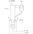
一般的な循環流動炉の構成を図5に示す。該循環流動炉50は、汚泥62等の被処理物を受け入れて燃焼させる縦置円筒状のライザ51と、炉内ガスから流動媒体を分離するサイクロン53と、該サイクロン53で捕集した流動媒体を落下させるダウンカマー54と、該流動媒体を堆積させて炉内未燃ガスのサイクロン53への吹き抜けを防止するシールポット55と、該シールポット55の流動媒体を前記ライザ51に返送する流動媒体戻し管56とから構成される。
Conventionally, circulating fluidized furnaces have been widely used as facilities for burning industrial waste, municipal waste, sewage sludge, and the like. Circulating fluidized furnaces can be combusted stably even with fluctuations in the properties of the material to be treated, and fluidized media such as fluidized sand circulate and flow in the furnace and burn in contact with the material to be treated. Since no problem occurs and uniform combustion treatment is possible, it is suitable for an object to be treated having a high water content such as sewage sludge.
FIG. 5 shows the configuration of a general circulating flow furnace. The circulating fluidized
ライザ51内に投入された被処理物は、ライザ下部より導入される一次空気60により流動しながら流動媒体と混合されて流動層57を形成し、該流動層57にて乾燥、燃焼してガス化する。ガス化により発生した炉内ガスはフリーボード58に導かれ、二次空気61の導入により炉内ガス中の未燃分を完全燃焼し、サイクロン53にて流動媒体と分離され排出される。一方、前記流動媒体はシールポット55を介して前記ライザ51に返送される。かかる構成は例えば特許文献1(特開2001−235128号公報)等に開示されている。
循環流動炉において、炉の安定運転を行なうには流動媒体の炉内循環が円滑に行なわれることが重要である。小型の循環流動炉の場合には流動媒体の制御が容易であるが、炉のスケールアップが求められる場合、ライザが大きくなるにつれてライザ内の速度差が増加し、ライザ内の撹拌効果の減少を招く惧れがある。また、ライザが大きくなるにつれ、炉壁より噴出する二次空気がライザ中心部まで到達し難くなり、ライザ中心部の酸素不足、及び撹拌不足によるガス混合性の悪化を招く惧れもある。
An object to be processed put into the riser 51 is mixed with a fluidized medium while flowing by the
In a circulating fluidized furnace, it is important that the fluid medium be smoothly circulated in the furnace for stable operation of the furnace. In the case of a small circulating fluidized furnace, control of the fluidized medium is easy, but when the scale up of the furnace is required, the speed difference in the riser increases as the riser becomes larger, and the stirring effect in the riser is reduced. There is a fear. Further, as the riser becomes larger, it becomes difficult for the secondary air ejected from the furnace wall to reach the center of the riser, which may lead to deterioration of gas mixing properties due to insufficient oxygen in the center of the riser and insufficient stirring.
そこで、特許文献2(特開2001−235129号公報)では、二次空気噴出ノズルの上方に、耐熱部材で構成された多孔状筒体ノズルを少なくとも炉中心域まで挿設し、該多孔状筒体ノズルから前記フリーボード内に加熱された高速ガスを噴出することによりフリーボード内の排ガスを撹拌混合させる技術を提案している。
これにより、フリーボード内の排ガスの撹拌混合が促進され、CO等の未燃分を減少させ、流動媒体の円滑な循環を可能としている。
しかし、フリーボード内は、二次空気及び増大する炉内ガスにより空塔速度が約4〜6m/sと非常に高速で排ガスが循環しており、かつこの排ガス中には流動媒体、飛灰等の粒子が多く含まれるため、炉内に突出させて設けた多孔状筒体ノズルは摩耗が激しく、長期使用が困難であり、メンテナンスの手間やランニングコストの高騰化が懸念される。
Therefore, in Patent Document 2 (Japanese Patent Laid-Open No. 2001-235129), a porous cylindrical nozzle composed of a heat-resistant member is inserted above the secondary air ejection nozzle to at least the furnace center region, and the porous cylinder is inserted. A technique for stirring and mixing exhaust gas in a free board by ejecting heated high-speed gas from the body nozzle into the free board has been proposed.
Thereby, stirring and mixing of the exhaust gas in the free board is promoted, unburned components such as CO are reduced, and the fluid medium can be smoothly circulated.
However, in the free board, the exhaust gas circulates at a very high speed of about 4 to 6 m / s due to the secondary air and the increasing in-furnace gas. Therefore, the porous cylindrical nozzle provided to protrude into the furnace is very worn and difficult to use for a long period of time.
一方、流動層及びフリーボードでの燃焼効率の向上を図った循環流動炉が特許文献3(特開2000−154911号公報)に開示されている。図6に示すように、この循環流動炉50’は、ライザ51の炉底部に形成された流動層とフリーボードの境界部に絞り部64を形成し、絞り部付近に二次空気噴出ノズル59を設け、斜め上方に二次空気60が噴出する構成としている。これにより、流動層の流動媒体がフリーボードに吹き上げられることがなく燃焼時間を長く確保することができ、かつ絞り部でガス流速が速められることにより流動媒体の循環を円滑に行なうことができる。
On the other hand, Patent Document 3 (Japanese Patent Laid-Open No. 2000-154911) discloses a circulating fluidized furnace that improves combustion efficiency in a fluidized bed and a free board. As shown in FIG. 6, the circulating fluidized
しかしながら、循環流動炉は飛灰、流動媒体等の粒体を含む炉内ガスが、空塔速度約4〜6m/sの高速で循環しているため、前記特許文献3のように炉内側に突出した絞り部を形成すると、該絞り部が摩耗してしまい炉の耐久性に問題が残る。また、一般に流動層の温度はフリーボードよりも低いため、炉内ガスの膨張差により流動層側の方が空塔速度が低いが、絞り部より下方を拡径しているためさらに流動層付近の空塔速度が低下し、ライザ底部に溜まった流動媒体がフリーボードに飛散し難くなる。これによりフリーボードとサイクロンとの間で流動媒体が循環してしまう惧れがあり、高温の流動媒体が流動層に到達せず流動層の温度が低下してしまうという問題を有している。
従って、本発明は上記従来技術の問題点に鑑み、二次空気の適正な吹き込みにより炉内ガスに含まれる未燃分を低減するとともに脱硫効率を向上させ、さらに流動媒体の円滑な循環を図り、炉の安定運転を可能とする循環流動炉を提供することを目的とする。
However, in the circulating fluidized furnace, the gas in the furnace containing particles such as fly ash and fluidized medium is circulated at a high speed of about 4 to 6 m / s in the superficial velocity. If the protruding throttle part is formed, the throttle part is worn away, and there remains a problem in durability of the furnace. Also, since the temperature of the fluidized bed is generally lower than that of the freeboard, the superficial velocity is lower on the fluidized bed side due to the difference in expansion of the gas in the furnace, but since the diameter is expanded below the constricted part, it is further near the fluidized bed. The superficial velocity of the liquid is reduced, and the fluid medium accumulated at the bottom of the riser is less likely to be scattered on the free board. As a result, the fluidized medium may circulate between the free board and the cyclone, and there is a problem that the temperature of the fluidized bed decreases because the high-temperature fluidized medium does not reach the fluidized bed.
Therefore, in view of the above-mentioned problems of the prior art, the present invention reduces the unburned content contained in the furnace gas by appropriately blowing the secondary air, improves the desulfurization efficiency, and further facilitates smooth circulation of the fluid medium. An object of the present invention is to provide a circulating fluidized furnace that enables stable operation of the furnace.
そこで、本発明はかかる課題を解決するために、
炉本体底部から導入される一次空気により被処理物を流動媒体と混合流動させながら燃焼する流動層が炉底に形成されるとともに、該流動層の上方に位置する二次空気導入口から導入される二次空気により、前記流動媒体を循環させながら炉内ガス中の未燃分を燃焼するフリーボードが前記流動層の上方に形成された循環流動炉において、
前記二次空気導入口の上方位置から下方へ向けて縮径するテーパ状の絞り部を設け、前記二次空気導入口高さの炉径を前記絞り部上方の炉径より小とするとともに、炉本体下方空間を炉本体上方空間より小とし、炉本体下方の空塔速度を上昇させることを特徴とする。
Therefore, in order to solve this problem, the present invention provides:
A fluidized bed is formed at the bottom of the furnace while the material to be treated is mixed and fluidized with the fluidized medium by the primary air introduced from the bottom of the furnace body, and introduced from the secondary air inlet located above the fluidized bed. In the circulating fluidized furnace in which a free board for burning unburned components in the gas in the furnace while circulating the fluid medium is formed above the fluidized bed by secondary air.
Provided with a tapered throttle portion that decreases in diameter from the upper position of the secondary air inlet toward the lower side, and makes the furnace diameter of the secondary air inlet height smaller than the furnace diameter above the throttle portion, The space below the furnace body is smaller than the space above the furnace body, and the superficial velocity below the furnace body is increased.
本発明では、炉本体下部に絞り部を設け、該絞り部で縮径された位置に二次空気導入口を設けているため、二次空気を炉本体の中心部に近い位置から供給することができる。その結果、絞りを設けない場合に比べて二次空気は炉本体中心部、若しくは該中心部近くまで到達することができ、炉をスケールアップした場合にも炉の中心に酸素欠乏域が形成されることが殆どなく、未燃ガスの燃焼が促進される。また、炉内ガスの撹拌効果が増大されるため、燃焼、脱硫が促進され、CO等の未燃分の低減や脱硫率増加が可能となり、またフリーボードでの燃焼効率が向上するためダイオキシン類等の発生抑制にもつながる。
また本発明では、絞り部より下方空間をその上方空間より小としているため、炉本体下方の空塔速度を上昇させることができ、流動層の流動媒体及び脱硫剤を活発に流動させることができる。その結果、循環量増加による炉内温度均一化、炉内撹拌活発化によるCO等未燃分の低減、脱硫率の増加が達成できる。
In the present invention, the throttle part is provided at the lower part of the furnace body, and the secondary air inlet is provided at the position reduced in diameter by the throttle part, so the secondary air is supplied from a position close to the center part of the furnace body. Can do. As a result, the secondary air can reach the center of the furnace body or close to the center as compared with the case where no restriction is provided, and even when the furnace is scaled up, an oxygen-depleted region is formed at the center of the furnace. The combustion of unburned gas is promoted. In addition, since the stirring effect of the gas in the furnace is increased, combustion and desulfurization are promoted, and unburned components such as CO can be reduced and the desulfurization rate can be increased. It also leads to suppression of the occurrence of such.
In the present invention, since the space below the throttle portion is smaller than the space above, the superficial velocity below the furnace body can be increased, and the fluidized medium and desulfurizing agent in the fluidized bed can be actively flowed. . As a result, the furnace temperature can be made uniform by increasing the circulation rate, the unburned content such as CO can be reduced, and the desulfurization rate can be increased by increasing the stirring in the furnace.
さらに、汚泥等のように含水率が高い被処理物が処理対象である場合、供給量変動で多量の被処理物が供給された際に、従来の循環流動炉では流動層の温度が低下し、助燃料増加等の対処が遅れた場合には運転停止に陥っていたが、本発明では炉下部で水分蒸発が生じて空塔速度が増加し、循環量が増加する結果、高温の流動媒体が流動層に供給されるため安定した運転を続行することができる。特に本発明のように絞り部を設けた場合には空塔速度がより増加するため、運転安定性が向上する。
また、本発明では絞り部をテーパ状にしているため、炉内ガスの影響による摩耗を最小限に抑えることができ、炉の耐久性向上を図ることができる。
Furthermore, when a material to be treated with a high moisture content such as sludge is the object to be treated, when a large amount of material to be treated is supplied due to fluctuations in the supply amount, the temperature of the fluidized bed decreases in the conventional circulating fluidized furnace. However, in the present invention, water vaporization occurred in the lower part of the furnace, the superficial velocity increased, and the circulation rate increased, resulting in a high temperature fluid medium. Is supplied to the fluidized bed, so that stable operation can be continued. In particular, when the throttle part is provided as in the present invention, the superficial velocity is further increased, and thus the operational stability is improved.
In the present invention, since the throttle portion is tapered, wear due to the influence of the gas in the furnace can be minimized, and the durability of the furnace can be improved.
また、前記流動層底部を基準とした炉高をHとした場合、前記絞り部の縮径始端高さHTがH/6<HT<H/3の範囲内となり、かつ前記絞り部上方の炉本体断面積をAとした場合、炉本体底部断面積A0がA/4<A0<3A/4となるように前記絞り部を形成したことを特徴とする。
これにより、炉高及び炉径に応じて最適な絞り部を形成することができる。即ち、絞り部の高さは流動媒体を吹き飛ばす助走区間の役割を有するため、炉高が大きいほど長い区間が必要と考えられる。従って、上記したように炉高を基準とし、前記範囲内に設定することにより、炉本体がスケールアップした場合においても絞り部を適正化することができる。
同様に、炉本体上部断面積を基準として炉本体底部断面積を前記範囲内に設定することにより、安定した空塔速度を維持でき、円滑な炉の運転が可能となる。尚、炉本体底部面積は小さくするほど空塔速度が増加して流動媒体は飛びやすくなるが、小さすぎると流動媒体が滞留する容積を確保できず燃焼が不十分となるため、上記範囲内とすることが好ましく、さらに好適には前記炉本体底部面積A0=A/2程度が良い。
Also, the case of a fluidized bed bottom furnace height relative to the set to H, condensation径始end height H T of the diaphragm portion is in the range of H / 6 <H T <H / 3, and the narrowed portion upward When the furnace main body cross-sectional area is A, the throttle section is formed such that the furnace main body cross-sectional area A 0 satisfies A / 4 <A 0 <3A / 4.
Thereby, an optimal throttle part can be formed according to the furnace height and the furnace diameter. That is, since the height of the throttle portion has a role of a running section that blows away the fluid medium, it is considered that a longer section is necessary as the furnace height is larger. Therefore, by setting the furnace height as a reference within the above range as described above, the throttle part can be optimized even when the furnace body is scaled up.
Similarly, by setting the furnace body bottom cross-sectional area within the above range on the basis of the furnace main body cross-sectional area, a stable superficial velocity can be maintained, and smooth furnace operation becomes possible. Note that the smaller the bottom area of the furnace body, the higher the superficial velocity and the more easily the fluid medium will fly, but if it is too small, the volume in which the fluid medium stays cannot be secured and the combustion becomes insufficient. Preferably, the furnace main body bottom area A 0 = A / 2 is preferable.
また、前記二次空気の噴出し流速が、約30m/s〜80m/sとなるように設定したことを特徴とする。前記二次空気の噴出し流速を前記範囲内に設定することにより、より効果的に二次空気の貫通距離を長くすることができる。二次空気貫通距離は空気の運動量に関係しており、さらに循環流動炉に供給する二次空気量は決まっているため、二次空気口径が大きすぎると噴出し流速が不足し、噴出し流速を大きくし過ぎると二次空気口径が小さくなり、ともに運動量が低下して二次空気貫通距離が短くなるためである。さらに、噴出し流速の上限を80m/sとすることで、二次空気導入口の圧力損失が減少し、ランニングコスト低減につながる。
さらに、前記二次空気導入口が同水平面上に複数設置された一段配置とすることが好ましく、これにより二次空気導入口数が減少し、その結果、二次空気の貫通距離が増加し、炉本体の中心又は中心近くまで空気を送ることができる。また、前記絞り部の縮径終端高さが前記炉本体の壁面に設置された助燃バーナより上方であることが好適である。
Further, the secondary air ejection flow rate is set to be about 30 m / s to 80 m / s. By setting the ejection speed of the secondary air within the above range, the penetration distance of the secondary air can be increased more effectively. The secondary air penetration distance is related to the momentum of the air, and the amount of secondary air supplied to the circulating fluidizing furnace is fixed, so if the secondary air diameter is too large, the jet flow velocity will be insufficient and the jet flow velocity will be This is because if the air diameter is increased too much, the secondary air diameter becomes small, and the momentum is decreased to shorten the secondary air penetration distance. Furthermore, by setting the upper limit of the jet flow velocity to 80 m / s, the pressure loss at the secondary air inlet is reduced, leading to a reduction in running cost.
Further, it is preferable that a plurality of the secondary air inlets are arranged in a single stage on the same horizontal plane, thereby reducing the number of secondary air inlets, resulting in an increased secondary air penetration distance, Air can be sent to or near the center of the body. In addition, it is preferable that the reduced diameter end height of the throttle portion is above the auxiliary burner installed on the wall surface of the furnace body.
以上記載のごとく本発明によれば、絞り部で縮径された位置に設けた二次空気導入口より二次空気を噴出させる構成としているため、二次空気を炉本体中心部、若しくは該中心部近くまで到達させることができ、炉をスケールアップした場合にも炉の中心に酸素欠乏域が形成されることが殆どなく、未燃ガスの燃焼が促進される。また、炉内ガスの撹拌効果が増大されるため、燃焼、脱硫が促進され、CO等の未燃分の低減や脱硫率増加が可能となり、またフリーボードでの燃焼効率が向上するためダイオキシン類等の発生抑制にもつながる。さらに本発明では絞り部をテーパ状にしているため、炉内ガスの影響による摩耗を最小限に抑えることができ、炉の耐久性を向上させることができる。 As described above, according to the present invention, since the secondary air is ejected from the secondary air inlet provided at the position where the diameter is reduced by the throttle portion, the secondary air is supplied to the center of the furnace body or the center. When the furnace is scaled up, an oxygen-deficient zone is hardly formed at the center of the furnace, and combustion of unburned gas is promoted. In addition, since the stirring effect of the gas in the furnace is increased, combustion and desulfurization are promoted, and unburned components such as CO can be reduced and the desulfurization rate can be increased. It also leads to suppression of the occurrence of such. Furthermore, in the present invention, since the throttle portion is tapered, wear due to the influence of the gas in the furnace can be minimized, and the durability of the furnace can be improved.
また本発明では、絞り部より下方空間をその上方空間より小としているため、流動媒体の循環量増加による炉内温度均一化、炉内撹拌活発化によるCO等未燃分の低減、脱硫率の増加が達成できる。
さらに、前記絞り部始端高さ、炉本体底部断面積を、夫々炉高、炉本体断面積を基準として設定しているため、炉本体をスケールアップした際にも常に適正化された絞り部を形成することが可能である。
Further, in the present invention, the space below the throttle portion is made smaller than the space above it, so that the temperature inside the furnace is made uniform by increasing the circulation amount of the fluidized medium, the unburned content such as CO is reduced by increasing the stirring in the furnace, and the desulfurization rate is increased. An increase can be achieved.
Furthermore, since the starting height of the throttle part and the cross-sectional area of the bottom of the furnace body are set based on the furnace height and the cross-sectional area of the furnace body, respectively, the throttle part that is always optimized even when the furnace body is scaled up. It is possible to form.
以下、図面を参照して本発明の好適な実施例を例示的に詳しく説明する。但しこの実施例に記載されている構成部品の寸法、材質、形状、その相対的配置等は特に特定的な記載がない限りは、この発明の範囲をそれに限定する趣旨ではなく、単なる説明例に過ぎない。
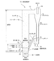
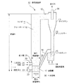
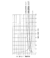
図1は本発明の実施例1に係る循環流動炉の概略断面図、図2は図1の循環流動炉の絞り部を説明する図、図3は本発明の実施例2に係る循環流動炉の概略断面図、図4は二次空気噴出し流速と貫通距離の関係を示すグラフである。
Hereinafter, exemplary embodiments of the present invention will be described in detail with reference to the drawings. However, the dimensions, materials, shapes, relative arrangements, and the like of the components described in this embodiment are not intended to limit the scope of the present invention unless otherwise specified, but are merely illustrative examples. Not too much.
1 is a schematic cross-sectional view of a circulating fluidized furnace according to Embodiment 1 of the present invention, FIG. 2 is a diagram illustrating a throttle section of the circulating fluidized furnace of FIG. 1, and FIG. 3 is a circulating fluidized furnace according to Embodiment 2 of the present invention. FIG. 4 is a graph showing the relationship between the secondary air jet velocity and the penetration distance.
本実施例における循環流動炉10は、図1に示されるように、縦置円筒形状を有し、汚泥投入口21より投入された汚泥32を乾燥、燃焼、ガス化するライザ11と、該ライザ11の上部に接続される排ガス通路12と、該排ガス通路12を介して導入された排ガスを遠心分離により固気分離するサイクロン13と、該サイクロン13の下方に位置する流動媒体の通路であるダウンカマー14と、炉内未燃ガスのサイクロン13への吹き抜けを防止するシールポット15と、流動媒体戻し管16と、を主要構成とする。
前記ライザ11の下方には一次空気導入口から導入される一次空気30により流動媒体が流動、飛散する流動層17が形成され、該流動層17の上方にはフリーボード18が形成されている。
As shown in FIG. 1, the circulating
Below the riser 11, a fluidized bed 17 in which a fluid medium flows and scatters is formed by
前記流動層17には、前記汚泥投入口21より投入された汚泥32が落下し、ここで汚泥32の乾燥、熱分解が行なわれる。また、該流動層17上方のライザ11壁面には二次空気噴出ノズル20が設けられ、該二次空気噴出ノズル20から噴出する二次空気31により形成された上昇気流に搬送されて、飛散した流動媒体、飛灰、未燃ガスを含む炉内ガスが前記フリーボード18に運ばれる。
該フリーボード18では、炉内ガス中の未燃ガスが前記二次空気20の導入により完全燃焼される。飛灰及び流動媒体を含む炉内ガスは、排ガス通路12を経てサイクロン13に導入され、該サイクロン13にて排ガス中の流動媒体を捕集し、ダウンカマー14を介してシールポット15に送給される。一方、前記流動媒体が分離された排ガスは、排ガス排出口14より後段に設けられた熱回収・排ガス処理設備(不図示)に送給される。
Sludge 32 introduced from the
In the free board 18, the unburned gas in the furnace gas is completely burned by the introduction of the
さらに本実施例1では、前記ライザ11の下部に絞り部25を設けた構成としている。該絞り部25は、前記二次空気噴出ノズル20の上方から下方に向けて縮径するテーパ状とする。該絞り部25の縮径始端高さHTは、二次空気噴出ノズル20より上方に位置させ、縮径終端高さは炉底部から二次空気噴出ノズル20の下方位置の何れかの位置とする。
前記絞り部25は、前記二次空気噴出ノズル20の高さ位置の炉径が、該絞り部25より上方のライザ径Dより小となり、かつ絞り部25より下方の空間がこれより上方の空間より小となるように設定する。
このように、前記絞り部25を設け、二次空気噴出ノズル20の高さ位置のライザ径を短縮することにより、二次空気31をライザ中心に近い位置から供給することができ、炉をスケールアップした場合にも炉の中心に酸素欠乏域が形成されることがなく、未燃ガスの燃焼が促進される。また、炉内ガスの撹拌効果が増大されるため、燃焼、脱硫が促進され、CO等の未燃分の低減や脱硫率増加が可能となり、さらにフリーボード18での燃焼効率が向上するためダイオキシン類等の発生抑制にもつながる。
Further, in the first embodiment, a configuration is provided in which a
In the
Thus, by providing the
また、本実施例では絞り部25をテーパ状に形成しているため、炉内ガスによる摩耗を防止でき、炉の耐久性を向上させることができる。
さらに本実施例では、絞り部25より下方空間を、該絞り部25の上方空間より小としているため、ライザ下方の空塔速度を上昇させることができ、流動層17の流動媒体及び脱硫剤を活発に流動させることができる。その結果、循環量増加による炉内温度均一化、炉内撹拌活発化によるCO等未燃分の低減、脱硫率の増加が達成できる。また、処理対象が含水率の高い汚泥である場合には、さらにライザ下部の空塔速度を上昇させることができ、運転の安定性が向上する。
Further, in the present embodiment, since the
Furthermore, in this embodiment, since the space below the
また、本実施例において、前記流動層17の底部を基準とした炉高をHとした場合、前記絞り部25の縮径始端高さHTがH/6<HT<H/3の範囲内となり、かつ前記絞り部25より上方のライザ断面積をAとした場合、該ライザ底部断面積A0がA/4<A0<3A/4、好適にはA0=A/2程度となるように前記絞り部25を形成することが好ましい。
これは、前記絞り部高さHTは流動媒体の砂を飛ばす助走区間の役割を有するため、炉高が高いほど長い区間が必要とされる。従って、絞り部高さHTを炉高Hを基準として設定することにより、絞り部25の適正化が図れる。
Further, in this embodiment, when the furnace height relative to the bottom of the fluidized bed 17 and the H, condensation径始end height H T of the narrowed
This is because the throttle height H T has a role of a run-up section in which the sand of the fluid medium is blown, so that a longer section is required as the furnace height is higher. Accordingly, the throttle portion height H T by setting the Rodaka H as a reference, optimization of the
また、ライザ径Dを基準として絞り部25の縮径角度を設定することにより、ライザの大きさに応じて絞り部25を最適化することができる。
即ち、図2(a)に示すライザ径D1からスケールアップを行い、(b)に示すライザ径D2とした場合、ライザ径に比例して二次空気噴出ノズル20の炉径差d2はd1より大きくなる。このように、ライザ径Dを基準とすることにより、空塔速度を好適に保持しながら、かつ流動層17での滞留時間を十分にとることができる構成とすることができ、炉の大きさに対応した絞り部の適正化が図れる。
In addition, by setting the diameter of the narrowed
That performs a scale-up from the riser diameter D 1 shown in FIG. 2 (a), when the riser diameter D 2 shown in (b), furnace in proportion to the riser diameter secondary
また、本実施例では前記二次空気31の噴出し流速を、約30m/s〜80m/sとなるように設定する。これは、図4に示される二次空気噴出し流速と貫通距離の関係からも明らかなように、噴出し流速が30m/s以下であると、ノズル径が大きくなり二次空気31の到達距離が短くなってしまい、一方噴出し流速が80m/s以上では二次空気31の到達距離は殆ど変化がないにも関わらず、圧力損失が増大し、ブロワ等の機器に高機能性が求められ、コストが増大してしまうためである。
従って、前記二次空気31の噴出し流速を前記範囲内とすることで、効率良い二次空気の供給が達成できる。
In the present embodiment, the flow velocity of the secondary air 31 is set to be about 30 m / s to 80 m / s. As is apparent from the relationship between the secondary air ejection flow velocity and the penetration distance shown in FIG. 4, when the ejection flow velocity is 30 m / s or less, the nozzle diameter increases and the reach distance of the secondary air 31 is increased. On the other hand, when the jet flow velocity is 80 m / s or more, although the reach of the secondary air 31 is almost unchanged, the pressure loss increases, and the blower and other devices are required to have high functionality. This is because the cost increases.
Therefore, the secondary air 31 can be efficiently supplied by setting the flow velocity of the secondary air 31 within the above range.
さらに、前記二次空気噴出ノズル20の配置を、同水平面上に複数設置された一段配置とすることが好ましい。これにより、二次空気噴出ノズル数を低減することができ、二次空気噴出ノズル1本当りの供給空気量が増加する。その結果、二次空気噴出し流速を増大でき、二次空気31の到達距離が伸び、ライザ11の中心若しくは中心付近まで二次空気を送ることができる。
また、図3に示した実施例2のように、前記絞り部25の縮径終端高さを、前記ライザ11の壁面に設置した助燃バーナ22より上方とし、縮径終端より下方を円筒形状としても良い。これにより、含水率が高い汚泥等のように、流動層17内での滞留時間が長い場合においても実施例1よりライザ下方空間を大にすることができるため、汚泥の滞留時間を十分に確保できる。
Furthermore, it is preferable that the secondary air ejection nozzles 20 are arranged in a single stage in which a plurality of secondary air ejection nozzles 20 are installed on the horizontal plane. Thereby, the number of secondary air ejection nozzles can be reduced, and the amount of supply air per secondary air ejection nozzle increases. As a result, the secondary air ejection flow rate can be increased, the reach of the secondary air 31 can be extended, and the secondary air can be sent to the center of the riser 11 or near the center.
Further, as in the second embodiment shown in FIG. 3, the reduced diameter end height of the
本実施例において、ライザ高さ方向の温度分布に基づき絞り部を形成し、炉内ガスの空塔速度がほぼ一定となるように構成しても良い。これにより、流動媒体の循環が円滑に行なわれ、より一層安定した炉の運転が可能となる。 In this embodiment, a constricted portion may be formed based on the temperature distribution in the riser height direction so that the superficial velocity of the in-furnace gas is substantially constant. Thereby, circulation of a fluid medium is performed smoothly and the operation of a more stable furnace is attained.
10 循環流動炉
11 ライザ
13 サイクロン
20 二次空気噴出ノズル
21 汚泥投入口
22 助燃バーナ
25 絞り部
30 一次空気
31 二次空気
DESCRIPTION OF
Claims (5)
前記二次空気導入口の上方位置から下方へ向けて縮径するテーパ状の絞り部を設け、前記二次空気導入口高さの炉径を前記絞り部上方の炉径より小とするとともに、炉本体下方空間を炉本体上方空間より小とし、炉本体下方の空塔速度を上昇させることを特徴とする循環流動炉。 A fluidized bed is formed at the bottom of the furnace while the material to be treated is mixed and fluidized with the fluidized medium by the primary air introduced from the bottom of the furnace body, and introduced from the secondary air inlet located above the fluidized bed. In the circulating fluidized furnace in which a free board for burning unburned components in the gas in the furnace while circulating the fluid medium is formed above the fluidized bed by secondary air.
Provided with a tapered throttle portion that decreases in diameter from the upper position of the secondary air inlet toward the lower side, and makes the furnace diameter of the secondary air inlet height smaller than the furnace diameter above the throttle portion, A circulating fluidizing furnace characterized in that the space below the furnace body is smaller than the space above the furnace body, and the superficial velocity below the furnace body is increased.
Priority Applications (1)
| Application Number | Priority Date | Filing Date | Title |
|---|---|---|---|
| JP2004112130A JP2005299938A (en) | 2004-04-06 | 2004-04-06 | Circulated fluidized furnace |
Applications Claiming Priority (1)
| Application Number | Priority Date | Filing Date | Title |
|---|---|---|---|
| JP2004112130A JP2005299938A (en) | 2004-04-06 | 2004-04-06 | Circulated fluidized furnace |
Publications (1)
| Publication Number | Publication Date |
|---|---|
| JP2005299938A true JP2005299938A (en) | 2005-10-27 |
Family
ID=35331688
Family Applications (1)
| Application Number | Title | Priority Date | Filing Date |
|---|---|---|---|
| JP2004112130A Pending JP2005299938A (en) | 2004-04-06 | 2004-04-06 | Circulated fluidized furnace |
Country Status (1)
| Country | Link |
|---|---|
| JP (1) | JP2005299938A (en) |
Cited By (7)
| Publication number | Priority date | Publication date | Assignee | Title |
|---|---|---|---|---|
| CN100458282C (en) * | 2005-11-03 | 2009-02-04 | 中国石油大学(北京) | Internal mixing combustion device for burning petroleum coke or gasified waste coke |
| JP2012037212A (en) * | 2010-08-12 | 2012-02-23 | Ihi Corp | Oxygen flow combustion device in circulating fluidized bed system |
| JP2013532268A (en) * | 2010-06-02 | 2013-08-15 | イエフペ エネルジ ヌヴェル | Particle separator for chemical looping combustion loops. |
| CN105617953A (en) * | 2016-01-08 | 2016-06-01 | 浙江大学 | Circulating fluidized bed with semi-conical descending section |
| CN109647158A (en) * | 2019-02-28 | 2019-04-19 | 兖矿集团有限公司 | A kind of circulating fluidized bed boiler flue gas desulfurization and denitrification system and its processing method |
| JP2019105415A (en) * | 2017-12-13 | 2019-06-27 | 住友金属鉱山株式会社 | Fluidized roasting furnace, and method for operating fluidized roasting furnace |
| EP2634484B1 (en) | 2010-10-29 | 2022-01-26 | Institute Of Engineering Thermophysics, Chinese Academy Of Sciences | Circulating fluidized bed boiler |
-
2004
- 2004-04-06 JP JP2004112130A patent/JP2005299938A/en active Pending
Cited By (7)
| Publication number | Priority date | Publication date | Assignee | Title |
|---|---|---|---|---|
| CN100458282C (en) * | 2005-11-03 | 2009-02-04 | 中国石油大学(北京) | Internal mixing combustion device for burning petroleum coke or gasified waste coke |
| JP2013532268A (en) * | 2010-06-02 | 2013-08-15 | イエフペ エネルジ ヌヴェル | Particle separator for chemical looping combustion loops. |
| JP2012037212A (en) * | 2010-08-12 | 2012-02-23 | Ihi Corp | Oxygen flow combustion device in circulating fluidized bed system |
| EP2634484B1 (en) | 2010-10-29 | 2022-01-26 | Institute Of Engineering Thermophysics, Chinese Academy Of Sciences | Circulating fluidized bed boiler |
| CN105617953A (en) * | 2016-01-08 | 2016-06-01 | 浙江大学 | Circulating fluidized bed with semi-conical descending section |
| JP2019105415A (en) * | 2017-12-13 | 2019-06-27 | 住友金属鉱山株式会社 | Fluidized roasting furnace, and method for operating fluidized roasting furnace |
| CN109647158A (en) * | 2019-02-28 | 2019-04-19 | 兖矿集团有限公司 | A kind of circulating fluidized bed boiler flue gas desulfurization and denitrification system and its processing method |
Similar Documents
| Publication | Publication Date | Title |
|---|---|---|
| WO1999066264A1 (en) | Operating method of fluidized-bed incinerator and the incinerator | |
| US6709636B1 (en) | Method and apparatus for gasifying fluidized bed | |
| CA2364400C (en) | Fluidized bed incinerator and combustion method in which generation of nox, co and dioxine are suppressed | |
| JP2005299938A (en) | Circulated fluidized furnace | |
| JP5898217B2 (en) | Fluidized bed furnace and waste treatment method using fluidized bed furnace | |
| JP3913229B2 (en) | Circulating fluid furnace | |
| KR101200531B1 (en) | Circulating fluidizing-bed boiler | |
| US5915309A (en) | Fluidized bed incinerator | |
| EP3054214B1 (en) | Method for feeding air to a fluidized bed boiler, a fluidized bed boiler and fuel feeding means for a fluidized bed boiler | |
| JP2005308372A (en) | Fluidized bed furnace | |
| KR100763775B1 (en) | Internal Circulating Fluidized Bed Combustion Furnace for RDF | |
| JP3790418B2 (en) | Operating method of external circulating fluidized bed furnace for waste incinerator with high water content and high volatility such as sewage sludge | |
| JP3973919B2 (en) | High temperature gasifier | |
| TWI848285B (en) | Combustion device, boiler, and combustion method | |
| JP2003294217A (en) | Equipment and method for incineration treatment of treating object containing organic substance | |
| JP2007163132A (en) | Fluidized bed gasification method and apparatus | |
| JP2003042424A (en) | Fluidized bed furnace, and supply method for solid incinerated substance with low specific gravity to the fluidized bed furnace | |
| JP2941785B1 (en) | Operating method of fluidized bed incinerator and its incinerator | |
| KR102794248B1 (en) | Fluidized bed heat recovery unit | |
| JP2005121342A (en) | Operation method of circulating fluidized bed furnace | |
| SK48798A3 (en) | Method and apparatus for controlling the temperature of the bed of a bubbling bed boiler | |
| EP0601584A1 (en) | Waste incinerator and waste incinerating method using same | |
| JP3387989B2 (en) | Fluidized bed furnace | |
| JP2001235129A (en) | Circulating fluidized bed furnace | |
| JP2002098313A (en) | Circulating fluidized bed combustion device |
Legal Events
| Date | Code | Title | Description |
|---|---|---|---|
| A977 | Report on retrieval |
Free format text: JAPANESE INTERMEDIATE CODE: A971007 Effective date: 20060824 |
|
| A131 | Notification of reasons for refusal |
Effective date: 20060908 Free format text: JAPANESE INTERMEDIATE CODE: A131 |
|
| A521 | Written amendment |
Free format text: JAPANESE INTERMEDIATE CODE: A523 Effective date: 20061107 |
|
| A131 | Notification of reasons for refusal |
Effective date: 20070109 Free format text: JAPANESE INTERMEDIATE CODE: A131 |
|
| A521 | Written amendment |
Effective date: 20070312 Free format text: JAPANESE INTERMEDIATE CODE: A523 |
|
| A02 | Decision of refusal |
Free format text: JAPANESE INTERMEDIATE CODE: A02 Effective date: 20070427 |
|
| A521 | Written amendment |
Effective date: 20070627 Free format text: JAPANESE INTERMEDIATE CODE: A523 |
|
| A911 | Transfer of reconsideration by examiner before appeal (zenchi) |
Free format text: JAPANESE INTERMEDIATE CODE: A911 Effective date: 20070703 |
|
| A912 | Removal of reconsideration by examiner before appeal (zenchi) |
Effective date: 20070817 Free format text: JAPANESE INTERMEDIATE CODE: A912 |
|
| A711 | Notification of change in applicant |
Effective date: 20080602 Free format text: JAPANESE INTERMEDIATE CODE: A712 |
|
| A521 | Written amendment |
Free format text: JAPANESE INTERMEDIATE CODE: A523 Effective date: 20080716 |
|
| A521 | Written amendment |
Effective date: 20091201 Free format text: JAPANESE INTERMEDIATE CODE: A523 |