JP2005299519A - Engine speed control device for high pressure washer - Google Patents
Engine speed control device for high pressure washer Download PDFInfo
- Publication number
- JP2005299519A JP2005299519A JP2004117178A JP2004117178A JP2005299519A JP 2005299519 A JP2005299519 A JP 2005299519A JP 2004117178 A JP2004117178 A JP 2004117178A JP 2004117178 A JP2004117178 A JP 2004117178A JP 2005299519 A JP2005299519 A JP 2005299519A
- Authority
- JP
- Japan
- Prior art keywords
- water discharge
- engine
- engine speed
- work
- speed
- Prior art date
- Legal status (The legal status is an assumption and is not a legal conclusion. Google has not performed a legal analysis and makes no representation as to the accuracy of the status listed.)
- Withdrawn
Links
Images


Landscapes
- Cleaning By Liquid Or Steam (AREA)
- Electrical Control Of Air Or Fuel Supplied To Internal-Combustion Engine (AREA)
- Combined Controls Of Internal Combustion Engines (AREA)
Abstract
【課題】 簡素な構成で放水作業の実行と停止に応じてエンジン回転数を制御して作業性を向上(安定)させると共に、燃費を向上させつつ騒音を低減させるようにした高圧洗浄機のエンジン回転数制御装置を提供する。
【解決手段】 エンジンの吸気路に設けられたスロットルバルブの開度θTHを調整するアクチュエータを設け、放水作業が実行されていると判断されるとき(S20)、エンジン回転数NE(目標エンジン回転数NED)を作業時回転数NEDaに上昇させる(S26)一方、放水作業が実行されていないと判断されるとき(S28)、エンジン回転数NEを作業停止時回転数NEDiに下降させる(S32)ように前記アクチュエータの駆動を制御する。
【選択図】 図8
PROBLEM TO BE SOLVED: To improve (stable) workability by controlling the engine speed according to execution and stop of a water discharge operation with a simple configuration, and to improve noise and reduce noise while improving fuel efficiency. A rotational speed control device is provided.
An actuator for adjusting an opening θTH of a throttle valve provided in an intake passage of an engine is provided, and when it is determined that a water discharge operation is being performed (S20), an engine speed NE (target engine speed) NED) is increased to the working speed NEDA (S26). On the other hand, when it is determined that the water discharge work is not performed (S28), the engine speed NE is lowered to the working speed NEDi (S32). To control the driving of the actuator.
[Selection] Figure 8
Description
この発明は、高圧洗浄機のエンジン回転数制御装置に関する。 The present invention relates to an engine speed control device for a high-pressure washing machine.
従来、高圧洗浄機において、搭載されたエンジンでポンプを駆動し、かかるポンプによって加圧された水を放出する技術が知られている。このような高圧洗浄機においては、一般に機械式ガバナによってエンジン回転数の調整をしている。従って、操作者がエンジン回転数の調整を行う場合、機械式ガバナにワイヤを介して取り付けられたレバー(回転数調整レバー)を手動で操作することで行われていた。 2. Description of the Related Art Conventionally, a technology is known in which a pump is driven by a mounted engine and water pressurized by the pump is discharged in a high-pressure washing machine. In such a high pressure washer, the engine speed is generally adjusted by a mechanical governor. Therefore, when the engine speed is adjusted by the operator, the lever (rotational speed adjusting lever) attached to the mechanical governor via a wire is manually operated.
そのため、放水を一時的に停止させることの多い作業などでは、放水作業の停止や再開の都度、エンジン回転数を操作者が調整する必要があって煩瑣であった。その結果、放水作業を停止しているにも関わらず、エンジン回転数が放水作業時の回転数(放水作業停止時より高い回転数)に維持されたままとなることが多く、それに伴って燃費が悪化すると共に、騒音が大きくなるという不具合があった。 Therefore, in work that often stops water discharge temporarily, the operator has to adjust the engine speed every time the water discharge work is stopped or restarted. As a result, despite the fact that the water discharge operation is stopped, the engine speed is often maintained at the rotation speed at the time of the water discharge work (a higher speed than when the water discharge work is stopped). However, there was a problem that the noise became louder.
そこで、例えば、特許文献1に記載される技術にあっては、操作者によってノズルに取り付けられた手元コックが閉じられたとき(操作者が放水作業を停止したとき)、無負荷弁(アンロード弁)が作動して高圧ポンプを無負荷運転(ポンプ無負荷状態)にすると共に、その無負荷弁の弁体の動きに連動してエンジンのガバナレバーを回転させるように構成している。この回転によってガバナレバーに連結されたガバナロッドが押され、さらにガバナロッドに連結されたスロットルレバーが閉方向に回転させられることでスロットルバルブが閉じ、よってエンジン回転数を自動的に低下させるように構成している。 Thus, for example, in the technique described in Patent Document 1, when the hand cock attached to the nozzle is closed by the operator (when the operator stops the water discharge operation), a no-load valve (unloading) And the high pressure pump is put into a no-load operation (pump no-load state), and the governor lever of the engine is rotated in conjunction with the movement of the valve body of the no-load valve. By this rotation, the governor rod connected to the governor lever is pushed, and further, the throttle lever connected to the governor rod is rotated in the closing direction so that the throttle valve is closed, and thus the engine speed is automatically reduced. Yes.
しかしながら、上記特許文献1に記載されるような無負荷弁の変位に応じてガバナレバーを操作する構成では、無負荷弁の弁体の動きに連動するスピンドルを設けると共に、スピンドルとガバナレバーの間にワイヤを引き回す必要があり、構成が複雑であった。 However, in the configuration in which the governor lever is operated in accordance with the displacement of the no-load valve as described in Patent Document 1, a spindle that is linked to the movement of the valve body of the no-load valve is provided, and a wire is provided between the spindle and the governor lever. The configuration was complicated.
従って、この発明の目的は上記した課題を解決することにあり、より簡素な構成で放水作業の実行と停止に応じてエンジン回転数を制御して作業性を向上(安定)させると共に、燃費を向上させつつ騒音を低減させるようにした高圧洗浄機のエンジン回転数制御装置を提供することにある。 Accordingly, an object of the present invention is to solve the above-described problem, and with a simpler configuration, the engine speed is controlled according to the execution and stoppage of the water discharge operation to improve (stabilize) workability and improve fuel efficiency. An object of the present invention is to provide an engine speed control device for a high-pressure washing machine that is improved and reduces noise.
上記の課題を解決するために、請求項1にあっては、搭載されたエンジンでポンプを駆動して加圧しつつ放水部から放水して洗浄する高圧洗浄機のエンジン回転数制御装置において、前記エンジンの吸気路に設けられたスロットルバルブの開度を調整するアクチュエータと、放水作業が実行されているか否かを判断する作業実行判断手段と、前記作業実行判断手段により、前記放水作業が実行されていると判断されるとき、エンジン回転数を作業時回転数に上昇させる一方、前記放水作業が実行されていないと判断されるとき、前記エンジン回転数を作業停止時回転数に下降させるように前記アクチュエータの駆動を制御するエンジン回転数制御手段とを備えるように構成した。 In order to solve the above-mentioned problem, in claim 1, in the engine rotation speed control device of the high-pressure washing machine that discharges water from the water discharge portion and cleans it while driving and pressurizing the pump with the mounted engine, The water discharge operation is executed by an actuator that adjusts the opening of a throttle valve provided in the intake passage of the engine, a work execution determination unit that determines whether or not a water discharge operation is being performed, and the work execution determination unit. When it is determined that the engine is rotating, the engine speed is increased to the working speed, and when it is determined that the water discharge operation is not being performed, the engine speed is decreased to the operating speed. Engine rotational speed control means for controlling the drive of the actuator is provided.
また、請求項2にあっては、さらに、前記エンジンの回転数を検出するエンジン回転数検出手段と、前記スロットルバルブの開度を検出するスロットル開度検出手段と、前記検出されたエンジン回転数とスロットル開度に基づいて前記エンジンの出力がしきい値以上か否かを推定するエンジン出力推定手段とを備えると共に、前記作業実行判断手段は、前記エンジンの出力が前記しきい値以上と推定されたとき、前記放水作業が実行されていると判断するように構成した。 Further, in the present invention, the engine speed detecting means for detecting the engine speed, the throttle opening detecting means for detecting the throttle valve opening, and the detected engine speed. And engine output estimating means for estimating whether the engine output is equal to or greater than a threshold value based on the throttle opening, and the work execution determining means estimates that the engine output is equal to or greater than the threshold value. When it was done, it comprised so that it might be judged that the said water discharge work was performed.
また、請求項3にあっては、前記作業実行判断手段は、所定時間以上継続して前記エンジンの出力が前記しきい値以上と推定されたとき、前記放水作業が実行されていると判断するように構成した。 According to a third aspect of the present invention, the work execution determination means determines that the water discharge operation is being performed when the engine output is estimated to be equal to or greater than the threshold value for a predetermined time or longer. It was configured as follows.
また、請求項4にあっては、さらに、前記放水部に取り付けられて操作者によって操作可能な放水実行手段と、前記操作者によって前記放水実行手段が操作されたとき、放水実行信号を出力する放水実行信号出力手段とを備えると共に、前記作業実行判断手段は、前記放水実行信号出力手段から前記放水実行信号が入力されたとき、前記放水作業が実行されていると判断するように構成した。 Moreover, in Claim 4, when the water discharge execution means attached to the water discharge section and operable by an operator is operated by the operator, the water discharge execution signal is output. The water discharge execution signal output means, and the work execution determination means is configured to determine that the water discharge work is being executed when the water discharge execution signal is input from the water discharge execution signal output means.
また、請求項5にあっては、さらに、前記放水部に取り付けられて操作者によって操作可能なエンジン回転数変更指示入力手段を備えると共に、前記エンジン回転数制御手段は、前記エンジン回転数変更指示入力手段からの指示が入力されたとき、前記作業時回転数を変更するように構成した。 Further, according to claim 5, the engine speed change instruction input means that is attached to the water discharge unit and can be operated by an operator is provided, and the engine speed control means includes the engine speed change instruction. When an instruction from the input means is input, the rotation speed during operation is changed.
請求項1に係る高圧洗浄機のエンジン回転数制御装置においては、エンジンの吸気路に設けられたスロットルバルブの開度を調整するアクチュエータを備えると共に、放水作業が実行されているか否かを判断し、放水作業が実行されていると判断されるとき、エンジン回転数を作業時回転数に上昇させる一方、実行されていないと判断されるとき、エンジン回転数を作業停止時回転数に下降させるようにアクチュエータの駆動を制御する如く構成したので、操作者によるエンジン回転数の調整作業を不要とすることができる、即ち、自動的に放水作業の実行と停止に応じたエンジン回転数の制御を行うことができ、よって作業性を向上(安定)させることができる。さらには、作業停止時にエンジン回転数を下降させることで、燃費を向上させつつ騒音を低減させることができる。 In the engine speed control device for a high-pressure washing machine according to claim 1, an actuator for adjusting the opening degree of a throttle valve provided in the intake passage of the engine is provided, and it is determined whether or not a water discharge operation is being performed. When it is determined that the water discharge work is being performed, the engine speed is increased to the work speed, while when it is determined not to be performed, the engine speed is decreased to the work stop speed. Therefore, the operation of adjusting the engine speed by the operator can be made unnecessary, that is, the engine speed is automatically controlled according to the execution and stoppage of the water discharge operation. Therefore, workability can be improved (stable). Furthermore, by reducing the engine speed when the work is stopped, noise can be reduced while improving fuel efficiency.
また、請求項2にあっては、エンジンの回転数とスロットルバルブの開度を検出し、検出されたエンジン回転数とスロットル開度に基づいてエンジンの出力がしきい値以上か否かを推定し、エンジン出力がしきい値以上のとき、放水作業が実行されていると判断するように構成したので、放水作業が実行されているか否かをより正確に判断することができ、よって請求項1で述べた効果をより一層得ることができる。 Further, according to the present invention, the engine speed and the throttle valve opening are detected, and it is estimated whether or not the engine output is equal to or greater than a threshold value based on the detected engine speed and the throttle opening. However, when the engine output is equal to or greater than the threshold value, it is determined that the water discharge work is being performed. Therefore, it is possible to more accurately determine whether the water discharge work is being performed, and thus the claim. The effect described in 1 can be further obtained.
また、請求項3にあっては、所定時間以上継続して前記エンジンの出力が前記しきい値以上と推定されたとき、放水作業が実行されていると判断するように構成したので、上記した効果に加え、エンジンに作用する負荷を精度良く判断することができ(エンジン出力の一時的な変動(燃料溜りなどに起因する偶発的な変動)を負荷変動と誤って判断することがなく)、よって放水作業の実行と停止に応じたエンジン回転数の切り換えをより的確に行うことができる。さらには、エンジン回転数が頻繁に切り替わる(ハンチングが生じる)のを防止することができる。 Further, in the third aspect of the present invention, when the engine output is estimated to be equal to or greater than the threshold value continuously for a predetermined time or longer, it is determined that the water discharge operation is being performed. In addition to the effect, it is possible to accurately determine the load acting on the engine (temporary fluctuations in engine output (accidental fluctuations due to fuel accumulation, etc.) are not mistakenly determined as load fluctuations) Therefore, the engine speed can be switched more accurately according to the execution and stoppage of the water discharge operation. Furthermore, it is possible to prevent the engine speed from frequently switching (causing hunting).
また、請求項4にあっては、放水部に取り付けられて操作者によって操作可能な放水実行手段と、操作者によって放水実行手段が操作されたとき、放水実行信号を出力する放水実行信号出力手段とを備えると共に、放水実行信号出力手段から放水実行信号が入力されたとき、放水作業が実行されていると判断するように構成したので、請求項1で述べた効果を簡素な構成で得ることができる。 Further, in claim 4, a water discharge execution means attached to the water discharge section and operable by an operator, and a water discharge execution signal output means for outputting a water discharge execution signal when the water discharge execution means is operated by the operator. In addition, when the water discharge execution signal is input from the water discharge execution signal output means, it is determined that the water discharge work is being executed. Therefore, the effect described in claim 1 can be obtained with a simple structure. Can do.
また、請求項5にあっては、放水部に取り付けられて操作者によって操作可能なエンジン回転数変更指示入力手段を備えると共に、エンジン回転数変更指示入力手段からの指示が入力されたとき、前記作業時回転数を変更するように構成したので、上記した効果に加え、操作者が放水作業を行いながら作業時回転数を変更(所望の水量(水圧)に変更)することができ、よって作業性を一層向上させることができる。さらには、スロットル開度を上記の如くアクチュエータによって調整するようにしたことから、エンジン回転数をエンジン回転数変更指示入力手段を介して入力された作業時回転数に精度よく一致させることができ、よって機械式ガバナを用いた従来例に比して作業時回転数(水量(水圧))を微調整することが可能となって作業性をより一層向上させることができる。 Further, in claim 5, the engine speed change instruction input means that is attached to the water discharge unit and can be operated by an operator is provided, and when an instruction from the engine speed change instruction input means is input, In addition to the effects described above, the operator can change the rotation speed at work (change it to the desired amount of water (water pressure)) while performing the water discharge work. Property can be further improved. Furthermore, since the throttle opening is adjusted by the actuator as described above, the engine speed can be made to coincide with the working speed input via the engine speed change instruction input means with high accuracy. Therefore, it is possible to finely adjust the working rotation speed (water amount (water pressure)) as compared with the conventional example using the mechanical governor, and the workability can be further improved.
以下、添付図面に即してこの発明に係る高圧洗浄機のエンジン回転数制御装置を実施するための最良の形態について説明する。 The best mode for carrying out an engine speed control device for a high-pressure washing machine according to the present invention will be described below with reference to the accompanying drawings.
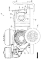
図1は、この実施の形態に係る高圧洗浄機用エンジン回転数制御装置が搭載される高圧洗浄機の本体の平面図である。また、図2は、図1に示す高圧洗浄機の本体の左側面図である。 FIG. 1 is a plan view of a main body of a high pressure washer equipped with an engine speed control device for a high pressure washer according to this embodiment. FIG. 2 is a left side view of the main body of the high pressure washer shown in FIG.
図1および図2において、符号10は高圧洗浄機を示す。高圧洗浄機10は、フレーム12と、フレーム12に取り付けられた把手14と、フレーム12の左右(図1,2において矢印の向きを進行方向とした場合の左右)に取り付けられた車輪16R,16Lとを備える。
1 and 2,
高圧洗浄機10のフレーム12の先端付近にエンジン18(内燃機関。後述)、後端付近にポンプ20が搭載される。尚、エンジン18は、リコイルスタータ22を備え、操作者によって手動で始動される。
An engine 18 (an internal combustion engine, which will be described later) is mounted near the front end of the
図1に示すように、エンジン18のクランク軸18Sは、エンジン側プーリ24に巻き掛けられたベルト26を介し、ポンプ20の駆動軸20Sに取り付けられたポンプ側プーリ28と接続される。従って、ポンプ20は、ベルト26によってエンジン18の回転出力が駆動軸20Sに伝達されて駆動される。
As shown in FIG. 1, the
また、ポンプ20には給水管30が接続される。給水管30の一端はポンプ20の吸水口32に接続されると共に、その他端は水道などの水源(図示せず)に接続される。従って、給水管30はポンプ20に供給される水の流路となる。
A
ポンプ20の吐出口(図1,2で見えず)には、ポンプで加圧された水の流路である放水管34の一端が接続される。また、放水管34の他端には高圧ホース36が接続され、高圧ホース36の先端には洗浄ガン(放水部)(図1,2で図示せず)が取り付けられる。
One end of a
放水管34の途中には、調圧機能を備えたアンロード弁40を介して還流管42の一端が接続され、その他端は給水管30の途中に接続される。即ち、還流管42は放水管34から分岐されて給水管30に接続されている。
One end of the
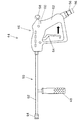
図3は、高圧洗浄機の洗浄ガン(放水部)の左側面図である。 FIG. 3 is a left side view of a cleaning gun (water discharge unit) of the high pressure washer.
図3において、符号44は洗浄ガンを示す。洗浄ガン44は、把持部46、フォアグリップ48および水が放出される放出部50からなる。把持部46は、操作者によって把持されるグリップ52を備えると共に、グリップ52に対して移動自在なトリガ54を備える。さらに、グリップ52の端部(底面)には高圧ホース接続口56が設けられ、前記した高圧ホース36の先端と接続される。また、把持部46の適宜位置、具体的には、グリップ52の重力方向において上部付近に、エンジン18の回転数(アイドリング回転数よりも高く設定された作業時回転数)を変更(調整)するボリューム58(エンジン回転数変更指示入力手段)が設けられる。ボリューム58の付近にはボリュームセンサ60が配置され、操作者によってボリューム58を介して入力されたエンジン回転数(作業時回転数)に応じた信号を出力する。
In FIG. 3,
また、放出部50は、内部に加圧された水を圧送する流路を有したバレル62を備え、その一端は、把持部46に接続されると共に、他端には水が噴出(放出)されるノズル64が取り付けられる。さらに、バレル62の適宜位置には前記したフォアグリップ48が下向きに取り付けられる。
The
ここで、洗浄ガン44の動作について簡単に説明すると、洗浄ガン44の内部には前記した高圧ホース接続口56とノズル64を連通する流路が設けられると共に、前記流路内にはトリガ54の動作と機械的に連動して前記流路を開閉するニードル弁(図示せず)が設けられる。前記ニードル弁は、操作者によってトリガ54が図3の矢印方向に操作されたときに開弁して前記流路と外部(大気)を連通させる一方、トリガ54が操作されていないときに閉弁して前記流路を密閉(封止)させる。
Here, the operation of the cleaning
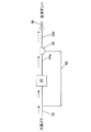
次いで、図4および図5を参照して放水作業時および放水作業停止時の水の流れについて説明する。図4は、放水作業時の水の流れを示す模式図であり、図5は作業停止時のそれである。 Next, with reference to FIG. 4 and FIG. 5, the flow of water at the time of water discharge work and when the water discharge work is stopped will be described. FIG. 4 is a schematic diagram showing the flow of water during the water discharge operation, and FIG. 5 is that when the operation is stopped.
放水作業を行うために操作者によって洗浄ガンのトリガ54が操作されると、水は、図4に示す如く、給水管30、ポンプ20、第1の放水管34a、アンロード弁40、第2の放水管34bおよび高圧ホース36を介して洗浄ガンへ圧送され、洗浄ガンのノズル64から放水(噴射)される。即ち、ポンプ18に負荷が作用する状態(ポンプ負荷状態)となる。尚、ポンプ20からアンロード弁40までの放水管34を第1の放水管34aとし、アンロード弁40から高圧ホース36との接続位置までのそれを第2の放水管34bとした。
When the operator operates the
一方、放水作業の停止時(即ち、操作者によって洗浄ガンのトリガ54が操作されていないとき)は、前述の如く洗浄ガン内のニードル弁によって流路が密閉され、よって流路内の水圧(流路からアンロード弁40までの間にある水の圧力)が急激に上昇する。この水圧の上昇により、アンロード弁40が動作し(具体的には、アンロード弁内にある逆止弁(図示せず)が閉じ、アンロード弁内にあってリリーフ弁に連結されたピストン(図示せず)が押し上げられ)、第1の放水管34aと還流管42を連通させると共に、第1の放水管34aと第2の放水管34bを連通させる流路を閉じる。これにより、水は、図5に示す如く、給水管30、ポンプ20、第1の放水管34a、アンロード弁40および還流管42を循環させられる。即ち、ポンプ20に作用する負荷がほとんどない状態(ポンプ無負荷状態)となる。
On the other hand, when the water discharge operation is stopped (that is, when the
図6は、エンジン18の説明断面図である。
FIG. 6 is an explanatory sectional view of the
エンジン18は、1個の気筒(シリンダ)70を備え、その内部にピストン72が往復動自在に収容される。ピストン72の頭部と気筒壁面の間には燃焼室74が形成されると共に、気筒壁面には吸気バルブ76と排気バルブ78が配置され、燃焼室74と吸気路80あるいは排気路82の間を開閉する。尚、エンジン18は、具体的には空冷4サイクルの単気筒OHV型の内燃機関であり、163ccの排気量を備える。
The
ピストン72は前記したクランク軸18Sに連結され、クランク軸18Sはギヤを介してカム軸86と連結される。また、クランク軸18Sの一端にはフライホイール88が取り付けられると共に、フライホイール88の先端側には前記したリコイルスタータ22が取り付けられる。尚、クランク軸18Sの他端には、図示は省略するが、前記したエンジン側プーリ24が取り付けられる。
The
フライホイール88の内側には発電コイル(オルタネータ)90が配置され、交流電流を発電する。発電コイル90で発電された交流電流は、図示しない処理回路を介して直流電流に変換された後、ECU(後述)や点火回路(図示せず)などに動作電源として供給される。
A power generation coil (alternator) 90 is disposed inside the
また、吸気路80の上流にはスロットルボディ92が配置される。スロットルボディ92にはスロットルバルブ94が収容され、スロットルバルブ94はスロットル軸と減速ギヤ機構(共に図示せず)を介して電動モータ96(アクチュエータ。具体的には、ステッピングモータ)に接続される。また、スロットルボディ92においてスロットルバルブ94の上流側には、キャブレタ・アシー(図示せず)が設けられる。キャブレタ・アシーは、燃料タンク(図示せず)に接続され、スロットルバルブ94の開度に応じて吸入された空気にガソリン燃料を噴射して混合気を生成する。生成された混合気は、スロットルバルブ94、吸気路80および吸気バルブ76を通って気筒70の燃焼室74に吸入される。
A
電動モータ96の付近にはスロットル開度センサ98が配置され、スロットルバルブ94の開度θTH(以下「スロットル開度」という)に応じた信号を出力する。また、フライホイール88の付近には電磁ピックアップからなるクランク角センサ100が配置され、所定クランク角度ごとにパルス信号を出力する。
A
スロットル開度センサ98、クランク角センサ100およびボリュームセンサ60の出力は、ECU(電子制御ユニット)102に入力される。ECU102は、CPU,ROM,RAMおよびカウンタを備えたマイクロコンピュータからなり、高圧洗浄機10の適宜位置に配置される。
The outputs of the
ここで、ECU102におけるエンジン回転数制御を、図7を参照して説明する。図7は、高圧洗浄機のエンジン回転数制御の構成を機能的に示すブロック図である。
Here, engine speed control in the
図7に示す如く、ECU102は、クランク角センサ100の出力パルスをカウントしてエンジン回転数NEを検出(算出)する。また、ECU102は、検出されたエンジン回転数NEおよびスロットル開度センサ98から出力されたスロットル開度θTHに基づき、エンジン回転数NEが目標回転数NEDに一致するように電動モータ96の通電指令値を算出すると共に、算出した通電指令値を電動モータ96に出力してその駆動を制御する。
As shown in FIG. 7, the
さらに、ECU102には、操作者によってボリューム58(ボリュームセンサ60)を介して操作者が所望するエンジン回転数(作業時回転数NEDa)が入力される。
Furthermore, the
このように、この実施例に係る高圧洗浄機10は、スロットルボディ92、ECU102および各種センサなどからなる電子制御式のスロットル装置(電子ガバナ)によってスロットルバルブ94を開閉し、エンジン18の吸入空気量を調量することによってエンジン回転数NEを制御すると共に、操作者によってエンジン回転数NE(作業時回転数NEDa)を入力できるようにした。
As described above, the high-
次いで、図8を参照してこの実施例に係る高圧洗浄機のエンジン回転数制御装置の動作について説明する。図8は、その動作を示すフローチャートである。図示のプログラムは、ECU102において所定の周期(例えば、20[msec])ごとに実行される。
Next, the operation of the engine speed control device of the high pressure washer according to this embodiment will be described with reference to FIG. FIG. 8 is a flowchart showing the operation. The illustrated program is executed in the
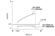
図8の説明に入る前に、この実施例における放水作業が実行されているか否か、換言すれば、ポンプ負荷状態およびポンプ無負荷状態のいずれであるかの判断について概説する。図9は、放水作業時(ポンプ負荷状態)および放水作業停止時(ポンプ無負荷状態)のエンジン回転数NEに対するエンジン出力OPの特性を示すグラフである。尚、エンジン出力OPは、エンジン負荷を表す値(パラメータ)である。 Before entering the description of FIG. 8, an outline of whether or not the water discharge operation in this embodiment is being performed, in other words, whether the pump is in a load state or a no-pump state is described. FIG. 9 is a graph showing the characteristics of the engine output OP with respect to the engine speed NE during the water discharge operation (pump load state) and when the water discharge operation is stopped (pump no load state). The engine output OP is a value (parameter) representing the engine load.
図9に示す如く、エンジン回転数NEに対するエンジン出力OPの特性は、放水作業時(ポンプ負荷状態)と放水作業停止時(ポンプ無負荷状態)で大きく異なる(2極化されている)。この特性に基づいて、エンジン出力OPがしきい値OP1(例えば、1.0[PS]とする)以上か否かを判断することで、放水作業時であるか否か(ポンプが負荷状態あるいはポンプ無負荷状態のいずれであるか)を判断するようにした。 As shown in FIG. 9, the characteristics of the engine output OP with respect to the engine speed NE are greatly different (bipolarized) when the water discharge operation (pump load state) and when the water discharge operation is stopped (pump no load state). Based on this characteristic, it is determined whether or not the engine output OP is greater than or equal to a threshold value OP1 (for example, 1.0 [PS]). Whether the pump is in a no-load state) was determined.
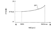
図10は、エンジン出力OPがしきい値OP1における、作業停止時回転数NEDi(アイドリング回転数)からNEDmax(作業時回転数NEDaが取り得る最大値)までのエンジン回転数NEに対するスロットル開度θTHの特性を示すグラフである。 FIG. 10 shows the throttle opening degree θTH with respect to the engine speed NE from the engine stop speed NEDi (idling engine speed) to NEDmax (the maximum value that the engine speed NEDA can take) when the engine output OP is the threshold value OP1. It is a graph which shows the characteristic.
図10に示す如く、エンジン出力OPが一定の値(所定値。例えば、しきい値OP1)であるときのエンジン回転数NEに対するスロットル開度θTHは、予め実験を通じてマップ化することができる。即ち、現在のエンジン回転数NEから、エンジン出力OPがしきい値OP1であるときのスロットル開度を求めることができる。例えば、エンジン回転数NEが作業停止時回転数NEDi(アイドリング回転数)であるときのスロットル開度はθTHref(以下「スロットル開度しきい値θTHref」という)となる。 As shown in FIG. 10, the throttle opening degree θTH with respect to the engine speed NE when the engine output OP is a constant value (predetermined value, for example, threshold value OP1) can be mapped in advance through experiments. That is, the throttle opening when the engine output OP is the threshold value OP1 can be obtained from the current engine speed NE. For example, the throttle opening when the engine speed NE is the work stop speed NEDi (idling speed) is θTHref (hereinafter referred to as “throttle opening threshold θTHref”).
そこで、この実施例では現在のスロットル開度θTHと前記スロットル開度しきい値θTHrefを比較し、スロットル開度θTHがスロットル開度しきい値θTHref以上であれば、現在のエンジン出力OPがしきい値OP1以上であると推定するようにした。一方、スロットル開度しきい値θTHref未満であれば、現在のエンジン出力OPがしきい値OP1未満であると推定するようにした。尚、エンジン回転数NEが作業時回転数NEDaであるときも同様に、スロットル開度しきい値θTHrefを、図示の特性から求めることができる。 Therefore, in this embodiment, the current throttle opening θTH is compared with the throttle opening threshold θTHref, and if the throttle opening θTH is equal to or greater than the throttle opening threshold θTHref, the current engine output OP is the threshold. It was estimated that the value was not less than OP1. On the other hand, if it is less than the throttle opening threshold value θTHref, it is estimated that the current engine output OP is less than the threshold value OP1. Similarly, when the engine speed NE is the working speed NEDA, the throttle opening threshold value θTHref can be obtained from the illustrated characteristics.
図8の説明に戻ると、まずS10において、エンジン回転数NEを検出すると共に、検出したエンジン回転数NEをECU102のRAMに保存する。次いでS12に進み、エンジン回転数NEの検出値が所定サイクル分(例えば10サイクル分)保存されたか否か判断する。S12で否定されるときは以降の処理をスキップする一方、S12で肯定されるときは次いでS14に進み、エンジン回転数平均値NEavgを算出する。エンジン回転数平均値NEavgとは、保存した所定サイクル分(10サイクル分)のエンジン回転数NEの平均値である。
Returning to the description of FIG. 8, first, in S10, the engine speed NE is detected, and the detected engine speed NE is stored in the RAM of the
次いでS16に進み、スロットル開度θTHの現在値を検出し、さらにS18に進んでエンジン18の目標回転数NEDが作業停止時回転数NEDi(アイドリング回転数。例えば、2000[rpm]とする)に設定されているか否か判断する。尚、目標回転数NEDは、ECU102の起動時に作業停止時回転数NEDiに設定される。
Next, the routine proceeds to S16, where the current value of the throttle opening θTH is detected, and the routine further proceeds to S18, where the target rotational speed NED of the
S18で肯定されるときは、次いでS20に進み、エンジン出力OPがしきい値OP1以上か否かを推定する。具体的には、前述したようにエンジン回転数平均値NEavg(概略的には、エンジン回転数NE)およびスロットル開度θTHに基づいてエンジン出力OPがしきい値OP1以上か否かを推定し、よって放水作業が実行されているか否かを判断する。 When the result in S18 is affirmative, the program proceeds to S20, where it is estimated whether the engine output OP is equal to or greater than the threshold value OP1. Specifically, as described above, based on the engine speed average value NEavg (roughly, the engine speed NE) and the throttle opening degree θTH, it is estimated whether or not the engine output OP is greater than or equal to the threshold value OP1. Therefore, it is determined whether or not a water discharge operation is being performed.
S20で否定されるとき(エンジン出力OPがしきい値OP1未満(放水作業が実行されていない)と判断されるとき)は以降の処理をスキップして目標回転数NEDが作業停止時回転数NEDiに維持される一方、S20で肯定されるとき(エンジン出力OPがしきい値OP1以上(放水作業が実行されている)と判断されるとき)はS22に進み、第1の所定時間t1にわたって(継続して)エンジン出力OPがしきい値OP1以上であるか否か判断する。尚、この判断は、S20で肯定されたときに図示しない別のプログラムでカウンタをスタートさせ、そのカウンタ値が第1の所定時間t1(例えば1[sec])に達したか否か確認することによって行われる。 When the result in S20 is negative (when it is determined that the engine output OP is less than the threshold value OP1 (the water discharge operation has not been performed)), the subsequent processing is skipped and the target rotational speed NED becomes the rotational speed NEDi when the work is stopped. On the other hand, when the result in S20 is affirmative (when it is determined that the engine output OP is equal to or greater than the threshold value OP1 (the water discharge operation is being performed)), the process proceeds to S22, and over the first predetermined time t1 ( It is determined whether the engine output OP is equal to or greater than the threshold value OP1. This determination is made by starting the counter with another program (not shown) when affirmed in S20, and confirming whether the counter value has reached a first predetermined time t1 (for example, 1 [sec]). Is done by.
S22で否定されるときは以降の処理をスキップして目標回転数NEDが作業停止時回転数NEDiに維持される一方、S22で肯定されるときはS24に進み、操作者によってボリューム58を介して設定された作業時回転数NEDa(例えば、3600[rpm])を読み込む。
When the result in S22 is negative, the subsequent processing is skipped and the target rotational speed NED is maintained at the work-stop rotational speed NEDi, while when the result in S22 is positive, the process proceeds to S24, and the operator operates the
次いでS26に進み、目標回転数NEDをS24で読み込んだ作業時回転数NEDaに変更する(上昇させる)。これにより、ECU102は、エンジン回転数NEが変更された目標回転数NEDに一致するように電動モータ96を制御し、よってエンジン回転数NEが上昇する。
Next, in S26, the target rotational speed NED is changed (increased) to the working rotational speed NEDa read in S24. Thus, the
S26で目標回転数NEDが作業時回転数NEDaに変更されると、次回のプラグラムループ時はS18で否定されてS28に進み、S20同様にエンジン出力OPがしきい値OP1未満か否か、即ち、放水作業が停止された(実行されていない)か否かを判断する。 When the target rotational speed NED is changed to the working rotational speed NEDa in S26, the next program loop is denied in S18 and proceeds to S28, and whether or not the engine output OP is less than the threshold value OP1 as in S20, that is, Then, it is determined whether or not the water discharge work is stopped (not executed).
S28で否定されるとき(エンジン出力OPが所定値OP1以上(放水作業が実行されている)と判断されるとき)は以降の処理をスキップして目標回転数NEDが作業時回転数NEDaに維持される一方、S28で肯定されるとき(エンジン出力OPが所定値OP1未満(放水作業が実行されていない)と判断されるとき)はS30に進み、第2の所定時間t2にわたって(継続して)エンジン出力OPが所定値OP1未満か否か判断する。尚、この判断もS22同様に、S28で肯定されたときに図示しない別のプログラムでカウンタをスタートさせ、そのカウンタ値が第2の所定時間t2(例えば、1[sec])に達したか確認することによって行われる。 When the result in S28 is negative (when it is determined that the engine output OP is equal to or greater than the predetermined value OP1 (the water discharge operation is being performed)), the subsequent processing is skipped and the target rotational speed NED is maintained at the operational rotational speed NEda. On the other hand, when the result in S28 is affirmative (when it is determined that the engine output OP is less than the predetermined value OP1 (the water discharge operation is not performed)), the process proceeds to S30 and continues (continuously) for the second predetermined time t2. ) It is determined whether the engine output OP is less than a predetermined value OP1. As in S22, when this determination is affirmed in S28, the counter is started by another program (not shown), and it is confirmed whether the counter value has reached a second predetermined time t2 (for example, 1 [sec]). Is done by doing.
S30で否定されるときは以降の処理をスキップして目標回転数NEDが作業時回転数NEDaに維持される一方、S30で肯定されるときはS32に進み、目標回転数NEDを作業停止時回転数NEDiに変更する(下降させる)。これにより、ECU102は、エンジン回転数NEが変更された目標回転数NEDに一致するように電動モータ96を制御し、よってエンジン回転数NEが下降する。
When the result in S30 is negative, the subsequent processing is skipped and the target rotational speed NED is maintained at the working rotational speed NEDa. On the other hand, when the result in S30 is positive, the process proceeds to S32, and the target rotational speed NED is rotated when the work is stopped. Change to a number NEDi (lower). Thus, the
このように、この実施例にあっては、エンジン回転数NE(エンジン回転数NEavg)およびスロットル開度θTHを検出(算出)し、それらの値に基づいてエンジン出力OPがしきい値OP1以上か否かを推定し、その結果に応じてエンジン18の回転数NE(目標回転数NED)を変更する、具体的には作業停止時回転数NEDi(アイドリング回転数)とそれよりも高く設定された作業時回転数NEDaとの間で切り換えるように構成したので、放水作業が実行されているか否かを正確に判断することができると共に、操作者によるエンジン回転数の調整作業を不要とすることができる。即ち、自動的に放水作業の実行と停止に応じたエンジン回転数の制御を行うことができ、作業性を向上(安定)させることができる。さらには、作業停止時にエンジン回転数を下降させることで、燃費を向上させつつ騒音を低減させることができる。
Thus, in this embodiment, the engine speed NE (engine speed NEavg) and the throttle opening θTH are detected (calculated), and based on these values, whether the engine output OP is greater than or equal to the threshold value OP1. The rotational speed NE (target rotational speed NED) of the
また、目標回転数NEDが作業停止時回転数NEDiであって第1の所定時間t1にわたってエンジン出力OPがしきい値OP1以上と推定されたとき、エンジン回転数NE(目標回転数NED)を作業停止時回転数NEDiから、それよりも高い値に設定された作業時回転数NEDaに変更する(上昇させる)一方、目標回転数NEDが作業時回転数NEDaであって第2の所定時間t2にわたってエンジン出力OPがしきい値OP1未満と推定されたとき、エンジン回転数NE(目標回転数NED)を作業時回転数NEDaから作業停止時回転数NEDiに変更する(下降させる)ように構成したので、エンジン18に作用する負荷を精度良く判断することができ、よって放水作業の実行と停止に応じたエンジン回転数NEの切り換えをより的確に行うことができる。さらには、エンジン回転数NEが頻繁に切り替わる(ハンチングが生じる)のを防止することができる。
Further, when the target engine speed NED is the operation stop speed NEDi and the engine output OP is estimated to be equal to or greater than the threshold value OP1 over the first predetermined time t1, the engine speed NE (target engine speed NED) is operated. The rotation speed NEDi at the time of stoppage is changed (increased) to a rotation speed NEDA at the time set to a higher value than that at the stop, while the target rotation speed NED is the rotation speed NEED at the time of operation for the second predetermined time t2. When the engine output OP is estimated to be less than the threshold value OP1, the engine rotational speed NE (target rotational speed NED) is changed from the working rotational speed NEda to the working stopped rotational speed NEDi (decrease). The load acting on the
また、操作者が洗浄ガン44に取り付けられたボリューム58を介して作業時回転数NEDaを設定し、所望のエンジン回転数を得ることができるように構成したので、操作者が放水作業を行いながら作業時回転数を変更(所望の水量(水圧)に変更)することができ、よって作業性を一層向上させることができる。さらには、スロットル開度θTHを電動モータ96(アクチュエータ)によって調整するようにしたことから、エンジン回転数NEをボリューム58を介して入力された作業時回転数NEDaに精度よく一致させることができ、よって機械式ガバナを用いたものに比して作業時回転数(水量(水圧))を微調整することが可能となって作業性をより一層向上させることができる。
Further, since the operator can set the working speed NEDA through the
次いで、図11以降を参照し、この発明の第2実施例に係る高圧洗浄機のエンジン回転数制御装置について説明する。 Next, with reference to FIG. 11 and subsequent figures, a description will be given of an engine speed control device for a high pressure washer according to a second embodiment of the present invention.
図11は、第2実施例に係る放水部(洗浄ガン)442の左側面図である。また、図12は、第2実施例に係る高圧洗浄機のエンジン回転数制御の構成を機能的に示すブロック図である。尚、以下の説明において、第1実施例と共通の構成については、同一の符号を付して説明を省略する。 FIG. 11 is a left side view of a water discharge unit (cleaning gun) 442 according to the second embodiment. FIG. 12 is a block diagram functionally showing the configuration of the engine speed control of the high pressure washer according to the second embodiment. In the following description, the same components as those in the first embodiment are denoted by the same reference numerals and the description thereof is omitted.
第2実施例に係る洗浄ガン442にあっては、図11に示すように、トリガ54の付近にトリガセンサ104が配置される。トリガセンサ104は操作者によってトリガ54が図11の矢印方向に操作されたとき、図12に示すように、ECU102にオン信号を出力する一方、然らざるときはオフ信号を出力するようにした。
In the
次いで、図13および図14を参照して第2実施例に係る高圧洗浄機のエンジン回転数制御装置の動作について説明する。図13は、その動作を示すフローチャートであり、ECU102において所定の周期(例えば、20[msec])ごとに実行される。また、図14は、トリガセンサ104の出力に対する目標回転数NEDの変化を表すタイムチャートである。
Next, the operation of the engine speed control device of the high pressure washer according to the second embodiment will be described with reference to FIGS. 13 and 14. FIG. 13 is a flowchart showing the operation, and is executed in the
以下説明すると、S100において、トリガセンサ104がオン信号を出力しているか否か、即ち、放水作業が実行されているか否か判断する。S100で肯定されるときはS102に進み、操作者によってボリューム58を介して設定された作業時回転数NEDa(例えば、3600[rpm])を読み込む。
In the following, in S100, it is determined whether or not the
次いでS104に進み、図14に示す如く、ただちに目標回転数NEDをS102で読み込んだ作業時回転数NEDaに変更する(上昇させる)。これにより、ECU102は、エンジン回転数NEが変更された目標回転数NEDに一致するように電動モータ96を制御し、よってエンジン回転数NEが上昇する。尚、オン信号が出力されている間は、エンジン回転数NEが作業時回転数NEDaに維持される。
Next, in S104, as shown in FIG. 14, the target rotational speed NED is immediately changed (increased) to the working rotational speed NEDa read in S102. Thus, the
一方、S100で否定されるとき、即ち、トリガセンサ104がオフ信号を出力しているときはS106に進み、図14に示す如く、ただちに目標回転数NEDを作業停止時回転数NEDi(例えば、2000[rpm])に変更する(下降させる)。これにより、ECU102は、エンジン回転数NEが変更された目標回転数NEDに一致するように電動モータ96を制御し、よってエンジン回転数NEが下降する。尚、オフ信号が出力されている間は、回転数NEが作業停止時回転数NEDiに維持される。
On the other hand, when the result in S100 is negative, that is, when the
尚、残余の構成は第1実施例と同様であるので、説明を省略する。 Since the remaining configuration is the same as that of the first embodiment, description thereof is omitted.
このように、第2実施例にあっては、洗浄ガン442が操作されることによってトリガセンサ104からオン信号が出力されると、エンジン18の回転数NE(目標回転数NED)が作業停止時回転数NEDiから作業時回転数NEDaに変更される一方、オフ信号が出力されると、エンジン回転数NE(目標回転数NED)が作業時回転数NEDaから作業停止時回転数NEDiに変更されるように構成したので、簡素な構成で放水作業の実行と停止に応じたエンジン回転数にすることができ、よって作業性を向上(安定)させることができる。さらには、作業停止時にエンジン回転数を下降させるように構成したので、燃費を向上させつつ騒音を低減させることができる。
As described above, in the second embodiment, when the ON signal is output from the
以上の如く、この発明の第1および第2実施例にあっては、搭載されたエンジン(18)でポンプ(20)を駆動して加圧しつつ放水部(洗浄ガン44,442)から放水して洗浄する高圧洗浄機(10)のエンジン回転数制御装置において、前記エンジン(18)の吸気路(80)に設けられたスロットルバルブ(94)の開度(θTH)を調整するアクチュエータ(電動モータ96)と、放水作業が実行されているか否かを判断する作業実行判断手段(ECU102。図8フローチャートのS20,S28、図13フローチャートのS100)と、前記作業実行判断手段により、前記放水作業が実行されていると判断されるとき、エンジン回転数(NE)を作業時回転数(NEDa)に上昇させる(図8フローチャートのS26、図13フローチャートのS104)一方、前記放水作業が実行されていないと判断されるとき、前記エンジン回転数(NE)を作業停止時回転数(NEDi)に下降させる(図8フローチャートのS32、図13フローチャートのS106)ように前記アクチュエータ(96)の駆動を制御するエンジン回転数制御手段(102)とを備えるように構成した。
As described above, in the first and second embodiments of the present invention, the pump (20) is driven by the mounted engine (18) to pressurize and discharge water from the water discharge section (cleaning
この発明の第1実施例にあっては、前記エンジン(18)の回転数(NE)を検出するエンジン回転数検出手段(クランク角センサ100、図8フローチャートのS10,S14)と、前記スロットルバルブ(94)の開度(θTH)を検出するスロットル開度検出手段(スロットル開度センサ98、図8フローチャートのS16)と、前記検出されたエンジン回転数(NE)とスロットル開度(θTH)に基づいて前記エンジン(18)の出力(OP)がしきい値(OP1)以上か否かを推定するエンジン出力推定手段(ECU102。図8フローチャートのS20,S28)とを備えると共に、前記作業実行判断手段は、前記エンジン(18)の出力(OP)が前記しきい値(OP1)以上と推定されたとき、前記放水作業が実行されていると判断する(図8フローチャートのS20,S28)ように構成した。
In the first embodiment of the present invention, engine speed detecting means (crank
また、前記作業実行判断手段(ECU102)は、所定時間(t1)以上継続して前記エンジンの出力(OP)が前記しきい値(OP1)以上と推定されたとき、前記放水作業が実行されていると判断する(図8フローチャートのS20,S22)ように構成した。 The work execution determining means (ECU 102) executes the water discharge work when the engine output (OP) is estimated to be equal to or greater than the threshold value (OP1) continuously for a predetermined time (t1) or longer. (S20 and S22 in the flowchart of FIG. 8).
また、この発明の第2実施例にあっては、さらに、前記放水部(洗浄ガン442)に取り付けられて操作者によって操作可能な放水実行手段(トリガ54)と、前記操作者によって前記放水実行手段が操作されたとき、放水実行信号を出力する放水実行信号出力手段(トリガセンサ104)とを備えると共に、前記作業実行判断手段(ECU102)は、前記放水実行信号出力手段から前記放水実行信号が入力されたとき、前記放水作業が実行されていると判断する(図13フローチャートのS100)ように構成した。 Further, in the second embodiment of the present invention, a water discharge execution means (trigger 54) attached to the water discharge section (cleaning gun 442) and operable by an operator, and the water discharge execution by the operator. And a discharge execution signal output means (trigger sensor 104) that outputs a discharge execution signal when the means is operated, and the work execution determination means (ECU 102) receives the discharge execution signal from the discharge execution signal output means. When input, it is determined that the water discharge operation is being executed (S100 in the flowchart of FIG. 13).
また、この発明の第1および第2実施例にあっては、さらに、前記放水部(洗浄ガン44,442)に取り付けられて操作者によって操作可能なエンジン回転数変更指示入力手段(ボリューム58)を備えると共に、前記エンジン回転数制御手段(ECU102)は、前記エンジン回転数変更指示入力手段からの指示が入力されたとき、前記作業時回転数(NEDa)を変更する(図8フローチャートのS24、図13フローチャートのS102)ように構成した。
In the first and second embodiments of the present invention, an engine speed change instruction input means (volume 58) that is attached to the water discharge section (cleaning
尚、上記において、作業時回転数NEDa、作業停止時回転数NEDi、しきい値OP1、第1および第2所定時間t1,t2の数値を具体的に示したが、その値に限られないのは言うまでもない。 In the above description, the numerical values of the working speed NEDA, the working speed NEDi, the threshold value OP1, and the first and second predetermined times t1 and t2 are specifically shown, but not limited thereto. Needless to say.
また、スロットルバルブ94を開閉するアクチュエータとしてステッピングモータを使用したが、DCモータやロータリーソレノイドなど、他のアクチュエータを使用するようにしても良い。
Further, although the stepping motor is used as the actuator for opening and closing the
また、洗浄に用いられる流体として水を例示したが、それに限られるものではなく、洗浄液、さらには塗料などであっても良いことは言うまでもない。 Moreover, although water was illustrated as a fluid used for washing | cleaning, it is not restricted to it, and it cannot be overemphasized that a washing | cleaning liquid and also a coating material etc. may be sufficient.
10 高圧洗浄機
18 エンジン
20 ポンプ
44,442 洗浄ガン(放水部)
54 トリガ(放水実行手段)
58 ボリューム(エンジン回転数変更指示入力手段)
94 スロットルバルブ
96 電動モータ(アクチュエータ)
98 スロットル開度センサ(スロットル開度検出手段)
100 クランク角センサ(エンジン回転数検出手段)
102 ECU(作業実行判断手段、エンジン回転数制御手段、エンジン出力推定手段)
104 トリガセンサ(放水実行信号出力手段)
10
54 Trigger (Water discharge execution means)
58 volume (engine speed change instruction input means)
94
98 Throttle opening sensor (throttle opening detecting means)
100 Crank angle sensor (engine speed detection means)
102 ECU (work execution determination means, engine speed control means, engine output estimation means)
104 Trigger sensor (water discharge execution signal output means)
Claims (5)
In addition, an engine speed change instruction input means attached to the water discharge section and operable by an operator is provided, and the engine speed control means receives an engine speed change instruction from the engine speed change instruction input means. The engine rotation speed control device for a high-pressure washing machine according to any one of claims 1 to 4, wherein when the operation is performed, the rotation speed during operation is changed.
Priority Applications (1)
| Application Number | Priority Date | Filing Date | Title |
|---|---|---|---|
| JP2004117178A JP2005299519A (en) | 2004-04-12 | 2004-04-12 | Engine speed control device for high pressure washer |
Applications Claiming Priority (1)
| Application Number | Priority Date | Filing Date | Title |
|---|---|---|---|
| JP2004117178A JP2005299519A (en) | 2004-04-12 | 2004-04-12 | Engine speed control device for high pressure washer |
Publications (1)
| Publication Number | Publication Date |
|---|---|
| JP2005299519A true JP2005299519A (en) | 2005-10-27 |
Family
ID=35331369
Family Applications (1)
| Application Number | Title | Priority Date | Filing Date |
|---|---|---|---|
| JP2004117178A Withdrawn JP2005299519A (en) | 2004-04-12 | 2004-04-12 | Engine speed control device for high pressure washer |
Country Status (1)
| Country | Link |
|---|---|
| JP (1) | JP2005299519A (en) |
Cited By (6)
| Publication number | Priority date | Publication date | Assignee | Title |
|---|---|---|---|---|
| EP2246548A1 (en) * | 2009-04-27 | 2010-11-03 | Honda Motor Co., Ltd. | Load condition detection apparatus for general-purpose engine |
| EP2246547A1 (en) * | 2009-04-27 | 2010-11-03 | Honda Motor Co., Ltd. | Control apparatus for general-purpose engine |
| US7926740B2 (en) | 2007-04-04 | 2011-04-19 | Black & Decker Inc. | Pressure washer system and operating method |
| JP2012125685A (en) * | 2010-12-15 | 2012-07-05 | Shinmaywa Industries Ltd | High pressure cleaning apparatus, and high pressure cleaning car including the same |
| CN103321764A (en) * | 2012-03-19 | 2013-09-25 | 本田技研工业株式会社 | Control apparatus of fluid pump |
| US10434630B2 (en) * | 2016-05-18 | 2019-10-08 | Graco Minnesota Inc. | Vapor abrasive blasting system with closed loop flow control |
-
2004
- 2004-04-12 JP JP2004117178A patent/JP2005299519A/en not_active Withdrawn
Cited By (9)
| Publication number | Priority date | Publication date | Assignee | Title |
|---|---|---|---|---|
| US7926740B2 (en) | 2007-04-04 | 2011-04-19 | Black & Decker Inc. | Pressure washer system and operating method |
| EP2246548A1 (en) * | 2009-04-27 | 2010-11-03 | Honda Motor Co., Ltd. | Load condition detection apparatus for general-purpose engine |
| EP2246547A1 (en) * | 2009-04-27 | 2010-11-03 | Honda Motor Co., Ltd. | Control apparatus for general-purpose engine |
| JP2010276017A (en) * | 2009-04-27 | 2010-12-09 | Honda Motor Co Ltd | General-purpose internal combustion engine load state detection device |
| US8347858B2 (en) | 2009-04-27 | 2013-01-08 | Honda Motor Co., Ltd. | Load condition detection apparatus for general-purpose engine |
| US8489310B2 (en) | 2009-04-27 | 2013-07-16 | Honda Motor Co., Ltd | Control apparatus for general-purpose engine |
| JP2012125685A (en) * | 2010-12-15 | 2012-07-05 | Shinmaywa Industries Ltd | High pressure cleaning apparatus, and high pressure cleaning car including the same |
| CN103321764A (en) * | 2012-03-19 | 2013-09-25 | 本田技研工业株式会社 | Control apparatus of fluid pump |
| US10434630B2 (en) * | 2016-05-18 | 2019-10-08 | Graco Minnesota Inc. | Vapor abrasive blasting system with closed loop flow control |
Similar Documents
| Publication | Publication Date | Title |
|---|---|---|
| EP1845249B1 (en) | High-pressure fuel pump control device for engine | |
| JP5267446B2 (en) | Fuel supply device for internal combustion engine | |
| JP4921515B2 (en) | Control device for general-purpose internal combustion engine | |
| US7814888B2 (en) | Method for operating an internal combustion engine | |
| JP2006348908A (en) | Engine control device, engine control system and engine control method | |
| US7085645B2 (en) | Engine speed control system for snow remover | |
| US7536997B2 (en) | Two-point control of a high-pressure pump for direct-injecting gasoline engines | |
| JP2005299519A (en) | Engine speed control device for high pressure washer | |
| JP5692131B2 (en) | High pressure pump control device | |
| JP3772518B2 (en) | Engine operation control device | |
| JP2636394B2 (en) | Fuel injection device | |
| JP2005016436A (en) | Lawn mower engine speed control device | |
| JP4308126B2 (en) | High pressure washer control device | |
| JP4383387B2 (en) | Electronic governor device for general-purpose internal combustion engine | |
| JP5851736B2 (en) | Fuel supply device | |
| JP2009013916A (en) | Start control device for internal combustion engine | |
| US9926870B2 (en) | Warm-up control apparatus for general-purpose engine | |
| JPH0777118A (en) | Fuel supply device for internal combustion engine | |
| JP2006170037A (en) | Control device for concrete cutter | |
| JP4516370B2 (en) | Control device and control method for high-pressure fuel pump of engine | |
| JP2005076522A (en) | General-purpose engine throttle device | |
| JPH11125161A (en) | Fuel supply device for internal combustion engine | |
| JP5341845B2 (en) | General-purpose engine control device | |
| JP3702641B2 (en) | Engine idle operation control device | |
| JPH0886233A (en) | Engine control device and pump device |
Legal Events
| Date | Code | Title | Description |
|---|---|---|---|
| A300 | Withdrawal of application because of no request for examination |
Free format text: JAPANESE INTERMEDIATE CODE: A300 Effective date: 20070703 |