JP2005299328A - Revolving door drive control method and revolving door device - Google Patents
Revolving door drive control method and revolving door device Download PDFInfo
- Publication number
- JP2005299328A JP2005299328A JP2004120554A JP2004120554A JP2005299328A JP 2005299328 A JP2005299328 A JP 2005299328A JP 2004120554 A JP2004120554 A JP 2004120554A JP 2004120554 A JP2004120554 A JP 2004120554A JP 2005299328 A JP2005299328 A JP 2005299328A
- Authority
- JP
- Japan
- Prior art keywords
- door
- panel
- revolving door
- arc
- sensor
- Prior art date
- Legal status (The legal status is an assumption and is not a legal conclusion. Google has not performed a legal analysis and makes no representation as to the accuracy of the status listed.)
- Abandoned
Links
Images
Classifications
-
- E—FIXED CONSTRUCTIONS
- E06—DOORS, WINDOWS, SHUTTERS, OR ROLLER BLINDS IN GENERAL; LADDERS
- E06B—FIXED OR MOVABLE CLOSURES FOR OPENINGS IN BUILDINGS, VEHICLES, FENCES OR LIKE ENCLOSURES IN GENERAL, e.g. DOORS, WINDOWS, BLINDS, GATES
- E06B3/00—Window sashes, door leaves, or like elements for closing wall or like openings; Layout of fixed or moving closures, e.g. windows in wall or like openings; Features of rigidly-mounted outer frames relating to the mounting of wing frames
- E06B3/90—Revolving doors; Cages or housings therefor
- E06B3/903—Revolving doors; Cages or housings therefor consisting of arcuate wings revolving around a parallel axis situated outside the wing, e.g. a cylindrical wing revolving around its axis
-
- E—FIXED CONSTRUCTIONS
- E05—LOCKS; KEYS; WINDOW OR DOOR FITTINGS; SAFES
- E05F—DEVICES FOR MOVING WINGS INTO OPEN OR CLOSED POSITION; CHECKS FOR WINGS; WING FITTINGS NOT OTHERWISE PROVIDED FOR, CONCERNED WITH THE FUNCTIONING OF THE WING
- E05F15/00—Power-operated mechanisms for wings
- E05F15/60—Power-operated mechanisms for wings using electrical actuators
- E05F15/603—Power-operated mechanisms for wings using electrical actuators using rotary electromotors
- E05F15/608—Power-operated mechanisms for wings using electrical actuators using rotary electromotors for revolving wings
-
- E—FIXED CONSTRUCTIONS
- E05—LOCKS; KEYS; WINDOW OR DOOR FITTINGS; SAFES
- E05F—DEVICES FOR MOVING WINGS INTO OPEN OR CLOSED POSITION; CHECKS FOR WINGS; WING FITTINGS NOT OTHERWISE PROVIDED FOR, CONCERNED WITH THE FUNCTIONING OF THE WING
- E05F15/00—Power-operated mechanisms for wings
- E05F15/70—Power-operated mechanisms for wings with automatic actuation
-
- E—FIXED CONSTRUCTIONS
- E05—LOCKS; KEYS; WINDOW OR DOOR FITTINGS; SAFES
- E05Y—INDEXING SCHEME ASSOCIATED WITH SUBCLASSES E05D AND E05F, RELATING TO CONSTRUCTION ELEMENTS, ELECTRIC CONTROL, POWER SUPPLY, POWER SIGNAL OR TRANSMISSION, USER INTERFACES, MOUNTING OR COUPLING, DETAILS, ACCESSORIES, AUXILIARY OPERATIONS NOT OTHERWISE PROVIDED FOR, APPLICATION THEREOF
- E05Y2900/00—Application of doors, windows, wings or fittings thereof
- E05Y2900/10—Application of doors, windows, wings or fittings thereof for buildings or parts thereof
- E05Y2900/13—Type of wing
- E05Y2900/132—Doors
Landscapes
- Engineering & Computer Science (AREA)
- Civil Engineering (AREA)
- Structural Engineering (AREA)
- Extensible Doors And Revolving Doors (AREA)
- Power-Operated Mechanisms For Wings (AREA)
Abstract
【課題】 回転ドアと出入り口との間に通行者が挟まれることを低減する。
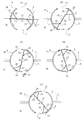
【解決手段】 2つの対向する出入り口10、12を形成する円弧状の外壁パネル6、8に沿って回転自在に、仕切りパネル14が設けられている。仕切りパネル14は、出入り口10、12を開閉する円弧パネル18、20を有している。円弧パネル18、20が出入り口10、12の戸挟み区間を移動する間、低速で仕切りパネル14が回転され、円弧パネル18、20が出入り口10、12を閉鎖する閉じ位置から高速で仕切りパネル14を回転される。
【選択図】 図1PROBLEM TO BE SOLVED: To reduce the number of passersby between a revolving door and an entrance / exit.
A partition panel 14 is provided so as to be rotatable along arcuate outer wall panels 6 and 8 that form two opposing doorways 10 and 12. The partition panel 14 has arcuate panels 18 and 20 that open and close the entrances 10 and 12. The partition panel 14 is rotated at a low speed while the circular arc panels 18 and 20 move in the doorway section of the entrances 10 and 12, and the partition panel 14 is moved at a high speed from the closed position where the arc panels 18 and 20 close the entrances 10 and 12. It is rotated.
[Selection] Figure 1
Description
本発明は、回転ドアの駆動制御方法及び回転ドア装置に関し、特に回転ドアの速度制御に関する。 The present invention relates to a revolving door drive control method and a revolving door device, and more particularly to revolving door speed control.
回転ドア装置としては、例えば特許文献1に開示されているようなものがある。この特許文献1の回転ドア装置では、対向した2つの出入り口を有する円筒状の外壁パネル内に沿って回転ドアが回転する。この回転ドアは、外壁パネルの直径方向に沿って配置された仕切り壁を有している。この仕切り壁の両端に外壁部がそれぞれ設けられている。これら外壁部では、2つの出入り口を同時に閉鎖することが可能な2つの円弧パネルが外壁パネルと同心状に形成され、外壁パネルに沿って回転可能に配置されている。円弧パネルの回転方向の前端縁に直線状の壁部が設けられ、円弧パネルの回転方向の後端縁に凹面壁が設けられ、これら壁部と凹面壁とによって仕切り壁に円弧パネルが結合されている。出入り口を円弧パネルが閉じていない状態で回転ドアが停止しており、出入り口の近傍に設けたセンサが通行者を検知すると、回転ドアが回転を開始する。また、外壁部の直線状へ基部に設けたセンサが、壁部に近づきすぎた通行者を検知すると、回転ドアは停止させられる。 As a revolving door apparatus, there exist some which are indicated by patent documents 1, for example. In the revolving door device of Patent Document 1, the revolving door rotates along the inside of a cylindrical outer wall panel having two facing doorways. This revolving door has a partition wall arranged along the diameter direction of the outer wall panel. Outer wall portions are provided at both ends of the partition wall. In these outer wall portions, two arc panels capable of simultaneously closing two doorways are formed concentrically with the outer wall panel, and are arranged rotatably along the outer wall panel. A straight wall is provided at the front edge of the arc panel in the rotation direction, a concave wall is provided at the rear edge of the arc panel in the rotation direction, and the arc panel is coupled to the partition wall by the wall and the concave wall. ing. The revolving door is stopped in a state in which the arc panel is not closed at the doorway, and when the sensor provided in the vicinity of the doorway detects a passerby, the revolving door starts rotating. Moreover, when the sensor provided in the base part to the linear shape of the outer wall part detects a passerby who has approached the wall part too much, the revolving door is stopped.
上記の回転ドア装置では、出入り口から外壁パネル内に通行者が入った後、通行者が直線状の壁部に近づきすぎたときに、回転ドアが停止するように構成されている。しかし、回転ドアが出入り口の一部を閉じ始めてから完全に閉じるまでの間(戸挟み区間)に、円弧パネルと出入り口の縁との間に通行者が挟まれることを防止するための対策については開示していない。例えば各種のセンサを配置し、戸挟み区間に通行者が存在する場合に、回転ドアを停止させることが考えられる。しかし、この回転ドア装置では、回転ドアは常に一定の速度で回転しているので、各種センサが通行者を検知しても、回転ドアを即座に停止させることは困難で、回転ドアと出入り口の縁との間に通行者が挟まれる可能性が高い。 The above revolving door device is configured such that the revolving door stops when the passerby gets too close to the linear wall after the passerby enters the outer wall panel from the doorway. However, for measures to prevent a passerby from being caught between the arc panel and the edge of the doorway, from the time when the revolving door starts to close part of the doorway to the time when it completely closes (door pinching section) Not disclosed. For example, it is conceivable to dispose the various sensors and stop the revolving door when a passerby exists in the door-spanning section. However, with this revolving door device, the revolving door always rotates at a constant speed, so even if various sensors detect a passerby, it is difficult to stop the revolving door immediately. There is a high possibility that passersby will be caught between the edges.
本発明は、回転ドアと出入り口の縁との間に通行者が挟まれることを低減することができる回転ドアの駆動制御方法及び回転ドア装置を提供することを目的とする。 An object of this invention is to provide the drive control method and rotary door apparatus of a rotary door which can reduce that a passerby is pinched | interposed between a rotary door and the edge of an entrance / exit.
本発明による回転ドアの駆動制御方法は、2つの対向する出入り口を開閉する円弧パネルを備えた回転ドアの駆動制御方法であって、前記円弧パネルが前記出入り口の戸挟み区間を移動する間、前記回転ドアを低速で回転駆動させる。戸挟み区間以外の区間では、通常の速度で回転ドアは回転している。また、通常の速度から低速への変更は、ステップ状に行うのではなく、漸減させることが望ましい。円弧パネルは、2つの出入り口を同時に閉鎖することができるものが望ましい。また戸挟み区間は、円弧パネルが出入り口の一部を閉鎖した状態から、出入り口を完全に閉鎖した状態までを言う。出入り口の一部の閉鎖としては、例えば出入り口の半分を超えて閉鎖した状態とすることもできる。 The drive control method for a revolving door according to the present invention is a drive control method for a revolving door provided with an arc panel that opens and closes two opposing doorways, while the arc panel moves in a door-holding section of the doorway. Drive the revolving door at low speed. In the sections other than the door-clamping section, the revolving door is rotating at a normal speed. In addition, it is desirable to gradually reduce the change from the normal speed to the low speed, not in a stepped manner. It is desirable that the arc panel can close two entrances at the same time. Moreover, a door pinching section says from the state which the circular arc panel closed a part of entrance / exit to the state which closed the entrance / exit completely. As a part of the entrance / exit closure, for example, a state in which the entrance / exit is over half of the entrance / exit can be closed.
この駆動制御方法では、戸挟み区間では、回転ドアは低速で駆動されている。従って、戸挟み区間で通行者が検知され、直ちに制動を掛けた場合、その制動距離が短くなり、円弧パネルと出入り口の縁との間に通行者が挟まれる可能性が非常に小さくなる。 In this drive control method, the revolving door is driven at a low speed in the door holding section. Therefore, when a passerby is detected in the door-clamping section and braking is immediately applied, the braking distance is shortened, and the possibility that the passerby is caught between the arc panel and the edge of the doorway becomes very small.
本発明による回転ドア装置は、円弧状の外壁パネルを有している。この外壁パネルは、2つの対向する出入り口を形成している。この外壁パネルに沿って回転自在に仕切りパネルが設けられ、この仕切りパネルは、前記2つの出入り口を開閉する円弧パネルを有している。円弧パネルによる2つの出入り口の閉鎖は、同時に行うことが望ましい。仕切りパネルは駆動部によって回転させられる。駆動部は、異なる速度で回転ドアを回転させることができ、制動手段を備えることが望ましい。この駆動部を駆動制御手段が制御する。駆動制御手段は、前記円弧パネルが前記出入り口の戸挟み区間を移動する間、前記駆動部を低速で回転駆動させる低速制御手段と、前記円弧パネルが前記出入り口を閉鎖する閉じ位置から前記駆動部を高速で回転駆動させる高速制御手段とを、有している。戸挟み区間は、円弧パネルが出入り口の一部を閉じた位置から前記閉じ位置までの区間とすることができる。高速制御手段は、前記閉じ位置から前記戸挟み区間の開始位置までの間を高速で回転させることが望ましい。また、駆動制御手段は、戸挟み区間に通行者等が存在するか否かを検知する検知手段から信号の入力を受け、検知手段の信号が戸挟み区間に通行者が存在することを表すとき、回転ドアの回転を停止させることが望ましい。 The revolving door device according to the present invention has an arc-shaped outer wall panel. The outer wall panel forms two opposing doorways. A partition panel is provided to be rotatable along the outer wall panel, and the partition panel has an arc panel that opens and closes the two doorways. It is desirable that the two entrances are closed simultaneously by the arc panel. The partition panel is rotated by the drive unit. The drive unit can rotate the revolving door at different speeds, and preferably includes braking means. The drive control unit controls this drive unit. The drive control means includes a low speed control means for rotating the drive unit at a low speed while the arc panel moves in the doorway section of the doorway, and a drive position from the closed position where the arc panel closes the doorway. High-speed control means for rotationally driving at high speed. The door sandwiching section can be a section from a position where the arc panel closes a part of the entrance to the closing position. It is desirable that the high-speed control means rotate at a high speed between the closed position and the start position of the door pinching section. In addition, when the drive control means receives a signal input from the detection means for detecting whether or not a passerby exists in the door pinching section, and the signal of the detection means indicates that the passerby exists in the door pinching section It is desirable to stop the rotation of the revolving door.
このように構成された回転ドア装置では、戸挟み区間を円弧パネルが移動している間には、円弧パネルは低速で移動している。従って、戸挟み区間で通行者が検知されて、円弧パネルの回転が停止されると、短い制動距離で円弧パネルが停止し、円弧パネルと出入り口の縁との間に、通行者が挟まれる可能性を非常に小さくできる。 In the thus configured rotating door device, the arc panel is moving at a low speed while the arc panel is moving in the door pinching section. Therefore, if a passerby is detected in the door pinching section and rotation of the arc panel is stopped, the arc panel stops at a short braking distance, and a passerby can be caught between the arc panel and the edge of the doorway. The sex can be very small.
以上のように、本発明によれば、戸挟み区間で通行者が検知されて、円弧パネルの回転が停止されると、短い制動距離で円弧パネルが停止し、円弧パネルと出入り口の縁との間に、通行者が挟まれる可能性を低減させることができる。 As described above, according to the present invention, when a passerby is detected in the door pinching section and rotation of the arc panel is stopped, the arc panel stops at a short braking distance, and the arc panel and the edge of the entrance / exit The possibility that a passerby is caught between them can be reduced.
本発明の一実施形態の回転ドア装置は、図1(a)乃至(e)に示すように、外壁パネル2を有している。この外壁パネル2は、例えばビルの内外を区画している壁部4に、内外に貫通するように形成した開口に取り付けられ、平面的に見て同一の円周上に位置するように配置された2つの円弧状外壁6、8を有している。この円弧状外壁6、8の間に、外壁パネル2に出入りするための開口10、12が対向するように配置されている。これら開口10、12は、壁部4に直交する方向に位置している。
The revolving door apparatus of one Embodiment of this invention has the
外壁パネル2内に、仕切りパネル14が配置されている。仕切りパネル14は、平面的に見て外壁パネル4の直径方向に沿って配置されている。この仕切りパネル14の中央部に、自動ドア、例えば両引きのスライドドア16が配置されている。
A
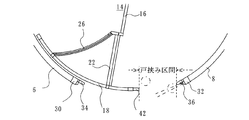
図3に拡大して示すように、仕切りパネル14の先端部には、円弧パネル18、20が取り付けられている。これら円弧パネル18、20は、円弧状外壁6、8と同心状に形成されている。図1(d)に示すように、円弧パネル18、20は、出入り口10、12を閉鎖することができる大きさに形成され、仕切りパネル14の中心を対称点とする点対称に配置されている。従って、円弧パネル18、20は同時に出入り口10、12を閉鎖することができる。この円弧パネル18、20とスライドドア16との間には、平面的に見て直線状の壁体22、24と平面的に見て湾曲状の壁体26、28とが設けられている。これらによって展示空間がそれぞれ形成されている。
As shown in an enlarged view in FIG. 3,
この仕切りパネル14、円弧パネル18、20等は、図示していないが円弧状外壁6、8の上部を繋ぐ回転天井に吊り下げられ、この回転天井が回転することによって、図1(a)乃至(e)に示すように、仕切りパネル14、円弧パネル18、20等は例えば反時計方向に回転させられる。これによって、円弧パネル18、20は、円弧状外壁6、8の内面に沿って回転する。
Although not shown, the
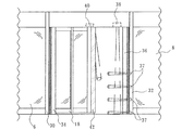
図2に示すように、出入り口12の両縁に垂直に立っている方立30、32には緩衝ゴム34、36が設けられている。方立32側の緩衝ゴム36はゴムスイッチ36として形成されており、このゴムスイッチ36に通行者が接触したとき、ゴムスイッチ36が通行者を検知する。また、仕切りパネル14の回転方向の前方側にある方立32には、その長さ方向に床面側から所定の間隔を隔てて複数、例えば4個のコラムセンサ37が設けられている。図2に示すようなコラムセンサ37の4つの検知領域のいずれかに通行者が入ったとき、通行者を検知する。これら検知領域は、後述する戸挟み区間よりも幾分外方に設定されている。また、上述した回転天井の周囲にある固定天井の方立32の近傍には、戸挟み防止センサ38が設けられている。戸挟み防止センサ38は、各コラムセンサ37の検知領域と交差して床面に向かう検知領域を有している。この検知領域に通行者が入ったとき、この通行者を戸挟み防止センサ38が検知する。この戸挟み防止センサの検知領域も、後述する戸挟み区間内にある。これらセンサ36、37、38が、通行者を検知したとき、仕切りパネル14は停止させられる。
As shown in FIG. 2,
また、固定天井には、戸挟み区間検知手段、例えばリードスイッチ40が設けられている。このリードスイッチ40は、円弧パネル18の前端が、図3に示す戸挟み区間42に到達したときに、第1の状態、例えばオン状態になり、戸挟み区間42を離れたときに、第2の状態、例えばオフ状態になる。戸挟み区間42は、円弧パネル18が、出入り口12の一部、例えばその半分よりも幾分多くを閉じた状態から円弧パネル18が出入り口12を完全に閉じる閉じ位置まで円弧パネル18が通過する軌跡上の区間である。リードスイッチ40をオン、オフさせるために、リードスイッチ40の近傍を通る回転天井には、所定の間隔をおいて永久磁石のN極とS極とが配置されている(図4参照)。円弧パネル18の前端縁が戸挟み区間42を通過していることをリードスイッチ40が検知しているとき、後述するように仕切りパネル14は減速される。
Further, the fixed ceiling is provided with a door pinching section detecting means, for example, a
円弧パネル18の前端縁には、エッジセンサ42が取り付けられ、これに通行者が接触したとき、エッジセンサ42が通行者を検知する。また、回転天井には、円弧パネル18の前方で通行者を検知する床面側に向かう検知領域を形成する戸先センサ44(図4参照)が取り付けられている。この戸先センサの検知領域は、円弧パネル18の前端縁が戸挟み区間に入ったとき、この戸挟み区間よりも幾分外壁パネル2内側を円弧パネル18の走行に沿って移動する。エッジセンサ42、戸先センサ44が通行者を検知したときにも、仕切りパネル14が停止させられる。
An
なお、出入り口10側にも方立ゴムスイッチ36、コラムセンサ37、戸挟み防止センサ38が設けられ、円弧パネル20の前端縁側にもエッジセンサ42、戸先センサ44が設けられている。なお、スライドドア16の通行者との接触を防止するためのセンサ等も設けられているが、本願発明とは直接に関連しないので、説明は省略する。
A
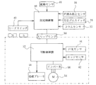
図4に示すように、方立ゴムスイッチ36、コラムセンサ37、戸挟み防止センサ38、リードスイッチ40は、固定天井側に設けられた固定制御盤46に接続されている。また、この固定制御盤46には、起動センサ48も接続されている。この起動センサ48が通行者を検知したとき、仕切りパネル14が回転させられる。固定制御盤46は、スリップリング50を介して回転天井側に設けられた可動制御盤52に接続され、各センサからの情報が可動制御盤52に伝達される。可動制御盤52にはエッジセンサ42、戸先センサ44が接続されている。これらエッジセンサ42、戸先センサ44からの情報、スリップリング50を介しての方立ゴムスイッチ36、コラムセンサ37、戸挟み防止センサ38、リードスイッチ40からの情報に基づいて、可動制御盤52は、回転天井の駆動部、例えばモータ54の回転開始、停止、速度制御を行う。この制御には、駆動制御部、例えばインバータ56を使用している。また、可動制御盤52には、制動手段、例えば電磁ブレーキ58が接続されている。この電磁ブレーキ58は、回転天井を制動するために使用される。
As shown in FIG. 4, the
なお、回転天井側には、この他にスライドドア16の駆動部及び制御部、スライドドアを開閉するためのセンサが存在するが、本願発明とは直接に関連しないので、説明は省略する。
In addition to this, there are a drive unit and a control unit for the
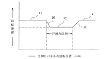
例えば図1(a)に示すように仕切りパネル14が、壁部4と平行な状態、即ち中立位置で停止しているとする。起動センサ48が通行者を検知すると、同図(b)に示すように仕切りパネル14が反時計方向に回転を開始する。このときの速度は、図5に示すように予め定めた一定の速度V1である。そして、同図(c)に示すように仕切りパネル14の前端縁が戸挟み区間に到達し、リードスイッチ40がオンになると、図5に示すように減速域DEを経て速度V2(V2<V1)に減速される。即ち、速度V1が高速で、速度V2が低速である。減速域DEの時間は短いことが望ましいので、電磁ブレーキ58とインバータ56による減速とが併用されて減速される。
For example, as shown in FIG. 1A, it is assumed that the
速度V2の状態は、同図(d)に示すように円弧パネル18が出入り口12を完全に閉じ、かつ円弧パネル20が出入り口10を完全に閉じる閉じ位置まで継続される。この戸挟み区間を円弧パネル18の前端縁が通過し終わったとき、リードスイッチ40がオフとなり、図5に示すように加速域ACを経て再び速度V1で仕切りパネル14が回転する。
The state of the speed V2 is continued until the
このように戸挟み区間では、仕切りパネル14の速度が、低速度V2に低下させてある。従って、図1(c)に示すように、通行者が戸挟み区間内に入ろうとすると、コラムセンサ36、コラムセンサ37、戸挟み防止センサ38、エッジセンサ42、戸先センサ44のいずれかによって通行者が検知され、可動制御盤52によって電磁ブレーキ58が作動する。これによって、短い制動距離で仕切りパネル14が停止し、通行者が円弧パネル18の前端縁と出入り口12の方立32との間に挟まれることを未然に防止できる。出入り口10側においても同様である。
Thus, the speed of the
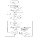
このように制御を行うため、可動制御盤52は、例えば図6のフローチャートで示すように動作する。
In order to perform control in this way, the
この回転ドア装置に電源がオンされると、まず図1(a)に示す中立位置に仕切りパネル14を移動させる(ステップS2)。そして、起動センサ48がオンであるか判断する(ステップS4)。この判断の答えがノーの場合、ステップS2から再び実行する。
When the power is turned on, the
ステップS4の判断の答えがイエスの場合、可動制御盤52は、仕切りパネル14を高速回転させる(ステップS6)。即ち、高速度V1で回転させる。次に、リードスイッチ40がオンであるか判断する(ステップS8)。この判断の答えがノーの場合、仕切りパネル18の前端縁は戸挟み区間にまだ到達していないので、ステップS6から再び繰り返し、高速回転を継続する。
If the answer to the determination in step S4 is yes, the
ステップS8の判断の答えがイエスになると、円弧パネル18の前端縁が戸挟み区間内を通過中であるので、仕切りパネル14を低速回転させる(ステップS10)。即ち、仕切りパネル14の速度を低速度V2とする。
If the answer to the determination in step S8 is yes, since the front edge of the
次に、安全センサがオンであるか、即ち、方立ゴムスイッチ36、コラムセンサ37、戸挟み防止センサ38、エッジセンサ42、戸先センサ44のいずれかが通行者を検知していないか判断する(ステップS12)。この判断の答えがノーであると、次に、リードスイッチ40がオフであるか、即ち戸挟み区間を円弧パネル18の前端縁が完全に通過したか判断する(ステップS14)。この判断の答えがノーであると、ステップS10から再び実行する。また、このステップS14の判断の答えがイエスであると、ステップS6から再び実行する。従って、戸挟み区間を円弧パネル18の前端縁が通過中に、通行者を安全センサが検知しないと、戸挟み区間中、継続して低速度V2で仕切りパネル14が走行し、戸挟み区間を通過し終わると、再び高速度V1で仕切りパネル14が走行する。
Next, it is determined whether the safety sensor is on, that is, any of the
ステップS12の判断の答えがイエスであると、即ち、戸挟み区間を円弧パネル18の前端縁が通過中に、安全センサがオンとなると、可動制御盤52は、インバータ56を介してモータ54を停止させ、かつ電磁ブレーキ58を作動させて、仕切りパネル14を停止させる(ステップS16)。低速度V2で走行中に、モータ54が停止され、かつ電磁ブレーキ58が作動するので、短い制動距離で仕切りパネル14が停止する。
If the answer to the determination in step S <b> 12 is yes, that is, if the safety sensor is turned on while the front edge of the
ステップS16に続いて、安全センサがオンであるか再び判断される(ステップS18)。この判断の答えがイエスであると、戸挟み区間に通行者がまだ存在するので、ステップS16から再び実行し、仕切りパネル14の停止状態を維持する。ステップS18の判断の答えがノーであると、戸挟み区間には通行者が存在しないので、ステップS10を再び実行し、低速で仕切りパネル14を回転させる。
Following step S16, it is determined again whether the safety sensor is on (step S18). If the answer to this determination is yes, there are still passersby in the door-span section, so the process is executed again from step S16, and the stop state of the
上記の実施の形態では、戸挟み区間を、出入り口10、12の半分以上を円弧パネル18、20が閉じた位置から閉じ位置までとしたが、これに限ったものではなく、例えば戸挟み区間の始点は、出入り口10、12を円弧パネル18、20が閉じ始めた位置から閉じ位置までの範囲内の任意の位置に決定することができる。また、上記の実施の形態では、コラムセンサ37、戸挟み防止センサ38は戸挟み区間よりも幾分外側または内側で通行者を検知するように構成したが、これに限らず、例えば戸挟み区間内で通行者を検知するように構成することもできる。
In the above-described embodiment, the door-holding section is set to more than half of the
2 外壁パネル
6 8 円弧状壁部
10 12 出入り口
14 仕切りパネル
18 20 円弧パネル
2
Claims (2)
前記円弧パネルが前記出入り口の戸挟み区間を移動する間、前記回転ドアを低速で回転駆動させることを特徴とする、回転ドアの駆動制御方法。 A drive control method for a revolving door with an arc panel that opens and closes two opposing doorways,
A rotary door drive control method, wherein the rotary door is driven to rotate at a low speed while the arc panel moves in a door-holding section of the doorway.
この外壁パネルに沿って回転自在に設けられ、前記2つの出入り口を開閉する円弧パネルを有する仕切りパネルと、
前記仕切りパネルを回転させる駆動部と、
この駆動部を制御する駆動制御手段とを、
備えた回転ドア装置において、
前記駆動制御手段が、前記円弧パネルが前記出入り口の戸挟み区間を移動する間、前記駆動部を低速で回転駆動させる低速制御手段と、前記円弧パネルが前記出入り口を閉鎖する閉じ位置から前記駆動部を高速で回転駆動させる高速制御手段とを、有する回転ドア装置。 An arc-shaped outer wall panel forming two opposing doorways;
A partition panel that is rotatably provided along the outer wall panel and has an arc panel that opens and closes the two doorways;
A drive unit for rotating the partition panel;
Drive control means for controlling the drive unit;
In the provided revolving door device,
The drive control means includes low-speed control means for rotating the drive unit at a low speed while the arc panel moves in the doorway section of the doorway, and the drive unit from a closed position where the arc panel closes the doorway. A revolving door device having high-speed control means for rotating the motor at high speed.
Priority Applications (2)
| Application Number | Priority Date | Filing Date | Title |
|---|---|---|---|
| JP2004120554A JP2005299328A (en) | 2004-04-15 | 2004-04-15 | Revolving door drive control method and revolving door device |
| PCT/JP2005/007225 WO2005100724A1 (en) | 2004-04-15 | 2005-04-14 | Driving control method for revolving door and revolving door device |
Applications Claiming Priority (1)
| Application Number | Priority Date | Filing Date | Title |
|---|---|---|---|
| JP2004120554A JP2005299328A (en) | 2004-04-15 | 2004-04-15 | Revolving door drive control method and revolving door device |
Publications (1)
| Publication Number | Publication Date |
|---|---|
| JP2005299328A true JP2005299328A (en) | 2005-10-27 |
Family
ID=35150049
Family Applications (1)
| Application Number | Title | Priority Date | Filing Date |
|---|---|---|---|
| JP2004120554A Abandoned JP2005299328A (en) | 2004-04-15 | 2004-04-15 | Revolving door drive control method and revolving door device |
Country Status (2)
| Country | Link |
|---|---|
| JP (1) | JP2005299328A (en) |
| WO (1) | WO2005100724A1 (en) |
Cited By (5)
| Publication number | Priority date | Publication date | Assignee | Title |
|---|---|---|---|---|
| JP2008240277A (en) * | 2007-03-26 | 2008-10-09 | Sanwa Shutter Corp | Automatic revolving door |
| JP2013213397A (en) * | 2012-04-01 | 2013-10-17 | Chikura Kogyo Kk | Safety device for automatic revolving door device, and method for controlling the same |
| JP2013256858A (en) * | 2012-06-11 | 2013-12-26 | Chikura Kogyo Kk | Automatic revolving door and control method for the same |
| JP2017048575A (en) * | 2015-08-31 | 2017-03-09 | 三和シヤッター工業株式会社 | Opening and closing control system for automatic door |
| CN110897482A (en) * | 2019-11-28 | 2020-03-24 | 徐州大亚智能科技有限公司 | Intelligent window curtain storage device |
Family Cites Families (2)
| Publication number | Priority date | Publication date | Assignee | Title |
|---|---|---|---|---|
| JPS58101982A (en) * | 1981-12-14 | 1983-06-17 | 株式会社ナブコ | Opening and closing control of automatic door |
| JP2001032626A (en) * | 1999-07-21 | 2001-02-06 | Ykk Corp | Revolving door control device |
-
2004
- 2004-04-15 JP JP2004120554A patent/JP2005299328A/en not_active Abandoned
-
2005
- 2005-04-14 WO PCT/JP2005/007225 patent/WO2005100724A1/en not_active Ceased
Cited By (11)
| Publication number | Priority date | Publication date | Assignee | Title |
|---|---|---|---|---|
| JP2008240277A (en) * | 2007-03-26 | 2008-10-09 | Sanwa Shutter Corp | Automatic revolving door |
| JP2013213397A (en) * | 2012-04-01 | 2013-10-17 | Chikura Kogyo Kk | Safety device for automatic revolving door device, and method for controlling the same |
| CN103362413A (en) * | 2012-04-01 | 2013-10-23 | 千藏工业株式会社 | Automatic revolving door and operation method when automatic revolving door detects danger |
| JP2013256858A (en) * | 2012-06-11 | 2013-12-26 | Chikura Kogyo Kk | Automatic revolving door and control method for the same |
| CN103485644A (en) * | 2012-06-11 | 2014-01-01 | 千藏工业株式会社 | Rotary automatic door and operation method thereof |
| CN103485644B (en) * | 2012-06-11 | 2016-12-14 | 千藏工业株式会社 | Rotary automatic door and operation method thereof |
| CN107035280A (en) * | 2012-06-11 | 2017-08-11 | 千藏工业株式会社 | Rotary automatic door and its operation method |
| JP2017218891A (en) * | 2012-06-11 | 2017-12-14 | 千蔵工業株式会社 | Automatic revolving door and its control method |
| CN107035280B (en) * | 2012-06-11 | 2020-02-28 | 千藏工业株式会社 | Rotary automatic door and operation method thereof |
| JP2017048575A (en) * | 2015-08-31 | 2017-03-09 | 三和シヤッター工業株式会社 | Opening and closing control system for automatic door |
| CN110897482A (en) * | 2019-11-28 | 2020-03-24 | 徐州大亚智能科技有限公司 | Intelligent window curtain storage device |
Also Published As
| Publication number | Publication date |
|---|---|
| WO2005100724A1 (en) | 2005-10-27 |
Similar Documents
| Publication | Publication Date | Title |
|---|---|---|
| JP6388698B2 (en) | Automatic revolving door and control method thereof | |
| US4530183A (en) | Revolving door system | |
| JP2004044109A (en) | Door sensor and door with the door sensor | |
| JPH03264486A (en) | Cage door apparatus of elevator | |
| JP2005299328A (en) | Revolving door drive control method and revolving door device | |
| JP3312245B2 (en) | Control method for keeping the door open automatically | |
| JP3758268B2 (en) | Automatic door opener | |
| JP2003227269A (en) | Automatic door | |
| JP2008063018A (en) | Door device of elevator | |
| JP2006002465A (en) | Revolving door device | |
| JP2001032626A (en) | Revolving door control device | |
| JP2005105810A (en) | Entrance/exit control gate device | |
| JP4449000B2 (en) | Revolving door | |
| JP5000968B2 (en) | Automatic door device | |
| JP2007224620A (en) | Revolving door device | |
| JP4986669B2 (en) | Automatic revolving door | |
| JP3755123B2 (en) | Automatic revolving door | |
| JP2006022605A (en) | Revolving door safety sensor system | |
| JP2005336876A (en) | Revolving door safety device | |
| JP4804891B2 (en) | Door equipment | |
| JP3442967B2 (en) | Automatic revolving door | |
| JP2001032622A (en) | Revolving door control device | |
| JP2000170445A (en) | Rotary door device | |
| JPH06330683A (en) | Control method of sheet shutter having shutters arranged side by side and device thereof | |
| JP3628680B2 (en) | Revolving door device |
Legal Events
| Date | Code | Title | Description |
|---|---|---|---|
| A621 | Written request for application examination |
Free format text: JAPANESE INTERMEDIATE CODE: A621 Effective date: 20070305 |
|
| A762 | Written abandonment of application |
Free format text: JAPANESE INTERMEDIATE CODE: A762 Effective date: 20081010 |