JP2005299080A - Earthquake-resistant bridge pier - Google Patents
Earthquake-resistant bridge pier Download PDFInfo
- Publication number
- JP2005299080A JP2005299080A JP2004111863A JP2004111863A JP2005299080A JP 2005299080 A JP2005299080 A JP 2005299080A JP 2004111863 A JP2004111863 A JP 2004111863A JP 2004111863 A JP2004111863 A JP 2004111863A JP 2005299080 A JP2005299080 A JP 2005299080A
- Authority
- JP
- Japan
- Prior art keywords
- earthquake
- column
- pier
- yield point
- steel
- Prior art date
- Legal status (The legal status is an assumption and is not a legal conclusion. Google has not performed a legal analysis and makes no representation as to the accuracy of the status listed.)
- Withdrawn
Links
- 239000000463 material Substances 0.000 claims abstract description 116
- 229910000831 Steel Inorganic materials 0.000 claims abstract description 97
- 239000010959 steel Substances 0.000 claims abstract description 97
- 238000004519 manufacturing process Methods 0.000 abstract description 3
- 238000003466 welding Methods 0.000 abstract description 3
- 230000035939 shock Effects 0.000 abstract 1
- 238000010008 shearing Methods 0.000 description 10
- 238000010276 construction Methods 0.000 description 8
- 238000013016 damping Methods 0.000 description 7
- 238000006073 displacement reaction Methods 0.000 description 6
- 239000002131 composite material Substances 0.000 description 1
- 238000002955 isolation Methods 0.000 description 1
- 230000002093 peripheral effect Effects 0.000 description 1
Images
Landscapes
- Bridges Or Land Bridges (AREA)
Abstract
Description
本発明は、地震の揺れに耐える耐震橋脚に関する。 The present invention relates to an earthquake-resistant pier that can withstand earthquake shaking.
一般に、構造物には、地震発生時における地震の振動に対応するために耐震構造や免震構造、制震構造等が採用されている。
例えば、図8(a)に示すような鋼製橋脚300の場合は、コンクリートにより製作されたフーチング330上に鋼板により箱状または円筒状に製作された柱部分320が設けられ、この柱部分320の下端部にベースプレート340が設けられ、アンカーフレーム370がフーチング330に埋設され、これらのベースプレート340とアンカーフレーム370とがアンカーボルト350及びナット360,360により締め付けられて、柱部分320とフーチング330とが連結されている。このように構成される鋼製橋脚300は、柱部分320が降伏、損傷するまでの間、地震力に耐えられるようになっている。したがって、柱部分320が降伏、損傷してしまうと、橋脚のみならず高架橋全体の大規模な改修等が必要となるため、橋脚の構造を頑丈なものとする必要があった。
そこで、橋脚の柱部分320が降伏、損傷しないように、例えば、特許文献1及び特許文献2に示すような耐震構造を有する耐震橋脚が提案されている。
In general, seismic structures, seismic isolation structures, vibration control structures, and the like are employed for structures in order to cope with earthquake vibrations when an earthquake occurs.
For example, in the case of a
Then, the earthquake-resistant pier which has an earthquake-proof structure as shown in
特許文献1に示されている耐震橋脚300aは、図8(b)に示すように、上部ブラケット380aが柱部分320の上部に取り付けられ、下部ブラケット380bが柱部分2下部側のベースプレート340に取り付けられており、この上部ブラケット380aと下部ブラケット380bとの間には、両端に制震部材390,390を備えた棒部材310が配置され、各端部の制震部材390,390と上部ブラケット380a又は下部ブラケット380bと接合して構成されている。ここで、制震部材390は、柱部分320よりも降伏点が低い鋼材が用いられている。これにより、地震によって耐震橋脚300aが振動した場合、柱部分320よりも先に制震部材390が降伏するので、柱部分320が降伏、損傷することがなく、耐震橋脚300aを地震の振動から守ることができる。
しかしながら、このような、耐震橋脚300aでは、棒部材310が地震の振動によって大きく揺れてしまった場合は、この棒部材310の振動が地震の振動に付加された状態で制震部材390に作用する恐れがあり、地震発生後、地震力の小さい早い時期に制震部材390が降伏する危険性がある。この場合、早い時期に制震部材が降伏すると、地震の振動が耐震橋脚300aの柱部分320に負荷をかけて、柱部分320を降伏、損傷させる危険性がある。また、下部の制震部材390が降伏した場合、棒部材310が揺れて柱部分320に損傷を与える恐れや、上部の制震部材390が降伏した場合、棒部材310の重みで下部の制震部材390が降伏して、道路周辺に棒部材310が倒壊する恐れもある。
さらに、フーチング330に埋設されるアンカーフレーム370は高価であって、耐震橋脚300aのコスト増加の原因の一つにあげられる。このような高価な耐震橋脚300aは、公共事業削減の中、道路建設の予算削減に対応しにくいため、従来の耐震性を確保しつつ安価な耐震構造の耐震橋脚が望まれている。
As shown in FIG. 8B, the earthquake-
However, in such an earthquake-
Furthermore, the
また、特許文献2に示されている耐震橋脚400は、図9に示すように、ラーメン橋脚における一対の立設する脚部410,410の間に設けた耐震梁420に降伏点の低い極軟鋼材421が備えられた構造となっており、地震が発生した場合に極軟鋼材421が最初に降伏し、又は降伏点を超えて変形することで、耐震橋脚400(ラーメン橋脚)を保護することができるようになっている。
しかしながら、このような耐震橋脚400は、地震による揺れがどの方向に作用するか不確定であるため、一方向にしか設けられていない耐震梁420では不確定な方向に揺れる地震の揺れに対応できない恐れがあった。
また、この耐震橋脚400(ラーメン橋脚)の場合、脚部410と脚部410との間隔が広いため、この間隔に耐震梁420を設けると、耐震梁420の大型化、高性能化が要求され、耐震梁420の製造コストが増大するという問題もある。
また、このような耐震梁420は、ラーメン橋脚形式にしか適応することができないため、汎用性が低いという問題もあった。
However, since such an earthquake-
In the case of the seismic bridge pier 400 (ramen pier), the space between the
In addition, since such a seismic
そこで、本発明は、前記した問題を解決し、不確定な地震の揺れの方向によらず橋脚の倒壊を防ぎ、また、建設コストが低い耐震橋脚を提供することを目的とする。 SUMMARY OF THE INVENTION Accordingly, an object of the present invention is to solve the above-described problems, to prevent a pier from collapsing regardless of an uncertain earthquake shaking direction, and to provide an earthquake-resistant pier having a low construction cost.
前記課題を解決するため、本発明では、基礎に立設される複数の柱材と、隣り合う前記柱材を連結するつなぎ部材と、を備え、前記つなぎ部材が、前記柱材に取り付けられる両端部の取付用鋼材の間に低降伏点鋼材を備え、前記柱材が鋼管材であり、前記低降伏点鋼材の降伏点が前記取付用鋼材及び前記柱材の降伏点よりも低く設定されて構成されることを特徴とする。 In order to solve the above-described problem, the present invention includes a plurality of column members erected on a foundation and a connecting member that connects the adjacent column members, and the connecting member is attached to both ends of the column member. A low yield point steel material is provided between the mounting steel materials of the part, the column material is a steel pipe material, and the yield point of the low yield point steel material is set lower than the yield point of the mounting steel material and the column material It is characterized by being configured.
このように、つなぎ部材が、柱材に取り付けられる取付用鋼材と、この取付用鋼材よりも降伏点の低い低降伏点鋼材から構成されており、低降伏点鋼材の両端部に取付用鋼材を備えて、隣り合う柱材の間に配置させて、取付用鋼材を柱材に取り付ける。
また、柱材に鋼管材を用いて、耐震橋脚を構成した。
これにより、地震力により各柱材が揺れた場合、つなぎ部材を取り付けた位置において、各柱材の相対変位によりつなぎ部材にせん断力が作用し、つなぎ部材の低降伏点鋼材が、取付用鋼材及び柱材よりも先に降伏する。
このように、柱材につなぎ部材を取り付けることにより、柱材が降伏する前に低降伏点鋼材が先に降伏するので、柱材を降伏または損傷させずに地震力から保護することができるようになっている。また、つなぎ部材が隣り合う柱材を連結するので、不確定な地震の揺れの方向に対応してつなぎ部材を降伏させることができるようになっている。
また、柱材を鋼管材とすることにより、柱材(鋼管材)の架設期間が短縮されるため、耐震橋脚の建設コストを低くすることができる。
なお、建設コストとは、製作コストと施工コストとを合計させたコストをいう。
In this way, the connecting member is composed of a mounting steel material to be attached to the column material and a low yield point steel material having a lower yield point than the mounting steel material, and the mounting steel material is attached to both ends of the low yield point steel material. It is provided and it arrange | positions between adjacent pillar materials, and attaches the steel material for attachment to a pillar material.
In addition, the steel bridge material was used for the column material, and the seismic pier was constructed.
As a result, when each column member is shaken by the seismic force, a shear force acts on the connection member due to the relative displacement of each column member at the position where the connection member is attached, and the low yield point steel material of the connection member is the steel material for mounting. And yield before the column.
In this way, by attaching the connecting member to the column material, the low yield point steel material yields first before the column material yields, so that it can be protected from seismic force without yielding or damaging the column material. It has become. In addition, since the connecting member connects the adjacent column members, the connecting member can be yielded in accordance with the direction of uncertain earthquake shaking.
Moreover, since the construction period of a column material (steel pipe material) is shortened by making a column material into a steel pipe material, the construction cost of an earthquake-resistant bridge pier can be made low.
The construction cost is a cost obtained by adding the production cost and the construction cost.
また、本発明は、前記複数の柱材が、多角形を形成する頂点上に各々配置されていることを特徴とする。 Further, the present invention is characterized in that the plurality of column members are respectively arranged on vertices forming a polygon.
「多角形を形成する頂点上に各々配置」とは、地面に対して多角形を描くように、その多角形の頂点位置に、複数の柱材を各々配置するということである。 “Arrange each on the vertex forming the polygon” means that a plurality of column members are respectively arranged at the vertex position of the polygon so as to draw the polygon with respect to the ground.
このように、複数の柱材が、多角形を形成する頂点上に各々配置されているので、これら複数の柱材につなぎ部材を連結することにより、不確定な地震の揺れの方向によらず、柱材を保護することができるようになっている。 In this way, since the plurality of pillars are arranged on the vertices forming the polygon, by connecting the connecting members to the plurality of pillars, regardless of the direction of uncertain earthquake shaking. The column material can be protected.
また、本発明は、前記つなぎ部材が交換可能に設けられていることを特徴とする。 Further, the present invention is characterized in that the connecting member is provided so as to be replaceable.
このように、つなぎ部材を交換可能にすることで、地震により低降伏点鋼材が降伏した場合であっても、新たな低降伏点鋼材に交換することができるので、引き続き耐震橋脚の耐震構造の性能を保持することができる。 In this way, by making the connecting member replaceable, even if the low yield point steel material yields due to an earthquake, it can be replaced with a new low yield point steel material. Performance can be maintained.
このような耐震橋脚によれば、不確定な地震の揺れの方向によらず橋脚の倒壊を防ぎ、建設コストを低くすることができる。 According to such an earthquake-resistant pier, it is possible to prevent the pier from collapsing regardless of the direction of uncertain earthquake shaking and to reduce the construction cost.
次に、本発明の実施形態について、適宜図面を参照しながら詳細に説明する。
なお、説明において、同一要素には同一符号を用い、重複する説明を省略する。
Next, embodiments of the present invention will be described in detail with reference to the drawings as appropriate.
In the description, the same reference numerals are used for the same elements, and redundant descriptions are omitted.
(第1実施形態)
図1は、本発明の第1実施形態に係る耐震橋脚の一例を示す斜視図である。図2は、図1のA部拡大図である。図3は、つなぎ部材の一例を示す斜視図である。図4は、本発明の第1実施形態に係る耐震橋脚の一例を示す平面図である。
(First embodiment)
FIG. 1 is a perspective view showing an example of an earthquake-resistant pier according to the first embodiment of the present invention. FIG. 2 is an enlarged view of part A in FIG. FIG. 3 is a perspective view illustrating an example of a connecting member. FIG. 4 is a plan view showing an example of the earthquake-resistant pier according to the first embodiment of the present invention.
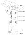
本発明の第1実施形態に係る耐震橋脚10は、図1に示すように、複数の柱材11と、隣り合う柱材11,11を連結するつなぎ部材12とから構成されており、各柱材11,11・・・は、基礎に立設している。この耐震橋脚10は、直上からの荷重を受ける耐震橋脚であって、1本の柱材11だけでは耐震橋脚10としての役割を果たさないが、複数の柱材11,11・・・を用いて、つなぎ部材12,12・・・により隣り合う柱材11を連結することで耐震橋脚10としての役割を果たす。
なお、本実施形態において、耐震橋脚10を構成する柱材11を4本用いた単橋脚形式の場合について説明する。
As shown in FIG. 1, the earthquake-
In the present embodiment, the case of a single pier type using four
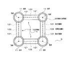
耐震橋脚10の柱材11が立設される基礎には鋼管杭Kが用いられ、鋼管杭Kは、地面に対して正四角形を形成する各頂点上(図4参照)に配置されている。また、各鋼管杭K,K・・・は、その上端部を地表に残して地中に設けられている(図1参照)。
したがって、各鋼管杭K,K・・・の上端部に立設される柱材11,11・・・も、地面に対して正四角形を形成する各頂点上に位置することとなる。
A steel pipe pile K is used as a foundation on which the
Therefore, the
柱材11は、図2に示すように、中空であって、長尺の鋼管材を用いており、例えば、杭として用いられている鋼管杭を用いることができる。この柱材11は、基礎である鋼管杭Kの上端部と接合することにより立設する。
ここで、鋼管杭Kと接合している柱材11の下端部(基部)に、コンクリートを充填(合成構造)することができる(図示せず)。これにより、各柱材11の耐震性を向上させることができる。
As shown in FIG. 2, the
Here, the lower end portion (base portion) of the
また、柱材11は、所定の長さの鋼製管材を軸方向に連設して用いることもできる。したがって、橋脚として必要となる高さに対応して、本発明の耐震橋脚10の高さを適宜変更することができるようになっている。
なお、この各柱材11の上部には梁材Hが設けられ、その梁材Hに橋桁材(図示せず)を架設することができるようになっている。
Further, the
A beam member H is provided on the top of each
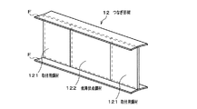
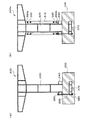
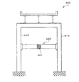
つなぎ部材12は、取付用鋼材121と低降伏点鋼材122とから構成されており、図3に示すように、柱材11(図1,図2参照)に取り付けられる両端部が取付用鋼材121となっており剛性の高い板状の鋼材が用いられ、また、この両端部の取付用鋼材121の間には低降伏点鋼材122が設けられ、各柱材11及び取付用鋼材121の降伏点よりも低い降伏点を有する板状の鋼材が用いられている。この低降伏点鋼材122は溶接により取付用鋼材121に接合される。
The connecting
低降伏点鋼材122の両端部に接合された取付用鋼材121と低降伏点鋼材122とは、I型鋼材のウェブとして用いられる。これにより、耐震橋脚10が受けるせん断力は、ウェブとなる両端部の取付用鋼材121と低降伏点鋼材122とが受け持つこととなる。また、ウェブとなる両端部の取付用鋼材121と低降伏点鋼材122との上部及び下部には低降伏点鋼材122よりも降伏点が高い鋼製のフランジF,Fが設けられる。
The mounting
このつなぎ部材12は、図2に示すように、隣り合う柱材11,11の間に配置され、つなぎ部材12の取付用鋼材121の柱材11側端部を柱材11に溶接又はボルト・ナット(図示せず)で取り付けられる。
As shown in FIG. 2, the connecting
ここで、つなぎ部材12は、柱材11の長さによって、地面Gの位置に対して、高さ方向に所定の間隔で、適宜、配置することができる。
Here, the connecting
図1に示すように、つなぎ材12が柱材に複数取り付けられている場合の各つなぎ材の取り付け間隔は、例えば、地面Gからの長さが30mである柱材11を用いた場合は、地面Gから高さ方向に10mの位置に第1のつなぎ部材12Aを取り付け、第1のつなぎ部材12Aを取り付けた位置から高さ方向上方に6mづつ2箇所に第2,第3のつなぎ部材12B,12Cを取り付けることができる。
As shown in FIG. 1, when a plurality of connecting
このように、地面Gに対して正四角形の各頂点に配置したそれぞれの柱材11,11・・・に、正四角形の4辺を形成するようにつなぎ部材12を隣り合う柱材11,11に取り付けて、4本の柱材11,11・・・を束ねることにより、単橋脚形式(橋脚が1基である)の耐震橋脚10を形成する。
In this way, the
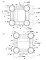
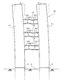
この耐震橋脚10において、地震が発生した場合のつなぎ部材12,12・・・の役割を説明する。図5は、図1のB矢視方向から耐震橋脚10を臨んだ場合の、耐震橋脚10が地震により揺れた場合の柱材11,11の上端部の変位を示す平面図であり、(a)は、西側に柱材11,11・・・の上端部が変位した場合を示す平面図であり、(b)は、北側に柱材11,11・・・の上端部が変位した場合を示す平面図である。図6は、耐震橋脚10の柱材11が撓んだ状態の一例を示す側面図である。
なお、方向を示す東,西,南,北は、図5の紙面上において、上方向を北、下方向を南、左方向を西、右方向を東、とする。
In this earthquake-
In the direction of east, west, south, and north, the upper direction is north, the lower direction is south, the left direction is west, and the right direction is east.
この耐震橋脚10は、東西側に揺れる地震が発生すると、各柱材11,11・・・は、鋼管杭Kと接合した下端部から東西側に反復するように曲げられる。このとき、各柱材11,11・・・が西側に曲げられた場合について説明すると、図5(a)に示すように、柱材11,11・・・が曲げられると、北側のつなぎ部材12の北西側の柱材11の取り付け位置と北東側の柱材11の取り付け位置とに相対変位が生じ、北側のつなぎ部材12がせん断力を受けることとなる。同様に、南側のつなぎ部材12の南西側の柱材11の取り付け位置と南東側の柱材11の取り付け位置とに相対変位が生じ、南側のつなぎ部材12がせん断力を受けることとなる。一方、西側のつなぎ部材12と東側のつなぎ部材12とには、せん断力の影響をほとんど受けることがない。
When this earthquake-
図6に示すように、北側のつなぎ部材12と南側のつなぎ部材12とがせん断力を受けると、柱材11,11・・・が倒壊に至る前に、北側、南側それぞれのつなぎ部材12,12の取付用鋼材121,121及びフランジF,F、さらに柱材11,11・・・よりも早く低降伏点鋼材122,122が降伏して柱材11,11・・・の倒壊を防ぐ。
As shown in FIG. 6, when the connecting
また、北側のつなぎ部材12の低降伏点鋼材122と南側のつなぎ部材12の低降伏点鋼材122とは、地震の規模により、北側、南側のつなぎ部材12,12の両方、又は、いずれか一方が降伏することにより柱材11,11・・・の倒壊を防ぐことができる。
したがって、つなぎ部材12の低降伏点鋼材122が地震力(地震エネルギ)を吸収することにより、低降伏点鋼材122が損傷することなく各柱材11及び取付用鋼材121よりも早く降伏し、各柱材11の倒壊を防ぐことができる。つまり、つなぎ部材12の低降伏点鋼材122が各柱材11の身代わりとなって降伏することで、各柱材11を保護することができる。
ここで、降伏とは、鋼材としての機能を有しつつ鋼材が塑性域に入った状態を示している。また、損傷とは、鋼材がその機能を果たせない状態となっていることを示している。
Further, the low yield
Therefore, when the low yield
Here, the yield indicates a state in which the steel material enters the plastic region while having a function as a steel material. Moreover, damage has shown that the steel material is in the state which cannot fulfill the function.
また、耐震橋脚10は、南北側に揺れる地震が発生すると、各柱材11,11・・・は、鋼管杭Kと取り付けた下端部から南北側に反復するように曲げられる。このとき、各柱材11,11・・・が北側に曲げられた場合について説明すると、図5(b)に示すように、柱材11,11・・・が曲げられると、西側のつなぎ部材12の北西側の柱材11の取り付け位置と南西側の柱材11の取り付け位置とに相対変位が生じ、西側のつなぎ部材12がせん断力を受けることとなる。同様に、東側のつなぎ部材12の北東側の柱材11の取り付け位置と南東側の柱材11の取り付け位置とに相対変位が生じ、東側のつなぎ部材12がせん断力を受けることとなる。一方、北側のつなぎ部材12と南側のつなぎ部材12とには、せん断力の影響をほとんど受けることがない。
Moreover, when the earthquake swaying on the north-south side occurs, the
西側のつなぎ部材12と東側のつなぎ部材12がせん断力を受けると、柱材11,11・・・が倒壊に至る前に、西側、東側それぞれのつなぎ部材12,12の取付用鋼材121,121及びフランジF,F、さらに柱材11,11・・・よりも早く低降伏点鋼材122,122が降伏して、柱材11,11・・・の倒壊を防ぐ。
When the connecting
また、西側のつなぎ部材12の低降伏点鋼材122と東側のつなぎ部材12の低降伏点鋼材122は、地震の規模により、西側、東側のつなぎ部材12,12の両方、又は、いずれか一方が降伏することにより柱材11,11・・・の倒壊を防ぐことができる。
Further, the low yield
また、耐震橋脚10は、図示しないが、北西−南東側や北東−南西側に揺れる地震が発生すると、各柱材11,11・・・は、鋼管杭Kと接合した下端部から北西−南東側や北東−南西側に反復するように曲げられ、北側,南側,西側,東側の各つなぎ部材12,12・・・がせん断力を受ける。
これらつなぎ部材12,12・・・は、せん断力を受けると、降伏点を超えない範囲で弾性変形するが、降伏点を超えると取付用鋼材121及びフランジF,柱材11よりも早く低降伏点鋼材122,122・・・が降伏して、柱材11,11・・・の倒壊を防ぐ。
Moreover, although the earthquake-
When the connecting
これにより、あらゆる方向で揺れる地震が発生しても、倒壊しない耐震橋脚10とすることができる。
Thereby, even if the earthquake which shakes in all directions occurs, it can be set as the earthquake-
また、地震により降伏した低降伏点鋼材122は、新たな低降伏点鋼材と取り替えることができる。地震により降伏した低降伏点鋼材122については、目視で確認することができるため、容易に降伏した低降伏点鋼材122を見つけることができる。降伏した低降伏点鋼材122は、つなぎ部材12の両端部の取付用鋼材121から切断されて取り外される。そして、新たな低降伏点鋼材を降伏した低降伏点鋼材122が取り外された位置に溶接によりつなぎ部材12の両端部の取付用鋼材121に接合される。
Moreover, the low yield
このように、耐震橋脚10を構成したので、建設コストの低コスト化を実現でき、不確定な方向に発生する地震の揺れにも確実に対応することができる。
As described above, since the earthquake-
(第2実施形態)
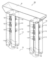
次に、本発明の耐震橋脚10をラーメン構造の橋脚の脚部として用いた場合について説明する。図7は、ラーメン構造の耐震橋脚の一例を示す斜視図である。
(Second Embodiment)
Next, the case where the earthquake-
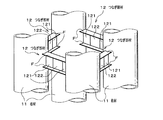
本発明の第2実施形態に係る耐震橋脚20は、図7に示すように、第1実施形態に係る耐震橋脚10を2基並べ、各柱材11,11・・・・に掛かるように梁材Hが横架され固定されたラーメン構造の耐震橋脚20となっている。
As shown in FIG. 7, the
このように構成されたラーメン構造の耐震橋脚20は、不確定な方向に揺れる地震が発生したとしても、前記のとおり、各耐震橋脚10,10が地震の揺れに対抗するので、隣り合う柱材11,11を連結するつなぎ部材12が、柱材11が倒壊する前に地震力(地震エネルギ)を吸収することにより降伏して、各耐震橋脚10,10の柱材11,11・・・を保護することができる。
As described above, the
このように、ラーメン構造の耐震橋脚20を構成したので、低コストを実現でき、不確定な方向に発生する地震の揺れにも対応することができる。
In this way, since the ramen-structured earthquake-
以上、本発明について、好適な実施形態の一例を説明した。しかし、本発明は、前記実施形態に限られず、前記の各構成要素については、本発明の趣旨を逸脱しない範囲で、適宜設計変更が可能である。 Heretofore, an example of a preferred embodiment has been described for the present invention. However, the present invention is not limited to the above-described embodiment, and the design of each of the above-described components can be appropriately changed without departing from the spirit of the present invention.
例えば、基礎は、鋼管杭のほかに、地中に埋設されるフーチングを用いることもできる。このフーチングは、例えば、コンクリート構造物であって、その上面が矩形形状になっており、地中に設けられた複数の鋼管杭により支持されている。このように支持されたフーチングの上面に柱材を、フーチングの上部に対して多角形を形成するように、その多角形の頂点上にそれぞれ配置し固定することもできる。
したがって、柱材を支持する基礎の種類に制限されることなく、柱材を基礎に立設することができる。
なお、柱材11,11・・・は、その下端部をフーチング内に埋設させて立設してもよい。この場合、柱材11の下端部には、外周面に沿ってスタッドを取り付けておく。これにより、スタッドが硬化したコンクリートに引っかかるので柱材11がフーチングから抜け出るのを防止することができる。
For example, a footing buried in the ground can be used for the foundation in addition to the steel pipe pile. The footing is, for example, a concrete structure, the upper surface of which is rectangular, and is supported by a plurality of steel pipe piles provided in the ground. It is also possible to place and fix the column material on the upper surface of the footing supported in this manner, so as to form a polygon with respect to the upper portion of the footing, respectively, on the vertex of the polygon.
Therefore, the pillar material can be erected on the foundation without being limited to the kind of foundation that supports the pillar material.
The
また、柱材の配置位置は正四角形に限られず、地面に対して三角形、角形(長方形)、五角形、六角形等、多角形となる各頂点上にしても良い。 In addition, the position of the column member is not limited to a regular square, and may be on each vertex of a polygon such as a triangle, a rectangle (rectangle), a pentagon, or a hexagon with respect to the ground.
また、柱材の長さ(耐震橋脚の高さ)に応じて、つなぎ部材を高さ方向に2段、4段、等、複数段設けても良い。このようにすることにより、耐震橋脚が高架橋の橋脚として用いられる場合であっても、不確定な方向に発生する地震の揺れにも対応することができる。 Moreover, according to the length of a pillar material (height of an earthquake-resistant pier), you may provide several steps, such as a 2 step | paragraph and 4 steps | paragraphs, in a height direction. By doing in this way, even if an earthquake-resistant bridge pier is used as a viaduct pier, it can respond to the shaking of the earthquake which occurs in an uncertain direction.
また、地面は傾斜していても良い。したがって、傾斜している地面に耐震橋脚を設ける場合は、傾斜した地面に対して多角形を描くように、その多角形の各頂点上に基礎としての鋼管杭を設置し、その各鋼管杭の外部に露出する端部に柱材の下端部を接合して、柱材を多角形の各頂点上に配置することができる。
このようにして設ける耐震橋脚は、例えば、法面に脚部を設置する高速道路等に架けられるラーメン橋脚の脚部として用いることができる。
Moreover, the ground may be inclined. Therefore, when installing seismic piers on sloping ground, install steel pipe piles as the foundation on each vertex of the polygon so that a polygon is drawn on the sloping ground. The column material can be disposed on each vertex of the polygon by joining the lower end of the column material to the end portion exposed to the outside.
The seismic pier provided in this way can be used, for example, as a leg part of a ramen pier that is hung on an expressway or the like in which a leg part is installed on a slope.
10 耐震橋脚
11 柱材
12,12A,12B,12C つなぎ部材
121 取付用鋼材
122 低降伏点鋼材
F フランジ
G 地面
K 鋼管杭(基礎)
10
Claims (3)
前記つなぎ部材が、前記柱材に取り付けられる両端部の取付用鋼材の間に低降伏点鋼材を備え、
前記柱材が鋼管材であり、
前記低降伏点鋼材の降伏点が前記取付用鋼材及び前記柱材の降伏点よりも低く設定されて構成されることを特徴とする耐震橋脚。 A plurality of pillars erected on the foundation, and a connecting member that connects the adjacent pillars;
The connecting member comprises a low yield point steel material between the steel materials for attachment at both ends attached to the column material,
The column material is a steel pipe material,
An earthquake-resistant bridge pier characterized in that a yield point of the low yield point steel material is set lower than a yield point of the mounting steel material and the column material.
Priority Applications (1)
| Application Number | Priority Date | Filing Date | Title |
|---|---|---|---|
| JP2004111863A JP2005299080A (en) | 2004-04-06 | 2004-04-06 | Earthquake-resistant bridge pier |
Applications Claiming Priority (1)
| Application Number | Priority Date | Filing Date | Title |
|---|---|---|---|
| JP2004111863A JP2005299080A (en) | 2004-04-06 | 2004-04-06 | Earthquake-resistant bridge pier |
Publications (1)
| Publication Number | Publication Date |
|---|---|
| JP2005299080A true JP2005299080A (en) | 2005-10-27 |
Family
ID=35330968
Family Applications (1)
| Application Number | Title | Priority Date | Filing Date |
|---|---|---|---|
| JP2004111863A Withdrawn JP2005299080A (en) | 2004-04-06 | 2004-04-06 | Earthquake-resistant bridge pier |
Country Status (1)
| Country | Link |
|---|---|
| JP (1) | JP2005299080A (en) |
Cited By (12)
| Publication number | Priority date | Publication date | Assignee | Title |
|---|---|---|---|---|
| JP2007205059A (en) * | 2006-02-02 | 2007-08-16 | Nippon Steel Corp | Connection structure of circular steel pipe column and H-section steel beam and pier using the connection structure |
| JP2008303598A (en) * | 2007-06-07 | 2008-12-18 | Nippon Steel Corp | Column base structure in multi-column type pier. |
| CN100453737C (en) * | 2007-06-15 | 2009-01-21 | 四川省交通厅公路规划勘察设计研究院 | Steel-pipe concrete assembled pier |
| CN103422445A (en) * | 2013-09-04 | 2013-12-04 | 中建六局土木工程有限公司 | Constructing method of high temporary bridge crossing river in extremely cold area |
| CN103526691A (en) * | 2013-10-31 | 2014-01-22 | 中铁二院工程集团有限责任公司 | Basic shock insulation structure for pier |
| JP2014029110A (en) * | 2012-07-06 | 2014-02-13 | Nippon Steel & Sumikin Engineering Co Ltd | Seismic control device, installation method for the same, and waveform plate |
| CN103643627A (en) * | 2013-12-20 | 2014-03-19 | 中铁二院工程集团有限责任公司 | Damping structure for continuous rigid frame pier with limited constraint |
| KR101437085B1 (en) * | 2012-12-13 | 2014-09-11 | (주)대우건설 | Modular pier bracing apparatus for improving earthquake-proof function |
| JP2017133223A (en) * | 2016-01-27 | 2017-08-03 | 三井住友建設株式会社 | Steel pipe joint, steel pipe well structure pier equipped with the same, and half precast concrete structure pier with joint |
| CN107642009A (en) * | 2017-10-16 | 2018-01-30 | 中铁第四勘察设计院集团有限公司 | A kind of suspension type monorail traffic supporting construction based on boundling concrete filled steel tube |
| KR101829579B1 (en) * | 2017-02-17 | 2018-02-14 | 임철수 | Bridge system with seismic resistance infrastructure |
| KR102864309B1 (en) * | 2024-10-16 | 2025-09-24 | 현대제철 주식회사 | Connecting Brace and Multi-Tubular Column Comprising the Same |
-
2004
- 2004-04-06 JP JP2004111863A patent/JP2005299080A/en not_active Withdrawn
Cited By (13)
| Publication number | Priority date | Publication date | Assignee | Title |
|---|---|---|---|---|
| JP2007205059A (en) * | 2006-02-02 | 2007-08-16 | Nippon Steel Corp | Connection structure of circular steel pipe column and H-section steel beam and pier using the connection structure |
| JP2008303598A (en) * | 2007-06-07 | 2008-12-18 | Nippon Steel Corp | Column base structure in multi-column type pier. |
| CN100453737C (en) * | 2007-06-15 | 2009-01-21 | 四川省交通厅公路规划勘察设计研究院 | Steel-pipe concrete assembled pier |
| JP2014029110A (en) * | 2012-07-06 | 2014-02-13 | Nippon Steel & Sumikin Engineering Co Ltd | Seismic control device, installation method for the same, and waveform plate |
| KR101437085B1 (en) * | 2012-12-13 | 2014-09-11 | (주)대우건설 | Modular pier bracing apparatus for improving earthquake-proof function |
| CN103422445A (en) * | 2013-09-04 | 2013-12-04 | 中建六局土木工程有限公司 | Constructing method of high temporary bridge crossing river in extremely cold area |
| CN103526691A (en) * | 2013-10-31 | 2014-01-22 | 中铁二院工程集团有限责任公司 | Basic shock insulation structure for pier |
| CN103643627A (en) * | 2013-12-20 | 2014-03-19 | 中铁二院工程集团有限责任公司 | Damping structure for continuous rigid frame pier with limited constraint |
| JP2017133223A (en) * | 2016-01-27 | 2017-08-03 | 三井住友建設株式会社 | Steel pipe joint, steel pipe well structure pier equipped with the same, and half precast concrete structure pier with joint |
| KR101829579B1 (en) * | 2017-02-17 | 2018-02-14 | 임철수 | Bridge system with seismic resistance infrastructure |
| CN107642009A (en) * | 2017-10-16 | 2018-01-30 | 中铁第四勘察设计院集团有限公司 | A kind of suspension type monorail traffic supporting construction based on boundling concrete filled steel tube |
| CN107642009B (en) * | 2017-10-16 | 2023-06-02 | 中铁第四勘察设计院集团有限公司 | Suspension type monorail traffic supporting structure based on bunched steel pipe concrete |
| KR102864309B1 (en) * | 2024-10-16 | 2025-09-24 | 현대제철 주식회사 | Connecting Brace and Multi-Tubular Column Comprising the Same |
Similar Documents
| Publication | Publication Date | Title |
|---|---|---|
| US7188452B2 (en) | Sleeved bracing useful in the construction of earthquake resistant structures | |
| CN106382041B (en) | A kind of assembled waves Self-resetting steel support structure system | |
| JP2005299080A (en) | Earthquake-resistant bridge pier | |
| JP2007023626A (en) | Vibration-controlled base-isolated structure | |
| JP2006077492A (en) | Earthquake resisting pier | |
| JP2001262774A (en) | Steel-concrete composite structural members | |
| JP4472726B2 (en) | Base-isolated building structure | |
| JP4408181B2 (en) | Seismic strength reinforcement method for bridges and piers | |
| JP2012057431A (en) | Structure for connecting pile and steel column | |
| JP2000240001A (en) | Overbridge | |
| JP5041758B2 (en) | Seismic isolation structure with artificial ground | |
| JP2005083136A (en) | Composite structure support | |
| JP6985037B2 (en) | Pier foundation structure | |
| JP2010222936A (en) | Rockfall-avalanche preventing fence | |
| JP6636747B2 (en) | Building damping structure | |
| JP3397220B2 (en) | Damping device | |
| JP3636924B2 (en) | Foundation structure | |
| JP2006316495A (en) | Foundation structure of bridge pier and its construction method | |
| JP4449595B2 (en) | Column-beam joint structure, method for constructing column-beam joint structure, method for constructing underground structure, and building | |
| JP4191357B2 (en) | Structure for preventing collapse of structures | |
| JP2832708B2 (en) | Anchor frame | |
| JP2004232205A (en) | Building support structure | |
| JP4432581B2 (en) | Building structure that can change floor height | |
| JP2003074019A (en) | Pedestal structure, and aseismatic reinforcement structure | |
| JP2000145200A (en) | Aspect-ratio vibration-isolation device |
Legal Events
| Date | Code | Title | Description |
|---|---|---|---|
| A621 | Written request for application examination |
Free format text: JAPANESE INTERMEDIATE CODE: A621 Effective date: 20070405 |
|
| A711 | Notification of change in applicant |
Free format text: JAPANESE INTERMEDIATE CODE: A712 Effective date: 20070518 |
|
| A521 | Written amendment |
Free format text: JAPANESE INTERMEDIATE CODE: A821 Effective date: 20070518 |
|
| A761 | Written withdrawal of application |
Effective date: 20070625 Free format text: JAPANESE INTERMEDIATE CODE: A761 |
|
| A521 | Written amendment |
Free format text: JAPANESE INTERMEDIATE CODE: A821 Effective date: 20070625 |