JP2005297903A - Temperature detecting device for vehicle and air conditioner for vehicle - Google Patents
Temperature detecting device for vehicle and air conditioner for vehicle Download PDFInfo
- Publication number
- JP2005297903A JP2005297903A JP2004120338A JP2004120338A JP2005297903A JP 2005297903 A JP2005297903 A JP 2005297903A JP 2004120338 A JP2004120338 A JP 2004120338A JP 2004120338 A JP2004120338 A JP 2004120338A JP 2005297903 A JP2005297903 A JP 2005297903A
- Authority
- JP
- Japan
- Prior art keywords
- vehicle
- air
- temperature
- sensor
- seat
- Prior art date
- Legal status (The legal status is an assumption and is not a legal conclusion. Google has not performed a legal analysis and makes no representation as to the accuracy of the status listed.)
- Pending
Links
Images


Landscapes
- Air-Conditioning For Vehicles (AREA)
Abstract
Description
本発明は、複数の検出素子をマトリックス状に配列されてなる非接触温度センサを備える車両用温度検出装置、および、非接触温度センサを備える車両用空調装置に関する。 The present invention relates to a vehicle temperature detection device including a non-contact temperature sensor in which a plurality of detection elements are arranged in a matrix, and a vehicle air conditioner including the non-contact temperature sensor.
従来、複数の検出素子をマトリックス状に配列されてなる非接触温度センサ(具体的には赤外線温度センサ)を用いて乗員表面温度を検出し、その検出される表面温度を用いて空調ユニットを制御して、車室内の空調制御を行う車両用空調装置が提案されている(例えば、特許文献1参照)。
ところで、本発明等が、上述の特許文献1に記載の車両用空調装置の検出範囲について鋭意検討したところ、次のような問題があることが分かった。 By the way, when this invention etc. earnestly examined about the detection range of the vehicle air conditioner of the above-mentioned patent document 1, it turned out that there exist the following problems.
すなわち、乗員の顔部の表面温度は、髪の長さ、眼鏡の有無、マスクの有無、帽子の有無などの条件により大きく変わる。このため、非接触温度センサとしてその検出視野内に乗員の顔部が入るように設定すると、上述の如く条件に応じてその検出温度が大きく変わるため、車室内の空調制御を適切に行うことができないといった問題がある。 That is, the surface temperature of the occupant's face varies greatly depending on conditions such as the length of the hair, the presence or absence of glasses, the presence or absence of a mask, and the presence or absence of a hat. For this reason, if the occupant's face is set to be within the detection field of view as a non-contact temperature sensor, the detected temperature varies greatly depending on the conditions as described above, so that air conditioning control in the passenger compartment can be performed appropriately. There is a problem that can not be.
また、本発明者等の検討によれば、複数の検出素子をマトリックス状(すなわち、長方形状)に配列するのではなく、乗員顔部を除外して乗員肩部など検温が必要な部位だけを検出するように、複数の検出素子を配列することも考えられるものの、検温が必要な部位に合わせて複数の検出素子を複雑な形状に配列することが必要であるので、製造が難く、歩留まりが悪いことが分かった。 Further, according to the study by the present inventors, instead of arranging a plurality of detection elements in a matrix (that is, a rectangular shape), only the part that requires temperature measurement, such as an occupant shoulder, is excluded. Although it is conceivable to arrange a plurality of detection elements so as to detect, since it is necessary to arrange a plurality of detection elements in a complicated shape according to the site where temperature measurement is required, it is difficult to manufacture and the yield is high. I found it bad.
そこで、本発明は、各検出素子をマトリックス状に配列されてなる非接触温度センサを備える車両用温度検出装置において、車室内の表面温度を適切に検出することを第1の目的とする。 Accordingly, a first object of the present invention is to appropriately detect the surface temperature in the passenger compartment in a vehicle temperature detection apparatus including a non-contact temperature sensor in which the detection elements are arranged in a matrix.
また、各検出素子をマトリックス状に配列されてなる非接触温度センサを備える車両用空調装置において、車室内の空調を適切に行うようにすることを第2の目的とする。 It is a second object of the vehicle air conditioner including a non-contact temperature sensor in which the detection elements are arranged in a matrix to appropriately air-condition the vehicle interior.
上記目的を達成するため、請求項1に記載の発明では、車室内の表面温度をそれぞれ非接触で検出する検出素子(Dir1〜Dir16)がマトリックス状に配列される非接触温度センサ(70)を備える車両用温度検出装置であって、
前記非接触温度センサはそのセンサ視野内に乗員の顔部がほとんど含まないように組み付けられていることを特徴とする車両用温度検出装置。
In order to achieve the above object, according to the first aspect of the present invention, there is provided a non-contact temperature sensor (70) in which detection elements (Dir1 to Dir16) for detecting the surface temperature of the vehicle interior in a non-contact manner are arranged in a matrix. A vehicle temperature detection device comprising:
The vehicle temperature detecting device, wherein the non-contact temperature sensor is assembled so that the face of the occupant is hardly included in the sensor visual field.
請求項1に記載の発明によれば、非接触温度センサはそのセンサ視野内に乗員の顔部がほとんど含まれないので、非接触温度センサの検出温度が、髪の長さ、眼鏡の有無、マスクの有無、帽子の有無などの条件により変わることがない。これに伴い、車室内の表面温度を適切に検出することができる。 According to the invention described in claim 1, since the non-contact temperature sensor includes almost no occupant's face in the sensor field of view, the detected temperature of the non-contact temperature sensor is the length of the hair, the presence or absence of glasses, It does not change depending on conditions such as the presence or absence of a mask or the presence or absence of a hat. Along with this, the surface temperature in the passenger compartment can be detected appropriately.
ここで、非接触温度センサの検出温度を空調制御に用いる場合には、請求項2に記載の発明のように、非接触温度センサとしてはそのセンサ視野内に少なくとも、前記乗員の太股、肩部のうち少なくとも一方を含むように組み付けられるようすることが必要である。 Here, when the detected temperature of the non-contact temperature sensor is used for air-conditioning control, the non-contact temperature sensor is at least in the sensor field of view as the non-contact temperature sensor, as shown in FIG. It is necessary to be assembled so as to include at least one of them.
請求項2に記載の発明によれば、非接触温度センサはそのセンサ視野内に乗員の顔部がほとんど含まないで、太股、肩部のうち少なくとも一方を含むように配置されるので、乗員の表面温度を適切に検出することができる。 According to the second aspect of the present invention, the non-contact temperature sensor is arranged so as not to include the occupant's face in the sensor field of view and to include at least one of the crotch and the shoulder. The surface temperature can be detected appropriately.
また、請求項3に記載の発明のように、前記非接触温度センサは二人の乗員の表面温度を検出するように組み付けられていれば、乗員一人に対して1つの非接触温度センサを用いる場合に比べて、低コストで車両用温度検出装置を構成することができる。 Moreover, if the said non-contact temperature sensor is assembled | attached so that the surface temperature of two passengers may be detected like invention of Claim 3, one non-contact temperature sensor is used with respect to one passenger. Compared to the case, the vehicle temperature detection device can be configured at low cost.
ここで、具体的には、請求項4に記載の発明のように、非接触温度センサは、前記二人の乗員の中間部に配置されて、車室内の天井側から前記二人の乗員の表面温度を検出するように配設してもよい。 Specifically, as in the invention described in claim 4, the non-contact temperature sensor is disposed in an intermediate part of the two passengers, and the two passengers are You may arrange | position so that surface temperature may be detected.
さらに、例えば、請求項5に記載の発明のように、車室内には、前記二人の乗員が着座する二つの座席が車両横方向に並んで配置されている場合には、非接触温度センサは、その前記車両横方向のセンサ視野角が、60°〜75°の間に設定されていることが必要である。 Further, for example, as in the invention described in claim 5, when two seats on which the two occupants are seated are arranged side by side in the vehicle lateral direction, the non-contact temperature sensor The sensor viewing angle in the lateral direction of the vehicle needs to be set between 60 ° and 75 °.
請求項6に記載の発明のように、非接触温度センサは、前記車室内の後部座席側の表面温度を検出するものである。 As in the sixth aspect of the invention, the non-contact temperature sensor detects a surface temperature on the rear seat side of the vehicle interior.
請求項7に記載の発明では、車室内の表面温度をそれぞれ非接触で検出する検出素子(Dir1〜Dir16)がマトリックス状に配列される非接触温度センサ(70)を備える車両用温度検出装置であって、
前記非接触温度センサはそのセンサ視野角は、60°〜75°の間に設定されていることを特徴とする。
In a seventh aspect of the invention, there is provided a vehicle temperature detecting device including a non-contact temperature sensor (70) in which detection elements (Dir1 to Dir16) for detecting the surface temperature of the vehicle interior in a non-contact manner are arranged in a matrix. There,
The non-contact temperature sensor has a sensor viewing angle set between 60 ° and 75 °.
ここで、請求項8に記載の発明のように、前記非接触温度センサは、二人の乗員の表面温度を検出するように組み付けられていてもよい。
Here, as in the invention described in
また、請求項9に記載の発明のように、非接触温度センサは、前記二人の乗員の中間部に配置されて、車室内の天井側から前記二人の乗員の表面温度を検出するようにしてもよい。 According to a ninth aspect of the present invention, the non-contact temperature sensor is disposed in an intermediate part of the two passengers so as to detect the surface temperature of the two passengers from the ceiling side in the vehicle interior. It may be.
さらに、請求項10に記載の発明のように、前記車室内には、前記二人の乗員が着座する二つの座席が所定方向に並んで配置されており、
前記センサ視野角は、前記二つの座席が並べられる所定方向(図3(b)中Y2)の角度である。
Furthermore, as in the invention according to
The sensor viewing angle is an angle in a predetermined direction (Y2 in FIG. 3B) in which the two seats are arranged.
ところで、本発明者等の検討によれば、乗員に向けて非接触温度センサを配置すると、乗員によっては、“非接触温度センサによって見られている”(或いは、非接触温度センサによって監視されている)といった違和感を感じることがあることが分かった。 By the way, according to the study by the present inventors, when a non-contact temperature sensor is arranged toward the occupant, depending on the occupant, it is “seen by the non-contact temperature sensor” (or monitored by the non-contact temperature sensor. It was found that there may be a sense of discomfort.
これに対して、請求項11に記載の発明では、請求項3ないし5、8ないし10のいずれか1つに記載の車両用温度検出装置において、前記車室内には、前記二人の乗員が着座する二つの座席が並んで配置されており、前記非接触温度センサは、前記二つの座席のうち乗員が座る頻度の低い座席の方に向けて配置されていることを特徴する。
On the other hand, in the invention according to
請求項12に記載の発明によれば、乗員が“非接触温度センサの検出面が向けられている座席”に座る確率が少なくなるので、乗員にとっては、“非接触温度センサによって見られている”といった違和感を感じる確率が少なくなる。 According to the twelfth aspect of the invention, since the probability that the occupant sits on the “seat to which the detection surface of the non-contact temperature sensor is directed” is reduced, the occupant is seen by the “non-contact temperature sensor”. The probability of feeling uncomfortable is reduced.
請求項13に記載の発明では、車室内を空調する空調手段(6)と、
前記車室内の表面温度をそれぞれ非接触で検出する検出素子(Dir1〜Dir16)がマトリックス状に配列される非接触温度センサ(70)と、
前記非接触温度センサの検出温度に基づいて前記空調手段を制御する制御手段(8)と、を備える車両用空調装置であって、
前記非接触温度センサはそのセンサ視野内に乗員の顔部がほとんど含まないように組み付けられていることを特徴とする車両用空調装置。
In invention of Claim 13, the air-conditioning means (6) which air-conditions a vehicle interior,
A non-contact temperature sensor (70) in which detection elements (Dir1 to Dir16) for detecting the surface temperature of the vehicle interior in a non-contact manner are arranged in a matrix;
A vehicle air conditioner comprising: control means (8) for controlling the air conditioning means based on a temperature detected by the non-contact temperature sensor;
The vehicle air conditioner, wherein the non-contact temperature sensor is assembled so that an occupant's face is hardly included in the sensor visual field.
請求項13に記載の発明によれば、非接触温度センサはそのセンサ視野内に乗員の顔部がほとんど含まれないので、非接触温度センサの検出温度が、髪の長さ、眼鏡の有無、マスクの有無、帽子の有無などの条件により変わることがない。これに伴い、車室内の表面温度を適切に検出することができるので、この検出された表面温度を用いて空調手段を制御することにより、車室内の空調を適切に行うことができる。 According to the invention of claim 13, since the non-contact temperature sensor includes almost no occupant's face in the sensor field of view, the detected temperature of the non-contact temperature sensor is the length of the hair, the presence or absence of glasses, It does not change depending on conditions such as the presence or absence of a mask or the presence or absence of a hat. Accordingly, since the surface temperature in the vehicle interior can be detected appropriately, the air conditioning in the vehicle interior can be appropriately performed by controlling the air conditioning means using the detected surface temperature.
ここで、車室内の空調を行うに際して、請求項13に記載の発明のように、前記非接触温度センサはそのセンサ視野内に少なくとも前記乗員の太股、肩部のうち少なくとも一方を含むように組み付けられていることが必要である。 Here, when air-conditioning the vehicle interior, as in the invention according to claim 13, the non-contact temperature sensor is assembled so that at least one of the occupant's thighs and shoulders is included in the sensor field of view. It is necessary to be done.
また、請求項14に記載の発明のように、非接触温度センサは二人の乗員の表面温度を検出するように組み付けられていれば、乗員一人に対して1つの非接触温度センサを用いる場合に比べて、低コストで車両用温度検出装置を構成することができる。 Further, as in the invention described in claim 14, when the non-contact temperature sensor is assembled so as to detect the surface temperature of two occupants, one non-contact temperature sensor is used for one occupant. Compared to the above, the vehicle temperature detection device can be configured at low cost.
ここで、請求項15に記載の発明のように、前記非接触温度センサは、前記二人の乗員の中間部に配置されて、車室内の天井側から前記二人の乗員の表面温度を検出するようにしてもよい。 Here, as in the invention described in claim 15, the non-contact temperature sensor is disposed in an intermediate part of the two passengers and detects the surface temperature of the two passengers from the ceiling side in the passenger compartment. You may make it do.
また、請求項16に記載の発明によれば、前記車室内には、前記二人の乗員が着座する二つの座席が車両横方向に並んで配置されている場合に、前記非接触温度センサはその前記車両横方向のセンサ視野角が、60°〜75°の間に設定されていることを特徴とする。 According to a sixteenth aspect of the present invention, when the two seats on which the two passengers are seated are arranged side by side in the vehicle lateral direction, the non-contact temperature sensor is The sensor lateral angle in the vehicle lateral direction is set between 60 ° and 75 °.
なお、上記各手段の括弧内の符号は、後述する実施形態に記載の具体的手段との対応関係を示すものである。 In addition, the code | symbol in the bracket | parenthesis of each said means shows the correspondence with the specific means as described in embodiment mentioned later.
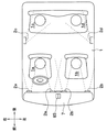
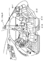
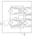
本発明の第1実施形態について図面を参照して説明する。図1は本実施形態による車両用空調装置の室内空調ユニット部の吹出口配置状態を示す平面概要図、図2は室内空調ユニット部および制御ブロックを含む全体構成図である。 A first embodiment of the present invention will be described with reference to the drawings. FIG. 1 is a schematic plan view showing an air outlet arrangement state of an indoor air conditioning unit of the vehicle air conditioner according to this embodiment, and FIG. 2 is an overall configuration diagram including the indoor air conditioning unit and a control block.
本第1実施形態は、車室内1の前後左右の計4つの空調ゾーン1a、1b、1c、1dをそれぞれ独立して空調制御する。図1、図2は右ハンドル車の場合を示しており、上記空調ゾーン1a〜1dをより具体的に説明すると、空調ゾーン1aは、前席空調ゾーンのうち右側、すなわち、運転席側に位置する。空調ゾーン1bは、前席空調ゾーンのうち左側、すなわち、助手席側に位置する。
In the first embodiment, a total of four air-
そして、空調ゾーン1cは、後席空調ゾーンのうち右側窓寄りに位置し、空調ゾーン1dは、後席空調ゾーンのうち左側窓寄りに位置する。なお、図1中の前後左右の各矢印は、車両搭載時における前後左右の方向を示す。
The
車両用空調装置の室内空調ユニット部は空調手段としての前席用空調ユニット5と後席用空調ユニット6とから構成されている。前席用空調ユニット5は、前席左右の空調ゾーン1a、1bのそれぞれの空調状態(例えば、空気温度)を独立して調整するためのものであり、後席用空調ユニット6は、後席左右の空調ゾーン1c、1dのそれぞれの空調状態を独立して調整するためのものである。
The indoor air conditioning unit of the vehicle air conditioner is composed of a front seat air conditioning unit 5 and a rear seat
前席用空調ユニット5は、車室内1の最前部の計器盤7の内側に配置されており、後席用空調ユニット6は、車室内1の最後方に配置されている。前席用空調ユニット5は、車室内1の前席側に空気を送風するためのダクト50を備えている。このダクト50の最上流部には、車室内1から内気を導入するための内気導入口50aおよび車室外から外気を導入するための外気導入口50bが設けられている。
The front seat air conditioning unit 5 is disposed inside the front instrument panel 7 of the vehicle interior 1, and the rear seat
さらに、ダクト50には、外気導入口50bおよび内気導入口50aを選択的に開閉する内外気切替ドア51が設けられており、この内外気切替ドア51には、駆動手段としてのサーボモータ510aが連結されている。
Further, the
また、ダクト50内のうち外気導入口50bおよび内気導入口50aの空気下流側には、車室内1に向けて吹き出される空気流を発生させる遠心式送風機52が設けられている。遠心式送風機52は、遠心式羽根車およびこの羽根車を回転させるブロワモータ52aにより構成されている。なお、図2において、この羽根車は図の簡略化のため軸流式羽根車を示しているが、実際は遠心式の羽根車が使用されている。
A
さらに、ダクト50内にて遠心式送風機52の空気下流側には、空気を冷却する空気冷却手段としてのエバポレータ53が設けられており、さらに、このエバポレータ53の空気下流側には、空気加熱手段としてのヒータコア54が設けられている。
Further, an
そして、ダクト50内のうちエバポレータ53の空気下流側には仕切り板57が設けられており、この仕切り板57により、ダクト50内の空気通路を車両左右両側の2つの通路、すなわち、運転席側通路50cと助手席側通路50dとに仕切っている。
A
運転席側通路50cのうちヒータコア54の側方には、バイパス通路51aが形成されており、バイパス通路51aは、ヒータコア54に対してエバポレータ53により冷却された冷風をバイパスさせる。
A
また、助手席側通路50dのうちヒータコア54の側方には、バイパス通路51bが形成されており、バイパス通路51bは、ヒータコア54に対してエバポレータ53により冷却された冷風をバイパスさせる。
Further, a
運転席側通路50cおよび助手席側通路50dにおいてヒータコア54の空気上流側に、それぞれ、エアミックスドア55a、55bが独立に操作可能に設けられている。運転席側のエアミックスドア55aは、その開度により、運転席側通路50cを流通する冷風のうちヒータコア54を通る量(温風量)とバイパス通路51aを通る量(冷風量)との比を調整して、前席運転席側の空調ゾーン1aへの吹出空気温度を調整する。
In the driver
また、助手席側のエアミックスドア55bは、その開度により、助手席側通路50dを流通する冷風のうちヒータコア54を通る量(温風量)とバイパス通路51bを通る量(冷風量)との比を調整して、前席助手席側の空調ゾーン1bへの吹出空気温度を調整する。
Further, the
なお、前席左右のエアミックスドア55a、55bには、駆動手段としてのサーボモータ550a、550bがそれぞれ連結されており、エアミックスドア55a、55bの開度は、サーボモータ550a、550bによって、それぞれ独立に調整される。
In addition,
エバポレータ53は、図示しないコンプレッサ、凝縮器、受液器、減圧器とともに、周知の冷凍サイクルを構成している低圧側の冷却用熱交換器である。このエバポレータ53は、ダクト50内を流れる空気から低圧側冷媒が蒸発潜熱を吸熱して蒸発することにより、ダクト50内の空気を冷却する。なお、冷凍サイクルのコンプレッサは、車両エンジンに電磁クラッチ(図示しない)を介して連結され、電磁クラッチを断続制御することによって駆動停止制御される。
The
ヒータコア54は、車両エンジンからの温水(エンジン冷却水)を熱源とする加熱用熱交換器であり、このヒータコア54は蒸発器53通過後の空気を加熱する。
The
運転席側通路50cおよび助手席側通路50dのうちヒータコア54の空気下流側(最下流部)には、運転席側フェイス吹出口2aおよび助手席側フェイス吹出口2bが設けられている。
Of the driver
運転席側フェイス吹出口2aは、運転席側通路50cから運転席に着座する運転席乗員の上半身に向けて空気を吹き出す。また、助手席側フェイス吹出口2bは、助手席側通路50dから助手席に着座する助手席乗員の上半身に向けて空気を吹き出す。
The driver-seat-
さらに、運転席側通路50cおよび助手席側通路50dのうち運転席側フェイス吹出口2aおよび助手席側フェイス吹出口2bの各空気上流部には、それぞれ、運転席側フェイス吹出口2aを開閉する吹出口切替ドア56aおよび助手席側フェイス吹出口2bを開閉する吹出口切替ドア56bが設けられている。これら吹出口切替ドア56aおよび56bは、それぞれ駆動手段としての運転席側のサーボモータ560a、および助手席側のサーボモータ560bによって、開閉駆動される。
Furthermore, the driver's seat
なお、運転席側フェイス吹出口2aと助手席側フェイス吹出口2bは、具体的には図1に示すようにそれぞれ、計器盤7の左右方向の中央部寄り部位に位置するセンターフェイス吹出口と計器盤7の左右方向の両端部付近に位置するサイドフェイス吹出口とに分けて配置される。
The driver's seat-
また、図1、図2には図示していないが、運転席側通路50cの最下流部には、上記運転席側フェイス吹出口2aの他に、運転席側フット吹出口および運転席側デフロスタ吹出口が設けられている。運転席側フット吹出口は運転席側通路50cから運転者の下半身に空気を吹き出す。運転席側デフロスタ吹出口は運転席側通路50cからフロントガラスの内表面のうち運転席側領域に空気を吹き出す。
Although not shown in FIGS. 1 and 2, in addition to the driver-seat-
助手席側通路50dの最下流部には、上記助手席側フェイス吹出口2bの他に、助手席側フット吹出口および助手席側デフロスタ吹出口が設けられている。助手席側フット吹出口は助手席側通路50dから助手席乗員の下半身に空気を吹き出す。助手席側デフロスタ吹出口は助手席側通路50dからフロントガラスの内表面のうち助手席側領域に空気を吹き出す。
In the most downstream portion of the passenger
そして、運転席側通路50cにおいて運転席側フット吹出口および運転席側デフロスタ吹出口の空気上流部には、それぞれの吹出口を開閉する吹出口切替ドア(図示せず)が設けられている。そして、これら運転席側のフェイス、フットおよびデフロスタの各吹出口切替ドアは、上述した運転席側のサーボモータ560aにより連動して開閉駆動される。
In the driver
また、助手席側通路50dにおいて助手席側フット吹出口および助手席側デフロスタ吹出口の空気上流部には、それぞれの吹出口を開閉する吹出口切替ドア(図示せず)が設けられている。そして、これら助手席側のフェイス、フットおよびデフロスタの各吹出口切替ドアは、上述した助手席側のサーボモータ560bにより連動して開閉駆動される。
Further, in the passenger
後席用空調ユニット6は、車室内1に送風するためのダクト60を備えている。このダクト60内の最上流部には、車室内1から内気導入口60aを通して内気のみを導入する内気導入ダクト60bが接続されている。
The rear seat
内気導入ダクト60bの空気下流側には、車室内1に向けて吹き出される空気流を発生させる遠心式送風機62が設けられている。遠心式送風機62は、遠心式羽根車およびこの羽根車を回転させるブロワモータ62aにより構成されている。なお、この羽根車も図2において、上記と同様、図の簡略化のため軸流式羽根車を示しているが、実際は遠心式の羽根車が使用されている。
A
さらに、ダクト60内において遠心式送風機62の空気下流側には、空気を冷却する空気冷却手段としてのエバポレータ63が設けられており、このエバポレータ63の空気下流側には、空気を加熱する空気加熱手段としてのヒータコア64が設けられている。
Further, an
そして、ダクト60内のうちエバポレータ63の下流部分には仕切り板67が設けられており、この仕切り板67により、ダクト60内の空気通路を車両左右両側の2つの通路、すなわち、後席右側通路(後席運転席側通路)60cと後席左側通路(後席助手席側通路)60dとに仕切っている。
A
後席右側通路60cのうちヒータコア64の側方には、バイパス通路61aが形成されており、バイパス通路61aは、ヒータコア64に対してエバポレータ63により冷却された冷風をバイパスさせる。
A
また、後席左側通路60dのうちヒータコア64の側方には、バイパス通路61bが形成されており、バイパス通路61bは、ヒータコア64に対してエバポレータ63により冷却された冷風をバイパスさせる。
Further, a
後席右側通路60cおよび後席左側通路60dにおいてヒータコア64の空気上流側には、それぞれエアミックスドア65a、65bが独立に操作可能に設けられている。後席右側のエアミックスドア65aは、その開度により、後席右側通路60cを流通する冷風のうちヒータコア64を通る量(温風量)とバイパス通路61aとを通る量(冷風量)との比を調整して、後席右側の空調ゾーン1cへの吹出空気温度を調整する。
In the rear seat
また、後席左側のエアミックスドア65bは、その開度により、後席左側通路60dを通過する冷風のうちヒータコア64を通る量(温風量)とバイパス通路61bを通る量(冷風量)との比を調整して、後席左側の空調ゾーン1dへの吹出空気温度を調整する。
Further, the
そして、後席右側および後席左側のエアミックスドア65a、65bには、駆動手段としてのサーボモータ650a、650bがそれぞれ連結されており、後席右側および後席左側のエアミックスドア65a、65bの開度は、サーボモータ650a、650bによって、それぞれ独立に調整される。
エバポレータ63は、上述した周知の冷凍サイクルにおいて前席側のエバポレータ53に対して並列的に配管結合される冷却用熱交換器である。
The
また、ヒータコア64は、車両エンジンからの温水(エンジン冷却水)を熱源とする加熱用熱交換器であり、ヒータコア64は、温水回路において前席側のヒータコア54に対し並列的に接続され、エバポレータ63通過後の空気を加熱する。
The
ダクト60内の後席右側通路60cのうちヒータコア64の空気下流側(最下流部)には、後席右側フェイス吹出口2cが設けられている。後席右側フェイス吹出口2cは、後席右側通路60cから後席の右側(すなわち、後席運転席側)に着座する乗員(以下、後席右側乗員という)の上半身に向けて空気を吹き出す。
A rear seat
また、ダクト60内の後席左側通路60dのうちヒータコア64の空気下流側(最下流部)には、後席左側フェイス吹出口2dが設けられている。後席左側フェイス吹出口2dは、後席左側通路60dから後席の左側(すなわち、後席助手席側)に着座する乗員(以下、後席左側乗員という)の上半身に向けて空気を吹き出す。
In addition, a rear seat left
ここで、後席左右の各フェイス吹出口2c、2dの空気上流部には、それぞれ吹出口切替ドア66a、66bが設けられ、後席左右の各フェイス吹出口2c、2dを開閉するようになっている。この後席左右の吹出口切替ドア66a、66bは、駆動手段としてのサーボモータ660a、660bによって開閉駆動される。
Here, air
そして、図1、図2には図示しないが、後席右側通路60cの最下流部には、後席右側フェイス吹出口2cの他に後席右側フット吹出口が設けられている。この後席右側フット吹出口は、後席右側通路60cから空気を後席右側乗員の下半身に向けて吹き出す。
Although not shown in FIGS. 1 and 2, a rear seat right foot outlet is provided in the most downstream portion of the rear seat
同様に、後席左側通路60dの最下流部には、後席左側フェイス吹出口2dの他に後席左側フット吹出口が設けられている。この後席左側フット吹出口は、後席左側通路60dから空気を後席左側乗員の下半身に向けて吹き出す。
Similarly, a rear seat left foot outlet is provided in the most downstream portion of the rear seat left
この後席左右の各フット吹出口の空気上流部には、それぞれ吹出口切替ドア(図示せず)が設けられており、この後席左右の各吹出口切替ドアは、上記サーボモータ660c、660dによってそれぞれ開閉駆動される。 Air outlet switching doors (not shown) are provided in the air upstream portions of the left and right foot outlets of the rear seat, and the servo motors 660c and 660d are provided at the outlet right and left rear door switching doors. Are driven to open and close respectively.
制御手段(空調制御装置)としてのエアコンECU8の入力側には、外気温度センサ81、冷却水温度センサ82、日射センサ83、内気温度センサ84および蒸発器温度センサ86、87が接続されている。
An outside air temperature sensor 81, a cooling water temperature sensor 82, a
外気温度センサ81は、車室外温度を検出しその検出温度に応じた外気温度信号TamdispをエアコンECU8に出力する。冷却水温度センサ82は、エンジンの冷却水(すなわち温水)の温度を検出しその検出温度に応じた冷却水温度信号TwをエアコンECU8に出力する。
The outside air temperature sensor 81 detects the outside temperature of the passenger compartment and outputs an outside air temperature signal Tamdisp corresponding to the detected temperature to the
日射センサ83は、フロントウインドウの内側にて車両左右方向の略中央部分に配置された周知の2素子(2D)タイプの日射センサであり、車室内の運転席側空調ゾーン1aに入射される日射量と助手席側空調ゾーン1bに入射される日射量とを検出し、それら検出した各日射量に応じた日射量信号TsDrおよびTsPaをエアコンECU8に出力する。
The
内気温度センサ84は、車室内の空調ゾーン1a、1b(前席側空調領域)の空気温度を検出しその検出温度に応じた内気温度信号TrFrをエアコンECU8に出力する。蒸発器温度センサ86は、エバポレータ53の吹出空気温度を検出しその検出温度に応じた蒸発器吹出温度信号TeFrをエアコンECU8に出力するもので、蒸発器温度センサ87は、エバポレータ63の吹出空気温度を検出しその検出温度に応じた蒸発器吹出温度信号TeRrをエアコンECU8に出力する。
The inside
また、エアコンECU8には、空調ゾーン1a、1b、1c、1dのそれぞれの希望温度FrTsetDr、FrTsetPa、RrTsetDr、RrTsetPaが乗員により設定される温度設定スイッチ9、10、11、12が接続されている。そして、温度設定スイッチ9、10、11、12のそれぞれ近傍には、希望温度等の設定内容を表示する報知手段(表示手段)としてのディスプレイ9a、10a、11a、12aが備えられている。ディスプレイ9a、10a、11a、12aは、それぞれ座席毎に、その車両前側にて乗員に向けて配置されている。
The
さらに、エアコンECU8には、後席右側の空調ゾーン1cおよび後席左側の空調ゾーン1dのそれぞれの表面温度を検出するための非接触温度センサとしての赤外線温度センサ(以下、IRセンサ70という)が接続されている。ここで、IRセンサ70としては、入力される赤外線量の変化に対応した起電力変化を温度変化として検出するサーモパイル型検出素子が用いられている。
Further, the
次に、IRセンサの配置およびその検出範囲について図3〜図7を用いて説明する。 Next, the arrangement and detection range of the IR sensor will be described with reference to FIGS.
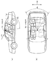
すなわち、IRセンサ70は、図3、図4(主に図3を参照)に示すように、車室内天井にて中央部、すなわち、後席右側座席および後席左側座席の間にて配置され、その検出面が図3中矢印Y1の如く、やや後方斜めに向けて配置されている。ここで、IRセンサ70は、後述するように、後席右側座席側の表面温度、および、後席左側座席側の表面温度の双方を検出するものである。
That is, as shown in FIGS. 3 and 4 (mainly refer to FIG. 3), the
例えば、IRセンサ70において矢印Y2に示す車幅方向(車両横方向)のセンサ視野角θsは、60°〜75°に設定されている。例えば、IRセンサ70は、車両ほぼ中央部の天井部に配置されており、具体的には、IRセンサ70は、乗員頭から150mmで、さらに車両前方に500mmの箇所に配置されている。
For example, in the
なお、車幅方向(車両横方向)は、請求項に記載の「二つの座席が並べられる所定方向」に相当する。このため、IRセンサ70としては、その視野内に、右側座席および左側座席の双方の乗員顔部を除いて、右側座席および左側座席側の双方の乗員の太股、肩部など必要な部位を含めるように設定されている。
The vehicle width direction (vehicle lateral direction) corresponds to “a predetermined direction in which two seats are arranged” described in the claims. For this reason, the
一方、IRセンサ70において前後方向向(車両縦方向)のセンサ視野角θtは、60°〜75°に設定されている。このため、IRセンサ70は、その視野内に、右側座席および左側座席の乗員顔部を除いて、右側座席側および左側座席側の乗員の太股部からリアトレイまでの必要な部位を含めるように設定されている。
On the other hand, in the
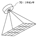
以下、IRセンサ70の構成について図5を用いて説明する。IRセンサ70は、図5に示すように、検知部71を有しており、検知部71は、基板71a、この基板71a上に設置されるセンサチップ72、および、このセンサチップ72を覆うように配設される赤外線吸収膜73を備えている。検知部71は、台座71c上に配置されるとともに、カップ状のケース71bによって覆われている。ケース71bの底部には、四角形の窓71dがあけられ、この窓71dにはレンズ71eが填め込まれている。また、赤外線吸収膜73は、空調ゾーン1c、1dの各検温対象物からレンズ71eを通して入射される赤外線を吸収して熱に変換する役割を果たす。
Hereinafter, the configuration of the
センサチップ72上には、16個の熱電対部Dir1〜Dr16が、4×4のマトッリクス状に配列されており、これらの熱電対部Dir1〜Dir12は、それぞれ、赤外線吸収膜73から発生する熱を電圧(電気エネルギー)に、それぞれ、変換する温度検出素子である。なお、熱電対部Dir1〜Dr16が請求項に記載の「検出素子」に相当する。
On the
図5、図6、図7はIRセンサ70の被検温範囲を示す図である。なお、図5中の符号Dir1〜Dir4は、熱電対部Dir1〜Dir4の被検温範囲を示し、図6、図7中の符号Dir1、Dir4は、熱電対部Dir1、Dir4の被検温範囲を示す。
5, 6, and 7 are diagrams showing the temperature range to be measured of the
先ず、熱電対部Dir1の被検温範囲は、リアトレイの右側領域に設定され、熱電対部Dir2の被検温範囲は、後席右側座席の乗員の肩部に設定され、熱電対部Dir3、の被検温範囲は、後席右側座席の乗員の腰部に設定され、熱電対部Dir4の被検温範囲は、後席右側座席の乗員の太股に設定される。なお、熱電対部Dir5〜Dir8の被検温範囲は、後席右側座席の車幅方向中央部側の領域に設定される。 First, the test temperature range of the thermocouple part Dir1 is set in the right region of the rear tray, the test temperature range of the thermocouple part Dir2 is set in the shoulder of the occupant of the right seat of the rear seat, and the test temperature range of the thermocouple part Dir3 is set. The temperature detection range is set at the lumbar region of the occupant in the right seat at the rear seat, and the temperature detection range of the thermocouple part Dir4 is set at the thigh of the occupant at the right seat at the rear seat. It should be noted that the test temperature range of the thermocouple portions Dir5 to Dir8 is set in a region on the vehicle width direction center portion side of the rear right seat.
ここで、リアトレイは、リアウンドウから入射される日射、冷射を受けるため、熱電対部Dir1は、後席右側座席の日射、冷射を示す温度を検出することができる。乗員の肩部、腰部、太股は、車室内の空気温度の影響を強く受けるため、熱電対部Dir2〜Dir4は、後席右側座席の車室内の空気温度を示す温度を検出することができる。 Here, since the rear tray receives solar radiation and cooling incident from the rear window, the thermocouple part Dir1 can detect a temperature indicating solar radiation and cooling of the right seat of the rear seat. Since the occupant's shoulder, waist, and thigh are strongly affected by the air temperature in the passenger compartment, the thermocouple parts Dir2 to Dir4 can detect the temperature indicating the air temperature in the passenger compartment of the right seat at the rear seat.
一方、熱電対部Dir9〜Dir16の被検温範囲は、熱電対部Dir1〜Dir8による被検温範囲と、車両左右の中央線について線対称の関係にあるので、図6においては省略している。 On the other hand, the test temperature range of the thermocouple parts Dir9 to Dir16 is axisymmetric with respect to the test temperature range of the thermocouple parts Dir1 to Dir8 with respect to the center line on the left and right sides of the vehicle, and is not shown in FIG.
すなわち、熱電対部Dir13の被検温範囲は、リアトレイの左側領域に設定され、熱電対部Dir14の被検温範囲は、後席左側座席の乗員の肩部に設定され、熱電対部Dir115の被検温範囲は、後席左側座席の乗員の腰部に設定され、熱電対部Dir16の被検温範囲は、後席左側座席の乗員の太股に設定される。なお、熱電対部Dir9〜Dir12の被検温範囲は、後席左側座席の車幅方向中央部側の領域に設定される。 That is, the test temperature range of the thermocouple part Dir13 is set in the left region of the rear tray, the test temperature range of the thermocouple part Dir14 is set in the shoulder of the passenger in the left seat of the rear seat, and the test temperature of the thermocouple part Dir115. The range is set to the waist of the occupant of the left seat on the rear seat, and the temperature range to be examined of the thermocouple Dir16 is set to the thigh of the occupant of the left seat of the rear seat. It should be noted that the test temperature range of the thermocouple parts Dir9 to Dir12 is set to a region on the vehicle width direction center portion side of the rear left seat.
一方、エアコンECU8は、アナログ/デジタル変換器、マイクロコンピュータ等を有して構成される周知のものであり、IRセンサ70、日射センサ83、各温度センサ81、82、84、86、87および温度設定スイッチ9、10、11、12からそれぞれ出力される出力信号は、アナログ/デジタル変換器によりアナログ/デジタル変換されてマイクロコンピュータにそれぞれ入力されるように構成されている。
On the other hand, the
マイクロコンピュータは、ROM、RAMなどのメモリ、およびCPU(中央演算装置)等から構成される周知のもので、イグニッションスイッチがオンされたときに、図示しないバッテリから電力供給される。 The microcomputer is a well-known computer composed of a memory such as a ROM and a RAM, a CPU (Central Processing Unit), and the like, and is supplied with power from a battery (not shown) when an ignition switch is turned on.
次に、上記構成において本第1実施形態の作動を図8〜図11に基づいて説明する。 Next, the operation of the first embodiment in the above configuration will be described with reference to FIGS.
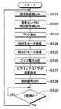
エアコンECU8は、電源が投入されると、メモリに記憶された制御プログラム(コンピュータプログラム)がスタートして、図8に示すフローチャートにしたがって空調制御処理を実行する。なお、以下に、前席空調処理および後席空調処理を分けて図8を参照して説明する。図8は各空調処理の内容を示している。
When the power is turned on, the
(前席空調処理)
まず、温度設定スイッチ9、10から設定温度信号FrTsetDr、FrTsetPaを読み込むとともに(ステップS121)、外気温度センサ81及び日射センサ83から外気温度信号Tamdisp、日射量信号TsDr、TsPaを読み込むとともに、内気温度センサ84から内気温度TrFrを読み込む(ステップS122)。
(Front seat air conditioning)
First, the set temperature signals FrTsetDr and FrTsetPa are read from the temperature setting switches 9 and 10 (step S121), the outside air temperature signal Tamdisp and the solar radiation amount signals TsDr and TsPa are read from the outside air temperature sensor 81 and the
そして、設定温度信号FrTsetDr、外気温信号Tam、日射量信号TsDr、内気温度信号TrFrを数式1に代入して、車室内に吹き出す空気の目標吹出温度TAOFrDrを算出する(ステップS123)。この目標吹出温度TAOFrDrは、車両環境条件(空調熱負荷条件)の変動にかかわらず、前席右側(運転席)空調ゾーン1aの温度を設定温度FrTsetDrに維持するために必要な目標温度である。
Then, the set temperature signal FrTsetDr, the outside air temperature signal Tam, the solar radiation amount signal TsDr, and the inside air temperature signal TrFr are substituted into Equation 1 to calculate the target blowing temperature TAOFrDr of the air blown into the vehicle interior (step S123). This target blowing temperature TAOFrDr is a target temperature required to maintain the temperature of the front seat right side (driver's seat)
FrTAODr=KsetFrDr・FrTsetDr−KrFr・TrFr−Kam・Tam−KsDr・TsDr+CFrDr ・・・(数式1)
なお、KsetFrDrは前席右側用温度設定ゲイン、KrFrは前席用内気温ゲイン、Kamは外気温ゲイン、KsDrは日射ゲイン、CFrDrは前席右側用補正定数である。
FrTAODr = KsetFrDr.FrTsetDr-KrFr.TrFr-Kam.Tam-KsDr.TsDr + CFrDr (Formula 1)
KsetFrDr is a front seat right temperature setting gain, KrFr is a front seat inner temperature gain, Kam is an outside air temperature gain, KsDr is a solar radiation gain, and CFrDr is a front seat right correction constant.
次に、外気温信号Tamdisp、設定温度信号FrTsetPa、日射量信号TsPa、内気温度TrFrを数式2に代入して、車室内に吹き出す空気の目標吹出温度TAOFrPaを算出する(ステップS123)。この目標吹出温度TAOFrPaは、前席左側(助手席)空調ゾーン1bの温度を設定温度FrTsetPaに維持するために必要な目標温度である。
Next, the target air temperature TAOFrPa of the air blown into the vehicle interior is calculated by substituting the outside air temperature signal Tamdisp, the set temperature signal FrTsetPa, the solar radiation amount signal TsPa, and the inside air temperature TrFr into Equation 2 (step S123). This target blowing temperature TAOFrPa is a target temperature required to maintain the temperature of the front seat left (passenger seat)
FrTAOPa=KsetFrPa・FrTsetPa−KrFr・TrFr−Kam・Tam−KsPa・TsPa+CFrPa ・・・(数式2)
なお、KsetFrPaは前席左側用温度設定ゲイン、KrFrは前席用内気温ゲイン、Kamは外気温ゲイン、KsPaは日射ゲイン、CFrPaは前席左側用補正定数である。
FrTAOPa = KsetFrPa · FrTsetPa−KrFr · TrFr−Kam · Tam−KsPa · TsPa + CFrPa (Formula 2)
KsetFrPa is a front seat left side temperature setting gain, KrFr is a front seat inside air temperature gain, Kam is an outside air temperature gain, KsPa is a solar radiation gain, and CFrPa is a front seat left side correction constant.
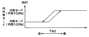
次に、FrTAOPa、FrTAODrの平均値(以下、前席用目標平均値という)に基づいて、図9の制御マップにより、内気循環モードおよび外気導入モードのいずれか一方を内外気切替モードとして決定する(ステップS124)。内気循環モードでは、内気導入口50aより車室内空気(内気)を導入し、外気導入モードでは、外気導入口50bより車室外空気(外気)を導入する。
Next, based on the average value of FrTAOPa and FrTAODr (hereinafter referred to as the front seat target average value), either the inside air circulation mode or the outside air introduction mode is determined as the inside / outside air switching mode according to the control map of FIG. (Step S124). In the inside air circulation mode, vehicle interior air (inside air) is introduced from the inside
具体的には、図9に示すように、FrTAOPa、FrTAODrの平均値(図9中のTAOに相当する)が所定温度以下となる領域(最大冷房域)では、内外気切替ドア51により内気導入口50aを全開し、外気導入口50bを全閉する内気循環モードを選択し、FrTAOPa、FrTAODrの平均値が所定温度より高くなると、内外気切替ドア51により外気導入口50bを全開し、内気導入口50aを全閉する外気導入モードを選択する。
Specifically, as shown in FIG. 9, in the area where the average value of FrTAOPa and FrTAODr (corresponding to TAO in FIG. 9) is a predetermined temperature or less (maximum cooling area), the inside / outside
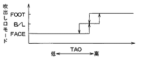
次に、図10により吹出口モードを前席側空調ゾーン1a、1bに対して個別に決定する(ステップS125)。図10は、予めROMに記憶されている吹出口モード決定の制御マップであって、本例では、FrTAODr(図10中のTAOに相当する)が上昇するにつれて、空調ゾーン1aの吹出口モードをフェイス(FACE)モード→バイレベル(B/L)モード→フット(FOOT)モードと順次自動的に切り替える。また、FrTAOPa(図10中のTAOに相当する)が上昇するにつれて、空調ゾーン1bの吹出口モードをフェイス(FACE)モード→バイレベル(B/L)モード→フット(FOOT)モードと順次自動的に切り替えるようになっている。
Next, the outlet mode is individually determined for the front seat
ここで、フェイスモードとは、フェイス吹出口だけから空調風を吹き出すモードであり、フットモードとは、フット吹出口だけから空調風を吹き出しモードである。また、バイレベルモードとは、フェイス吹出口およびフット吹出口から空調風を吹き出すモードである。 Here, the face mode is a mode in which conditioned air is blown out only from the face outlet, and the foot mode is a mode in which conditioned air is blown out only from the foot outlet. The bi-level mode is a mode in which conditioned air is blown out from the face air outlet and the foot air outlet.
たとえば、フェイスモードでは、吹出口切替ドア56a(56b)にてフェイス吹出口2a(2b)を開口し、フェイス吹出口2a(2b)のみから空調風が車室内の乗員上半身側へ吹き出す。バイレベルモードでは、吹出口切替ドア56a(56b)にてフェイス吹出口2a(2b)およびフット吹出口(図示せず)を開口し、空調風がフェイス吹出口2a(2b)およびフット吹出口から車室内の乗員上半身側および乗員下半身側へ同時に吹き出す。フットモードでは、吹出口切替ドア(図示せず)にてフット吹出口を全開し、フット吹出口から主に空調風が車室内の乗員下半身側へ吹き出す。
For example, in the face mode, the
このように、空調ゾーン毎に吹出口モードを決定すると、各吹出口切替ドアのそれぞれのサーボモータを空調ゾーン毎に制御して、空調ゾーン毎にこの決定される吹出口モードとなるように各吹出口切替ドアをそれぞれ開閉させる。 As described above, when the air outlet zone is determined for each air conditioning zone, each servo motor of each air outlet switching door is controlled for each air conditioning zone so that the air outlet mode determined for each air conditioning zone is set. Open and close the air outlet switching doors.
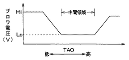
次に、上述の目標吹出温度FrTAOPa、FrTAODrの平均値に基づいて、送風機モータ52aに印加するブロワ電圧を決定する(ステップS126)。このブロワ電圧としては、送風機52の風量を制御するためのもので、FrTAOPa、FrTAODrの平均値に基づいて、予めROM内に記憶された図11の制御マップにしたがって決定されるものである。
Next, the blower voltage to be applied to the
図11の制御マップにおいて、図11中のTAOがFrTAOPa、FrTAODrの平均値に相当し、この平均値(=TAO)が中間領域内にあるときには、ブロワ電圧(すなわち送風機52の風量)が一定値となり、TAOが中間領域より大きい場合にはこのTAOが大きくなるほどブロワ電圧(すなわち送風機52の風量)が大きくなる。また、TAOが中間領域より小さい場合にはTAOが小さくなるほどブロワ電圧(すなわち送風機52の風量)が小さくなる。このようにして、ブロワ電圧が決定される。 In the control map of FIG. 11, TAO in FIG. 11 corresponds to the average value of FrTAOPa and FrTAODr, and when this average value (= TAO) is in the intermediate region, the blower voltage (that is, the air volume of the blower 52) is a constant value. When the TAO is larger than the intermediate region, the blower voltage (that is, the air volume of the blower 52) increases as the TAO increases. When TAO is smaller than the intermediate region, the blower voltage (that is, the air volume of the blower 52) decreases as TAO decreases. In this way, the blower voltage is determined.
次に、エアミックスドア55a、55bの目標開度θ1、θ2を次の数式3、4によって算出する(ステップS127)。
Next, target opening degrees θ1 and θ2 of the
θ1={(FrTAODr−TeFr)/(Tw−TeFr)}×100(%) ・・・(数式3)
θ2={(FrTAOPa−TeFr)/(Tw−TeFr)}×100(%) ・・・(数式4)
なお、数式3、4において、TeFrは蒸発器温度センサ86の蒸発器吹出温度信号、Twは冷却水温度センサ82の冷却水(温水)温度信号である。θ1=0%およびθ2=0%は、最大冷房位置であり、運転席側通路50cおよび助手席側通路50dにおいて、前席側のエバポレータ53通過後の空気(冷風)の全量がバイパス通路51a、51bを流れる。また、θ1=100%およびθ2=100%は、最大暖房位置であり、運転席側通路50cおよび助手席側通路50dにおいて、前席側のエバポレータ53通過後の空気(冷風)の全量がコアヒータ54に流入して加熱される。
θ1 = {(FrTAODr−TeFr) / (Tw−TeFr)} × 100 (%) (Formula 3)
θ2 = {(FrTAOPa−TeFr) / (Tw−TeFr)} × 100 (%) (Formula 4)
In Equations 3 and 4, TeFr is an evaporator outlet temperature signal of the
以上のように決定したブロワ電圧、目標開度θ1、θ2、内外気切替モード、吹出口モードのそれぞれを示す各制御信号をサーボモータ510a、550a、550b、560a、560bおよび送風機モータ52a等に出力して内外気切替ドア51、エアミックスドア55a、55b、吹出口切替ドア56a、56b、送風機52の各作動を制御する(ステップS128)。
Control signals indicating the blower voltage, the target opening θ1, θ2, the inside / outside air switching mode, and the outlet mode determined as described above are output to the
その後、ステップS129に移行して、一定期間経過すると、ステップS121の処理に戻り、上述の空調制御処理(ステップS121〜S129)が繰り返される。このような演算、処理の繰り返しによって前席空調ゾーン1a、1bの空調が自動的に制御されることになる。
Thereafter, the process proceeds to step S129, and when a certain period of time has elapsed, the process returns to step S121, and the above-described air conditioning control process (steps S121 to S129) is repeated. By repeating such calculation and processing, air conditioning in the front seat
(後席空調処理)
この場合、温度設定スイッチ11、12から設定温度信号RrTsetDr、RrTsetPaを読み込む(ステップS121)。さらに、外気温センサ81および日射センサ83から外気温度信号Tamdisp、日射量信号TsDr、TsPaを読み込み、IRセンサ70の熱電対部Dir1〜Dir4、Dir13〜Dir16から検出温度Tir1〜Tir4、Tir13〜Tir16を読み込む(ステップS122)。そして、IRセンサ70からの検出温度を基に、〈後部右側表面温度〉{=(Tir1+Tir2+Tir4+Tir4)/4}、〈後部左側表面温度〉{=(Tir13+Tir14+Tir15+Tir16)/4}を算出する。なお、熱電対部Dir5〜Dir12からの検出温度Tir5〜Tir12は、後部座席表面の検出温度を示しているので、目標吹出温度RrTAODr、RrTAOPaの算出には用いられていない。
(Rear seat air conditioning)
In this case, the set temperature signals RrTsetDr and RrTsetPa are read from the temperature setting switches 11 and 12 (step S121). Further, the outside air temperature signal Tamdisp and the solar radiation amount signals TsDr and TsPa are read from the outside air temperature sensor 81 and the
そして、〈後部右側表面温度〉、設定温度信号RrTsetDr、日射量信号TsDr、外気温信号Tamdispを数式5に代入して、車室内に吹き出す空気の目標吹出温度RrTAODrを算出する(ステップS123)。 Then, the <rear rear right surface temperature>, the set temperature signal RrTsetDr, the solar radiation signal TsDr, and the outside air temperature signal Tamdisp are substituted into Equation 5 to calculate the target blowing temperature RrTAODr of the air blown into the vehicle interior (step S123).
この目標吹出温度RrTAODrは、車両環境条件(空調熱負荷条件)の変動にかかわらず、後席右側空調ゾーン1cの温度を設定温度RrTsetDrに維持するために必要な目標温度である。
This target outlet temperature RrTAODr is a target temperature required to maintain the temperature of the rear seat right air-
RrTAODr=RrKset×RrDrTset
−Kir×〈後部右側表面温度〉
−KamDr×Tamdisp
−RrKs×TsDr−RrCDr・・・(数式5)
ここで、RrKsetDr(=7.0)は、後席右側用温度設定ゲイン、RrKamDr(=1.1)は、外気温ゲイン、Kir(=3.0)は、後席右側用IRゲイン、RrKs(=0.42)は、日射ゲインである。そして、RrCDrは、後席右側用補正定数である。
RrTAODr = RrKset × RrDrTset
-Kir × <Rear right surface temperature>
-KamDr x Tamdisp
−RrKs × TsDr−RrCDr (Formula 5)
Here, RrKsetDr (= 7.0) is the rear seat right side temperature setting gain, RrKamDr (= 1.1) is the outside air temperature gain, Kir (= 3.0) is the rear seat right side IR gain, and RrKs. (= 0.42) is a solar radiation gain. RrCDr is a rear seat right side correction constant.
次に、車室内の後席右側空調ゾーン1dに吹き出す空気の目標吹出温度RrTAOPaの算出について説明する。なお、目標吹出温度RrTAOPaの算出は、対象となる空調ゾーンが異なるだけで、目標吹出温度RrTAODrの算出と実質的に同様であるので、目標吹出温度RrTAOPaの算出の説明については簡素化する。
Next, calculation of the target blowing temperature RrTAOPa of the air blown out to the rear seat right
先ず、〈後部左側表面温度〉、設定温度信号RrTsetPa、日射量信号TsPa、外気温信号Tamdispを数式6に代入して、車室内に吹き出す空気の目標吹出温度RrTAOPaを算出する
この目標吹出温度RrTAOPaは、車両環境条件(空調熱負荷条件)の変動にかかわらず、後席右側空調ゾーン1dの温度を設定温度RrTsetPaに維持するために必要な目標温度である。
First, the <rear left surface temperature>, the set temperature signal RrTsetPa, the solar radiation signal TsPa, and the outside air temperature signal Tamdisp are substituted into
RrTAOPa=RrKset×RrPaTset
−Kir×〈後部右側表面温度〉
−KamPa×Tamdisp
−RrKs×TsPa−RrCPa・・・(数式6)
ここで、RrKsetPa(=7.0)は、後席左側用温度設定ゲイン、RrKamPa(=1.1)は、外気温ゲイン、Kir(=3.0)は、後席左側用IRゲイン、RrKs(=0.42)は、日射ゲインである。そして、RrCPaは、後席左側用補正定数である。
RrTAOPa = RrKset × RrPaTset
-Kir × <Rear right surface temperature>
-KamPa × Tamdisp
−RrKs × TsPa−RrCPa (Formula 6)
Here, RrKsetPa (= 7.0) is the temperature setting gain for the left rear seat, RrKamPa (= 1.1) is the outside air temperature gain, Kir (= 3.0) is the IR gain for the left rear seat, RrKs (= 0.42) is a solar radiation gain. RrCPa is a rear seat left side correction constant.
次に、内外気モードの決定処理(ステップS124)を実行せずに(これは、後席空調では外気モードが設定されていないため)、吹出口モードの決定処理(ステップS125)を実行する。この吹出口モードの決定処理では、RrTAODr、TAORrPaに基づき、図10により吹出口モードを後席側の空調ゾーン1c、1dに対して個別に決定する。
Next, without determining the inside / outside air mode determination processing (step S124) (this is because the outside air mode is not set in the rear seat air conditioning), the air outlet mode determination processing (step S125) is executed. In this process for determining the air outlet mode, the air outlet mode is individually determined for the rear seat
具体的には、空調ゾーン1cの吹出口モードとしては、図10中のTAOをRrTAODrとし、このRrTAODrが上昇するにつれて吹出口モードをフェイス(FACE)モード→バイレベル(B/L)モード→フット(FOOT)モードと順次自動的に切り替える。また、空調ゾーン1dの吹出口モードとしては、図7中のTAOをTAORrPaとし、このTAORrPaが上昇するにつれて吹出口モードをフェイスモード→バイレベルモード→フットモードと順次自動的に切り替える。
Specifically, as the air outlet mode of the air-
ここで、フェイスモードでは、吹出口切替ドア66a(66b)にてフェイス吹出口2c(2d)を開口し、フェイス吹出口2c(2d)のみから空調風が車室内の乗員上半身側へ吹き出す。バイレベルモードは、吹出口切替ドア66a(66b)にてフェイス吹出口2c(2d)およびフット吹出口(図示せず)を開口し、空調風がフェイス吹出口2c(2d)およびフット吹出口から車室内の乗員上半身側および乗員下半身側へ同時に吹き出す。フットモードは、吹出口切替ドア(図示せず)にてフット吹出口を全開し、フット吹出口から主に空調風が車室内の乗員下半身側へ吹き出す。
Here, in the face mode, the
次に、上述の目標吹出温度RrTAODr、TAORrPaの平均値(以下、後席用目標平均値という)を求め、この後席用目標平均値に基づき、図11の制御マップにしたがって、送風機モータ52aの場合と同様、送風機モータ62aに印加するブロワ電圧を決定する(ステップS126)。
Next, an average value of the above-described target blowing temperatures RrTAODr and TAORrPa (hereinafter referred to as a rear seat target average value) is obtained, and based on the rear seat target average value, according to the control map of FIG. As in the case, the blower voltage to be applied to the
次に、エアミックスドア65a、65bの目標開度θ3、θ4を次の数式7、8によって算出する。なお、TeRrは蒸発器温度センサ87の蒸発器温度信号、Twは冷却水温度センサ82の冷却水温度信号である。
Next, target opening degrees θ3 and θ4 of the
θ3={(RrTAODr−TeRr)/(Tw−TeRr)}×100(%) ・・・(数式7)
θ4={(TAORrPa−TeRr)/(Tw−TeRr)}×100(%) ・・・(数式8)
なお、数式7、8において、TeRrは蒸発器温度センサ87の蒸発器温度信号、Twは冷却水温度センサ82の冷却水(温水)温度信号である。θ3=0%およびθ4=0%は、最大冷房位置であり、後席右側通路60cおよび後席左側通路60dにおいて、後席側のエバポレータ63通過後の空気(冷風)の全量がバイパス通路61a、61bを流れる。また、θ3=100%およびθ4=100%は、最大暖房位置であり、後席右側通路60cおよび後席左側通路60dにおいて、後席側のエバポレータ63通過後の空気(冷風)の全量がコアヒータ64に流入して加熱される。
θ3 = {(RrTAODr−TeRr) / (Tw−TeRr)} × 100 (%) (Formula 7)
θ4 = {(TAORrPa−TeRr) / (Tw−TeRr)} × 100 (%) (Equation 8)
In
以上のように決定したブロワ電圧、目標開度θ3、θ4、内外気切替モード、吹出モードのそれぞれを示す各制御信号を送風機モータ62aおよびサーボモータ650a、650b、660a、660b等に出力して送風機62、エアミックスドア65a、65b、吹出口切替ドア66a、66bの作動を制御する(ステップS128)。
Control signals indicating the blower voltage, target opening degrees θ3, θ4, the inside / outside air switching mode, and the blowing mode determined as described above are output to the
その後、後席用空調ユニット6による空調ゾーン1cの空調制御内容を乗 その後、ステップS129において一定期間経過すると、ステップS121の処理に戻り、上述の空調制御処理(ステップS121、S122、S123、S125〜S129)が繰り返される。このような処理の繰り返しによって後席の空調ゾーン1c、1dの空調が自動的に制御されることになる。
Thereafter, the air conditioning control content of the
次に、本実施形態の作用効果について説明する。 Next, the effect of this embodiment is demonstrated.
本実施形態のIRセンサ70はそのセンサ視野内に後部右側座席および後部左側座席の乗員の顔部を除いて、これら乗員の太股、肩部を含むように組み付けられているので、IRセンサ70の検出温度が、髪の長さ、眼鏡の有無、マスクの有無、帽子の有無などの条件により変わることがない。これに伴い、車室内の表面温度を適切に検出することができるので、この検出された表面温度を用いて後席用空調ユニット6を制御することにより、後席左右の空調ゾーン1c、1dのそれぞれの空調を適切に行うことができる。
The
ここで、本実施形態では、1つのIRセンサ70により後席左右の空調ゾーン1c、1dの二人の乗員の表面温度を検出するように組み付けられているので、乗員一人に対して1つのIRセンサを用いる場合に比べて、低コストで車両用温度検出装置、ひいては、車両用空調装置を構成することができる。
Here, in the present embodiment, since one
(他の実施形態)
上述の各実施形態では、前席乗員、すなわち運転者および助手席乗員の表面温度を用いないで、前席空調ゾーン1a、1bの空調制御を行う例について説明したが、前席側も、後席側と同様に、前席左右列において、右側用および左側用のIRセンサ70a、70bにより右側および左側の前席乗員、すなわち運転者および助手席乗員の表面温度を検出し、この検出された前席乗員の表面温度に応じて前席右側および左側の空調ゾーン1a、1bをそれぞれ独立に空調制御してもよい。
(Other embodiments)
In each of the above-described embodiments, the example in which the air conditioning control of the front seat
また、本発明の実施にあたり、IRセンサ70は、後部右側座席および後部左側座席のうち乗員が座る頻度の低い座席の方にやや傾けて向けて配置されるようにしてもよい。
In carrying out the present invention, the
これによれば、乗員が“IRセンサ70の検出面が向けられている座席”に座る確率が少なくなるので、乗員にとっては、“IRセンサ70によって見られている”といった違和感を感じる確率が少なくなる。
According to this, since the probability that the occupant sits on the “seat on which the detection surface of the
ここで、例えば、乗員が座る頻度の低い座席とは、後席中央の座席を指す。 Here, for example, a seat with a low frequency of occupant sitting refers to a seat in the center of the rear seat.
上述の各実施形態では、IRセンサ70としてはそのセンサ視野内に乗員の太股、肩部の双方を含むように組み付けるようにした例について説明したが、これに代えて、IRセンサ70としてはそのセンサ視野内に乗員の太股、肩部のうち一方だけを含むように組み付けるようにしてもよい。
In each of the above-described embodiments, an example was described in which the
上述の各実施形態では、IRセンサ70として、入力される赤外線量の変化に対応した起電力変化を温度変化として検出するサーモパイル型検出素子を用いる例について説明したが、これに代えて、赤外線のエネルギーを直接電気信号に変換する量子型検出素子、赤外線の量の変化に対応した温度変化による自極分極を利用する焦電型検出素子、或いは、赤外線の量の変化に対応した温度変化による抵抗値変化を利用するボロメータ型検出素子を用いてもよい。
In each of the embodiments described above, an example in which a thermopile detection element that detects a change in electromotive force corresponding to a change in the amount of input infrared light as a temperature change has been described as an
1c…後席右側の空調ゾーン、1d…後席左側の空調ゾーン、
6…後席空調システム、8…エアコンECU、70…IRセンサ、
1c: rear seat right air conditioning zone, 1d rear seat left air conditioning zone,
6 ... rear seat air conditioning system, 8 ... air conditioner ECU, 70 ... IR sensor,
Claims (16)
前記非接触温度センサはそのセンサ視野内に乗員の顔部がほとんど含まないように組み付けられていることを特徴とする車両用温度検出装置。 A vehicle temperature detection device including a non-contact temperature sensor (70) in which detection elements (Dir1 to Dir16) for detecting a surface temperature of a vehicle interior in a non-contact manner are arranged in a matrix,
The vehicle temperature detecting device, wherein the non-contact temperature sensor is assembled so that the face of the occupant is hardly included in the sensor visual field.
前記非接触温度センサは、その前記車両横方向のセンサ視野角が、60°〜75°の間に設定されていることを特徴とする請求項4に記載の車両用温度検出装置。 In the passenger compartment, two seats on which the two passengers are seated are arranged side by side in the vehicle lateral direction,
The vehicle non-contact temperature sensor according to claim 4, wherein a sensor viewing angle in the vehicle lateral direction of the non-contact temperature sensor is set between 60 ° and 75 °.
前記非接触温度センサはそのセンサ視野角は、60°〜75°の間に設定されていることを特徴とする車両用温度検出装置。 A vehicle temperature detection device including a non-contact temperature sensor (70) in which detection elements (Dir1 to Dir16) for detecting a surface temperature of a vehicle interior in a non-contact manner are arranged in a matrix,
The vehicle non-contact temperature sensor has a sensor viewing angle set between 60 ° and 75 °.
前記センサ視野角は、前記二つの座席が並べられる所定方向(Y2)の角度であることを特徴とする請求項9に記載の車両用温度検出装置。 In the vehicle interior, two seats on which the two passengers are seated are arranged side by side in a predetermined direction,
The vehicle temperature detection device according to claim 9, wherein the sensor viewing angle is an angle in a predetermined direction (Y2) in which the two seats are arranged.
前記非接触温度センサは、前記二つの座席のうち乗員が座る頻度の低い座席の方に向けて配置されていることを特徴する請求項3ないし5、8ないし10のいずれか1つに記載の車両用温度検出装置。 Two seats on which the two passengers are seated are arranged side by side in the vehicle interior,
11. The non-contact temperature sensor according to claim 3, wherein the non-contact temperature sensor is arranged toward a seat of the two seats where an occupant is less frequently seated. Vehicle temperature detection device.
前記車室内の表面温度をそれぞれ非接触で検出する検出素子(Dir1〜Dir16)がマトリックス状に配列される非接触温度センサ(70)と、
前記非接触温度センサの検出温度に基づいて前記空調手段を制御する制御手段(8)と、を備える車両用空調装置であって、
前記非接触温度センサはそのセンサ視野内に乗員の顔部がほとんど含まないように組み付けられていることを特徴とする車両用空調装置。 Air-conditioning means (6) for air-conditioning the passenger compartment;
A non-contact temperature sensor (70) in which detection elements (Dir1 to Dir16) for detecting the surface temperature of the vehicle interior in a non-contact manner are arranged in a matrix;
A vehicle air conditioner comprising: control means (8) for controlling the air conditioning means based on a temperature detected by the non-contact temperature sensor;
The vehicle air conditioner is assembled so that the non-contact temperature sensor includes almost no occupant's face in the sensor field of view.
前記非接触温度センサはその前記車両横方向のセンサ視野角が、60°〜75°の間に設定されていることを特徴とする請求項15に記載の車両用空調装置。 In the passenger compartment, two seats on which the two passengers are seated are arranged side by side in the vehicle lateral direction,
16. The vehicle air conditioner according to claim 15, wherein the non-contact temperature sensor has a lateral sensor viewing angle of 60 [deg.] To 75 [deg.].
Priority Applications (1)
| Application Number | Priority Date | Filing Date | Title |
|---|---|---|---|
| JP2004120338A JP2005297903A (en) | 2004-04-15 | 2004-04-15 | Temperature detecting device for vehicle and air conditioner for vehicle |
Applications Claiming Priority (1)
| Application Number | Priority Date | Filing Date | Title |
|---|---|---|---|
| JP2004120338A JP2005297903A (en) | 2004-04-15 | 2004-04-15 | Temperature detecting device for vehicle and air conditioner for vehicle |
Publications (1)
| Publication Number | Publication Date |
|---|---|
| JP2005297903A true JP2005297903A (en) | 2005-10-27 |
Family
ID=35329957
Family Applications (1)
| Application Number | Title | Priority Date | Filing Date |
|---|---|---|---|
| JP2004120338A Pending JP2005297903A (en) | 2004-04-15 | 2004-04-15 | Temperature detecting device for vehicle and air conditioner for vehicle |
Country Status (1)
| Country | Link |
|---|---|
| JP (1) | JP2005297903A (en) |
Cited By (1)
| Publication number | Priority date | Publication date | Assignee | Title |
|---|---|---|---|---|
| CN109703322A (en) * | 2018-11-30 | 2019-05-03 | 东风汽车有限公司 | Automobile internal environment adjusting method and electronic equipment |
-
2004
- 2004-04-15 JP JP2004120338A patent/JP2005297903A/en active Pending
Cited By (2)
| Publication number | Priority date | Publication date | Assignee | Title |
|---|---|---|---|---|
| CN109703322A (en) * | 2018-11-30 | 2019-05-03 | 东风汽车有限公司 | Automobile internal environment adjusting method and electronic equipment |
| CN109703322B (en) * | 2018-11-30 | 2021-05-11 | 东风汽车有限公司 | Automobile internal environment adjusting method and electronic equipment |
Similar Documents
| Publication | Publication Date | Title |
|---|---|---|
| JP4591133B2 (en) | Air conditioner for vehicles | |
| JP4114651B2 (en) | Air conditioner for vehicles | |
| JP3861793B2 (en) | Air conditioner for vehicles | |
| JP4581906B2 (en) | Air conditioner for vehicles | |
| JP4269905B2 (en) | Air conditioner for vehicles | |
| JP4277722B2 (en) | Air conditioner for vehicles | |
| JP2005329929A (en) | Temperature detection device for vehicle and air-conditioner for vehicle | |
| JP2006240578A (en) | Seating determination device for vehicle and air conditioner for vehicle | |
| JP2005297903A (en) | Temperature detecting device for vehicle and air conditioner for vehicle | |
| JP2005138775A (en) | Temperature sensor for vehicle and air-conditioner for vehicle | |
| JP4259258B2 (en) | Air conditioner for vehicles | |
| JP2005306095A (en) | Air-conditioning control device for vehicle | |
| JP2005297902A (en) | Air conditioner for vehicle | |
| JP2004330961A (en) | Air conditioner for vehicle | |
| JP4120613B2 (en) | VEHICLE TEMPERATURE DETECTING DEVICE AND VEHICLE AIR CONDITIONER | |
| JP2005140571A (en) | Noncontact temperature sensor for vehicle, and air conditioner for vehicle | |
| JP4311125B2 (en) | Air conditioner for vehicles | |
| JP2005145133A (en) | Air conditioner for vehicle | |
| JP4525375B2 (en) | Air conditioner for vehicles | |
| JP2005147556A (en) | Temperature detection device for vehicle and air conditioner for vehicle | |
| JP4196783B2 (en) | Air conditioner for vehicles | |
| JP4292939B2 (en) | Air conditioner for vehicles | |
| JP2006248352A (en) | Temperature detecting device for vehicle and air conditioner for vehicle | |
| JP4207708B2 (en) | Air conditioner for vehicles | |
| JP4196800B2 (en) | Air conditioner for vehicles |
Legal Events
| Date | Code | Title | Description |
|---|---|---|---|
| A621 | Written request for application examination |
Free format text: JAPANESE INTERMEDIATE CODE: A621 Effective date: 20060623 |
|
| A977 | Report on retrieval |
Free format text: JAPANESE INTERMEDIATE CODE: A971007 Effective date: 20071115 |
|
| A131 | Notification of reasons for refusal |
Free format text: JAPANESE INTERMEDIATE CODE: A131 Effective date: 20071120 |
|
| A521 | Written amendment |
Free format text: JAPANESE INTERMEDIATE CODE: A523 Effective date: 20080116 |
|
| A02 | Decision of refusal |
Free format text: JAPANESE INTERMEDIATE CODE: A02 Effective date: 20080401 |