JP2005297902A - Air conditioner for vehicles - Google Patents
Air conditioner for vehicles Download PDFInfo
- Publication number
- JP2005297902A JP2005297902A JP2004120337A JP2004120337A JP2005297902A JP 2005297902 A JP2005297902 A JP 2005297902A JP 2004120337 A JP2004120337 A JP 2004120337A JP 2004120337 A JP2004120337 A JP 2004120337A JP 2005297902 A JP2005297902 A JP 2005297902A
- Authority
- JP
- Japan
- Prior art keywords
- air
- temperature
- seat
- occupant
- temperature sensor
- Prior art date
- Legal status (The legal status is an assumption and is not a legal conclusion. Google has not performed a legal analysis and makes no representation as to the accuracy of the status listed.)
- Withdrawn
Links
Images
Landscapes
- Air-Conditioning For Vehicles (AREA)
Abstract
【課題】 車両用空調装置が備える非接触温度センサが、乗員の座高や姿勢の変化、さらにはシートの位置や姿勢に拘らず安定した乗員の表面温度の検出ができるようにする。
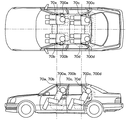
【解決手段】 所定の形状および大きさの被検温範囲700a〜700dを備える非接触温度センサ70a〜70dを、車室内天井において、前席左右および後席左右の各着座位置の中心より近傍のサイドウインドウ寄りでかつ、各着座位置の上方に配置して、各座席に着座する乗員のサイドウインドウ側の肩の上部の表面温度を非接触で検出する。これにより、乗員の座高や乗員の着座姿勢が変化しても、肩上部は、肩を上方から見ている各非接触温度センサの被検温範囲から外れることはなく、安定して乗員温度を検出することができる。
【選択図】 図5
PROBLEM TO BE SOLVED: To provide a non-contact temperature sensor provided in an air conditioner for a vehicle, which can detect a stable passenger surface temperature regardless of a change in the seat height and posture of the occupant, and regardless of the position and posture of the seat.
SOLUTION: Non-contact temperature sensors 70a to 70d having test temperature ranges 700a to 700d having a predetermined shape and size are arranged on the side of the vehicle interior ceiling in the vicinity of the front seat left and right and rear seat left and right seating center. The surface temperature of the upper part of the shoulder on the side window side of the occupant seated in each seat is detected in a non-contact manner by being placed near the window and above each seating position. As a result, even if the occupant's sitting height or occupant's sitting posture changes, the upper shoulder does not deviate from the detected temperature range of each non-contact temperature sensor looking at the shoulder from above, and the occupant temperature is detected stably. can do.
[Selection] Figure 5
Description
本発明は、乗員の表面温度を非接触で検出する非接触温度センサを備えた車両用空調装置に関する。 The present invention relates to a vehicle air conditioner including a non-contact temperature sensor that detects the surface temperature of an occupant in a non-contact manner.
従来、前席シート後部に非接触温度センサとしての後席用IR(赤外線)センサを設け、この後席用IRセンサにより後席乗員の表面温度を測定するものがあった(例えば、特許文献1参照)。
しかし、上記従来技術では、後席用IRセンサが前席のシートカバーで隠されて測定ができなくなるおそれがあるばかりでなく、前席のシート位置またはリクライニングにより後席用IRセンサの視野方向が変化してしまい、後席乗員の必要な部位の温度を検出することができなるという問題があった。 However, in the above-described prior art, the rear-seat IR sensor may be hidden by the front-seat seat cover and cannot be measured, and the viewing direction of the rear-seat IR sensor may vary depending on the seat position or reclining of the front seat. There has been a problem that the temperature of a necessary part of the rear seat occupant cannot be detected.
さらに、空調制御の指標となる乗員の温度として、個人差が大きい顔の皮膚温度よりも、肩部のような衣服に覆われている部位の温度の方が望ましいが、上記従来技術では、後席用IRセンサが後席乗員の前方から見ているので、例えば乗員の体格、特に座高が異なる場合や乗員の着座姿勢が変化すると、乗員の肩の位置も変化してしまい、正しい温度を検出することができなくなるという問題があった。 Further, as the temperature of the occupant serving as an index for air conditioning control, the temperature of the part covered with clothes such as the shoulder is more preferable than the skin temperature of the face, which has a large individual difference. Because the IR sensor for the seat is seen from the front of the rear seat occupant, for example, when the occupant's physique, especially when the seat height is different, or when the occupant's sitting posture changes, the position of the occupant's shoulder also changes, and the correct temperature is detected. There was a problem that it was impossible to do.
本発明は、上記点に鑑み、車両用空調装置が備える非接触温度センサが、乗員の座高や姿勢の変化、さらにはシートの位置や姿勢に拘らず安定した乗員の表面温度の検出ができるようにすること目的とする。 In the present invention, in view of the above points, the non-contact temperature sensor provided in the vehicle air conditioner can detect a stable passenger surface temperature regardless of changes in the seat height and posture of the passenger, and the position and posture of the seat. The purpose is to make.
上記目的を達成するため、請求項1に記載の発明では、車室(1)内において乗員の着座位置の上方であって前記着座位置の中心より前記着座位置近傍のサイドウインドウ寄りに配置されるとともに、所定の被検温範囲(700a、700b、700c、700d)が少なくとも前記乗員の前記サイドウインドウ側の肩の上部を含むよう設けられ、前記被検温範囲の温度を非接触で検出する非接触温度センサ(70a、70b、70c、70d)と、
前記非接触温度センサにより検出された温度に基づいて前記車室内の空調状態を調整する空調手段(5、6、8)と、
を備えることを特徴とする。
In order to achieve the above object, according to the first aspect of the present invention, the vehicle is disposed above the seating position of the occupant in the passenger compartment (1) and closer to the side window near the seating position than the center of the seating position. In addition, a predetermined test temperature range (700a, 700b, 700c, 700d) is provided so as to include at least an upper portion of the shoulder on the side window side of the occupant, and detects the temperature of the test temperature range in a non-contact manner. Sensors (70a, 70b, 70c, 70d);
Air-conditioning means (5, 6, 8) for adjusting the air-conditioning state of the vehicle interior based on the temperature detected by the non-contact temperature sensor;
It is characterized by providing.
この発明によれば、非接触温度センサを乗員の着座位置の上方で、かつ、この着座位置の中心、すなわち着座している乗員の身体中心よりサイドウインドウ寄りに配置する。すなわち、右側座席に対してはこの右側座席に着座する乗員の、着座位置近傍の右サイドウインドウ寄り、すなわち右肩寄りの上方に非接触センサを配置する。一方、左側座席に対してはこの左側座席に着座する乗員の、着座位置近傍の左サイドウインドウ寄り、すなわち左肩寄りの上方に非接触センサを配置する。そして、このように配置された非接触温度センサの被検温範囲を着座乗員の肩の上部を含むように設定する。ここで、肩の上部とは、肩峰部など肩の上面を含み、人体の前部の鎖骨から後部の肩甲骨にわたる範囲をいう。 According to the present invention, the non-contact temperature sensor is disposed above the seating position of the occupant and closer to the side window than the center of the seating position, that is, the body center of the seated occupant. That is, with respect to the right seat, a non-contact sensor is disposed above the right side window in the vicinity of the seating position, that is, near the right shoulder of the passenger seated in the right seat. On the other hand, with respect to the left seat, a non-contact sensor is disposed above the left side window near the seating position of the passenger seated in the left seat, that is, above the left shoulder. And the to-be-tested temperature range of the non-contact temperature sensor arrange | positioned in this way is set so that the upper part of the shoulder of a seated passenger | crew may be included. Here, the upper part of the shoulder means the range from the clavicle at the front of the human body to the scapula at the rear, including the upper surface of the shoulder such as the acromion.
したがって、非接触温度センサが乗員の近傍のサイドウインドウ側の肩の上部を、乗員の上方から見るので、乗員の座高や姿勢の変化、およびシート位置・姿勢によらず、安定した乗員の温度検出が可能になるとともに、乗員近傍のサイドウインドウ側の肩上部の温度を検出するので、サイドウインドウからの側方日射による乗員温度上昇や、あるいはサイドウインドウからの冷輻射による乗員温度低下などの影響を正しく反映した温度を検出することができ、これらの影響を考慮した空調を行って快適性を向上させることができる。 Therefore, since the non-contact temperature sensor looks at the upper part of the shoulder on the side window near the occupant from above the occupant, stable occupant temperature detection is possible regardless of changes in the occupant's sitting height, posture, and seat position / posture. Since the temperature of the upper shoulders on the side window side near the occupant is detected, there is an effect such as an increase in occupant temperature due to side solar radiation from the side window or a decrease in occupant temperature due to cold radiation from the side window. The correctly reflected temperature can be detected, and comfort can be improved by performing air conditioning in consideration of these effects.
非接触温度センサは、請求項2に記載のように、着座位置より車室前方寄りの着座位置の上方に設けることができる。これにより、乗員の肩部の人体前部の温度を検出することができ、乗員の前方への姿勢変化に対しても、その影響を小さくすることができる。
As described in
また、非接触温度センサは、請求項3に記載のように、着座位置より車室後方寄りの着座位置の上方に設けることができる。これにより、非接触温度センサは、乗員のやや後ろ側から乗員の肩部の温度を検出するように、すなわち乗員の視界の範囲外に配置されるので、乗員の、非接触温度センサに見られているという違和感をなくすことができる。 Further, as described in claim 3, the non-contact temperature sensor can be provided above the seating position closer to the rear of the passenger compartment than the seating position. Thereby, the non-contact temperature sensor is arranged so as to detect the temperature of the shoulder of the occupant from the slightly rear side of the occupant, that is, outside the range of the sight of the occupant. You can eliminate the sense of discomfort.
あるいは、非接触温度センサは、請求項4に記載のように、被検温範囲が乗員の肩の上部と車室内の車体内装部位とを同一範囲内に含むよう設けることができる。これにより、乗員の肩部の温度に加えて車体内装からの輻射の影響が反映された温度を検出することができ、これを空調制御のパラメータとして用いれば、より空調快適性を向上させることができる。 Alternatively, as described in claim 4, the non-contact temperature sensor can be provided so that the temperature range to be detected includes the upper part of the shoulder of the occupant and the vehicle interior part in the vehicle interior. Thereby, in addition to the temperature of the passenger's shoulder, it is possible to detect a temperature that reflects the influence of radiation from the vehicle interior, and if this is used as a parameter for air conditioning control, air conditioning comfort can be further improved. it can.
また、非接触温度センサは、請求項5に記載のように、被検温範囲が乗員の肩の上部とサイドウインドウとを同一範囲内に含むよう設けることができる。これにより、乗員の肩部の温度に加えて近傍のサイドウインドウからの輻射の影響が反映された温度を検出することができ、これを空調制御のパラメータとして用いれば、より空調快適性を向上させることができる。 Further, as described in claim 5, the non-contact temperature sensor can be provided so that the temperature range to be detected includes the upper part of the shoulder of the occupant and the side window within the same range. Thereby, in addition to the temperature of the passenger's shoulder, the temperature reflecting the influence of radiation from the nearby side window can be detected, and if this is used as a parameter for air conditioning control, air conditioning comfort is further improved. be able to.
さらに、請求項6に記載のように、非接触温度センサは、被検温範囲の乗員の顔側の端において、肩の上部が被検温範囲とされるよう設ける、すなわち、被検温範囲には顔部が含まれないようにすることができる。顔部が非接触温度センサの被検温範囲に入ってしまうと、頭髪の多寡や長さなど個人差が大きいため、検出温度に差が生じやすい。したがって、被検温範囲から顔部を除くことにより、乗員の個人差に影響されず、安定した乗員温度の検出が可能になる。
Further, as described in
なお、非接触温度センサは、請求項7に記載のように、車室内の後部左座席および後部右座席にそれぞれ対応するように、左側サイドウインドウ寄りに配置されている後部左座席用非接触温度センサと右側サイドウインドウ寄りに配置されている後部右座席用非接触温度センサとをそれぞれ別個に設置することにより、後部左側乗員の肩温度と後部右側乗員の肩温度とを独立に検出することができ、それぞれの検出温度に基づいて車室内の空調状態を調整して、後部の左右座席のそれぞれに快適な空調空間を創出することができる。
The non-contact temperature sensor, as described in
空調手段は、請求項8に記載のように、非接触温度センサにより検出された乗員の肩上部の温度に基づき目標吹出温度を算出するとともに、この目標吹出温度に基づき被検温範囲の空調状態を調整するようにすれば、乗員の快適性を向上させることができる。 The air conditioning means calculates the target blowing temperature based on the temperature of the upper shoulder of the occupant detected by the non-contact temperature sensor, and determines the air conditioning state of the temperature range to be detected based on the target blowing temperature. If adjusted, passenger comfort can be improved.
なお、上記各手段の括弧内の符号は、後述する実施形態に記載の具体的手段との対応関係を示すものである。 In addition, the code | symbol in the bracket | parenthesis of each said means shows the correspondence with the specific means as described in embodiment mentioned later.
(第1実施形態)
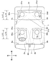
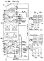
以下、本発明の第1実施形態について図面を参照して説明する。図1は本実施形態による車両用空調装置の室内空調ユニット部の吹出口配置状態を示す平面概要図、図2は室内空調ユニット部および制御ブロックを含む全体構成図である。
(First embodiment)
Hereinafter, a first embodiment of the present invention will be described with reference to the drawings. FIG. 1 is a schematic plan view showing an air outlet arrangement state of an indoor air conditioning unit of the vehicle air conditioner according to this embodiment, and FIG. 2 is an overall configuration diagram including the indoor air conditioning unit and a control block.
本第1実施形態は、車室内1の前後左右の計4つの空調ゾーン1a、1b、1c、1dをそれぞれ独立して空調制御する。図1、図2は右ハンドル車の場合を示しており、上記空調ゾーン1a〜1dをより具体的に説明すると、空調ゾーン1aは、前席空調ゾーンのうち右サイドウインドウ側、すなわち、運転席側に位置する。空調ゾーン1bは、前席空調ゾーンのうち左サイドウインドウ側、すなわち、助手席側に位置する。
In the first embodiment, a total of four air-
そして、空調ゾーン1cは、後席空調ゾーンのうち右側窓(サイドウインドウ)寄りに位置し、空調ゾーン1dは、後席空調ゾーンのうち左側窓(サイドウインドウ)寄りに位置する。なお、図1中、後部座席の乗員の尻部が当たる座面をシートクッション部30、乗員の背があたる面をシートバック部31として示し、特に後席右側(左側)乗員のシートクッション部30c(30d)、シートバック部31c(30d)として図示している。また、図1中の前後左右の各矢印は、車両搭載時における前後左右の方向を示す。
The
車両用空調装置の室内空調ユニット部は空調手段としての前席用空調ユニット5と後席用空調ユニット6とから構成されている。前席用空調ユニット5は、前席左右の空調ゾーン1a、1bのそれぞれの空調状態(例えば、空気温度)を独立して調整するためのものであり、後席用空調ユニット6は、後席左右の空調ゾーン1c、1dのそれぞれの空調状態を独立して調整するためのものである。
The indoor air conditioning unit of the vehicle air conditioner is composed of a front seat air conditioning unit 5 and a rear seat
前席用空調ユニット5は、車室内1の最前部の計器盤7の内側に配置されており、後席用空調ユニット6は、車室内1の最後方に配置されている。前席用空調ユニット5は、車室内1の前席側に空気を送風するためのダクト50を備えている。このダクト50の最上流部には、車室内1から内気を導入するための内気導入口50aおよび車室外から外気を導入するための外気導入口50bが設けられている。
The front seat air conditioning unit 5 is disposed inside the
さらに、ダクト50には、外気導入口50bおよび内気導入口50aを選択的に開閉する内外気切替ドア51が設けられており、この内外気切替ドア51には、駆動手段としてのサーボモータ510aが連結されている。
Further, the
また、ダクト50内のうち外気導入口50bおよび内気導入口50aの空気下流側には、車室内1に向けて吹き出される空気流を発生させる遠心式送風機52が設けられている。遠心式送風機52は、遠心式羽根車およびこの羽根車を回転させるブロワモータ52aにより構成されている。なお、図2において、この羽根車は図の簡略化のため軸流式羽根車を示しているが、実際は遠心式の羽根車が使用されている。
A
さらに、ダクト50内にて遠心式送風機52の空気下流側には、空気を冷却する空気冷却手段としてのエバポレータ53が設けられており、さらに、このエバポレータ53の空気下流側には、空気加熱手段としてのヒータコア54が設けられている。
Further, an
そして、ダクト50内のうちエバポレータ53の空気下流側には仕切り板57が設けられており、この仕切り板57により、ダクト50内の空気通路を車両左右両側の2つの通路、すなわち、運転席側通路50cと助手席側通路50dとに仕切っている。
A
運転席側通路50cのうちヒータコア54の側方には、バイパス通路51aが形成されており、バイパス通路51aは、ヒータコア54に対して、エバポレータ53により冷却された冷風をバイパスさせる。
A
同様に、助手席側通路50dのうちヒータコア54の側方には、バイパス通路51bが形成されており、バイパス通路51bは、ヒータコア54に対して、エバポレータ53により冷却された冷風をバイパスさせる。
Similarly, a
運転席側通路50cおよび助手席側通路50dにおいてヒータコア54の空気上流側に、それぞれ、エアミックスドア55a、55bが独立に操作可能に設けられている。運転席側のエアミックスドア55aは、その開度により、運転席側通路50cを流通する冷風のうちヒータコア54を通る量(温風量)とバイパス通路51aを通る量(冷風量)との比を調整して、前席運転席側の空調ゾーン1aへの吹出空気温度を調整する。
In the driver
同様に、助手席側のエアミックスドア55bは、その開度により、助手席側通路50dを流通する冷風のうちヒータコア54を通る量(温風量)とバイパス通路51bを通る量(冷風量)との比を調整して、前席助手席側の空調ゾーン1bへの吹出空気温度を調整する。
Similarly, the
なお、前席左右のエアミックスドア55a、55bには、駆動手段としてのサーボモータ550a、550bがそれぞれ連結されており、エアミックスドア55a、55bの開度は、サーボモータ550a、550bによって、それぞれ独立に調整される。
In addition,
エバポレータ53は、図示しないコンプレッサ、凝縮器、受液器、減圧器とともに、周知の冷凍サイクルを構成している低圧側の冷却用熱交換器である。このエバポレータ53は、ダクト50内を流れる空気から低圧側冷媒が蒸発潜熱を吸熱して蒸発することにより、ダクト50内の空気を冷却する。なお、冷凍サイクルのコンプレッサは、車両エンジンに電磁クラッチ(図示しない)を介して連結され、電磁クラッチを断続制御することによって駆動停止制御される。
The
ヒータコア54は、車両エンジンからの温水(エンジン冷却水)を熱源とする加熱用熱交換器であり、このヒータコア54は蒸発器53通過後の空気を加熱する。
The
運転席側通路50cおよび助手席側通路50dのうちヒータコア54の空気下流側(最下流部)には、運転席側フェイス吹出口2aおよび助手席側フェイス吹出口2bが設けられている。
Of the driver
運転席側フェイス吹出口2aは、運転席側通路50cから運転席に着座する運転席乗員の上半身に向けて空気を吹き出す。また、助手席側フェイス吹出口2bは、助手席側通路50dから助手席に着座する助手席乗員の上半身に向けて空気を吹き出す。
The driver-seat-
さらに、運転席側通路50cおよび助手席側通路50dのうち運転席側フェイス吹出口2aおよび助手席側フェイス吹出口2bの各空気上流部には、それぞれ、運転席側フェイス吹出口2aを開閉する吹出口切替ドア56aおよび助手席側フェイス吹出口2bを開閉する吹出口切替ドア56bが設けられている。これら吹出口切替ドア56aおよび56bは、それぞれ駆動手段としての運転席側のサーボモータ560a、および助手席側のサーボモータ560bによって、開閉駆動される。
Furthermore, the driver's seat
なお、運転席側フェイス吹出口2aと助手席側フェイス吹出口2bは、具体的には図1に示すようにそれぞれ、計器盤7の左右方向の中央部寄り部位に位置するセンターフェイス吹出口と計器盤7の左右方向の両端部付近に位置するサイドフェイス吹出口とに分けて配置される。
The driver's seat-
また、図1、図2には図示していないが、運転席側通路50cの最下流部には、上記運転席側フェイス吹出口2aの他に、運転席側フット吹出口および運転席側デフロスタ吹出口が設けられている。運転席側フット吹出口は運転席側通路50cから運転者の下半身に空気を吹き出す。運転席側デフロスタ吹出口は運転席側通路50cからフロントガラスの内表面のうち運転席側領域に空気を吹き出す。
Although not shown in FIGS. 1 and 2, in addition to the driver-seat-
同様に、助手席側通路50dの最下流部には、上記助手席側フェイス吹出口2bの他に、助手席側フット吹出口および助手席側デフロスタ吹出口が設けられている。助手席側フット吹出口は助手席側通路50dから助手席乗員の下半身に空気を吹き出す。助手席側デフロスタ吹出口は助手席側通路50dからフロントガラスの内表面のうち助手席側領域に空気を吹き出す。
Similarly, a passenger seat side foot outlet and a passenger seat side defroster outlet are provided in the most downstream part of the passenger
そして、運転席側通路50cにおいて運転席側フット吹出口および運転席側デフロスタ吹出口の空気上流部には、それぞれの吹出口を開閉する吹出口切替ドア(図示せず)が設けられている。そして、これら運転席側のフェイス、フットおよびデフロスタの各吹出口切替ドアは、上述した運転席側のサーボモータ560aにより連動して開閉駆動される。
In the driver
また、助手席側通路50dにおいて助手席側フット吹出口および助手席側デフロスタ吹出口の空気上流部には、それぞれの吹出口を開閉する吹出口切替ドア(図示せず)が設けられている。そして、これら助手席側のフェイス、フットおよびデフロスタの各吹出口切替ドアは、上述した助手席側のサーボモータ560bにより連動して開閉駆動される。
Further, in the passenger
後席用空調ユニット6は、車室内1に送風するためのダクト60を備えている。このダクト60内の最上流部には、車室内1から内気導入口60aを通して内気のみを導入する内気導入ダクト60bが接続されている。
The rear seat
内気導入ダクト60bの空気下流側には、車室内1に向けて吹き出される空気流を発生させる遠心式送風機62が設けられている。遠心式送風機62は、遠心式羽根車およびこの羽根車を回転させるブロワモータ62aにより構成されている。なお、この羽根車も図2において、上記と同様、図の簡略化のため軸流式羽根車を示しているが、実際は遠心式の羽根車が使用されている。
A
さらに、ダクト60内において遠心式送風機62の空気下流側には、空気を冷却する空気冷却手段としてのエバポレータ63が設けられており、このエバポレータ63の空気下流側には、空気を加熱する空気加熱手段としてのヒータコア64が設けられている。
Further, an
そして、ダクト60内のうちエバポレータ63の下流部分には仕切り板67が設けられており、この仕切り板67により、ダクト60内の空気通路を車両左右両側の2つの通路、すなわち、後席右側通路(後席運転席側通路)60cと後席左側通路(後席助手席側通路)60dとに仕切っている。
A
後席右側通路60cのうちヒータコア64の側方には、バイパス通路61aが形成されており、バイパス通路61aは、ヒータコア64に対してエバポレータ63により冷却された冷風をバイパスさせる。
A
また、後席左側通路60dのうちヒータコア64の側方には、バイパス通路61bが形成されており、バイパス通路61bは、ヒータコア64に対してエバポレータ63により冷却された冷風をバイパスさせる。
Further, a
後席右側通路60cおよび後席左側通路60dにおいてヒータコア64の空気上流側には、それぞれエアミックスドア65a、65bが独立に操作可能に設けられている。これら後席右側および後席左側のエアミックスドア65a、65bには、駆動手段としてのサーボモータ650a、650bがそれぞれ連結されており、後席右側および後席左側のエアミックスドア65a、65bの開度は、サーボモータ650a、650bによって、それぞれ独立に調整される。
In the rear seat
そして、後席右側および後部左側のエアミックスドア65a、65bは、それぞれ、その開度により、後席右側通路60cおよび後席左側通路60dを流通する冷風のうちヒータコア64を通る量(温風量)とバイパス通路61aおよび61bとを通る量(冷風量)との比を調整して、後席右側および後席左側の空調ゾーン1c、1dへの吹出空気温度を調整する。
The
エバポレータ63は、上述した周知の冷凍サイクルにおいて前席側のエバポレータ53に対して並列的に配管結合される冷却用熱交換器である。また、ヒータコア64は、車両エンジンからの温水(エンジン冷却水)を熱源とする加熱用熱交換器であり、ヒータコア64は、温水回路において前席側のヒータコア54に対し並列的に接続され、エバポレータ63通過後の空気を加熱する。
The
ダクト60内の後席右側通路60cのうちヒータコア64の空気下流側(最下流部)には、後席右側フェイス吹出口2cが設けられている。後席右側フェイス吹出口2cは、後席右側通路60cから後席の右側(すなわち、後席運転席側)に着座する乗員(以下、後席右側乗員という)の上半身に向けて空気を吹き出す。
A rear seat
また、ダクト60内の後席左側通路60dのうちヒータコア64の空気下流側(最下流部)には、後席左側フェイス吹出口2dが設けられている。後席左側フェイス吹出口2dは、後席左側通路60dから後席の左側(すなわち、後席助手席側)に着座する乗員(以下、後席左側乗員という)の上半身に向けて空気を吹き出す。
In addition, a rear seat left
ここで、後席左右の各フェイス吹出口2c、2dの空気上流部には、それぞれ吹出口切替ドア66a、66bが設けられ、後席左右の各フェイス吹出口2c、2dを開閉するようになっている。この後席左右の吹出口切替ドア66a、66bは、駆動手段としてのサーボモータ660a、660bによって開閉駆動される。
Here, air
そして、図1、図2には図示しないが、後席右側通路60cの最下流部には、後席右側フェイス吹出口2cの他に後席右側フット吹出口が設けられている。この後席右側フット吹出口は、後席右側通路60cから空気を後席右側乗員の下半身に向けて吹き出す。
Although not shown in FIGS. 1 and 2, a rear seat right foot outlet is provided in the most downstream portion of the rear seat
同様に、後席左側通路60dの最下流部には、後席左側フェイス吹出口2dの他に後席左側フット吹出口が設けられている。この後席左側フット吹出口は、後席左側通路60dから空気を後席左側乗員の下半身に向けて吹き出す。
Similarly, a rear seat left foot outlet is provided in the most downstream portion of the rear seat left
この後席左右の各フット吹出口の空気上流部には、それぞれ吹出口切替ドア(図示せず)が設けられており、この後席左右の各吹出口切替ドアは、上記サーボモータ660c、660dによってそれぞれ開閉駆動される。 Air outlet switching doors (not shown) are provided in the air upstream portions of the left and right foot outlets of the rear seat, and the servo motors 660c and 660d are provided at the outlet right and left rear door switching doors. Are driven to open and close respectively.
制御手段(空調制御装置)としてのエアコンECU8の入力側には、外気温度センサ81、冷却水温度センサ82、日射センサ83、内気温度センサ84、85および蒸発器温度センサ86、87が接続されている。
An outside
外気温度センサ81は、車室外温度を検出しその検出温度に応じた外気温度信号TamをエアコンECU8に出力する。冷却水温度センサ82は、エンジンの冷却水(すなわち温水)の温度を検出しその検出温度に応じた冷却水温度信号TwをエアコンECU8に出力する。
The outside
日射センサ83は、フロントウインドウの内側にて車両左右方向の略中央部分に配置された周知の2素子(2D)タイプの日射センサであり、車室内の運転席側空調ゾーン1aに入射される日射量と助手席側空調ゾーン1bに入射される日射量とを検出し、それら検出した各日射量に応じた日射量信号TsDrおよびTsPaをエアコンECU8に出力する。
The
内気温度センサ84は、車室内の空調ゾーン1a、1b(前席側空調領域)の空気温度を検出しその検出温度に応じた内気温度信号TrFrをエアコンECU8に出力する。内気温度センサ85は、車室内の空調ゾーン1c、1d(後席側空調領域)の空気温度を検出しその検出温度に応じた内気温度信号TrRrをエアコンECU8に出力する。
The inside
蒸発器温度センサ86は、エバポレータ53の吹出空気温度を検出しその検出温度に応じた蒸発器吹出温度信号TeFrをエアコンECU8に出力するもので、蒸発器温度センサ87は、エバポレータ63の吹出空気温度を検出しその検出温度に応じた蒸発器吹出温度信号TeRrをエアコンECU8に出力する。
The
また、エアコンECU8には、空調ゾーン1a、1b、1c、1dのそれぞれの希望温度TsetFrDr、TsetFrPa、TsetRrDr、TsetRrPaが乗員により設定される温度設定スイッチ9、10、11、12、および、前席右側の空調ゾーン1a、前席左側の空調ゾーン1b、後席右側の空調ゾーン1cおよび後席左側の空調ゾーン1dの各ゾーンの表面温度を検出するための各非接触温度センサ70a、70b、70c、および70dが接続されている。なお、温度設定スイッチ9、10、11、12のそれぞれ近傍には、希望温度等の設定内容を表示する希望温度表示手段としてのディスプレイ9a、10a、11a、12aが備えられている。
Further, the
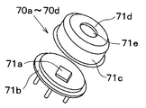
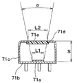
非接触温度センサ70a〜70dは、図3、4に示すように、いずれも同じ構造を備えている。すなわち、非接触温度センサ70a〜70dは、赤外線を検知する四角形の検知部(検出素子)71aが基盤71b上に設置され、検知部71aはカップ状の金属製ケース71cによって覆われている。ケース71cの底部には被検温範囲に応じた形状の窓71dがあけられ、シリコン製のカバー71eが窓71dにはめ込まれている。そして、検知部71aと窓71dとの間隔Sを適宜設定することにより、温度検出可能な角度範囲(視野角)αを調整している。したがって、非接触温度センサ70a〜70dの被検温範囲(視野範囲)は、窓71dの形状と間隔Sとにより、所望の形状とすることができる。
Each of the
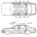
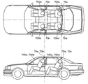
図5は、非接触温度センサ70a〜70dの設置位置を示すもので、車室1内の天井の、各空調ゾーンの座席の着座位置中心(乗員の身体中心)よりそれぞれサイドウインドウ寄りの位置であって、それぞれ各乗員の着座位置におけるシートクッション部30a、30b、30c、30dの前端部から、それぞれのシートバック部31a、31b、31c、31dの後端部までの領域Lf0、Lr0(図1参照)の上方の車室内天井部位置に配置することにより、非接触温度センサ70a〜70dは各乗員の上方から見ることができる。あるいは、より好ましくは非接触温度センサ70a〜70dをシートクッション部30a、30b、30c、30dの前端部と後端部との間の車両前後方向の領域Lf1、Lr1の上方に配置して、各乗員をより上方から見ることができる。
FIG. 5 shows the installation positions of the
そして、各非接触温度センサ70a〜70dの視野範囲(被検温範囲)700a〜700dを、各乗員のサイドウインドウ寄りの肩の上部に向くようケース71eおよびカバー71eが配置されている。
A
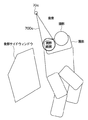
図6は、一例として、後部右側座席である空調ゾーン1cにおける非接触温度センサ70cの被検温範囲である視野範囲を示す図である。すなわち、非接触温度センサ70cは、乗員近傍のサイドウインドウである後部右側のリアウインドウ寄りの右肩の上部を主な被検温範囲(視野範囲)としている。
FIG. 6 is a diagram illustrating, as an example, a visual field range that is a test temperature range of the
このように、各非接触温度センサ70a〜70dは、それぞれ乗員のサイドウインドウ寄りの肩上部を、車室内天井より鉛直方向下方へ見ることができるので、乗員の座高や姿勢の変化により肩の位置が天地方向に変化しても、肩は被検温領域から外れる可能性が少なく、安定して乗員の肩上部の温度を検出することができる。
Thus, each
エアコンECU8は、アナログ/デジタル変換器、マイクロコンピュータ等を有して構成される周知のものであり、各非接触温度センサ70a、70b、70c、70d、日射センサ83、各温度センサ81、82、84、85、86、87および温度設定スイッチ9、10、11、12からそれぞれ出力される出力信号は、アナログ/デジタル変換器によりアナログ/デジタル変換されてマイクロコンピュータにそれぞれ入力されるように構成されている。
The
マイクロコンピュータは、ROM、RAMなどのメモリ、およびCPU(中央演算装置)等から構成される周知のもので、イグニッションスイッチがオンされたときに、図示しないバッテリから電力供給される。 The microcomputer is a well-known computer composed of a memory such as a ROM and a RAM, a CPU (Central Processing Unit), and the like, and is supplied with power from a battery (not shown) when an ignition switch is turned on.
次に、上記構成において本第1実施形態の作動を図7〜図11に基づいて説明する。 Next, the operation of the first embodiment in the above configuration will be described with reference to FIGS.
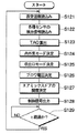
エアコンECU8は、電源が投入されると、メモリに記憶された制御プログラム(コンピュータプログラム)がスタートして、図7に示すフローチャートにしたがって空調制御処理を実行する。なお、以下では、前席空調処理および後席空調処理を分けて図7を参照して説明する。図7は各空調処理の内容を示している。
When the power is turned on, the
(前席空調処理)
まず、温度設定スイッチ9、10から設定温度信号TsetFrDr、TsetFrPaを読み込む(ステップS121)。さらに、外気温度センサ81及び日射センサ83から外気温度信号Tam、日射量信号TsDr、TsPaを、内気温度センサ84から内気温度TrFrを読み込むとともに、非接触温度センサ70a、70bから前席右側温度TirFrDr、前席左側温度TirFrPaを読み込む(ステップS122)。
(Front seat air conditioning)
First, set temperature signals TsetFrDr and TsetFrPa are read from the temperature setting switches 9 and 10 (step S121). Further, the outside air temperature sensor Tam and the
そして、設定温度信号TsetFrDr、前席右側温度TirFrDr、外気温信号Tam、日射量信号TsDrを数式1に代入して、車室内に吹き出す空気の目標吹出温度TAOFrDrを算出する(ステップS123)。この目標吹出温度TAOFrDrは、車両環境条件(空調熱負荷条件)の変動にかかわらず、前席右側(運転席)空調ゾーン1aの温度を設定温度TsetFrDrに維持するために必要な目標温度である。
Then, the set temperature signal TsetFrDr, the front seat right side temperature TirFrDr, the outside air temperature signal Tam, and the solar radiation amount signal TsDr are substituted into Equation 1 to calculate the target blowing temperature TAOFrDr of the air blown into the vehicle interior (step S123). This target blowing temperature TAOFrDr is a target temperature necessary to maintain the temperature of the front seat right side (driver's seat)
TAOFrDr=KsetFrDr・TsetFrDr−KirFrDr・TirFrDr−Kam・Tam−KsDr・TsDr−CFrDr ・・・(数式1)
なお、KsetFrDrは前席右側用温度設定ゲイン(KsetFrDr=7.0)、KirFrDrは前席右側用IRゲイン(KirFrDr=3.0)、Kamは外気温ゲイン(Kam=1.1)、KsDrは右側日射ゲイン(KsDr=0.42)である。
TAOFrDr = KsetFrDr.TsetFrDr-KirFrDr.TirFrDr-Kam.Tam-KsDr.TsDr-CFrDr (Formula 1)
KsetFrDr is the front seat right temperature setting gain (KsetFrDr = 7.0), KirFrDr is the front seat right IR gain (KirFrDr = 3.0), Kam is the outside air temperature gain (Kam = 1.1), and KsDr is The right solar radiation gain (KsDr = 0.42).
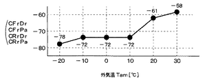
また、CFrDrは前席右側用補正係数であり、外気温Tamの関数として、図8に示すような予め設定されたマップにより与えられる。これは、乗員の着衣量を外気温Tamにより推定するものである。すなわち、外気温Tamが高くなると乗員は薄着になり、これにより、非接触温度センサ70aの検出値が体温の影響を受けて高めになるため、空調が涼しめに制御されることになる。そこで、この傾向を緩和するために、この補正係数CFrDrにより外気温Tamが高くなるほどTAOを低めに補正することにより、乗員の温熱感に、より適応した目標吹出温度TAOとすることができる。
Further, CFrDr is a front seat right side correction coefficient, which is given by a preset map as shown in FIG. 8 as a function of the outside air temperature Tam. This estimates the amount of occupant's clothes from the outside air temperature Tam. That is, when the outside air temperature Tam increases, the occupant becomes lightly worn, and the detected value of the
また、前席左側の空調ゾーン1bについても同様に、設定温度信号TsetFrPa、前席左側温度TirFrPa、外気温信号Tam、日射量信号TsPaを数式2に代入して、車室内に吹き出す空気の目標吹出温度TAOFrPaを算出する(ステップS123)。この目標吹出温度TAOFrPaは、前席左側(助手席)空調ゾーン1bの温度を設定温度TsetFrPaに維持するために必要な目標温度である。
Similarly, in the
TAOFrPa=KsetFrPa・TsetFrPa−KirFrPa・TirFrPa−Kam・Tam−KsPa・TsPa−CFrPa ・・・(数式2)
なお、KsetFrPaは前席左側用温度設定ゲイン(KsetFrPa=7.0)、KirFrPaは前席左側用IRゲイン(KirFrPa=3.0)、Kamは外気温ゲイン(Kam=1.1)、KsPaは左側日射ゲイン(KsPa=0.42)である。また、CFrPaは前席左側用補正係数であり、上記と同様、図8に示すマップで与えられる。
TAOFrPa = KsetFrPa.TsetFrPa-KirFrPa.TirFrPa-Kam.Tam-KsPa.TsPa-CFrPa (Formula 2)
KsetFrPa is the front seat left side temperature setting gain (KsetFrPa = 7.0), KirFrPa is the front seat left side IR gain (KirFrPa = 3.0), Kam is the outside air temperature gain (Kam = 1.1), and KsPa is The left solar radiation gain (KsPa = 0.42). CFrPa is a front seat left side correction coefficient, and is given by the map shown in FIG.
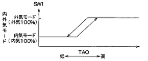
次に、TAOFrDr、TAOFrPaの平均値(以下、前席用目標平均値という)に基づいて、図9の制御マップにより、内外気モードを決定する(ステップS124)。なお、図9中、SW1は内外気切替ドア51の目標開度であり、この目標開度SW1を変化させて内気モード(内気100%)と外気モード(外気100%)とを連続的に切り替える。この内外気切替ドア51の切り替えにより、内気モード(内気循環モード)では、内気導入口50aより車室内空気(内気)を導入し、外気モード(外気導入モード)では、外気導入口50bより車室外空気(外気)を導入する。
Next, based on the average value of TAOFrDr and TAOFrPa (hereinafter referred to as the front seat target average value), the inside / outside air mode is determined by the control map of FIG. 9 (step S124). In FIG. 9, SW1 is the target opening degree of the inside / outside
具体的には、図9に示すように、TAOFrDr、TAOFrPaの平均値(図9中のTAOに相当する)が所定温度以下となる領域(最大冷房域)では、内外気切替ドア51により内気導入口50aを全開し、外気導入口50bを全閉する内気循環モードを選択し、TAOFrDr、TAOFrPaの平均値が所定温度より高くなると、内外気切替ドア51により外気導入口50bを全開し、内気導入口50aを全閉する外気導入モードを選択する。また、TAOFrDr、TAOFrPaの平均値(TAO)が両者の中間的な温度領域にあるときは内外気モードを内気と外気の両方が同時に導入される内外気混入モードとする。
Specifically, as shown in FIG. 9, in an area where the average value of TAOFrDr and TAOFrPa (corresponding to TAO in FIG. 9) is equal to or lower than a predetermined temperature (maximum cooling area), the inside / outside
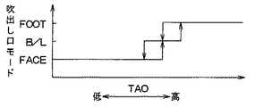
次に、図10により吹出口モードを前席側空調ゾーン1a、1bに対して個別に決定する(ステップS125)。図10は、予めROMに記憶されている吹出口モード決定の制御マップであって、本例では、TAOFrDr(図10中のTAOに相当する)が上昇するにつれて、空調ゾーン1aの吹出口モードをフェイス(FACE)モード→バイレベル(B/L)モード→フット(FOOT)モードと順次自動的に切り替える。また、TAOFrPa(図10中のTAOに相当する)が上昇するにつれて、空調ゾーン1bの吹出口モードをフェイス(FACE)モード→バイレベル(B/L)モード→フット(FOOT)モードと順次自動的に切り替えるようになっている。
Next, the outlet mode is individually determined for the front seat
ここで、フェイスモードとは、フェイス吹出口だけから空調風を吹き出すモードであり、フットモードとは、フット吹出口だけから空調風を吹き出しモードである。また、バイレベルモードとは、フェイス吹出口およびフット吹出口から空調風を吹き出すモードである。 Here, the face mode is a mode in which conditioned air is blown out only from the face outlet, and the foot mode is a mode in which conditioned air is blown out only from the foot outlet. The bi-level mode is a mode in which conditioned air is blown out from the face air outlet and the foot air outlet.
たとえば、フェイスモードでは、吹出口切替ドア56a(56b)にてフェイス吹出口2a(2b)を開口し、フェイス吹出口2a(2b)のみから空調風が車室内の乗員上半身側へ吹き出す。バイレベルモードでは、吹出口切替ドア56a(56b)にてフェイス吹出口2a(2b)およびフット吹出口(図示せず)を開口し、空調風がフェイス吹出口2a(2b)およびフット吹出口から車室内の乗員上半身側および乗員下半身側へ同時に吹き出す。フットモードでは、吹出口切替ドア(図示せず)にてフット吹出口を全開し、フット吹出口から主に空調風が車室内の乗員下半身側へ吹き出す。
For example, in the face mode, the
このように、空調ゾーン毎に吹出口モードを決定すると、各吹出口切替ドアのそれぞれのサーボモータを空調ゾーン毎に制御して、空調ゾーン毎にこの決定される吹出口モードとなるように各吹出口切替ドアをそれぞれ開閉させる。 As described above, when the air outlet zone is determined for each air conditioning zone, each servo motor of each air outlet switching door is controlled for each air conditioning zone so that the air outlet mode determined for each air conditioning zone is set. Open and close the air outlet switching doors.
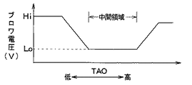
次に、上述の目標吹出温度TAOFrDr、TAOFrPaの平均値に基づいて、送風機モータ52aに印加するブロワ電圧を決定する(ステップS126)。このブロワ電圧としては、送風機52の風量を制御するためのもので、TAOFrDr、TAOFrPaの平均値に基づいて、予めROM内に記憶された図11の制御マップにしたがって決定されるものである。
Next, the blower voltage to be applied to the blower motor 52a is determined based on the average values of the target blowing temperatures TAOFrDr and TAOFrPa (step S126). This blower voltage is for controlling the air volume of the
図11の制御マップにおいて、図11中のTAOがTAOFrDr、TAOFrPaの平均値に相当し、この平均値(=TAO)が中間領域内にあるときには、ブロワ電圧(すなわち送風機52の風量)が一定値となり、TAOが中間領域より大きい場合にはこのTAOが大きくなるほどブロワ電圧(すなわち送風機52の風量)が大きくなる。また、TAOが中間領域より小さい場合にはTAOが小さくなるほどブロワ電圧(すなわち送風機52の風量)が小さくなる。このようにして、ブロワ電圧が決定される。 In the control map of FIG. 11, TAO in FIG. 11 corresponds to the average value of TAOFrDr and TAOFrPa, and when this average value (= TAO) is in the intermediate region, the blower voltage (that is, the air volume of the blower 52) is a constant value. When the TAO is larger than the intermediate region, the blower voltage (that is, the air volume of the blower 52) increases as the TAO increases. When TAO is smaller than the intermediate region, the blower voltage (that is, the air volume of the blower 52) decreases as TAO decreases. In this way, the blower voltage is determined.
次に、エアミックスドア55a、55bの目標開度θ1、θ2を次の数式3、4によって算出する(ステップS127)。
Next, target opening degrees θ1 and θ2 of the
θ1={(TAOFrDr−TeFr)/(Tw−TeFr)}×100(%) ・・・(数式3)
θ2={(TAOFrPa−TeFr)/(Tw−TeFr)}×100(%) ・・・(数式4)
なお、数式3、4において、TeFrは蒸発器温度センサ86の蒸発器吹出温度信号、Twは冷却水温度センサ82の冷却水(温水)温度信号である。θ1=0%およびθ2=0%は、最大冷房位置であり、運転席側通路50cおよび助手席側通路50dにおいて、前席側のエバポレータ53通過後の空気(冷風)の全量がバイパス通路51a、51bを流れる。また、θ1=100%およびθ2=100%は、最大暖房位置であり、運転席側通路50cおよび助手席側通路50dにおいて、前席側のエバポレータ53通過後の空気(冷風)の全量がコアヒータ54に流入して加熱される。
θ1 = {(TAOFrDr−TeFr) / (Tw−TeFr)} × 100 (%) (Formula 3)
θ2 = {(TAOFrPa−TeFr) / (Tw−TeFr)} × 100 (%) (Formula 4)
In Equations 3 and 4, TeFr is an evaporator outlet temperature signal of the
以上のように決定したブロワ電圧、目標開度θ1、θ2、内外気切替モード、吹出口モードのそれぞれを示す各制御信号をサーボモータ510a、550a、550b、560a、560bおよび送風機モータ52a等に出力して内外気切替ドア51、エアミックスドア55a、55b、吹出口切替ドア56a、56b、送風機52の各作動を制御する。(ステップS128)
その後、ステップS129で一定期間経過すると、ステップS121の処理に戻り、上述の空調制御処理(ステップS121〜S129)が繰り返される。このような演算、処理の繰り返しによって前席空調ゾーン1a、1bの空調が自動的に制御されることになる。
Control signals indicating the blower voltage, the target opening θ1, θ2, the inside / outside air switching mode, and the outlet mode determined as described above are output to the
Thereafter, when a certain period of time elapses in step S129, the process returns to step S121, and the above-described air conditioning control process (steps S121 to S129) is repeated. By repeating such calculation and processing, air conditioning in the front seat
(後席空調処理)
この場合、温度設定スイッチ11、12から設定温度信号TsetRrDr、TsetRrPaを読み込む(ステップS121)。さらに、外気温センサ81及び日射センサ83から外気温度信号Tam、日射量信号TsDr、TsPa、内気温度センサ85から内気温度TrRrを読み込むとともに、非接触温度センサ70c、70dから後席右側温度TirRrDr、後席左側温度TirRrPaを読み込む(ステップS122)。
(Rear seat air conditioning)
In this case, the set temperature signals TsetRrDr and TsetRrPa are read from the temperature setting switches 11 and 12 (step S121). Further, the outside air temperature signal Tam and the solar radiation amount signals TsDr and TsPa are read from the outside
そして、後席右側の空調ゾーン1cにおける設定温度信号TsetRrDr、後席右側温度TirRrDr、外気温信号Tam、日射量信号TsDrを、数式5に代入して、車室内に吹き出す空気の目標吹出温度TAORrDrを算出する(ステップS123)。この目標吹出温度TAORrDrは、車両環境条件(空調熱負荷条件)の変動にかかわらず、後席右側空調ゾーン1cの温度を設定温度TsetRrDrに維持するために必要な目標温度である。
Then, the set temperature signal TsetRrDr, the rear seat right temperature TirRrDr, the outside air temperature signal Tam, and the solar radiation amount signal TsDr in the
TAORrDr=KsetRrDr・TsetRrDr−KirRrDr・TirRrDr−KsDr・TsDr−Kam・Tam−CRrDr ・・・(数式5)
ここで、KsetRrDrは後席右側用温度設定ゲイン(KsetRrDr=7.0)、KirRrDrは後席右側用IRゲイン(KirRrDr=3.0)、Kamは外気温ゲイン(Kam=1.1)、KsDrは右側日射ゲイン(KsDr=0.42)である。また、CRrDrは後席右側用補正係数であり、上記と同様、図8に示すマップで与えられる。
TAORrDr = KsetRrDr.TsetRrDr-KirRrDr.TirRrDr-KsDr.TsDr-Kam.Tam-CRrDr (Formula 5)
Here, KsetRrDr is the rear seat right side temperature setting gain (KsetRrDr = 7.0), KirRrDr is the rear seat right side IR gain (KirRrDr = 3.0), Kam is the outside air temperature gain (Kam = 1.1), and KsDr. Is the right solar radiation gain (KsDr = 0.42). CRrDr is a rear seat right side correction coefficient, and is given by the map shown in FIG.
そして、後席左側の空調ゾーン1dにおける設定温度信号TsetRrPa、後席左側温度TirRrPa、外気温信号Tam、日射量信号TsPaを、数式6に代入して、車室内に吹き出す空気の目標吹出温度TAORrPaを算出する(ステップS123)。この目標吹出温度TAORrPaは、後席左側空調ゾーン1dの温度を設定温度TsetRrPaに維持するために必要な目標温度である。
Then, the set temperature signal TsetRrPa, the rear seat left side temperature TirRrPa, the outside air temperature signal Tam, and the solar radiation amount signal TsPa in the
TAORrPa=KsetRrPa・TsetRrPa−KirRrPa・TirRrPa−KsPa・TsPa−Kam・Tam+CRrPa ・・・(数式6)
ここで、KsetRrPaは後席左側用温度設定ゲイン(KsetRrPa=7.0)、KirRrPaは後席左側用IRゲイン(KirRrPa=3.0)、Kamは外気温ゲイン(Kam=1.1)、KsPaは左側日射ゲイン(KsPa=0.42)である。また、CRrPaは後席左側用補正係数であり、上記と同様、図8に示すマップで与えられる。
TAORrPa = KsetRrPa * TsetRrPa-KirRrPa * TirRrPa-KsPa * TsPa-Kam * Tam + CRrPa (Formula 6)
Here, KsetRrPa is the rear seat left side temperature setting gain (KsetRrPa = 7.0), KirRrPa is the rear seat left side IR gain (KirRrPa = 3.0), Kam is the outside air temperature gain (Kam = 1.1), and KsPa. Is the left solar radiation gain (KsPa = 0.42). CRrPa is a rear seat left side correction coefficient, and is given by the map shown in FIG.
次に、内外気モードの決定処理(ステップS124)を実行せずに(これは、後席空調では外気モードが設定されていないため)、吹出口モードの決定処理(ステップS125)を実行する。この吹出口モードの決定処理では、TAORrDr、TAORrPaに基づき、図9により吹出口モードを後席側の空調ゾーン1c、1dに対して個別に決定する。
Next, without determining the inside / outside air mode determination processing (step S124) (this is because the outside air mode is not set in the rear seat air conditioning), the air outlet mode determination processing (step S125) is executed. In this process for determining the air outlet mode, the air outlet mode is individually determined for the rear seat
具体的には、空調ゾーン1cの吹出口モードとしては、図10中のTAOをTAORrDrとし、このTAORrDrが上昇するにつれて吹出口モードをフェイス(FACE)モード→バイレベル(B/L)モード→フット(FOOT)モードと順次自動的に切り替える。また、空調ゾーン1dの吹出口モードとしては、図10中のTAOをTAORrPaとし、このTAORrPaが上昇するにつれて吹出口モードをフェイスモード→バイレベルモード→フットモードと順次自動的に切り替える。
Specifically, as the outlet mode of the
ここで、フェイスモードでは、吹出口切替ドア66a(66b)にてフェイス吹出口2c(2d)を開口し、フェイス吹出口2c(2d)のみから空調風が車室内の乗員上半身側へ吹き出す。バイレベルモードは、吹出口切替ドア66a(66b)にてフェイス吹出口2c(2d)およびフット吹出口(図示せず)を開口し、空調風がフェイス吹出口2c(2d)およびフット吹出口から車室内の乗員上半身側および乗員下半身側へ同時に吹き出す。フットモードは、吹出口切替ドア(図示せず)にてフット吹出口を全開し、フット吹出口から主に空調風が車室内の乗員下半身側へ吹き出す。
Here, in the face mode, the
次に、上述の目標吹出温度TAORrDr、TAORrPaの平均値(以下、後席用目標平均値という)を求め、この後席用目標平均値に基づき、図11の制御マップにしたがって、送風機モータ52aの場合と同様、送風機モータ62aに印加するブロワ電圧を決定する(ステップS126)。
Next, the average values of the target blowing temperatures TAORrDr and TAORrPa (hereinafter referred to as the rear seat target average value) are obtained, and based on the rear seat target average value, according to the control map of FIG. As in the case, the blower voltage to be applied to the
次に、エアミックスドア65a、65bの目標開度θ3、θ4を次の数式7、8によって算出する。なお、TeRrは蒸発器温度センサ87の蒸発器温度信号、Twは冷却水温度センサ82の冷却水温度信号である。
Next, target opening degrees θ3 and θ4 of the
θ3={(TAORrDr−TeRr)/(Tw−TeRr)}×100(%) ・・・(数式7)
θ4={(TAORrPa−TeRr)/(Tw−TeRr)}×100(%) ・・・(数式8)
なお、数式7、8において、TeRrは蒸発器温度センサ87の蒸発器温度信号、Twは冷却水温度センサ82の冷却水(温水)温度信号である。θ3=0%およびθ4=0%は、最大冷房位置であり、後席右側通路60cおよび後席左側通路60dにおいて、後席側のエバポレータ63通過後の空気(冷風)の全量がバイパス通路61a、61bを流れる。また、θ3=100%およびθ4=100%は、最大暖房位置であり、後席右側通路60cおよび後席左側通路60dにおいて、後席側のエバポレータ63通過後の空気(冷風)の全量がコアヒータ64に流入して加熱される。
θ3 = {(TAORrDr−TeRr) / (Tw−TeRr)} × 100 (%) (Formula 7)
θ4 = {(TAORrPa−TeRr) / (Tw−TeRr)} × 100 (%) (Equation 8)
In
以上のように決定したブロワ電圧、目標開度θ3、θ4、内外気切替モード、吹出モードのそれぞれを示す各制御信号を送風機モータ62aおよびサーボモータ650a、650b、660a、660b等に出力して送風機62、エアミックスドア65a、65b、吹出口切替ドア66a、66bの作動を制御する(ステップS128)。
Control signals indicating the blower voltage, target opening degrees θ3, θ4, the inside / outside air switching mode, and the blowing mode determined as described above are output to the
その後、ステップS129において一定期間経過すると、ステップS121の処理に戻り、上述の空調制御処理(ステップS121、S122、S123、S125〜S129)が繰り返される。このような処理の繰り返しによって後席の空調ゾーン1c、1dの空調が自動的に制御されることになる。
Thereafter, when a certain period of time elapses in step S129, the process returns to step S121, and the above-described air conditioning control process (steps S121, S122, S123, S125 to S129) is repeated. By repeating such processing, the air conditioning of the rear seat
以上説明したように、本第1実施形態では、前席右側および前席左側と、後席右側および後席左側との、それぞれに着座している乗員の、各サイドウインドウ側の肩の上部の温度を、それぞれの被検温範囲である肩の上方に配置した非接触温度センサ70a〜70dにより検出するので、各乗員の座高などの体格や姿勢の変化により肩の位置が天地方向に変動しても、検温対象である肩の上部は各非接触温度センサ70a〜70dの被検温範囲より外れることがなく、正確な乗員温度である肩上部温度を検出することができる。
As described above, in the first embodiment, the upper part of the shoulder on the side window side of the occupant seated on each of the right side of the front seat and the left side of the front seat, and the right side of the rear seat and the left side of the rear seat. Since the temperature is detected by the
また、それぞれサイドウインドウ側の肩の温度を検出して、これに基づき各空調ゾーンにおける目標吹出温度TAOを算出しているので、この目標吹出温度TAOには、側方からの日射の影響および冷輻射の影響を反映させることができる。さらに、この各空調ゾーンにおける目標吹出温度TAOの算出にあたり、外気温Tamに応じて各乗員の着衣量を推定しこれにより補正するので、内気温度を用いなくとも、乗員の温熱感を反映した適正な目標吹出温度TAOを算出することができる。 Further, the temperature of the shoulder on the side window side is detected, and the target blowout temperature TAO in each air conditioning zone is calculated based on the detected temperature. Therefore, the target blowout temperature TAO is affected by the effects of solar radiation from the side and cooling. The influence of radiation can be reflected. Furthermore, when calculating the target outlet temperature TAO in each air-conditioning zone, the amount of clothing of each occupant is estimated and corrected according to the outside air temperature Tam, so that it is appropriate to reflect the occupant's thermal feeling without using the inside air temperature. A target blowout temperature TAO can be calculated.
なお、乗員上方の車室内天井に非接触温度センサを配置しているので、従来のように、配置位置としてのシートのリクライニングによるセンサ位置の変化の影響も取り除くことができる。 In addition, since the non-contact temperature sensor is arranged on the vehicle interior ceiling above the occupant, it is possible to remove the influence of the change in the sensor position due to the reclining of the seat as the arrangement position as in the conventional case.
(他の実施形態)
第1実施形態では、図5に示すように、非接触温度センサ70a〜70dを、各乗員のサイドウインドウ側の肩の上方の天井に配置した例を示したが、これに限らず、次のように配置してもよい。なお、以下では、非接触温度センサ70a〜70dの配置形態のみが異なり、それ以外の構成(図1〜図4および図7〜図11)は全て上記第1実施形態と同じであるので、同一構成部分についての説明は省略する。
(Other embodiments)
In 1st Embodiment, as shown in FIG. 5, the example which has arrange | positioned the
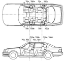
(1)図12に示すように、非接触温度センサ70a〜70dを、それぞれ、各乗員の着座中心位置よりもサイドウインドウ寄りであって、各乗員の着座中心位置よりも車両前方の天井に配置してもよい。これにより、非接触温度センサ70a〜70dは、それぞれ、乗員を斜め前方の上方から見ているので、各乗員の座高などの体格や姿勢の変化により肩の位置が天地方向に変動しても、検温対象である肩の上部は各非接触温度センサ70a〜70dの被検温範囲700a〜700dより外れることがなく、正確な乗員温度である肩上部温度を検出することができる。
(1) As shown in FIG. 12, the
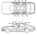
(2)図13に示すように、非接触温度センサ70a〜70dを、それぞれ、各乗員の着座中心位置よりもサイドウインドウ寄りであって、各乗員の着座中心位置よりも車両後方の天井に配置してもよい。これによっても、非接触温度センサ70a〜70dは、それぞれ、乗員を斜め後方の上方から見ているので、各乗員の座高などの体格や姿勢の変化により肩の位置が天地方向に変動しても、検温対象である肩の上部は各非接触温度センサ70a〜70dの被検温範囲700a〜700dより外れることがなく、正確な乗員温度である肩上部温度を検出することができる。また、非接触温度センサが乗員の視界から外れた位置に配置されているので、乗員は非接触温度センサに監視されているという感覚を解消でき、違和感をなくすことができる。
(2) As shown in FIG. 13, the
(3)図14に示すように、非接触温度センサ70a〜70dの被検温範囲700a〜700dを、各乗員の肩の上部だけでなく、その近傍の車室内装(例えば、ドアの内張り)をも含むように配置してもよい。すなわち、被検温範囲の中心を乗員の肩の上部のサイドウインドウ寄りとなるよう、あるいは、被検温範囲の乗員の顔側の端において、肩の上部が被検温範囲とされるよう設ける、すなわち、被検温範囲には顔部が含まれないように配置することができる。
(3) As shown in FIG. 14, the temperature ranges 700a to 700d of the
これは、上記図4において、非接触温度センサ70a〜70dの検知部71aと窓71dとの間隔Sをやや短く設定して、被検温範囲(視野範囲)を大きくすることにより、構成することができる。あるいは、非接触温度センサ70a〜70dの視界方向を、第1実施形態の場合よりもややサイドウインドウ側に傾けるように配置することによっても、構成することができる。
This can be configured by setting the interval S between the
このように、非接触温度センサ70a〜70dの被検温範囲700a〜700dを、乗員の肩上部およびその近傍の車室内装を含むように設定することにより、非接触温度センサにより検出する温度には、乗員の肩上部の温度と、内装温度とをともに含むので、内装からの輻射も検出温度に反映させることができる。したがって、このように検出した非接触温度センサによる温度に基づき算出する目標吹出温度TAOには、乗員の温度に車室内装からの輻射の影響が考慮されるので、乗員の温熱感に応じた空調状態を実現できる。
In this way, by setting the temperature ranges 700a to 700d of the
また、非接触温度センサ70a〜70dの被検温範囲700a〜700dの中心をサイドウインドウ寄りに設定し、被検温範囲700a〜700dの乗員の顔側の端において、肩の上部が被検温範囲とされるよう設けることにより、被検温範囲700a〜700dには乗員の顔部が含まれないようにすることができる。したがって、被検温範囲700a〜700dから頭髪の多寡や長さなど個人差が大きい顔部を除くことができ、乗員の個人差に影響されず、安定した乗員温度の検出が可能になる。
(4)図15に示すように、非接触温度センサ70a〜70dの被検温範囲700a〜700dを、各乗員の肩の上部だけでなく、その近傍のサイドウインドウをも含むように配置してもよい。
Further, the centers of the
(4) As shown in FIG. 15, the temperature ranges 700a to 700d of the
これは、上記図4において、非接触温度センサ70a〜70dの窓71dを所望の形状とし、検知部71aと窓71dとの間隔Sをやや短く設定して被検温範囲(視野範囲)を大きくすることにより、構成することができる。また、非接触温度センサ70a〜70dの視界方向を、第1実施形態の場合よりもややサイドウインドウ側に傾けるように配置するする。
In FIG. 4, the
このように、非接触温度センサ70a〜70dの被検温範囲700a〜700dを、乗員の肩上部およびその近傍のサイドウインドウを含むように設定することにより、非接触温度センサ70a〜70dにより検出する温度には、乗員の肩上部の温度と、内装温度およびサイドウインドウの温度とを、ともに含むので、内装からの輻射およびサイドウインドウからの輻射(冬季にあっては、特に冷輻射の影響)も検出温度に反映させることができる。したがって、このように検出した非接触温度センサによる温度に基づき算出する目標吹出温度TAOには、乗員の温度に車室内装からの輻射の影響が考慮されるので、乗員の温熱感に応じた空調状態を実現できる。
Thus, the temperature detected by the
1a、1b、1c、1d…空調ゾーン、5…前席空調システム、
6…後席空調システム、70a、70b、70c、70d…非接触温度センサ、
8…エアコンECU。
1a, 1b, 1c, 1d ... air conditioning zone, 5 ... front seat air conditioning system,
6 ... Rear seat air conditioning system, 70a, 70b, 70c, 70d ... Non-contact temperature sensor,
8: Air conditioner ECU.
Claims (8)
前記非接触温度センサにより検出された温度に基づいて前記車室内の空調状態を調整する空調手段(5、6、8)と、
を備えることを特徴とする車両用空調装置。 In the passenger compartment (1), it is located above the seating position of the occupant and closer to the side window near the seating position than the center of the seating position, and has a predetermined temperature range (700a, 700b, 700c, 700d). A non-contact temperature sensor (70a, 70b, 70c, 70d) that is provided so as to include at least the upper part of the shoulder of the occupant on the side window side and detects the temperature of the temperature range to be detected in a non-contact manner;
Air-conditioning means (5, 6, 8) for adjusting the air-conditioning state of the vehicle interior based on the temperature detected by the non-contact temperature sensor;
A vehicle air conditioner comprising:
The air conditioning means calculates a target blowing temperature based on the temperature detected by the non-contact temperature sensor, and adjusts an air conditioning state of the temperature range to be detected based on the target blowing temperature. The vehicle air conditioner according to any one of 7.
Priority Applications (2)
| Application Number | Priority Date | Filing Date | Title |
|---|---|---|---|
| JP2004120337A JP2005297902A (en) | 2004-04-15 | 2004-04-15 | Air conditioner for vehicles |
| US10/946,509 US20050098640A1 (en) | 2003-11-10 | 2004-09-21 | Temperature detection device and vehicle air conditioner using the same |
Applications Claiming Priority (1)
| Application Number | Priority Date | Filing Date | Title |
|---|---|---|---|
| JP2004120337A JP2005297902A (en) | 2004-04-15 | 2004-04-15 | Air conditioner for vehicles |
Publications (1)
| Publication Number | Publication Date |
|---|---|
| JP2005297902A true JP2005297902A (en) | 2005-10-27 |
Family
ID=35329956
Family Applications (1)
| Application Number | Title | Priority Date | Filing Date |
|---|---|---|---|
| JP2004120337A Withdrawn JP2005297902A (en) | 2003-11-10 | 2004-04-15 | Air conditioner for vehicles |
Country Status (1)
| Country | Link |
|---|---|
| JP (1) | JP2005297902A (en) |
Cited By (4)
| Publication number | Priority date | Publication date | Assignee | Title |
|---|---|---|---|---|
| JP2017030377A (en) * | 2015-07-29 | 2017-02-09 | 株式会社デンソー | Control device |
| CN110901331A (en) * | 2018-09-17 | 2020-03-24 | 日盈汽车电子(上海)有限公司 | In-vehicle temperature management system based on vehicle-mounted infrared sensor and management method thereof |
| CN110901333A (en) * | 2018-09-17 | 2020-03-24 | 日盈汽车电子(上海)有限公司 | Air conditioner control system and air conditioner sensing control method |
| CN120134891A (en) * | 2025-05-15 | 2025-06-13 | 中汽研汽车检验中心(宁波)有限公司 | A vehicle air conditioning intelligent control method and system |
-
2004
- 2004-04-15 JP JP2004120337A patent/JP2005297902A/en not_active Withdrawn
Cited By (4)
| Publication number | Priority date | Publication date | Assignee | Title |
|---|---|---|---|---|
| JP2017030377A (en) * | 2015-07-29 | 2017-02-09 | 株式会社デンソー | Control device |
| CN110901331A (en) * | 2018-09-17 | 2020-03-24 | 日盈汽车电子(上海)有限公司 | In-vehicle temperature management system based on vehicle-mounted infrared sensor and management method thereof |
| CN110901333A (en) * | 2018-09-17 | 2020-03-24 | 日盈汽车电子(上海)有限公司 | Air conditioner control system and air conditioner sensing control method |
| CN120134891A (en) * | 2025-05-15 | 2025-06-13 | 中汽研汽车检验中心(宁波)有限公司 | A vehicle air conditioning intelligent control method and system |
Similar Documents
| Publication | Publication Date | Title |
|---|---|---|
| JP4591133B2 (en) | Air conditioner for vehicles | |
| JP3861793B2 (en) | Air conditioner for vehicles | |
| JP4114651B2 (en) | Air conditioner for vehicles | |
| US20050098640A1 (en) | Temperature detection device and vehicle air conditioner using the same | |
| JP2010143374A (en) | Air conditioner for vehicle | |
| JP2005297902A (en) | Air conditioner for vehicles | |
| JP2003146055A (en) | Vehicle air conditioner | |
| JP2005329929A (en) | VEHICLE TEMPERATURE DETECTION DEVICE AND VEHICLE AIR CONDITIONER | |
| JP4277722B2 (en) | Air conditioner for vehicles | |
| JP4259258B2 (en) | Air conditioner for vehicles | |
| JP4269905B2 (en) | Air conditioner for vehicles | |
| JP2005306095A (en) | Air conditioning control device for vehicles | |
| JP2004330961A (en) | Vehicle air conditioner | |
| JP2006240578A (en) | Vehicle seating determination device and vehicle air conditioner | |
| JP2005138775A (en) | VEHICLE TEMPERATURE DETECTION DEVICE AND VEHICLE AIR CONDITIONER | |
| JP4812416B2 (en) | Air conditioner for vehicles | |
| JP2005140571A (en) | Non-contact temperature sensor for vehicle and air conditioner for vehicle | |
| JP2005147556A (en) | VEHICLE TEMPERATURE DETECTION DEVICE AND VEHICLE AIR CONDITIONER | |
| JP4196783B2 (en) | Air conditioner for vehicles | |
| JP4207709B2 (en) | Air conditioner for vehicles | |
| JP4207708B2 (en) | Air conditioner for vehicles | |
| JP2005297903A (en) | VEHICLE TEMPERATURE DETECTION DEVICE AND VEHICLE AIR CONDITIONER | |
| JP4120613B2 (en) | VEHICLE TEMPERATURE DETECTING DEVICE AND VEHICLE AIR CONDITIONER | |
| JP2009214675A (en) | Air conditioner for vehicle | |
| JP2005145133A (en) | Air conditioner for vehicles |
Legal Events
| Date | Code | Title | Description |
|---|---|---|---|
| A621 | Written request for application examination |
Free format text: JAPANESE INTERMEDIATE CODE: A621 Effective date: 20060606 |
|
| A761 | Written withdrawal of application |
Effective date: 20080507 Free format text: JAPANESE INTERMEDIATE CODE: A761 |