JP2005297834A - Foldable seat structure for vehicles - Google Patents
Foldable seat structure for vehicles Download PDFInfo
- Publication number
- JP2005297834A JP2005297834A JP2004118694A JP2004118694A JP2005297834A JP 2005297834 A JP2005297834 A JP 2005297834A JP 2004118694 A JP2004118694 A JP 2004118694A JP 2004118694 A JP2004118694 A JP 2004118694A JP 2005297834 A JP2005297834 A JP 2005297834A
- Authority
- JP
- Japan
- Prior art keywords
- seat
- link
- seat cushion
- rail
- vehicle body
- Prior art date
- Legal status (The legal status is an assumption and is not a legal conclusion. Google has not performed a legal analysis and makes no representation as to the accuracy of the status listed.)
- Pending
Links
Images
Landscapes
- Seats For Vehicles (AREA)
Abstract
【課題】 簡単なリンク構成でシートクッションの格納性を向上する。
【解決手段】 リヤシート10のシートクッション18は、シートレール20によってフロアパネル14に移動可能に取付けられており、シートクッション18はアッパレール24に対して着脱可能となっている。シートクッション18は第1リンク28を介してフロアパネル14の凹部16に連結されており、シートクッション18とシートバック19は第2リンク38を介して連結されている。
【選択図】 図1PROBLEM TO BE SOLVED: To improve the storage performance of a seat cushion with a simple link configuration.
SOLUTION: A seat cushion 18 of a rear seat 10 is movably attached to a floor panel 14 by a seat rail 20, and the seat cushion 18 is detachable from an upper rail 24. The seat cushion 18 is connected to the recess 16 of the floor panel 14 via the first link 28, and the seat cushion 18 and the seat back 19 are connected via the second link 38.
[Selection] Figure 1
Description
本発明は車両用可倒シート構造に関し、特に、自動車等の車体に適用される車両用可倒シート構造に関する。 The present invention relates to a retractable seat structure for a vehicle, and more particularly to a retractable seat structure for a vehicle applied to a vehicle body such as an automobile.
従来から、自動車等の車体に適用される車両用可倒シート構造においては、リヤシートを前方の格納方向へ移動すると、第1リンクが軸を中心に前方へ揺動するようになっており、リヤシートの第1リンクが前方へ所定角度揺動すると、第1リンクと第2リンクとの連結部に配設されたフックが、ストライカの丸棒部から外れ、第2リンクが軸を中心に前方へ揺動するようになっている。このため、リヤシートが車両前方のフロア面上の格納位置へ移動する際のシート回転半径が小さくなり、シート格納性を向上した構成が知られている(例えば、特許文献1参照)。
しかしながら、特許文献1のような車両用可倒シート構造では、リヤシートのシートクッションの前部とフロアとを連結するリンクが、第1リンクと第2リンクとで構成されている。この結果、リンクの構成が複雑で長くなる。 However, in the retractable seat structure for a vehicle as disclosed in Patent Document 1, the link that connects the front portion of the seat cushion of the rear seat and the floor is composed of the first link and the second link. As a result, the link configuration is complicated and long.
本発明は上記事実を考慮し、簡単なリンク構成でシートクッションの格納性を向上できる車両用可倒シート構造を提供することが目的である。 In view of the above facts, an object of the present invention is to provide a retractable seat structure for a vehicle that can improve the retractability of a seat cushion with a simple link configuration.
請求項1記載の本発明の車両用可倒シート構造は、シートクッションの後部に回転可能に配設されたシートバックと、
車体に固定されたアンダレールと、該アンダレールに対してスライド可能とされ、シートクッションが着脱可能に取付けられたアッパレールと、から成るシートレールと、
一方の端部がシートクッションに回転可能に連結され、他方の端部がフロアに回転可能に連結された第1リンクと、
一方の端部がシートクッションに結合され、他方の端部がシートバックに回転可能に連結された第2リンクと、
を有することを特徴とする。
The retractable seat structure for a vehicle according to the first aspect of the present invention includes a seat back rotatably disposed at a rear portion of a seat cushion,
A seat rail comprising: an under rail fixed to the vehicle body; an upper rail that is slidable with respect to the under rail; and a seat cushion is detachably attached;
A first link having one end rotatably connected to the seat cushion and the other end rotatably connected to the floor;
A second link having one end coupled to the seat cushion and the other end rotatably coupled to the seat back;
It is characterized by having.
従って、シートを格納する際には、車体に固定されたシートレールのアンダレールに対してスライド可能とされたシートレールのアッパレールをシートクッションの格納方向へスライドさせる。その際、一方の端部がシートクッションに回転可能に連結され、他方の端部がフロアに回転可能に連結された第1リンクが回転し、シートクッションが格納方向へ移動する。その後、シートクッションをアッパレールから外し、シートクッションの後部に回転可能に配設されたシートバックを格納方向へ回転することで、第1リンクが回転すると共に、一方の端部がシートクッションに結合され、他方の端部がシートバックに回転可能に連結された第2リンクが回転することによって、シートクッションを格納位置へ移動することができる。この結果、格納する際のシートクッションの車体前方への回転移動量を短くできる。このため、簡単なリンク構成でシートクッションの格納性を向上できる。 Therefore, when the seat is stored, the upper rail of the seat rail which is slidable with respect to the under rail of the seat rail fixed to the vehicle body is slid in the storing direction of the seat cushion. At that time, the first link having one end rotatably connected to the seat cushion and the other end rotatably connected to the floor rotates, and the seat cushion moves in the retracting direction. Thereafter, the seat cushion is removed from the upper rail, and the seat back disposed rotatably at the rear portion of the seat cushion is rotated in the retracted direction, whereby the first link rotates and one end portion is coupled to the seat cushion. The seat cushion can be moved to the retracted position by rotating the second link whose other end is rotatably connected to the seat back. As a result, the amount of rotational movement of the seat cushion to the front of the vehicle body when stored can be shortened. For this reason, the retractability of the seat cushion can be improved with a simple link configuration.
請求項1記載の本発明の車両用可倒シート構造は、シートクッションの後部に回転可能に配設されたシートバックと、車体に固定されたアンダレールと、アンダレールに対してスライド可能とされ、シートクッションが着脱可能に取付けられたアッパレールと、から成るシートレールと、一方の端部がシートクッションに回転可能に連結され、他方の端部がフロアに回転可能に連結された第1リンクと、一方の端部がシートクッションに結合され、他方の端部がシートバックに回転可能に連結された第2リンクと、を有するため、簡単なリンク構成でシートクッションの格納性を向上できるという優れた効果を有する。 The retractable seat structure for a vehicle according to the first aspect of the present invention is configured such that a seat back rotatably disposed at a rear portion of a seat cushion, an under rail fixed to the vehicle body, and a slide with respect to the under rail. An upper rail to which the seat cushion is detachably attached, and a first link having one end rotatably connected to the seat cushion and the other end rotatably connected to the floor. The first link is connected to the seat cushion, and the other end is rotatably connected to the seat back. Therefore, the seat cushion can be easily stored with a simple link configuration. It has the effect.
本発明における車両用可倒シート構造の一実施形態を図1〜図4に従って説明する。 One embodiment of a vehicle retractable seat structure according to the present invention will be described with reference to FIGS.
なお、図中矢印FRは車体前方方向を、矢印UPは車体上方方向を示す。 In the figure, the arrow FR indicates the vehicle body front direction, and the arrow UP indicates the vehicle body upward direction.
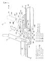
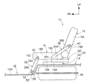
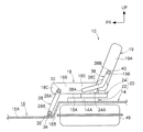
図1に示される如く、本実施形態の車両用可倒シートはフロントシート12の車体後方側に配設されたリヤシート10である。また、フロアパネル14におけるリヤシート10の配設部14Aと、フロントシート12の配設部14Bとの間にはリヤシート10を格納できる凹部16が形成されている。
As shown in FIG. 1, the vehicle retractable seat of the present embodiment is a
なお、リヤシート10のシートクッション18の後端部には、周知の回転機構によってシートバック19が車体前後方向へ回転可能に配設されている。
A
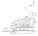
図2に示される如く、フロアパネル14におけるリヤシート10の配設部14Aには、車体前後方向に沿ってシートレール20のアンダレール22が取付けられており、シートレール20のアッパレール24は、アンダレール22に対して車体前方(図2の矢印A方向)と車体後方(図2の矢印B方向)へ移動(スライド)可能となっている。
As shown in FIG. 2, an under
シートレール20のアッパレール24の前部24Aには、シートクッション18の下部18Aの後部が着脱可能に取付けられており、シートクッション18はアッパレール24とともに車体前後方向へ移動可能となっている。
A
シートクッション18の側部18Bの前部18Cには、直線状とされた第1リンク28の一方の端部である上端部28Aが軸30によって回転可能に軸支されている。第1リンク28の他方の端部である下端部28Bは、フロアパネル14に形成した凹部16の底部16Aにおける後端部である縦壁部16Bの近傍に固定されたブラケット32に軸34によって回転可能に支持されている。
An
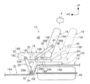
従って、図3に示される如く、リヤシート10のスライドロックを外し、リヤシート10を図3に2点鎖線で示す後方の位置から、車体前方(図3の矢印A方向)へ押圧すると、シートレール20のアッパレール24がアンダレール22に対して車体前方へスライドすると共に、第1リンク28が軸34を中心に車体前方(図3の矢印C方向)へ回転することで、リヤシート10が図3に2点鎖線で示す後方の位置から車体前方へ移動し、図3に実線で示す前方の位置へ移動するようになっている。即ち、シートレール20と第1リンク28とによってリヤシート10がスライド運動するようになっている。
Accordingly, as shown in FIG. 3, when the
図2に示される如く、シートクッション18の側部18Bの後部18Dには、直線状とされた第2リンク38の一方の端部である前端部38Aが固定されており、第2リンク38の他方の端部である後端部38Bは、シートバック19の側部19Aの下部19Bに軸40によって回転可能に支持されている。
As shown in FIG. 2, a
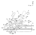
従って、図4に2点鎖線で示す前方の位置において、リヤシート10のシートバック19のロックを外し、シートバック19を図4に2点鎖線で示す起立位置から、車体前方(図4の矢印A方向)へ押圧することで、シートバック19が車体前方(図4の矢印D方向)へ回転し、図4に実線で示す前倒位置へ移動する。この際、第1リンク28が軸34を中心に車体前方(図4の矢印C方向)へ回転し、且つ、第2リンク38が軸40を中心に回転することで、シートクッション18が、図4に2点鎖線で示す通常使用位置から車体前方下側へ移動し、図4に実線で示す凹部16内の格納位置へ移動するようになっている。即ち、第1リンク28と第2リンク38とによってリヤシート10がチルトダウン運動するようになっている。
Accordingly, the
なお、図4に示される如く、第1リンク28の長さ及び第2リンク38の長さは、シートクッション18を凹部16内の格納位置へ確実に移動でき、且つ、格納する際のシートクッション18の車体前方へのストロークを短くできる長さに設定されている。また、アッパレール24の前端部24Bの位置は、格納位置にあるシートクッション18と干渉しない位置に設定されている。
As shown in FIG. 4, the length of the
次に、本実施形態の作用を説明する。 Next, the operation of this embodiment will be described.
本実施形態では、リヤシート10を格納する際に、リヤシート10のスライドロックを外し、リヤシート10を図3に2点鎖線で示す後方の位置から、車体前方(図3の矢印A方向)へ押圧すると、シートレール20のアッパレール24がアンダレール22に対して車体前方へスライドすると共に、第1リンク28が軸34を中心に車体前方(図3の矢印C方向)へ回転することで、リヤシート10が図3に2点鎖線で示す後方の位置から車体前方へ移動し、図3に実線で示す前方の位置へ移動する。
In the present embodiment, when the
次に、図4に2点鎖線で示す前方の位置において、リヤシート10のシートバック19のロックを外し、シートバック19を図4に2点鎖線で示す起立位置から、車体前方(図4の矢印A方向)へ押圧すると、シートバック19が車体前方(図4の矢印D方向)へ回転し、図4に実線で示す前倒位置へ移動する。この際、第1リンク28が軸34を中心に車体前方(図4の矢印C方向)へ回転し、且つ、第2リンク38が軸40を中心に回転することで、シートクッション18が、図4に2点鎖線で示す通常使用位置から車体前方下側へ移動し、図4に実線で示す凹部16内の格納位置へ移動する。
Next, the
この結果、本実施形態では、リヤシート10のシートクッション18を凹部16に格納するためのリンク機構が、第1リンク28と第2リンク38となら成る簡単な構成であると共に、格納する際のシートクッション18の車体前方への回転移動量を少なくできる。
As a result, in the present embodiment, the link mechanism for storing the
従って、フロントシート12を車体前方へ移動しなくても、リヤシート10のシートクッション18をフロントシート12と干渉することなく、フロアパネル14の凹部16に格納できる。このため、簡単なリンク構成でシートクッション18の格納性を向上できる。
Therefore, the
また、本実施形態では、図1に実線で示すリヤシート10の格納状態において、シートクッション18を凹部16に格納することで、シートバック19の格納位置を車室下方側に設定できる。この結果、格納したシートバック19の上方における車室内空間48の高さを、シートレール20とシートバック19との間にシートクッション18を挟んで格納する構成と同じにする場合には、シートレール20の配設位置を車体上方に設定できる。このため、フロアパネル14におけるリヤシート10の配設部14Aの下に燃料タンク49、サスペンション、排気管等の配設スペースを確保し易くなる。
Further, in the present embodiment, in the retracted state of the
以上に於いては、本発明を特定の実施形態について詳細に説明したが、本発明は上記実施形態に限定されるものではなく、本発明の範囲内にて他の種々の実施形態が可能であることは当業者にとって明らかである。例えば、上記実施形態では、第1リンク28の下端部28Bを、フロアパネル14に形成した凹部16の底部16Aにおける後端部の近傍に固定されたブラケット32に軸34によって回転可能に支持したが、これに代えて、図5に示される如く、第1リンク28の下端部28Bを、フロアパネル14に形成した凹部16の縦壁部16Bの下部に固定されたブラケット50に軸52によって回転可能に支持した構成としても良い。
Although the present invention has been described in detail with respect to specific embodiments, the present invention is not limited to the above-described embodiments, and various other embodiments are possible within the scope of the present invention. It will be apparent to those skilled in the art. For example, in the above embodiment, the
また、上記実施形態では、第2リンク38を直線状としたが、これに代えて、図6に示される如く、第2リンク38をシートクッション18の側部18Bとシートバック19の側部19Aとに沿って延設された側面視く字状のリンクとすることで、第2リンク38の中間部38Cがシートクッション18の上方に突出し難い構成としても良い。
In the above embodiment, the
また、上記実施形態では、本発明の車両用可倒シート構造をリヤシート10に適用したが、本発明の車両用可倒シート構造はリヤシート10以外のシートにも適用可能である。
Further, in the above embodiment, the vehicle retractable seat structure of the present invention is applied to the
10 リヤシート(シート)
14 フロアパネル
16 フロアパネルの凹部
18 シートクッション
19 シートバック
20 シートレール
22 シートレールのアンダレール
24 シートレールのアッパレール
28 第1リンク
38 第2リンク
10 Rear seat (seat)
DESCRIPTION OF
Claims (1)
車体に固定されたアンダレールと、該アンダレールに対してスライド可能とされ、シートクッションが着脱可能に取付けられたアッパレールと、から成るシートレールと、
一方の端部がシートクッションに回転可能に連結され、他方の端部がフロアに回転可能に連結された第1リンクと、
一方の端部がシートクッションに結合され、他方の端部がシートバックに回転可能に連結された第2リンクと、
を有することを特徴とする車両用可倒シート構造。 A seat back rotatably disposed at the rear of the seat cushion;
A seat rail comprising: an under rail fixed to the vehicle body; an upper rail that is slidable with respect to the under rail; and a seat cushion is detachably attached;
A first link having one end rotatably connected to the seat cushion and the other end rotatably connected to the floor;
A second link having one end coupled to the seat cushion and the other end rotatably coupled to the seat back;
A retractable seat structure for a vehicle, comprising:
Priority Applications (1)
| Application Number | Priority Date | Filing Date | Title |
|---|---|---|---|
| JP2004118694A JP2005297834A (en) | 2004-04-14 | 2004-04-14 | Foldable seat structure for vehicles |
Applications Claiming Priority (1)
| Application Number | Priority Date | Filing Date | Title |
|---|---|---|---|
| JP2004118694A JP2005297834A (en) | 2004-04-14 | 2004-04-14 | Foldable seat structure for vehicles |
Publications (1)
| Publication Number | Publication Date |
|---|---|
| JP2005297834A true JP2005297834A (en) | 2005-10-27 |
Family
ID=35329896
Family Applications (1)
| Application Number | Title | Priority Date | Filing Date |
|---|---|---|---|
| JP2004118694A Pending JP2005297834A (en) | 2004-04-14 | 2004-04-14 | Foldable seat structure for vehicles |
Country Status (1)
| Country | Link |
|---|---|
| JP (1) | JP2005297834A (en) |
Cited By (2)
| Publication number | Priority date | Publication date | Assignee | Title |
|---|---|---|---|---|
| US7452019B1 (en) | 2007-06-05 | 2008-11-18 | Toyota Motor Engineering & Manufacturing North America, Inc. | Sliding and stowing motor vehicle seat |
| WO2014168233A1 (en) * | 2013-04-12 | 2014-10-16 | 本田技研工業株式会社 | Vehicular seat device |
-
2004
- 2004-04-14 JP JP2004118694A patent/JP2005297834A/en active Pending
Cited By (4)
| Publication number | Priority date | Publication date | Assignee | Title |
|---|---|---|---|---|
| US7452019B1 (en) | 2007-06-05 | 2008-11-18 | Toyota Motor Engineering & Manufacturing North America, Inc. | Sliding and stowing motor vehicle seat |
| WO2014168233A1 (en) * | 2013-04-12 | 2014-10-16 | 本田技研工業株式会社 | Vehicular seat device |
| JP5961322B2 (en) * | 2013-04-12 | 2016-08-02 | 本田技研工業株式会社 | Vehicle seat device |
| US9643519B2 (en) | 2013-04-12 | 2017-05-09 | Honda Motor Co., Ltd. | Vehicular seat device |
Similar Documents
| Publication | Publication Date | Title |
|---|---|---|
| EP1454788B1 (en) | Seat storing structure for a vehicle and vehicle provided therewith | |
| JPH11342748A (en) | Convertible car 3-fold folding roof | |
| JP4108503B2 (en) | Vehicle open roof storage structure | |
| JP6262575B2 (en) | Vehicle seat | |
| JPH1086739A (en) | Lift device for wheelchair in vehicle | |
| JP2008150044A (en) | Vehicle seat structure | |
| JP4227896B2 (en) | Automotive rear panel with folding roof | |
| CN100364808C (en) | Seat device for vehicle | |
| JP2008273445A (en) | Vehicle headrest tilting device | |
| JP4013858B2 (en) | Storage structure for vehicle seat | |
| JP2001239870A (en) | Underfloor storage seat structure | |
| JP4626402B2 (en) | Rear cargo compartment structure for vehicles | |
| JP2008273399A (en) | Cargo board interlocking structure | |
| JP2007185987A (en) | Retractable rearview mirror device | |
| JP3976240B2 (en) | Vehicle seat | |
| JP2007203757A (en) | Sheet storage structure | |
| JP2000142476A (en) | Rear body structure of vehicle | |
| JP4442451B2 (en) | Vehicle seat | |
| JP2002219978A (en) | Vehicle seat | |
| JP4079052B2 (en) | Storage structure for vehicle seat | |
| JP2007082616A (en) | Vehicle seat | |
| JP2000229527A (en) | Automotive seat structure | |
| JP5187660B2 (en) | Car seat | |
| JP2007284060A (en) | Vehicle seat structure | |
| JP3885117B2 (en) | Car retractable slide seat |
Legal Events
| Date | Code | Title | Description |
|---|---|---|---|
| A621 | Written request for application examination |
Free format text: JAPANESE INTERMEDIATE CODE: A621 Effective date: 20060719 |
|
| A131 | Notification of reasons for refusal |
Free format text: JAPANESE INTERMEDIATE CODE: A131 Effective date: 20080108 |
|
| A02 | Decision of refusal |
Effective date: 20080507 Free format text: JAPANESE INTERMEDIATE CODE: A02 |