JP2007284060A - Seat structure for vehicle - Google Patents
Seat structure for vehicle Download PDFInfo
- Publication number
- JP2007284060A JP2007284060A JP2007204264A JP2007204264A JP2007284060A JP 2007284060 A JP2007284060 A JP 2007284060A JP 2007204264 A JP2007204264 A JP 2007204264A JP 2007204264 A JP2007204264 A JP 2007204264A JP 2007284060 A JP2007284060 A JP 2007284060A
- Authority
- JP
- Japan
- Prior art keywords
- seat
- seat cushion
- vehicle
- vehicle body
- storage recess
- Prior art date
- Legal status (The legal status is an assumption and is not a legal conclusion. Google has not performed a legal analysis and makes no representation as to the accuracy of the status listed.)
- Pending
Links
Images


Abstract
Description
本発明は、シート不使用時に、車体フロアに形成した収納凹部に収納可能な車両用シート構造に関する。 The present invention relates to a vehicle seat structure that can be stored in a storage recess formed in a vehicle body floor when the seat is not used.
従来より、この種の車両用シート構造として、例えば、特許文献1に開示されるように、乗用車の車体フロアにシート収納用の凹部を設け、シートバックとシートクッションとからなるシートを、上記収納凹部に揺動自在に配設したものが知られている。このものでは、シート使用状態でのシートクッション底面後端部が収納凹部の開口前縁に連結用ヒンジを介して揺動自在に連結されており、シート不使用時には、まず、シートバックをシートクッション側に折り畳み、それらを一体に揺動させて収納凹部に収納する。この収納状態では、シートクッションの底面が車体フロアと面一になるような構造になっていて、荷物が置き易くなる等、使い勝手の向上が図られている。
ところが、上記従来の車両用シート構造では、シートクッションを車体フロアに連結用ヒンジにより連結する構造であるため、車体フロアでのシートのレイアウト上の制約が大きいという不具合がある。すなわち、例えばシート使用時のシートクッションと車体フロアとの間のクリアランスを大きめに設定しようとすれば、連結用ヒンジ自体が大きくなって車体フロア上に突出してしまい、荷物を置くときに妨げとなる。 However, the conventional vehicle seat structure has a problem in that the seat cushion is connected to the vehicle body floor by the connecting hinge, and thus there is a great restriction on the layout of the seat on the vehicle body floor. That is, for example, if the clearance between the seat cushion and the vehicle body floor when using the seat is set to be large, the connecting hinge itself becomes large and protrudes on the vehicle body floor, which hinders the placement of luggage. .
また、上記従来の車両用シート構造では、シートの収納時において、シートクッションの底面が車体フロアと面一になるが、該シートクッションの下側にシートバックが収納されるので、このシートバックに収納凹部の底に溜まっているゴミや埃等が付着し易くなり、シートの使用感を損ねるという不具合もある。 In the conventional vehicle seat structure, when the seat is stored, the bottom surface of the seat cushion is flush with the vehicle body floor, but the seat back is stored under the seat cushion. There is also a problem that dust, dust, and the like accumulated at the bottom of the storage recess are likely to adhere, which impairs the feeling of use of the sheet.
本発明は、斯かる諸点に鑑みてなされたものであり、その目的とするところは、シートと車体側との連結構造に工夫を凝らすことで、シートのレイアウト上の制約を緩和するとともに、その使用感の向上を図ることにある。 The present invention has been made in view of such various points, and the object of the present invention is to reduce restrictions on the layout of the seat by devising a connection structure between the seat and the vehicle body, The purpose is to improve the feeling of use.
上記目的を達成するために、本発明の解決手段では、シートをリンク部材によって車体側に連結することで、レイアウト上の制約を緩和するようにした。 In order to achieve the above object, in the solution means of the present invention, the seat is connected to the vehicle body side by a link member, thereby relaxing the constraints on the layout.
具体的には、請求項1記載の発明は、シートクッションとシートバックとからなるシートを、使用状態から、その後方の車体フロアに形成した収納凹部に移動させて収納可能とした車両用シート構造を対象とする。
Specifically, the invention according to
そして、上記シートが、車両前後方向における最後列のシートである場合に、一端部が上記シートクッションの後側の部位に回転自在に連結される一方、他端部が上記収納凹部内にて車体側に回転自在に連結され、この車体側の連結位置の周りに回動されて上記シートを、上記使用状態と、上記収納凹部の底面にシートクッションの底面が対向する収納状態と、の間で移動させるリンク部材を設ける構成とした。 When the seat is the last row of seats in the front-rear direction of the vehicle, one end portion is rotatably connected to the rear portion of the seat cushion, while the other end portion is the vehicle body in the housing recess. Between the use state and the storage state where the bottom surface of the seat cushion faces the bottom surface of the storage recess. It was set as the structure which provides the link member to move.
この構成によれば、シートと車体側とをリンク部材によって連結したので、該シートを車体フロアに形成した収納凹部に収納可能としつつ、該シートと収納凹部との位置関係を従来と比べて自由に決定することができる。つまり、シートのレイアウト上の制約を緩和することができる。 According to this configuration, since the seat and the vehicle body side are connected by the link member, the seat can be stored in the storage recess formed in the vehicle body floor, and the positional relationship between the seat and the storage recess is free compared to the conventional case. Can be determined. That is, restrictions on sheet layout can be relaxed.
また、リンク部材のシート側端部(一端部)をシートクッションの後側の部位に回転自在に連結しているので、シートバック及びシートクッションを一体に後方へ引き下ろすことで、リンク部材の他端部を中心に回転移動させて収納凹部に移動させることができる。 Further, since the seat side end (one end) of the link member is rotatably connected to the rear portion of the seat cushion, the seat back and the seat cushion can be pulled back together to remove the link member. It can be rotated around the end portion and moved to the storage recess.
そうして収納した状態では、シートクッションの底面が収納凹部の底面に対向する状態になるので、該凹部の底にゴミや埃等が溜まっていても、それらのゴミや埃等がシートクッションの上面やシートバックに付着することはない。よって、シートの使用感が向上する。 In the stored state, the bottom surface of the seat cushion is opposed to the bottom surface of the storage recess, so even if dust or dirt accumulates on the bottom of the recess, the dust or dust remains on the seat cushion. It does not adhere to the upper surface or seat back. Therefore, the feeling of use of the sheet is improved.
また、リンク部材の車体側端部(他端部)を収納凹部内において車体側に連結しているので、シートの収納状態では上記リンク部材も完全に収納凹部に収めて、車体フロア上を突出物の全くない状態にすることが可能になる。このシート使用状態でシートクッションの前端部がリンクの他端部に近接するようにすれば、より好ましい(請求項6)。 In addition, since the vehicle body side end (other end) of the link member is connected to the vehicle body side in the storage recess, the link member is also completely stored in the storage recess when the seat is stored, and protrudes from the vehicle floor. It becomes possible to make it completely free. It is more preferable that the front end portion of the seat cushion is close to the other end portion of the link in this seat use state (claim 6).
請求項2記載の発明は、上記請求項1の発明に係るシート構造と略同じ前提において、シートが、前後方向に3列のシートを有する車両の3列目のシートであり、使用状態ではシートクッションが車体フロアの上方に離間するものである場合に、上記請求項1に係る発明と同じリンク部材を備えるとともに、このリンク部材の一端部のシートクッションとの連結位置を、使用状態で他端部の車体側との連結位置の略真上に位置するように設定したものである。この構成では、上記請求項1の発明と同じ作用効果が得られるとともに、使用状態でのシート座面の高さを適切に設定しやすい。
The invention according to
また、シート使用状態でリンク部材が略真直に上下方向に延びるようになるので、該リンク部材によりシートへの上下方向の荷重を支持するようにしても、そのの変形を招く虞れがない。このようなレイアウトにおいて特に好ましいのは、リンク部材の他端部を収納凹部の底面の前端部に連結することである(請求項4)。 Further, since the link member extends in the vertical direction substantially straight in the state of use of the sheet, even if the link member supports the load in the vertical direction on the sheet, there is no possibility of causing deformation thereof. In such a layout, it is particularly preferable to connect the other end of the link member to the front end of the bottom surface of the storage recess.
より好ましいのは、シートクッションの前側の部位に、シート使用状態で車体側に支持される被支持部を設けることであり(請求項5)、こうすれば、上記リンク部材と併せてシートへの荷重を十分に支持することができる。 More preferably, a supported portion that is supported on the vehicle body side when the seat is in use is provided at a front portion of the seat cushion (Claim 5). The load can be fully supported.
さらに、上記リンク部材については、少なくとも2本のリンク部材を車幅方向に互いに平行に配設することが好ましく(請求項3)、こうすれば、シートを車幅方向の回転軸の回りに安定した動作で回転移動させることができる。 Further, with respect to the link member, it is preferable that at least two link members are arranged in parallel to each other in the vehicle width direction (Claim 3), and in this way, the seat is stabilized around the rotation axis in the vehicle width direction. It can be rotated and moved by the operation.
以上説明したように、請求項1又は2記載の発明における車両用シート構造によれば、シートと車体側とをリンク部材によって連結したので、シートと収納凹部との位置関係を従来と比べて自由に決定することができ、よって、シートのレイアウト上の制約を緩和することができる。 As described above, according to the vehicle seat structure of the first or second aspect of the invention, since the seat and the vehicle body side are connected by the link member, the positional relationship between the seat and the storage recess can be freely compared to the conventional one. Therefore, restrictions on the layout of the sheet can be relaxed.
また、リンク部材の車体側端部を収納凹部内に連結したので、シート収納状態で車体フロア上を突出物の全くない状態にすることができる。 Further, since the end of the link member on the vehicle body side is connected to the storage recess, the vehicle body floor can be completely free of protrusions in the seat storage state.
また、シート収納状態で収納凹部の底に溜まっているゴミや埃等がシートバック等に付着することを防止することができ、よって、シートの使用感が向上する。 Further, it is possible to prevent dust, dust, and the like accumulated at the bottom of the storage recess in the sheet storage state from adhering to the seat back and the like, thereby improving the feeling of use of the sheet.
特に請求項2記載の発明によれば、略真直なリンク部材によって、その変形を招くことなく十分にシートクッションの後側の部位を支持することができ、また、請求項5記載の発明によれば、上記シートクッションの前側の部位を車体側に支持することができる。
In particular, according to the invention described in
請求項3記載の発明によれば、シートの収納動作の安定性が向上する。
According to the invention described in
以下、本発明の実施形態を図面に基いて説明する。なお、説明の便宜のために、まず、本発明とは構成の一部が異なるものの、同様の技術的思想に基づいて構成されたシート装置について参考例として説明し、その後、本発明の実施例について説明する。 Hereinafter, embodiments of the present invention will be described with reference to the drawings. For convenience of explanation, first, a seat device configured based on the same technical idea will be described as a reference example, although a part of the configuration is different from that of the present invention. Will be described.
(参考例1)
図1〜図3は、本発明の参考例1に係る車両用シートAを示す。
(Reference Example 1)
1 to 3 show a vehicle seat A according to Reference Example 1 of the present invention.
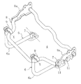
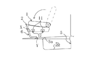
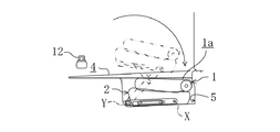
上記シートAは、図1に示すように、例えばバン型やワゴン型の自動車の3列目シートとして、車室内の2列目シートの後方に設けられていて、シートバック1とシートクッション2とを有している。該シートバック1の上端にはヘッドレスト3,3が着脱可能に取付けられる一方、下端は、左右両側に設けられた図示しないリクライニング機構によりシートクッション2の後端に前後に傾動可能に連結されている。
As shown in FIG. 1, the seat A is provided, for example, as a third-row seat of a van-type or wagon-type vehicle, behind the second-row seat in the passenger compartment. have.
上記シートAの後方の車体フロア4には、不使用時にシートAを収納するための略矩形状の収納凹部5が形成されており、シート不使用時には、図2に示すように、シートバック1がシートクション2側に折り畳まれた状態で収納されるようになっている。
The
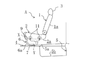
上記シートクッション2の前端の左右両側位置には、それぞれ略90度まで折れ曲がった略くの字形状のリンク部材6,6(図2には一方のみ示す)の先端部(シート側端部)が、車幅方向の回転軸Xの回りに回転自在に連結され、該一対のリンク部材6,6の基端部(車体側端部)は、上記収納凹部5の前方の車体フロア4上にブラケット7,7(図2には一方のみ示す)によりそれぞれ車幅方向の回転軸Yの回りに回転自在に連結されている。
At the left and right side positions of the front end of the
すなわち、上記一対のリンク部材6,6の先端部は、図3に示すように、シートクッション2のフレーム8に溶接された一対のブラケット9,9に、ボルトにより回転自在に連結され、一方基端部は、同様に車体フロア4に溶接されたブラケット7,7に、ボルトにより回転自在に連結されている。
That is, as shown in FIG. 3, the distal ends of the pair of
そして、図1のシート使用状態では、上記各リンク部材6の折曲部6aよりも基端側の部位が車体フロア4に当接する一方、折曲部6aよりも先端側の部位が車体フロア4から略垂直に上方に突出して、シートクッション2を支持するようになっている。なお、図1において、10,10は、それぞれ、リンク部材6,6とブラケット9,9との連結部位を覆うカバーである。
In the seat use state of FIG. 1, the base end side portion of each
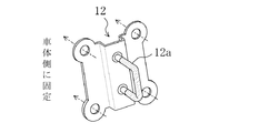
また、上記シートクッション2の左右両側面には、それぞれ前後2個のキャッチ11,11が配設されており、シート使用状態では、車体側に設けられたストライカ12,12(図4参照)と係合して上記シートクッション2に加わる荷重を支持するようになっている。すなわち、これらのキャッチ11,11は、図3に示すように、上記シートクッション2のフレーム8のサイドフレーム8a,8aにボルト止めされている。
In addition, two front and
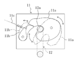
上記各キャッチ11は、例えば図5に示すように、開位置(同図に仮想線で示す)と閉位置(同図に実線で示す)との間で回転可能な略コの字形状の係合部材11aと、図示しないばねによりロック位置(同図に実線で示す)に付勢されたロック部材11bとを有し、該ロック部材11bをばねによる付勢力に抗してロック解除位置(同図に仮想線で示す)に引張するためのケーブル11cが接続されている。
For example, as shown in FIG. 5, each of the
そして、上記各キャッチ11及びストライカ12が上下方向から係合されるときには、まず、開位置の係合部材11aがストライカ12の上側ピン12aにより下方から押圧されて上方に回転し、ロック部材11bを上方に押上げて閉位置に位置付けられて、上記上側ピン12aを把持する。同時に、上記ロック部材11bがばねの付勢力によってロック位置に戻り、係合部材11aの下方への回転を阻止する。その際、ストライカ12の上側ピン12aの上縁は図示しないストッパラバーに当接して荷重を支持する状態になる。
When each of the
つまり、シート使用状態では、左右両側に2個づつ設けられた合計4個のキャッチ11,11,…が上下方向からストライカ12,12,…に係合されて、シートクッション2への荷重を支持するようになっている。
In other words, when the seat is in use, a total of four
一方、図2に示すシート収納状態では、一対のリンク部材6,6が回転軸Yの回りに略180度回転して、折曲部6a,6aの内周面が収納凹部5の開口前縁5aに当接するとともに、該折曲部6a,6aよりも先端側の部位が上記収納凹部5の内周に沿って下方に伸びるように位置付けられている。そして、シートクッション2は、上記リンク部材6,6によって前端部を吊下げられるとともに、底面2aが収納凹部5の底面5bに対向する状態で、即ちシート使用状態と略同じ姿勢で収納凹部5に収納されている。その際、上記シートクッション2の上方に略平行に折り畳まれたシートッバック1の裏面1aは車体フロア4と略面一になっている。
On the other hand, in the sheet storage state shown in FIG. 2, the pair of
なお、図2において、13はシートバック1のリクライニング機構を傾動不能のロック状態及び傾動可能のロック解除状態に切替えるためのダイヤルであり、14は、ケーブル11c引張して4個のキャッチ11,11,…のロック部材11b,11b,…を同時に開状態にさせるためのレバーである。
In FIG. 2,
次に、使用状態になっているシートAを収納凹部5に収納するときの動作を、図6〜図10に基づいて説明する。
Next, the operation when the sheet A in use is stored in the
まず、図6に示すように使用状態になっているシートAにおいて、左右のヘッドレスト3,3をシートバック1から脱き取り、ダイヤル13を操作してシートバック1をシートクッション2側へ(同図の反時計回り)略平行になるまで折り畳み(図7の状態)、この状態でリクライニング機構をロックする。続いて、レバー14を操作してキャッチ11,11を閉状態にしておいて、図8に示すように、シートクッション2を回転軸Xの回りに回転させて後部をやや上方に持ち上げ、各キャッチ11及びストライカ12の係合を外す。
First, in the seat A in use as shown in FIG. 6, the left and
そして、シートバック1及びシートクッション2を一体に後方へ引くことで、図9に示すように回転軸Yの回りに後回り(同図の時計回り)に収納凹部5内へ回転移動させる。このとき、シートクッション2を略水平に保持して移動させるようにすれば、該シートクッション2上の物を車体フロア4上に落とすことはない。
Then, by pulling back the seat back 1 and the
最後に、図10に示すように、シートバック1及びシートクッション2を、一体として回転軸Xの回りに下向きに回転させ、シートバック1の裏面1aが車体フロア4と略面一な状態として、シートの収納を終了する。この収納状態では、シートクッション2が下側に位置付けられてその底面2aが収納凹部5の底面5bに対向しているので、該収納凹部5の底にゴミや埃等が溜まっていても、それらがシートクッション2の底面2a以外の部分に付着することはなく、よって、シートAの使用感が損なわれることはない。
Finally, as shown in FIG. 10, the seat back 1 and the
なお、収納状態になっているシートAを収納凹部5から引出して使用状態にするときには、上記図6〜図10に示す動作を逆の順序で反対向きに行うようにすればよい。
When the sheet A in the storage state is pulled out from the
したがって、この参考例1では、シートクッション2をリンク部材6,6によって車体フロア4に連結したので、シートAを収納凹部5に収納可能としつつ該収納凹部5との位置関係を従来と比べて自由に決定することができる。つまり、シートのレイアウト上の制約を緩和することができる。また、シート収納状態では、リンク部材6,6が車体フロア4及び収納凹部5に沿って折れ曲がって配置されているので、スペース効率が向上する。
Therefore, in this reference example 1, since the
一方、シート使用状態においては、シートクッション2を前後左右の4箇所でキャッチ11,11,…及びストライカ12,12,…によって支持しているため、例えば非常に重い荷物をシートAに載せた場合でも、リンク部材6,6には荷重が加わることがない。このため、該リンク部材6,6の変形に起因するシート収納性の悪化を確実に防止することができる。
On the other hand, when the seat is in use, the
さらに、上記シートAを収納凹部5に収納するときに、図8に示すように、車体フロア4から略垂直に上方に突出しているリンク部材6,6によりシートクッション2を支持することができるので、収納動作が容易になる。また、上記リンク部材6,6が、左右(車幅方向)に互いに平行に設けられているので、シートAの回転移動時の安定性が向上する。加えて、該リンク部材6,6の先端部が、シートクッション2の前端に回転自在に連結されているので、シートバック1及びシートクッション2を後方に引くだけで、それほど大きな力を用いることなくかつ自然な動作で、シートAを収納凹部5に収納することができる。
Further, when the seat A is stored in the
(参考例2)
図11〜図13は、本発明の参考例2に係る車両用シートBを示す。
(Reference Example 2)
FIGS. 11-13 shows the vehicle seat B which concerns on the reference example 2 of this invention.
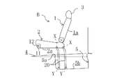
上記シートBは、上記参考例1に係るシートAと同様、不使用時には車体フロア4に形成された収納凹部5内に収納可能な構成としたものであるが、上記シートAとは、主にリンク部材の車体側取付け位置が異なっていて、シート収納時に、上記シートB及びリンク部材20,20が収納凹部5内に完全に収納されるようにしたものである。なお、上記シートBのその他の構成はシートAと同様なので、同一部材には同一符号を付してその説明は省略する。
The seat B is configured to be housed in a
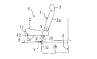
上記シートBでは、シートクッション2の左右両側にそれぞれ2本づつ、合計4本のリンク部材20,20,…(図には一方のみ示す)が連結されている。この各リンク部材20は略真直な棒状に形成され、先端部がシートクション2の後側の部位に車幅方向の回転軸Xの回りに回転自在に連結される一方、基端部が収納凹部5の底面5bに車幅方向の回転軸Yの回りに回転自在に連結されていて、上記シートクッション2を略水平状態に保ったまま回転移動させる平行リンク機構を構成している。すなわち、左右両側における2本づつのリンク部材20,20,…の内の一方が平行リンク構成部材となる。
In the seat B, a total of four
また、図11に示すシート使用状態では、シートクッション2の後側の部位が4本のリンク部材20,20,…により支持される一方、上記シートクッション2の前端左右両側に設けられたキャッチ11,11が、車体側に設けられたストライカ12,12と前後方向から係合して、上記シートクッション2の前側の部位を支持するようになっている。
11, the rear portion of the
そして、上記の使用状態になっているシートBを収納凹部5に収納するときの動作は、まず、シートAの場合と同様に左右のヘッドレスト3,3をシートバック1から脱きとり、ダイヤル13を操作してシートバック1をシートクッション2側へ(同図の反時計回り)略平行になるまで折り畳んで(図12の状態)、この状態でリクライニング機構をロックする。
When the seat B in the above-described use state is stored in the
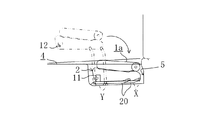
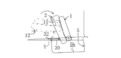
続いて、レバー14を操作してキャッチ11,11を解除し、図13に示すように、シートバック1及びシートクッション2を一体に後方へ引くと、各リンク部材20がそれぞれ回転軸Yの回りに回転して、上記シートバック1及びシートクッション2が収納凹部5内へ収納される。このように、シートバック1及びシートクッション2を一体として後方に移動させる簡単な動作で、容易にかつ短時間で収納できる。
Subsequently, the
このとき、シートクッション2はリンク部材20,20,…によって略水平に保持されつつ回転移動されるため、該シートクッション2の上に載せた物が車体フロアへ転落することを確実に防止することができる。すなわち、例えば薄手のクッション等を敷いたままシートBを収納凹部5に収納することができるので、使い勝手が大変良い。また、シートクッション2上に置き忘れた物があっても、その物の車体フロア4への転落による破損を確実に防止することができる。
At this time, since the
したがって、上記参考例2のシートBでは、参考例1のシートAと同様にシートのレイアウト上の制約を緩和することができる上、シート使用状態では、シートクッション2の後側の部位を略真直なリンク部材20,20,…によって支持するとともに、前側の部位をキャッチ11,11及びストライカ12,12に寄って支持することで、上記リンク部材20,20の変形を防止しつつ、シートBへの荷重を十分に支持することができる。
Therefore, in the seat B of the reference example 2, the restriction on the layout of the seat can be relaxed similarly to the seat A of the reference example 1, and the rear portion of the
また、リンク部材20,20の基端部が収納凹部5内に連結されていて、シート収納状態では、リンク部材20,20,…が完全に収納凹部5に収まるようになる。このため、シート収納状態では、車体フロア4上を突出物の全くない状態にすることができるので、荷物等を置くときの使い勝手が極めて良い。しかも、上記シートAと同様、ゴミや埃等の付着によって使用感が損なわれることがない。
Further, the base end portions of the
(参考例3)
図14〜図16は、本発明の参考例3としての車両用シートCを示す。すなわち、上記シートCでは、シートクッション2の後側の部位を左右一対のリンク部材22,22(図には一方のみ示す)により支持するとともに、該リンク部材22,22の回転に同期回転して、シートクッション2の傾きを制限する副リンク部材23,23を設けており、この副リンク部材23,23が、傾斜状態保持機構を構成している。なお、上記シートCのその他の構成は参考例1のシートAと同様なので、同一部材には同一符号を付してその説明は省略する。
(Reference Example 3)
14 to 16 show a vehicle seat C as Reference Example 3 of the present invention. That is, in the seat C, the rear portion of the
上記シートCでは、図14に示すように、シートクッション2の後側の部位の左右両側に一対のリンク部材22,22(図には一方のみ示す)の先端部が、車幅方向の回転軸Xの回りに回転可能に連結される一方、基端部は収納凹部5の底面5bに車幅方向の回転軸Yの回りに回転可能に連結されている。
In the seat C, as shown in FIG. 14, the distal ends of a pair of
また、シートクッション2の左右両側面には、シートクッション2の長手方向に延びるようにスライドガイド24,24が配設され、該スライドガイド24,24に対し、図示しないスライドピンにより副リンク部材23の先端部が摺動可能にかつ回転可能に連結されている。一方、上記各副リンク部材23の基端部は上記リンク部材22の先端部から3分の1程度の部位22aに回転可能に連結されている。このことで、上記各リンク部材22が回転軸Yの回りに回転して上記シートクッション2を回転移動させるとき、副リンク部材23が連結部位22aの回りに同期回転して、上記シートクッション2を略水平状態に保つようになっている。
Further, slide guides 24, 24 are provided on both the left and right side surfaces of the
また、図14に示すシート使用状態では、上述のシートBの場合と同様、シートクッション2の後側の部位がリンク部材22,22により支持される一方、上記シートクッション2の前端の左右両側位置に設けられた一対のキャッチ11,11が、車体側に設けられた左右一対のストライカ12,12と上下方向から係合することで、上記シートクッション2の前側の部位が支持されるようになっている。
In the seat use state shown in FIG. 14, as in the case of the seat B described above, the rear portion of the
そして、上記の使用状態になっているシートCを収納凹部5に収納するときの動作は、上述のシートBの場合と同様、シートバック1をシートクッション2側へ折り畳んでロックしておいて、(図15の状態)、それらを一体に後方へ引くだけでよく、これにより、シートクッション2を略水平に保持したままでシートCを収納凹部5へ収納することができる(図16の状態)。
And the operation | movement when accommodating the sheet | seat C in said use state in the accommodation recessed
したがって、上記シートCの場合、シートBと同様の作用効果を得ることができ、加えて、平行リンク機構と比べて、省スペース化及び軽量化が図られる。
(実施形態)
図17〜図19は、本発明の実施形態としての車両用シートDを示す。すなわち、上記シートDでは、シートクッション2の後側の部位を左右一対のリンク部材26,26によって支持する一方、前側の部位をキャッチ11,11(被支持部)及びストライカ12,12によって支持するようにしたものである。なお、上記シートDのその他の構成は参考例2、3のシートAと同様なので、同一部材には同一符号を付してその説明は省略する。
Therefore, in the case of the sheet C, it is possible to obtain the same effects as the sheet B, and in addition, space saving and weight reduction can be achieved as compared with the parallel link mechanism.
(Embodiment)
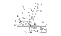
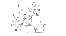
17 to 19 show a vehicle seat D as an embodiment of the present invention. That is, in the seat D, the rear portion of the
そして、図17に示すように使用状態になっているシートDを収納凹部5に収納するときの動作は、上述のシートB及びシートCの場合と略同様である。すなわち、シートバック1をシートクッション2側へ折り畳んでロックしておいて、(図18に仮想線で示す)、それらを一体に後方へ引き下ろすことで、回転軸Yの回りに回転移動させて上記収納凹部5に移動させ(図18の状態)、その後、シートバック1及びシートクッション2を一体として回転軸Xの回りに前回りに回転させて、上記収納凹部5へ収納する(図19の状態)。
Then, as shown in FIG. 17, the operation when the sheet D in use is stored in the
したがって、上記シートDの場合、シートを収納するときにシートクッション2が略水平に保持されないこと以外は、シートB及びCと略同様の作用効果を得ることができる。また、それらと比べて簡単な構成とすることができるので、低コスト化、省スペース化、軽量化等の利点がある。
(参考例4)
図20〜図23は、本発明の参考例4に係る車両用シートEを示す。
Therefore, in the case of the seat D, substantially the same operational effects as the seats B and C can be obtained except that the
(Reference Example 4)
20 to 23 show a vehicle seat E according to Reference Example 4 of the present invention.
上記シートEでは、左右一対のリンク部材30,30の先端部をシートクッション2の後側部位に回転自在に接続するとともに、該一対のリンク部材30,30の水平方向よりも下方への回転変位を制限するようにしている。なお、上記シートEのその他の構成は参考例1のシートAと同様なので、同一部材には同一符号を付してその説明は省略する。
In the seat E, the front ends of the pair of left and
上記一対のリンク部材30,30の先端部は、シートクッション2の底面2aにおける後側部位の左右両側位置に、ブラケット31,31により車幅方向の回転軸Xの回りに回転自在に連結されている。一方、基端部は、収納凹部5の開口前縁5aの左右両側にブラケット32,32により車幅方向の回転軸Yの回りに回転可能に連結されている。
The distal ends of the pair of
上記ブラケット32,32には、図21に示すように、それぞれ車体後方に略水平に伸びる突出部32a,32aが形成されていて、上記リンク部材30,30の先端部が基端部よりも低くなる水平方向よりも下方への回転変位を阻止するようになっている。この突出部32a,32aを有する一対のブラケット32,32が制限機構を構成している。
As shown in FIG. 21, the
また、図20に示すシート使用状態では、上記一対のリンク部材30,30によりシートクッション2の後側部位が支持される一方、該シートクッション2の前側部位の左右両側面にそれぞれ配設されたキャッチ11,11が、車体側に配設されたストライカ12,12と上下方向から係合して、上記シートクッション2の前側部位を支持するようになっている。
Further, in the seat usage state shown in FIG. 20, the rear portion of the
そして、上記の使用状態になっているシートEを収納凹部5に収納するときの動作は、まず、左右のヘッドレスト3,3をシートバック1から脱きとり、ダイヤル13を操作してシートバック1をシートクッション2側へ(同図の反時計回り)略平行になるまで折り畳んで(図22に仮想線で示す)、この状態でリクライニング機構をロックする。
When the seat E in the above-described use state is stored in the
続いて、レバー14を操作してキャッチ11,11を解除し、シートバック1及びシートクッション2を一体に後方へ引くと、左右一対のリンク部材30,30がそれぞれ回転軸Yの回りに後回りに回転して、上記シートバック1及びシートクッション2が後方に移動される。
Subsequently, the
そして、図22に示すように、各リンク部材30が、略水平状態でブラケット32,32の突出部32a,32aに当接してそれ以上の回転が阻止された状態で、上記シートバック1及びシートクッション2が収納凹部5の上方に位置付けられる。この状態から、図23に示すように、上記シートクッション2の前側部位をさらに後方に引き、該シートクッション2及びシートバック1を回転軸Xの回りに上下に反転させて、収納凹部5に収納する。
Then, as shown in FIG. 22, each
したがって、上記参考例4のシートEでは、参考例1のシートAと同様にシートのレイアウト上の制約を緩和することができる上、シート使用状態のシートEを収納凹部に収納するときには、シートバック1をシートクッション2側に折り畳んでおいて、それらをを一体に後方に引くだけの簡単な動作で、シートEをコンパクトな軌跡に沿って容易に収納することができる。
Therefore, the sheet E of the reference example 4 can ease the restrictions on the layout of the sheet similarly to the sheet A of the reference example 1, and when the sheet E in the sheet use state is stored in the storage recess, The seat E can be easily accommodated along a compact trajectory by a simple operation of folding 1 to the
その際、リンク部材30,30の回転変位が制限されていて、シートバック1及びシートクッション2が収納途中で収納凹部5に干渉しないような軌跡を辿るので、収納が一層容易になる。また、シート収納状態では、上記一対のリンク部材30,30は車体フロア4に沿って面一に配置されるので、荷物を置くときの妨げにはならない。
(参考例5)
図24及び図25は、本発明の参考例5に係る車両用シートFを示す。
At this time, the rotational displacement of the
(Reference Example 5)
24 and 25 show a vehicle seat F according to Reference Example 5 of the present invention.
上記シートFでは、左右一対のリンク部材40,40(図には一方のみ示す)の先端部をシートバック1にリジッド(相対変位不能)に連結する一方、上記一対のリンク部材40,40の基端部を収納凹部5よりも前方の車体フロア4上に回転自在に連結している。なお、上記シートFのその他の構成は参考例1のシートAと同様なので、同一部材には同一符号を付してその説明は省略する。
In the seat F, the front ends of a pair of left and
上記シートFでは、図24に示すように、シートバック1の裏面1aの下端の左右両側位置に、リンク部材40,40の先端部がリジッドに連結される一方、基端部は収納凹部5の前方の車体フロア4上に、ブラケット41,41によって車幅方向の回転軸Yの回りに回転自在に連結されていて、上記シートバック1及びシートクション2を一体に回転軸Yの回りに回転させることができるようにしている。
In the seat F, as shown in FIG. 24, the distal end portions of the
また、上記リンク部材40,40は、それぞれシート収納状態において車体フロア4及び収納凹部5の形状に沿って配置されるように、くの字形状に形成されている。
The
さらに、上記シートバック1の左右両側面には、それぞれ、位置固定用ピン42,42(図には一方のみ示す)が、図示しない切替レバーの操作に応じて上記両側面から出没可能に設けられ、該一対の位置固定用ピン42,42が車体側に設けられた図示しない位置固定用凹部に内嵌されることで、上記シートバック1の位置が固定されるようになっている。 Further, on the left and right side surfaces of the seat back 1, position fixing pins 42 and 42 (only one is shown in the figure) are provided so as to be able to protrude and retract from the both side surfaces in accordance with the operation of a switching lever (not shown). The position of the seat back 1 is fixed by fitting the pair of position fixing pins 42 and 42 into a position fixing recess (not shown) provided on the vehicle body side.
そして、図24に示すように使用状態になっているシートFを収納凹部5に収納するときの動作は、まず、シートクション2をシートバック1側に引き起こして折り畳んだ状態とし(図25に仮想線で示す)、続いて、位置固定用ピン42,42の位置固定用凹部との嵌合を解除してから、上記シートバック1及びシートクッション2を一体に回転軸Yの回りに後向きに回転移動させて、上記収納凹部5に収容する。
As shown in FIG. 24, when the seat F that is in use is stored in the
したがって、上記参考例5のシートFでは、参考例1のシートAと同様にシートのレイアウト上の制約を緩和することができる上、シート使用状態のシートEを収納凹部5に収納するときには、シートクッション2をシートバック1側に引き起こして、そのまま一体に後方に引き下ろす一連の動作で、容易にかつ短時間で収納することができる。
Therefore, in the sheet F of the reference example 5, as in the case of the sheet A of the reference example 1, restrictions on the sheet layout can be relaxed, and when the sheet E in the sheet use state is stored in the
また、リンク部材40,40の先端部がシートバック1にリジッドに連結されているので、この部分を回転可能に連結する場合に比べて、部品点数や摺動部分の削減によりコスト低減が図られる。
In addition, since the leading ends of the
さらに、シート収納状態では、リンク部材40,40が車体フロア4及び収納凹部5の形状にに沿って折れ曲がって配置されるので、スペース効率が向上する。
(参考例6)
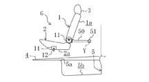
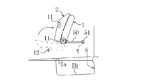
図26〜図28は、本発明の参考例6に係る車両用シートGを示す。
Furthermore, in the seat storage state, the
(Reference Example 6)
FIGS. 26-28 shows the vehicle seat G which concerns on the reference example 6 of this invention.
上記シートGは、左右一対のリンク部材50,50(図には一方のみ示す)の先端部をシートバック1にリジッド(相対変位不能)に連結する一方、基端部をシートGの後方の車体内壁に回転自在に連結している。なお、上記シートGのその他の構成は参考例1のシートAと同様なので、同一部材には同一符号を付してその説明は省略する。
The seat G is rigidly connected to the seat back 1 at the front ends of a pair of left and
上記シートGでは、図26に示すように、シートバック1の裏面1aの下端左右両側位置に、左右一対のリンク部材50,50の先端部がリジッドに連結される一方、基端部はシートGの後方の車体内壁に配設された回転ヒンジ51,51により、車幅方向の回転軸Yの回りに回転自在に連結されていて、上記シートバック1及びシートクション2を一体に上記回転軸Yの回りに回転移動させることができるようになっている。
In the seat G, as shown in FIG. 26, the distal ends of the pair of left and
また、上記シートクッション2の前端面は、収納の際に収納凹部5の開口前縁5aに干渉しないように、下側が徐々に後退する形状とされている。
Further, the front end surface of the
さらに、上記シートバック1の左右両側面には、それぞれ、キャッチ11,11(図には一方のみ示す)が設けられ、該キャッチ11,11が車体側に設けられた図示しないストライカと上下方向から係合することで、上記シートバック1が位置固定されるようになっている。
Further, catches 11 and 11 (only one is shown in the figure) are provided on the left and right side surfaces of the seat back 1, respectively, and the
そして、上記図26に示すように使用状態になっているシートGを収納凹部5に収納するときの動作は、まず、シートクション2をシートバック1側に引き起こして折り畳んだ状態でロックしておいて(図27の状態)、該シートバック1のキャッチ11,11を開状態にすれば、該シートバック1とシートクッション2とがそれらの自重により自然に回転軸Yの回りに前回りに回転移動して、上記収納凹部5に収容される(図28の状態)。
As shown in FIG. 26, when the seat G that is in use is stored in the
したがって、上記参考例6のシートGでは、参考例1のシートAと同様にシートのレイアウト上の制約を緩和することができる上、シート使用状態のシートGを収納凹部5に収納するときには、シートバック1及びシートクッション2がそれらの自重により、自然に前回りに回転移動して収納凹部5に収納されるので、シートの収納を極めて容易に行うことができる。
Therefore, in the sheet G of the reference example 6, as in the sheet A of the reference example 1, restrictions on the layout of the sheet can be relaxed, and when the sheet G in the sheet use state is stored in the
また、収納状態では、シートクッション2の底面2aが収納凹部5の底面5bに対向する状態になるので、該収納凹部5の底に溜まっているゴミや埃等の付着を防止することができ、シートの使用感が向上する。
(参考例7)
図29、図30及び図31は、本発明の参考例7に係る車両用シートHを示す。
In the storage state, the
(Reference Example 7)
29, 30 and 31 show a vehicle seat H according to Reference Example 7 of the present invention.
上記シートHは、左右一対のリンク部材60,60(図には一方のみ示す)の基端部をスライド機構61,61を介して車体側に連結したものである。なお、上記シートHのその他の構成は参考例1のシートAと同様なので、同一部材には同一符号を付してその説明は省略する。
The seat H is formed by connecting the base ends of a pair of left and
上記シートHでは、図29に示すように、左右一対のリンク部材60,60の先端部が、シートクッション2の前端の左右両側位置に車幅方向の回転軸Xの回りに回転自在に連結される一方、基端部は、前後方向に互いに平行に伸びる左右一対のスライドガイド62,62を介して、車体フロア4に連結されている。
In the seat H, as shown in FIG. 29, the front ends of the pair of left and
すなわち、上記各リンク部材60の基端部は、水平方向に突設されたスライドピン63により、スライドガイド62に摺動可能に、かつ回転自在に連結されている。
That is, the base end portion of each
そして、上記図29に示すように使用状態になっているシートHを収納凹部5に収納するときの動作は、まず、シートバック1をシートクッション2側へ折り畳んでロックし、それらをリンク部材60,60とともに回転軸Yの回りに後回りに略90度回転移動させるとともに、該リンク部材60,60に対して回転軸Xの回りに相対的に前回りに回転させて、略水平状態になったリンク部材60,60の上に上記シートバック1及びシートクッション2を立たせた状態で載置する(図30に仮想線で示す)。
As shown in FIG. 29, when the seat H that is in use is stored in the
続いて、図30に示すように、上記シートバック1及びシートクッション2を後方へスライド移動させて、スライドガイド62,62の後端部まで移動させ、最後に、回転軸Yの回りに後向きに回転移動させて収納凹部5に収納する(図31の状態)。
Subsequently, as shown in FIG. 30, the seat back 1 and the
したがって、上記参考例7のシートGでは、リンク部材60,60の基端部を、スライド機構により前後に移動可能にしたので、上述の各実施形態に係るシートA〜Fに比べても、使用状態におけるシートの配置を一層自由に決定することができ、シートのレイアウト上の制約をより一層緩和することができる。
Therefore, in the sheet G of the reference example 7, since the base end portions of the
しかも、まず、シートバック1及びシートクッション2を、リンク部材60,60の上に載置した上で、それらを一体に安定した状態でスライド移動させるようにしているので、比較的複雑な収納動作を十分に容易に行うことができる。
In addition, first, the seat back 1 and the
1 シートバック
2 シートクッション
2a シートクッションの裏面
4 車体フロア
5 収納凹部
5b 収納凹部の底面
26 リンク部材
11 キャッチ(被支持部)
12 ストライカ
D シート
Y 回転軸
DESCRIPTION OF
12 striker D sheet Y rotation axis
Claims (6)
上記シートは、車両前後方向における最後列のシートであり、
一端部が上記シートクッションの後側の部位に回転自在に連結される一方、他端部が上記収納凹部内にて車体側に回転自在に連結され、この車体側の連結位置の周りに回動されて上記シートを、上記使用状態と、上記収納凹部の底面にシートクッションの底面が対向する収納状態と、の間で移動させるリンク部材が設けられている
ことを特徴とする車両用シート構造。 In the vehicle seat structure in which the seat composed of the seat cushion and the seat back can be stored by moving it from the use state to a storage recess formed in the vehicle body floor behind the seat cushion.
The seat is the last row of seats in the vehicle longitudinal direction,
One end is rotatably connected to the rear portion of the seat cushion, while the other end is rotatably connected to the vehicle body side in the storage recess, and rotates around the connection position on the vehicle body side. A vehicle seat structure comprising a link member that moves the seat between the use state and a storage state in which the bottom surface of the seat cushion faces the bottom surface of the storage recess.
上記シートは、前後方向に3列のシートを有する車両の3列目のシートであり、
一端部が上記シートクッションの後側の部位に回転自在に連結される一方、他端部が上記収納凹部内にて車体側に回転自在に連結され、この車体側の連結位置の周りに回動されて上記シートを、上記使用状態と、上記収納凹部の底面にシートクッションの底面が対向する収納状態と、の間で移動させるリンク部材が設けられ、
上記リンク部材の一端部のシートクッションとの連結位置は、上記使用状態で他端部の車体側との連結位置の略真上に位置するように設定されている
ことを特徴とする車両用シート構造。 In a vehicle seat structure that can be stored by moving a seat composed of a seat cushion and a seat back from a use state in which the seat cushion is spaced above the vehicle body floor to a storage recess formed on the vehicle body floor behind the vehicle seat floor,
The seat is a third row seat of a vehicle having three rows of seats in the front-rear direction,
One end is rotatably connected to the rear portion of the seat cushion, while the other end is rotatably connected to the vehicle body side in the storage recess, and rotates around the connection position on the vehicle body side. A link member is provided for moving the seat between the use state and a storage state where the bottom surface of the seat cushion faces the bottom surface of the storage recess;
The vehicle seat, wherein the link position of the link member with the seat cushion at one end is set to be located substantially directly above the link position with the vehicle body at the other end in the use state. Construction.
少なくとも2本のリンク部材が、車幅方向に互いに平行に配設されていることを特徴とする車両用シート構造。 In either claim 1 or 2,
A vehicle seat structure, wherein at least two link members are arranged in parallel to each other in the vehicle width direction.
リンク部材の他端部は収納凹部の底面の前端部に連結されていることを特徴とする車両用シート構造。 In either claim 1 or 2,
A vehicle seat structure, wherein the other end of the link member is connected to the front end of the bottom surface of the storage recess.
シートクッションの前側の部位には、シート使用状態で車体側に支持される被支持部が設けられていることを特徴とする車両用シート構造。 In either claim 1 or 2,
A seat structure for a vehicle, characterized in that a supported portion that is supported on the vehicle body side when the seat is used is provided at a front portion of the seat cushion.
シート収納状態ではシートクッションの前端部がリンクの他端部に近接していることを特徴とする車両用シート構造。 In either claim 1 or 2,
A vehicle seat structure, wherein the front end portion of the seat cushion is close to the other end portion of the link when the seat is stored.
Priority Applications (1)
| Application Number | Priority Date | Filing Date | Title |
|---|---|---|---|
| JP2007204264A JP2007284060A (en) | 2007-08-06 | 2007-08-06 | Seat structure for vehicle |
Applications Claiming Priority (1)
| Application Number | Priority Date | Filing Date | Title |
|---|---|---|---|
| JP2007204264A JP2007284060A (en) | 2007-08-06 | 2007-08-06 | Seat structure for vehicle |
Related Parent Applications (1)
| Application Number | Title | Priority Date | Filing Date |
|---|---|---|---|
| JP20683197A Division JP4019456B2 (en) | 1997-07-31 | 1997-07-31 | Vehicle seat structure |
Related Child Applications (1)
| Application Number | Title | Priority Date | Filing Date |
|---|---|---|---|
| JP2008060942A Division JP2008150044A (en) | 2008-03-11 | 2008-03-11 | Vehicle seat structure |
Publications (2)
| Publication Number | Publication Date |
|---|---|
| JP2007284060A true JP2007284060A (en) | 2007-11-01 |
| JP2007284060A5 JP2007284060A5 (en) | 2008-04-24 |
Family
ID=38756204
Family Applications (1)
| Application Number | Title | Priority Date | Filing Date |
|---|---|---|---|
| JP2007204264A Pending JP2007284060A (en) | 2007-08-06 | 2007-08-06 | Seat structure for vehicle |
Country Status (1)
| Country | Link |
|---|---|
| JP (1) | JP2007284060A (en) |
Cited By (1)
| Publication number | Priority date | Publication date | Assignee | Title |
|---|---|---|---|---|
| CN113844346A (en) * | 2020-06-25 | 2021-12-28 | 三菱自动车工业株式会社 | Seat housing structure for vehicle |
-
2007
- 2007-08-06 JP JP2007204264A patent/JP2007284060A/en active Pending
Cited By (1)
| Publication number | Priority date | Publication date | Assignee | Title |
|---|---|---|---|---|
| CN113844346A (en) * | 2020-06-25 | 2021-12-28 | 三菱自动车工业株式会社 | Seat housing structure for vehicle |
Similar Documents
| Publication | Publication Date | Title |
|---|---|---|
| JP3990364B2 (en) | Folding seats and vehicles including such seats | |
| JP4434075B2 (en) | Vehicle seat moving device | |
| KR101081213B1 (en) | Fold and dive seat for vehicle | |
| JP2005335697A (en) | Vehicle seat, and vehicle provided with such seat | |
| JP5141680B2 (en) | Vehicle seat | |
| JP5252265B2 (en) | Leg cover structure of folding sheet | |
| JP4019456B2 (en) | Vehicle seat structure | |
| JP4785011B2 (en) | Vehicle seat | |
| JPH10297332A (en) | Seat for vehicle | |
| JP2008150044A (en) | Vehicle seat structure | |
| JP2007313977A (en) | Vehicle seat | |
| JP3992897B2 (en) | Underfloor storage seat structure | |
| JP2007284060A (en) | Seat structure for vehicle | |
| JP4281827B2 (en) | Vehicle seat structure | |
| JP2007284060A5 (en) | ||
| JP2010030594A (en) | Seat structure of vehicle | |
| JP2010030593A (en) | Seat structure of vehicle | |
| JP3977030B2 (en) | Seat cushion lock structure for flip-up type storage seat | |
| JP2002219978A (en) | Vehicle seat | |
| JP4489677B2 (en) | Seat back lock device for vehicle seat | |
| JP5857919B2 (en) | Lock mechanism | |
| JP2009107372A (en) | Ceiling storage type seat | |
| JP3719187B2 (en) | Vehicle seat | |
| JP4442460B2 (en) | Vehicle seat | |
| JP3806368B2 (en) | Vehicle seat |
Legal Events
| Date | Code | Title | Description |
|---|---|---|---|
| A621 | Written request for application examination |
Free format text: JAPANESE INTERMEDIATE CODE: A621 Effective date: 20070806 |
|
| A521 | Written amendment |
Effective date: 20080311 Free format text: JAPANESE INTERMEDIATE CODE: A523 |
|
| A871 | Explanation of circumstances concerning accelerated examination |
Free format text: JAPANESE INTERMEDIATE CODE: A871 Effective date: 20080311 |
|
| A975 | Report on accelerated examination |
Free format text: JAPANESE INTERMEDIATE CODE: A971005 Effective date: 20080409 |
|
| A131 | Notification of reasons for refusal |
Free format text: JAPANESE INTERMEDIATE CODE: A131 Effective date: 20080422 |
|
| A521 | Written amendment |
Effective date: 20080623 Free format text: JAPANESE INTERMEDIATE CODE: A523 |
|
| A131 | Notification of reasons for refusal |
Effective date: 20080819 Free format text: JAPANESE INTERMEDIATE CODE: A131 |
|
| A521 | Written amendment |
Free format text: JAPANESE INTERMEDIATE CODE: A523 Effective date: 20081020 |
|
| A131 | Notification of reasons for refusal |
Free format text: JAPANESE INTERMEDIATE CODE: A131 Effective date: 20081118 |
|
| A521 | Written amendment |
Effective date: 20090119 Free format text: JAPANESE INTERMEDIATE CODE: A523 |
|
| A02 | Decision of refusal |
Free format text: JAPANESE INTERMEDIATE CODE: A02 Effective date: 20090310 |
|
| A521 | Written amendment |
Effective date: 20090507 Free format text: JAPANESE INTERMEDIATE CODE: A523 |
|
| A911 | Transfer of reconsideration by examiner before appeal (zenchi) |
Free format text: JAPANESE INTERMEDIATE CODE: A911 Effective date: 20090525 |
|
| A912 | Removal of reconsideration by examiner before appeal (zenchi) |
Effective date: 20090703 Free format text: JAPANESE INTERMEDIATE CODE: A912 |