JP4489677B2 - Seat back lock device for vehicle seat - Google Patents
Seat back lock device for vehicle seat Download PDFInfo
- Publication number
- JP4489677B2 JP4489677B2 JP2005284182A JP2005284182A JP4489677B2 JP 4489677 B2 JP4489677 B2 JP 4489677B2 JP 2005284182 A JP2005284182 A JP 2005284182A JP 2005284182 A JP2005284182 A JP 2005284182A JP 4489677 B2 JP4489677 B2 JP 4489677B2
- Authority
- JP
- Japan
- Prior art keywords
- seat
- sheet
- state
- seat back
- striker
- Prior art date
- Legal status (The legal status is an assumption and is not a legal conclusion. Google has not performed a legal analysis and makes no representation as to the accuracy of the status listed.)
- Active
Links
Images


Description
本発明は、車両用シートのシートバックロック装置に関する。詳しくは、車幅方向に並べて配設された複数のシートのうち一のシートのシートバックには、このシートに隣接する他のシートのシートバックに突出して設けられた被係合部に係合ロックして受け止められる係合部が設けられており、係合部と被係合部との係合ロックにより一のシートのシートバックの傾き角度位置を他のシートのシートバックと同じ傾き角度位置に保持することのできる車両用シートのシートバックロック装置に関する。 The present invention relates to a seat back lock device for a vehicle seat. Specifically, the seat back of one of the plurality of seats arranged side by side in the vehicle width direction is engaged with an engaged portion that protrudes from the seat back of another seat adjacent to the seat. An engaging portion that is locked and received is provided, and the inclination angle position of the seat back of one seat is the same as the seat back of the other seat by the engagement lock between the engaging portion and the engaged portion. The present invention relates to a seat back lock device for a vehicle seat that can be held on the vehicle.
従来、車両のリヤシートには、シートバックの傾き角度を調整するためのリクライニング機構を持たない、いわゆるフリーヒンジタイプのシート(以下、フリーシート)が配設されていることがある。このフリーシートは、シートバックがシートクッションに対して傾動可能には構成されているが、このシート単体の構成だけではシートバックを一定の傾き角度位置に止めておくことのできない構成となっている。そこで、このフリーシートのシートバックを、リクライニング機構を備えた隣接するシートのシートバックや車体側壁に係合させて凭れ掛けさせることにより、一定の傾き角度位置に保持できるようにした技術が提案されている。
この種の関連技術として、特許文献1や特許文献2に開示された技術を挙げることができる。これらの開示技術では、フリーシートのシートバック側部にロック装置が備え付けられており、車体側壁にはこのロック装置に係合ロック可能となるストライカがシートバック側に突出した状態として設けられている。この構成によれば、シートバックを車両後方側に向けて傾倒させることにより、ロック装置を車体側壁から突出したストライカに係合ロックさせることができ、このロック位置にてシートバックの傾き角度を保持しておくことができる。
また、同開示技術では、シートバックを一定の傾き角度位置に保持する必要のない時、例えばシートバックをシートクッション側に倒し込んで折畳状態としたり、シート自体を車両前方にスライド移動させたりする時には、これらの動作に連動させて、車体側壁から突出しているストライカを折り畳んで格納することのできる構成となっている。これにより、上記不要時には、ストライカによる出張りをなくして邪魔にならない状態とすることができる。
Conventionally, a rear seat of a vehicle may be provided with a so-called free hinge type seat (hereinafter referred to as a free seat) that does not have a reclining mechanism for adjusting a tilt angle of a seat back. The free seat is configured such that the seat back can tilt with respect to the seat cushion, but the seat back cannot be stopped at a certain tilt angle position only by the configuration of the seat alone. . Therefore, a technique has been proposed in which the seat back of this free seat can be held at a constant tilt angle position by engaging with the seat back of an adjacent seat provided with a reclining mechanism or the side wall of the vehicle body and leaning. ing.
As this type of related technique, the techniques disclosed in Patent Document 1 and Patent Document 2 can be cited. In these disclosed technologies, a lock device is provided on the seat back side portion of the free seat, and a striker that can be engaged and locked with the lock device is provided on the side wall of the vehicle body so as to protrude to the seat back side. . According to this configuration, by tilting the seat back toward the rear side of the vehicle, the lock device can be engaged and locked with the striker protruding from the side wall of the vehicle body, and the tilt angle of the seat back is maintained at this lock position. Can be kept.
Further, in the disclosed technique, when it is not necessary to hold the seat back at a certain tilt angle position, for example, the seat back is folded down to the seat cushion side, or the seat itself is slid forward in the vehicle. When doing so, the striker protruding from the side wall of the vehicle body can be folded and stored in conjunction with these operations. Thereby, when it is not necessary, it is possible to eliminate the protrusion by the striker so as not to get in the way.
しかしながら、上記従来の技術では、フリーシートを隣接するシートのシートバックに係合ロックさせる構成として適用した場合、このフリーシートに更にシート収納機構等の付加機能を持たせると、かかる一連の動作に不具合を生じさせることがあった。
例えば、折畳姿勢状態としたフリーシートを隣接するシート側に横跳ね上げ可能とするシート収納機構を構成した場合には、フリーシートを折畳姿勢とする動作に連動させてストライカを格納状態とすることができるため、横跳ね上げしたフリーシートとストライカとが干渉することを回避することができる。しかし、このシート収納機構を備えた構成にあって、更にフリーシートとこれに隣接するシートとを折畳姿勢状態として車両前方に一斉に跳ね上げ可能とするシートタンブル機構を構成しようとすると、フリーシートを折畳姿勢とした段階でストライカが格納状態とされてしまうため、両シートが係合されず、これらを一斉に跳ね上げることができなくなる。
However, in the above-described conventional technique, when the free sheet is applied as a configuration in which the free sheet is engaged and locked to the seat back of the adjacent sheet, if the free sheet is further provided with an additional function such as a sheet storage mechanism, such a series of operations is performed. It sometimes caused problems.
For example, when a sheet storage mechanism is configured that allows a free sheet in a folded position to be flipped up to the adjacent sheet, the striker is stored in conjunction with the operation of setting the free sheet in a folded position. Therefore, it is possible to avoid interference between the free-seat raised up and the striker. However, if the seat tumble mechanism is provided with this seat storage mechanism, and a free seat and a seat adjacent to the seat storage mechanism are folded in a folded posture, the seat tumble mechanism can be lifted all at once. Since the striker is placed in the retracted state when the sheets are in the folded posture, both the sheets are not engaged and cannot be flipped up at the same time.
本発明は、上記した問題を解決するものとして創案されたものであって、本発明が解決しようとする課題は、フリーシートのシートバックを隣接するシートのシートバックに係合ロックさせる構成において、このフリーシートに更にシート収納機構やシートタンブル機構等の付加機能を持たせても、かかる一連の動作を不具合なく行えるようにすることにある。 The present invention was devised as a solution to the above-described problem, and the problem to be solved by the present invention is a configuration in which a seat back of a free sheet is engaged and locked with a seat back of an adjacent sheet. Even if this free sheet is further provided with additional functions such as a sheet storage mechanism and a sheet tumble mechanism, the series of operations can be performed without any trouble.
上記課題を解決するために、本発明の車両用シートのシートバックロック装置は次の手段をとる。
先ず、第1の発明は、車幅方向に並べて配設された複数のシートのうち一のシートのシートバックには、シートに隣接する他のシートのシートバックに突出して設けられた被係合部に係合ロックして受け止められる係合部が設けられており、係合部と被係合部との係合ロックにより一のシートのシートバックの傾き角度位置を他のシートのシートバックと同じ傾き角度位置に保持することのできる車両用シートのシートバックロック装置であって、一のシートのシートバックをシートクッション側に倒し込んだ折畳状態でこのシートを隣接する他のシート側に横跳ね上げさせて収納状態とすることのできるシート収納機構と、シート収納機構の動作に連動可能に設けられ、被係合部を係合部と係合ロック可能に突出させた突出状態と係合ロック不能にシートバック内に格納させた格納状態とに切換えることのできるロック状態切換機構と、を有し、ロック状態切換機構は、シート収納機構により折畳状態の一のシートを横跳ね上げさせる動作に連動して被係合部を格納状態とし、一のシートの姿勢状態がシートバックを傾動させた際の係合部の移動軌跡に被係合部が突出状態であれば係合ロック可能となる関係位置にある状態時には被係合部を突出状態とするものである。
この第1の発明によれば、被係合部は、折畳状態とした一のシートを他のシート側に横跳ね上げする時には格納状態となる。したがって、跳ね上げ収納される一のシートと被係合部とが干渉することが回避される。また、被係合部は、一のシートの姿勢状態が係合部と突出状態の被係合部とが係合ロック可能となる関係位置にある状態時には突出状態となる。したがって、例えば、折畳状態とした一のシートに対し他のシートを折畳状態とすることで、両シートのシートバックを相互に係合ロックさせることができる。
In order to solve the above problems, the seat back lock device for a vehicle seat of the present invention takes the following means.
First, the first invention is an engaged state in which a seat back of one of a plurality of seats arranged side by side in the vehicle width direction is provided to protrude from a seat back of another seat adjacent to the seat. An engagement portion that is received by being locked to the engagement portion is provided, and the inclination angle position of the seat back of one sheet is changed from the seat back of another sheet by the engagement lock between the engagement portion and the engaged portion. A seat back lock device for a vehicle seat that can be held at the same inclination angle position, and in a folded state in which the seat back of one seat is folded down to the seat cushion side, this seat is placed on the other adjacent seat side. A sheet storage mechanism that can be raised to the side and brought into a storage state, and a protrusion state that is provided so as to be interlocked with the operation of the sheet storage mechanism and that the engaged portion protrudes from the engagement portion so as to be engaged and lockable. Together A lock state switching mechanism that can be switched to a stored state that is impossiblely stored in the seat back, and the lock state switching mechanism is an operation that causes one seat in the folded state to be flipped up sideways by the seat storage mechanism. The engaged portion is set in the retracted state in conjunction with the movement of the engagement portion, and the engagement lock is possible if the engaged portion protrudes from the movement locus of the engaging portion when the posture state of one seat tilts the seat back. The engaged portion is set to the protruding state when the state is in the related position.
According to the first aspect, the engaged portion is in the retracted state when the one sheet in the folded state is flipped up to the other sheet side. Accordingly, it is possible to avoid interference between the one sheet to be flipped up and stored and the engaged portion. Further, the engaged portion is in the protruding state when the posture state of one sheet is in a relational position where the engaging portion and the engaged portion in the protruding state can be locked. Therefore, for example, the seat backs of both the sheets can be engaged and locked with each other by setting the other sheets to the folded state with respect to the one sheet in the folded state.
次に、第2の発明は、上述した第1の発明において、被係合部は、一のシートのシートバックに向けて突出して設けられたストライカであり、ロック状態切換機構は、ストライカを起倒回動可能に連結するヒンジ機構部と、ストライカと一のシートの横跳ね上げ動作に伴って変位する部位とに連結され、常時はストライカを突出状態に維持し、一のシートの横跳ね上げ動作により引張操作されてストライカを回動させ格納状態とする操作ケーブルを含んで構成される操作機構部と、を有するものである。
この第2の発明によれば、ストライカに連結された操作ケーブルは、一のシートが横跳ね上げされる動作によって引張操作される。これにより、突出状態とされていたストライカは、回動して格納状態となる。
Next, in a second aspect based on the first aspect described above, the engaged portion is a striker provided so as to protrude toward the seat back of one seat, and the lock state switching mechanism starts the striker. It is connected to the hinge mechanism part that is connected so as to be able to turn over and the part that is displaced in accordance with the striker and the one-side-up movement of the one sheet. And an operation mechanism unit including an operation cable that is pulled by the operation to rotate the striker and put it in a retracted state.
According to the second aspect of the invention, the operation cable connected to the striker is pulled by an operation in which one sheet is flipped up sideways. Thereby, the striker made into the protrusion state rotates and it will be in a retracted state.
次に、第3の発明は、上述した第2の発明において、シート収納機構は、一のシートを横跳ね上げ可能に連結する跳上機構部と、跳上機構部に連動可能に設けられ、一のシートを横跳ね上げさせる動作に連動して跳ね上げ収納される一のシートを他のシートに対して車幅方向に離間移動させて一のシートの跳ね上げ回動を許容する空間を確保するべく他のシートから車幅方向に離間移動する移動機構部と、を有し、操作機構部の操作ケーブルは、移動機構部によって他のシートから車幅方向に離間移動する部位に連結されているものである。
この第3の発明によれば、操作ケーブルは、一のシートが横跳ね上げされる動作に伴って他のシートから車幅方向に離間する方向へ移動する部位に引張り込まれて引張操作される。
Next, according to a third aspect, in the second aspect described above, the sheet storage mechanism is provided so as to be interlocked with a jumping mechanism unit that connects one sheet so that it can be flipped up sideways, The space for allowing one sheet to be flipped up is secured by moving the one sheet, which is flipped up and stored in conjunction with the operation of causing one sheet to be flipped up sideways, away from the other seats in the vehicle width direction. And a moving mechanism portion that moves away from other seats in the vehicle width direction, and the operation cable of the operation mechanism portion is connected to a portion that moves away from the other seats in the vehicle width direction by the moving mechanism portion. It is what.
According to the third aspect of the invention, the operation cable is pulled and pulled into a portion that moves in a direction away from the other seat in the vehicle width direction as one seat is flipped up sideways. .
次に、第4の発明は、上述した第3の発明において、シート収納機構は、車両フロア或いは他のシートと一体に設けられた節が固定節となり一のシートと一体に設けられた節が固定節の対向節となって構成される四節リンク機構から成り、四節リンク機構における他のシート側に配置されたコネクタ節が一のシートの跳ね上げ回動方向とは反対の回動方向に回動して他のシートから車幅方向に離間移動する移動機構部を構成しているものである。
この第4の発明によれば、シート収納機構を構成する跳上機構部及び移動機構部が、一のシートと車両フロア或いは他のシートとを連結する四節リンク機構によりこれに含まれて構成される。そして、操作ケーブルは、この四節リンク機構を構成するコネクタ節に連結されて引張操作される。
Next, according to a fourth aspect of the present invention, in the third aspect described above, the seat storage mechanism includes a node provided integrally with the vehicle floor or another seat, and a node provided integrally with the one seat. It consists of a four-joint link mechanism that is configured as an opposite joint of a fixed joint, and the connector joint arranged on the other sheet side in the four-joint link mechanism is the direction of rotation opposite to the direction in which one sheet jumps And a moving mechanism that moves away from other seats in the vehicle width direction.
According to the fourth aspect of the present invention, the jumping mechanism portion and the moving mechanism portion constituting the seat storage mechanism are included in the four-bar linkage mechanism that connects one seat and the vehicle floor or another seat. Is done. The operation cable is connected to the connector node constituting the four-bar linkage mechanism and is pulled.
次に、第5の発明は、上述した第2から第4のいずれかの発明において、ストライカの格納状態は、ストライカが他のシートのシートバック外形形状の内部に収容された回動位置状態として設定されているものである。
この第5の発明によれば、シートバックから突出して設けられるストライカは、シートバック外形形状の内部に収められる位置まで回動させることにより、格納状態となる。したがって、操作ケーブルに必要とされる引張り込み長さは、ストライカを格納状態位置まで回動させることのできる程度で足る。
Next, according to a fifth aspect of the present invention, in any one of the second to fourth aspects, the striker is stored in a rotational position state in which the striker is housed inside the seatback outer shape of another seat. It is set.
According to the fifth aspect of the invention, the striker that is provided so as to protrude from the seat back is brought into a retracted state by being rotated to a position where it is housed in the outer shape of the seat back. Therefore, the pull-in length required for the operation cable is sufficient to allow the striker to be rotated to the retracted position.
本発明は上述した手段をとることにより、次の効果を得ることができる。
先ず、第1の発明によれば、一のシート(フリーシート)を隣接する他のシートのシートバックに係合ロックさせる構成において、この一のシートに更にシート収納機構やシートタンブル機構等の付加機能を持たせても、かかる一連の動作を不具合なく行うことができる。
更に、第2の発明によれば、第1の発明の構成を、比較的簡単な構造によって具現化することができる。
更に、第3の発明によれば、固定設置された他のシートから離間移動する構成を備えることにより、操作ケーブルを引張操作するための引張変位量を確保し易くなる。
更に、第4の発明によれば、シート収納機構及びロック状態切換機構の構成を、より簡単な構造によって具現化することができる。
更に、第5の発明によれば、ストライカを格納状態とするために必要な操作ケーブルの引張り込み長さが短くて済むため、ストライカを突出状態と格納状態とに切換え易くなる。
The present invention can obtain the following effects by taking the above-described means.
First, according to the first invention, in the configuration in which one sheet (free sheet) is engaged and locked with the seat back of another adjacent sheet, a sheet storage mechanism, a sheet tumble mechanism, and the like are further added to the one sheet. Even if the function is provided, such a series of operations can be performed without any trouble.
Furthermore, according to the second invention, the configuration of the first invention can be realized by a relatively simple structure.
Furthermore, according to the third aspect of the present invention, it is easy to ensure a tensile displacement amount for pulling the operation cable by providing a structure that moves away from another fixedly installed sheet.
Furthermore, according to the fourth aspect, the configurations of the sheet storage mechanism and the lock state switching mechanism can be realized with a simpler structure.
Furthermore, according to the fifth aspect, since the pulling length of the operation cable necessary for putting the striker into the retracted state is short, the striker can be easily switched between the protruding state and the retracted state.
以下に、本発明を実施するための最良の形態の実施例について、図面を用いて説明する。 Embodiments of the best mode for carrying out the present invention will be described below with reference to the drawings.
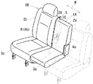
始めに、実施例1の車両用シートのシートバックロック装置について、図1〜図9を用いて説明する。図1は車両用シートの概略構成を表した斜視図、図2はフリーシート1Aの横跳ね上げ収納動作を表した斜視図、図3はフリーシート1A及びリクライニングシート1Bの折畳動作を表した斜視図、図4はフリーシート1A及びリクライニングシート1Bのタンブル収納動作を表した側面図、図5はストライカ20のロック状態が切換えられる動作を表した斜視図、図6はストライカ20の連結構造を表した側面図、図7はロック機構10のロック状態が切換えられる動作を表した側面図、図8はロック機構10を解除状態に切換えた状態を表した側面図、図9は収納機構30の動作を表した側面図である。
First, the seat back lock device for a vehicle seat according to the first embodiment will be described with reference to FIGS. FIG. 1 is a perspective view showing a schematic configuration of a vehicle seat, FIG. 2 is a perspective view showing a side flip-up storing operation of the
本実施例の車両用シートは、図1に良く示されるように、車両のリヤシートとして適用されている。このリヤシートは、車幅方向Wに並べて配設された3つのシートのうち中央のシートは、シートバック2aの傾き角度を調整するためのリクライニング機構を持たない、いわゆるフリーヒンジタイプのシート(以下、フリーシート1A)となっている。このフリーシート1Aは、シートバック2aがシートクッション3aに対して傾動可能には構成されているが、このシート単体の構成だけではシートバック2aを一定の傾き角度位置に止めておくことのできない構成となっている。しかし、このフリーシート1Aのシートバック2aは、同図の紙面内奥方に隣接するリクライニング機構Rを備えたリクライニングシート(以下、リクラシートと称する)1Bのシートバック2bに係合ロック可能に構成されている。したがって、同係合ロックにより、フリーシート1Aのシートバック2aを、リクラシート1Bのシートバック2bと同じ傾き角度位置に保持することができる。ここで、フリーシート1Aが本発明の一のシートに相当し、リクラシート1Bが本発明の他のシートに相当する。
これらフリーシート1A及びリクラシート1Bは、リヤシート全体の着座面や背もたれ面が車幅方向Wに略連続的に構成されるように、両者の外形形状の間にほとんど隙間が形成されないように寄せられて配設されている。また、フリーシート1A及びリクラシート1Bは、同軸上の位置に設定された各傾動軸4a,4bによって、それぞれ軸回りに傾動可能に構成されている。
The vehicle seat of the present embodiment is applied as a rear seat of a vehicle as well shown in FIG. This rear seat is a so-called free hinge type seat (hereinafter, referred to as “free hinge type seat”) that does not have a reclining mechanism for adjusting the inclination angle of the seat back 2a, among the three seats arranged side by side in the vehicle width direction W.
The
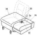
また、フリーシート1Aは、図2に良く示されるように、その着座使用をしない不要時には、上記リクラシート1Bとの係合ロックを解除し、シートバック2aをシートクッション3a側に折り畳んだ状態(図2の仮想線状態)で、リクラシート1B側に横跳ね上げさせて収納状態(図2の実線状態)とすることができる。このフリーシート1Aの収納動作は、そのシートクッション3a下部とリクラシート1Bのシートクッション3b下部との間に設けられたシート収納機構(以下、収納機構と称する)30の動作に伴って行われる。そして、このようにフリーシート1Aを横跳ね上げさせた収納状態とすることにより、その空けられた空間をウォークスルー用の空間や荷室空間として活用することが可能となる。
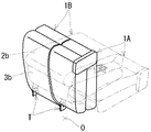
一方、リクラシート1Bは、上記の如く設けられた収納機構30によって、フリーシート1Aを車両フロアOに対して支持している。このリクラシート1Bは、図4に良く示されるように、その着座使用をしない不要時には、シートバック2bをシートクッション3b側に折り畳んだ状態で、車両前方に跳ね上げさせて収納状態とすることができる。このリクラシート1Bの収納動作は、シートクッション3bの前端下部と車両フロアOとの間に設けられたタンブル機構Tの動作に伴って行われる。本実施例では、このリクラシート1Bの収納動作時に、フリーシート1Aをリクラシート1Bと係合ロックさせた状態(図1参照)、或いはフリーシート1Aを収納せずに折り畳んだ状態(図3参照)としておくことにより、図4に良く示されるように、フリーシート1Aも一緒にタンブル収納することのできる構成となっている。そして、このようにフリーシート1Aとリクラシート1Bとを合わせてタンブル収納することにより、その空けられた空間を荷室空間として広く活用することができる。
Further, as shown in FIG. 2, the
On the other hand, the
ところで、上記フリーシート1Aのシートバック2aとリクラシート1Bのシートバック2bとの係合ロックは、図1に良く示されるように、フリーシート1Aのシートバック2aに設けられたフック状のロック機構10が、リクラシート1Bのシートバック2bにおいて突出して設けられた門型形状のストライカ20に係合ロックして受け止められることにより行われている。ここで、ロック機構10が本発明の係合部に相当する。
By the way, the engagement lock between the seat back 2a of the
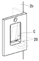
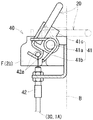
ここで、ストライカ20は、シートバック2bにおけるフリーシート1Aと隣接する側面に設けられており、常時はフリーシート1Aのシートバック2a側に向けて車幅方向Wに突出する状態(図5の仮想線状態)として設けられている。このストライカ20は、図2を参照して分かるように、ロック機構10により係合ロック使用されない不要時、具体的には前述したフリーシート1Aの横跳ね上げ収納動作時には、シートバック2bの外形形状の内部に収容した格納状態(図5の破線状態)とすることができる。このストライカ20の格納状態では、図6の実線で示されるように、ストライカ20はシートバック2bの外形形状を成す外形側面Bよりも内側に位置している。ここで、図5に良く示されるように、シートバック2bには、格納状態とされたストライカ20を外部に対して被覆することのできる窓掛けCが垂れ掛けられている。この窓掛けCは、可撓性を有した薄板状のゴム材によって形成されており、ストライカ20を突出させる際には内側から押し出される形で撓み変形し、ストライカ20の格納展開動作を阻害しない構成となっている。また、ストライカ20の格納動作は、図6に良く示されるように、ストライカ20をシートバック2bの骨格を成すバックフレームFに対して起倒回動可能に連結するロック状態切換機構(以下、切換機構と称する)40の動作に伴って行われる。
この切換機構40は、図2に良く示されるように、前述した収納機構30の動作に連動可能に設けられており、フリーシート1Aを横跳ね上げさせる収納動作に連動してストライカ20を回動させ格納状態(図2の破線状態)とする。これにより、ストライカ20の突出による出張りをなくすることができ、跳ね上げ収納されるフリーシート1Aとストライカ20とが干渉することを回避することができる。また、切換機構40は、上記跳ね上げ収納状態(図2の実線状態)のフリーシート1Aを跳ね上げ収納前の折畳状態(図2の仮想線状態)に戻し返す展開動作に連動して、ストライカ20を戻し返す方向に展開回動させ、前述した突出状態(図2の仮想線状態)とする。
このように、切換機構40は、収納機構30による収納動作や展開動作に連動してストライカ20を格納状態と突出状態とに切換えることができるが、その他の動作によっては連動せず、ストライカ20の位置状態(ロック状態)を切換えることなく維持することができる。したがって、フリーシート1Aの姿勢状態が図1や図3に示されるようにシートバック2aを傾動させた際のロック機構10の移動軌跡にストライカ20が突出状態であれば係合ロック可能となる関係位置にある状態時には、常に、ストライカ20は突出状態として維持される。すなわち、上記の関係位置にある状態時とは、図3の仮想線状態を参照して分かるように、例えば折畳状態とされたフリーシート1Aのシートバック2aを車両後方側に向けて傾倒させることにより、ストライカ20が突出状態であればロック機構10とストライカ20とを係合ロックさせることのできる状態時のことである。或いは、図3の実線状態を参照して分かるように、フリーシート1Aの折畳状態で、リクラシート1Bのシートバック2bを車両前方側に向けて傾倒させることにより、ロック機構10とストライカ20とを係合ロックさせることのできる状態時のことでもある。
Here, the
As shown in FIG. 2, the
As described above, the
以下、各構成部材について、詳細に説明する。
先ず、ロック機構10は、図3に良く示されるように、フリーシート1Aのシートバック2aにおけるリクラシート1Bと隣接する側面に設けられており、シートバック2aの外形形状の内部に収容されて、その側面と背裏面とから外部に露呈した構成となっている。具体的には、図7に良く示されるように、ストライカ20に係合ロック可能に形成されたフック部材11が、回動軸11aによって、シートバック2aの骨格を成すバックフレームFに一体に取付けられた支承部13に対して回動可能に取付けられている。このフック部材11は、同図の仮想線で示されるように、ロック機構10をストライカ20に向けて押込み操作することにより、その顎形状に形成された当接部位11bがストライカ20に当接して押動され、同図で示す反時計回り方向に回動する。これにより、フック部材11は、同図の実線で示されるように、その顎形状に窪んで形成された開口部位11cがストライカ20に下方から掬い掛けられて掛着する。この掛着状態では、フック部材11の回動端部に形成された係止部位11dが、同じく支承部13に対して回動軸12b回りに回動可能に連結された爪部材12の爪部位12aと当接して係止するようになっているため、ロック機構10がストライカ20に係合ロックした状態として保持される。また、支承部13は、ロック機構10の内部に押し込まれるストライカ20のストッパとして機能する。
このロック機構10の係合ロック状態は、図1に示されるシートバック2aの肩口位置に設けられた解除ストラップSの引張操作を行うことによって解除状態に切換えることができる。すなわち、図7に良く示されるように、解除ストラップSの引張操作を行うと、これに連結された爪部材12が同図の実線で示された位置状態から時計回り方向に回動操作される。これにより、図8に良く示されるように、爪部材12とフック部材11との係止状態を外すことができる。そして、この両者の間に連結されたバネ部材14の附勢作用によって、フック部材11を解除方向(時計回り方向)に附勢回動させることができるため、ストライカ20を開口部位11cから押し外して、ロック機構10とストライカ20との係合ロック状態を解除することができる。
なお、解除ストラップSの引張操作を止めた状態では、フック部材11は、図7の仮想線で示されるロック可能状態とされるため、再度、ロック機構10をストライカ20に向けて押込み操作することにより、係合ロックさせることができる。
Hereinafter, each component will be described in detail.
First, as well shown in FIG. 3, the
The engagement lock state of the
Note that, when the pulling operation of the release strap S is stopped, the
次に、切換機構40は、図6に良く示されるように、門型形状を成すストライカ20をバックフレームFに対して起倒回動可能に連結するヒンジ機構部41と、ストライカ20の根元側部位に連結されて前述した収納機構30による収納動作や展開動作に連動してストライカ20を回動操作する操作機構部42と、を有する。
前者のヒンジ機構部41は、ストライカ20と一体に接合された連結部材41cが回動軸41aに対して回動可能に取付けられている。これにより、ストライカ20が、同図で示す実線位置と仮想線位置との間で回動軸41a回りに回動可能とされている。このヒンジ機構部41の回動軸41aには、ストライカ20を同図で示す時計回り方向に回動附勢するバネ部材41b(スパイラルスプリング)が設けられている。これにより、ストライカ20は、自由状態では突出状態となるように附勢されている。
後者の操作機構部42は、ストライカ20と収納機構30との間に連結された操作ケーブル42aを有する。詳しくは、操作ケーブル42aは、その一端がストライカ20の根元側部位に連結されており、他端が後述する収納機構30(図9参照)の第1コネクタ節33に連結されている。この第1コネクタ節33は、フリーシート1Aを収納する収納動作時には、時計回り方向に回動し、操作ケーブル42aを引張り込むように作用する。ここで、操作ケーブル42aは、図6に良く示されるように、上記引張操作される前の自由状態時には、ストライカ20を引張り込むことなく、突出状態の位置にて保持している(図6の仮想線状態)。そして、操作ケーブル42aは、収納機構30の収納動作に伴って引張操作されることにより、ストライカ20を引張り込むように作用する。これにより、ストライカ20を、バネ部材41bによる回動附勢に抗して反時計回り方向に回動させ、格納状態とする(図6の実線状態)。このストライカ20の格納状態は、操作ケーブル42aが引張操作されている間は維持される。
Next, as well shown in FIG. 6, the
In the
The latter
次に、収納機構30は、図9に良く示されるように、リクラシート1Bと一体に設けられた固定節31と、この固定節31に対向配置されてフリーシート1Aと一体に設けられた対向節32と、を第1コネクタ節33及び第2コネクタ節34によってそれぞれリンク連結した四節リンク機構として構成されている。ここで、第1コネクタ節33が本発明のコネクタ節に相当する。これら各節は、紙面奥方に向けて長尺となる板形状に形成されており、同リンク連結した四節リンク機構によりフリーシート1Aをリクラシート1Bに対して片持ち支持可能な支持強度が持たされている。
上記四節リンク機構より成る収納機構30は、フリーシート1Aを横跳ね上げさせるべく、これと一体を成す対向節32を図9の仮想線で示される展開位置から反時計回り方向に起立回動させると、リクラシート1Bの側に配設された第1コネクタ節33が時計回り方向に沈み込むように回動する。これにより、対向節32を、リクラシート1Bから離間移動させながら反時計回り方向に回動させる。そして、これにより、対向節32が回動して起立姿勢となるフリーシート1Aの収容状態(図9の実線状態)時には、このフリーシート1Aとリクラシート1Bとの間に、車幅方向W(紙面内左右方向)の一定の収納空間Aを形成することができる。この収納空間Aにより、折畳状態とされてシート厚の大きくなったフリーシート1Aの跳ね上げ回動を許容することができ、フリーシート1Aを収納状態とするために必要な車幅方向Wの収納空間Aを確保することができる。すなわち、この四節リンク機構によって、フリーシート1Aを横跳ね上げ可能に連結する跳上機構部と、フリーシート1Aをリクラシート1Bに対して車幅方向Wに離間移動させる移動機構部と、が構成されている。ここで、第1コネクタ節33は、対向する第2コネクタ節34に向けて湾曲した曲板形状に形成されている。これにより、対向節32が起立姿勢となるフリーシート1Aの収納状態(図9の実線状態)時には、第1コネクタ節33を固定節31や第2コネクタ節34と重合させる状態位置に収めることができ、上記収納されて起立姿勢となるフリーシート1Aの高さ方向(紙面内上下方向)の収納空間Aを広く確保することができる。
また、第1コネクタ節33には、フック形状のブラケット33aが一体に設けられており、このブラケット33aに対して前述した操作ケーブル42aの他端が連結されている。この操作ケーブル42aは、第1コネクタ節33が図9の仮想線で示される展開位置、すなわちフリーシート1Aが収納される前の状態位置では、引張操作されずに自由状態とされている。そして、操作ケーブル42aは、フリーシート1Aの収納動作に伴って第1コネクタ節33が時計回り方向に回動することにより、この第1コネクタ節33に引張り込まれる(図9の実線状態)。これにより、操作ケーブル42aは、前述したように、ストライカ20(図6参照)を引張り込んで格納状態に切換える。
Next, as shown in FIG. 9, the
The
The
続いて、本実施例の使用方法を説明する。
始めに、図1に良く示されるように、着座可能な姿勢状態としてシートバック2aがリクラシート1Bのシートバック2bに係合ロックされた状態のフリーシート1Aを、リクラシート1B側に横跳ね上げして収納状態とする方法を説明する。この状態では、フリーシート1Aのシートバック2aに設けられたロック機構10とリクラシート1Bのシートバック2bに設けられたストライカ20とが係合ロックした状態となっている。そこで、先ず、フリーシート1Aの肩口位置に設けられた解除ストラップSの引張り操作を行う。これにより、フリーシート1Aのシートバック2aとリクラシート1Bのシートバック2bとの係合ロック状態が解除される。したがって、フリーシート1Aのシートバック2aをシートクッション3a側に前倒しすることにより、フリーシート1Aを折畳状態(図2の仮想線状態)とすることができる。このフリーシート1Aの折畳状態では、ストライカ20は突出状態として維持されている。次いで、折畳状態のフリーシート1Aをリクラシート1B側に向けて横跳ね上げする。これにより、フリーシート1Aの横跳ね上げ動作に連動して、ストライカ20がシートバック2bの外形形状内部に格納される。したがって、横跳ね上げしたフリーシート1Aを、ストライカ20と干渉させることなく、収納状態(図2の実線状態)とすることができる。ここで、収納状態とされたフリーシート1Aを横跳ね上げする前の状態(図2の仮想線状態)に戻し返す展開動作を行うと、ストライカ20は、再び突出状態となる。したがって、図2の仮想線状態に展開させたフリーシート1Aのシートバック2aを車両後方側に向けて傾倒させることにより、図1に良く示されるように、リクラシート1Bのシートバック2bと係合ロックさせることができる。
次に、リクラシート1Bをフリーシート1Aと共に車両前方に跳ね上げて収納状態とする方法を説明する。すなわち、図1に良く示されるように、前述したようにフリーシート1Aのシートバック2aとリクラシート1Bのシートバック2bとが係合ロックされた状態では、リクラシート1Bのシートバック2bをシートクッション3b側に前倒しして折畳状態とすることにより、合わせてフリーシート1Aも折畳状態(図4の仮想線状態)となる。或いは、図3に良く示されるように、前述したようにフリーシート1Aのシートバック2aをリクラシート1Bのシートバック2bとの係合ロック状態から解除して前倒しした折畳状態では、リクラシート1Bのシートバック2bを前倒しして折畳状態(図3の実線状態)とすることにより、ストライカ20をロック機構10に係合ロックさせることができる。したがって、図4に良く示されるように、これらフリーシート1Aのシートバック2aとリクラシート1Bのシートバック2aとが係合ロックした折畳状態で、フリーシート1A或いはリクラシート1Bを車両前方に跳ね上げることにより、両者を一斉にタンブルさせて収納状態とすることができる。
Subsequently, a method of using the present embodiment will be described.
First, as shown well in FIG. 1, the
Next, a method for raising the
このように、本実施例の車両用シートのシートバックロック装置によれば、フリーシート1Aのシートバック2aを隣接するリクラシート1Bのシートバック2bに係合ロックさせる構成において、フリーシート1Aを横跳ね上げして収納することのできる収納機構30や、リクラシート1Bと共に車両前方へ跳ね上げて収納するためのタンブル機構Tを組合わせて構成しても、かかる一連の動作を不具合なく行うことができる。そして、このような構成を、操作ケーブル42aにより引張操作を行う切換機構40を収納機構30に連動させた、比較的簡単な構成によって実現することができる。更に、フリーシート1Aを好適に横跳ね上げ収納可能とする収納機構30を、四節リンク機構として簡単に構成することができる。更に、操作ケーブル42aを、回動変位量の大きい四節リンク機構の第1コネクタ節33と連結することで、フリーシート1Aの収納・展開動作に連動させて、ストライカ20の格納・展開動作を良好に行うことができる。
Thus, according to the seat back lock device for a vehicle seat of this embodiment, the
以上、本発明の実施形態を1つの実施例により説明したが、本発明は上記実施例のほか各種の形態で実施ができるものである。
例えば、リクラシートをフリーシートと共に移動させて収納する形態は、これらを車両前方向にタンブルさせるものに限定されず、車両の使用形態に合わせて、後方向にタンブルさせるものや、車両前後方向に沈み込ませて格納状態とするもの等、種々の形態を採用することができる。また、フリーシートをリクラシートと共に移動させて収納する構成をとらない場合には、収納機構をフリーシートとリクラシートとの間にではなく、車両フロアとの間に配設してもよい。
また、ストライカを突出状態と格納状態とに切換える機構は、ストライカを起倒回動させる構成に限定されず、例えば操作ケーブルの操作状態に合わせてストライカを往復直線運動させてシートバックに対して出没動させる構成等、種々の構成を適用することができる。
また、収納機構は、収納機構部と移動機構部とを兼ね備えて機能する四節リンク機構としたものを示したが、例えばヒンジ機構等の収納機構部に相当する構成と、スライダ機構等の移動機構部に相当する構成と、を別個独立して設けた構成としてもよい。
Although the embodiment of the present invention has been described with one example, the present invention can be implemented in various forms in addition to the above example.
For example, the manner in which the lycra seat is moved together with the free seat and stored is not limited to the one that tumbles in the front direction of the vehicle. Various forms such as a storage state by being inserted can be adopted. Further, when the free seat is not moved and stored together with the lycra seat, the storage mechanism may be disposed not between the free seat and the lycra seat but between the vehicle floor.
Further, the mechanism for switching the striker between the protruding state and the retracted state is not limited to the configuration in which the striker is turned upside down. For example, the striker moves back and forth linearly according to the operation state of the operation cable. Various configurations such as a configuration to be moved can be applied.
In addition, the storage mechanism is shown as a four-bar linkage mechanism that functions as both a storage mechanism part and a movement mechanism part. However, the structure corresponding to the storage mechanism part such as a hinge mechanism and the movement of the slider mechanism, etc. It is good also as a structure which provided the structure corresponded to a mechanism part separately independently.
1A フリーシート(一のシート)
1B リクライニングシート(他のシート)
2a,2b シートバック
3a,3b シートクッション
4a,4b 傾動軸
10 ロック機構(係合部)
11 フック部材
11a 回動軸
11b 当接部位
11c 開口部位
11d 係止部位
12 爪部材
12a 爪部位
12b 回動軸
13 支承部
14 バネ部材
20 ストライカ
30 シート収納機構
31 固定節
32 対向節
33 第1コネクタ節(コネクタ節)
33a ブラケット
34 第2コネクタ節
40 ロック状態切換機構
41 ヒンジ機構部
41a 回動軸
41b バネ部材
41c 連結部材
42 操作機構部
42a 操作ケーブル
C 窓掛け
R リクライニング機構
T タンブル機構
W 車幅方向
S 解除ストラップ
F バックフレーム
A 収納空間
O 車両フロア
B 外形側面
1A Free sheet (one sheet)
1B Reclining seat (other seats)
2a, 2b Seat back 3a,
DESCRIPTION OF
Claims (5)
前記一のシートを該シートのシートバックをシートクッション側に倒し込んだ折畳状態で前記隣接する他のシート側に横跳ね上げさせて収納状態とすることのできるシート収納機構と、
該シート収納機構の動作に連動可能に設けられ、前記被係合部を前記係合部と係合ロック可能に突出させた突出状態と係合ロック不能にシートバック内に格納させた格納状態とに切換えることのできるロック状態切換機構と、
を有し、
該ロック状態切換機構は、前記シート収納機構により前記折畳状態の一のシートを横跳ね上げさせる動作に連動して前記被係合部を格納状態とし、前記一のシートの姿勢状態がシートバックを傾動させた際の係合部の移動軌跡に前記被係合部が突出状態であれば係合ロック可能となる関係位置にある状態時には該被係合部を突出状態とすることを特徴とする車両用シートのシートバックロック装置。 The seat back of one of the plurality of seats arranged side by side in the vehicle width direction is engaged and locked with an engaged portion that protrudes from the seat back of another seat adjacent to the seat. An engagement portion that is received is provided, and the inclination angle position of the seat back of the one sheet is set to the same inclination angle position as the seat back of the other sheet by the engagement lock between the engagement portion and the engaged portion. A vehicle seat back lock device that can be held,
A seat storage mechanism capable of causing the one seat to be stored in a folded state in which the seat back of the seat is folded down to the seat cushion side and then flipped sideways to the other adjacent seat side;
A protruding state in which the engaged portion is provided so as to be interlocked with the operation of the seat storage mechanism, and protruded so as to be engageable with the engaging portion; A lock state switching mechanism that can be switched to,
Have
The lock state switching mechanism sets the engaged portion in a retracted state in conjunction with an operation of causing the sheet storage mechanism to flip up one sheet in the folded state, and the posture state of the one sheet is a seat back. If the engaged portion is in a projecting state on the movement locus of the engaging portion when tilted, the engaged portion is in a projecting state when in a related position where the engagement can be locked. A seat back lock device for a vehicle seat.
前記被係合部は、前記一のシートのシートバックに向けて突出して設けられたストライカであり、
前記ロック状態切換機構は、前記ストライカを起倒回動可能に連結するヒンジ機構部と、前記ストライカと前記一のシートの横跳ね上げ動作に伴って変位する部位とに連結され、常時は前記ストライカを前記突出状態に維持し、前記一のシートの横跳ね上げ動作により引張操作されて前記ストライカを回動させ前記格納状態とする操作ケーブルを含んで構成される操作機構部と、を有することを特徴とする車両用シートのシートバックロック装置。 The vehicle seat backlock device according to claim 1,
The engaged portion is a striker provided to protrude toward the seat back of the one sheet,
The lock state switching mechanism is connected to a hinge mechanism portion for connecting the striker so that the striker can be rotated up and down, and a portion that is displaced in accordance with a lateral jumping operation of the striker and the one seat. And an operation mechanism portion configured to include an operation cable that is pulled by a lateral flip-up operation of the one sheet to rotate the striker to enter the retracted state. A seat back lock device for a vehicle seat.
前記シート収納機構は、前記一のシートを横跳ね上げ可能に連結する跳上機構部と、該跳上機構部に連動可能に設けられ、前記一のシートを横跳ね上げさせる動作に連動して該跳ね上げ収納される一のシートを前記他のシートに対して車幅方向に離間移動させて該一のシートの跳ね上げ回動を許容する空間を確保するべく前記他のシートから車幅方向に離間移動する移動機構部と、を有し、
前記操作機構部の操作ケーブルは、前記移動機構部によって前記他のシートから車幅方向に離間移動する部位に連結されていることを特徴とする車両用シートのシートバックロック装置。 A seat back lock device for a vehicle seat according to claim 2,
The sheet storage mechanism is provided so as to be capable of interlocking with the jumping mechanism unit that couples the one sheet so that the sheet can be flipped up side by side, and in conjunction with the operation of causing the one sheet to be flipped up sideways. In order to secure a space for allowing the one seat to be flipped up and stored to move away from the other seat in the vehicle width direction to allow the one seat to be flipped up in the vehicle width direction. And a moving mechanism part that moves away from
The seat back lock device for a vehicle seat, wherein the operation cable of the operation mechanism unit is connected to a portion that moves away from the other seat in the vehicle width direction by the moving mechanism unit.
前記シート収納機構は、車両フロア或いは前記他のシートと一体に設けられた節が固定節となり前記一のシートと一体に設けられた節が前記固定節の対向節となって構成される四節リンク機構から成り、該四節リンク機構における前記他のシート側に配置されたコネクタ節が前記一のシートの跳ね上げ回動方向とは反対の回動方向に回動して前記他のシートから車幅方向に離間移動する移動機構部を構成していることを特徴とする車両用シートのシートバックロック装置。 A vehicle seat back lock device according to claim 3,
In the seat storage mechanism, a node provided integrally with a vehicle floor or the other seat is a fixed node, and a node provided integrally with the one seat is an opposite node of the fixed node. A connector mechanism disposed on the other sheet side of the four-bar link mechanism is rotated in a rotation direction opposite to the flip-up rotation direction of the one sheet, and is separated from the other sheet. A seat back lock device for a vehicle seat, comprising a moving mechanism that moves away in the vehicle width direction.
前記ストライカの格納状態は、該ストライカが前記他のシートのシートバック外形形状の内部に収容された回動位置状態として設定されていることを特徴とする車両用シートのシートバックロック装置。
A seat back lock device for a vehicle seat according to claim 2,
The seat back lock device for a vehicle seat, wherein the stowed state of the striker is set as a rotational position state in which the striker is housed inside a seat back outer shape of the other seat.
Priority Applications (1)
| Application Number | Priority Date | Filing Date | Title |
|---|---|---|---|
| JP2005284182A JP4489677B2 (en) | 2005-09-29 | 2005-09-29 | Seat back lock device for vehicle seat |
Applications Claiming Priority (1)
| Application Number | Priority Date | Filing Date | Title |
|---|---|---|---|
| JP2005284182A JP4489677B2 (en) | 2005-09-29 | 2005-09-29 | Seat back lock device for vehicle seat |
Publications (2)
| Publication Number | Publication Date |
|---|---|
| JP2007091077A JP2007091077A (en) | 2007-04-12 |
| JP4489677B2 true JP4489677B2 (en) | 2010-06-23 |
Family
ID=37977287
Family Applications (1)
| Application Number | Title | Priority Date | Filing Date |
|---|---|---|---|
| JP2005284182A Active JP4489677B2 (en) | 2005-09-29 | 2005-09-29 | Seat back lock device for vehicle seat |
Country Status (1)
| Country | Link |
|---|---|
| JP (1) | JP4489677B2 (en) |
Families Citing this family (1)
| Publication number | Priority date | Publication date | Assignee | Title |
|---|---|---|---|---|
| DE202021104964U1 (en) | 2020-09-15 | 2021-12-02 | Pi̇lot Taşit Koltuklari Sanayi̇ Ve Ti̇caret Anoni̇m Şi̇rketi̇ | Gear mechanism assembly for vehicle seats |
-
2005
- 2005-09-29 JP JP2005284182A patent/JP4489677B2/en active Active
Also Published As
| Publication number | Publication date |
|---|---|
| JP2007091077A (en) | 2007-04-12 |
Similar Documents
| Publication | Publication Date | Title |
|---|---|---|
| JP4105534B2 (en) | Vehicle seat | |
| JP4190553B2 (en) | Vehicle seat device | |
| JP5252265B2 (en) | Leg cover structure of folding sheet | |
| JP2005502519A (en) | Car seat | |
| WO2007043586A1 (en) | Seat structure, seat extension/retraction method, and vehicle | |
| JP6450934B2 (en) | Vehicle seat | |
| JPH10297332A (en) | Seat for vehicle | |
| JP4019456B2 (en) | Vehicle seat structure | |
| JP2008150044A (en) | Vehicle seat structure | |
| JP4489677B2 (en) | Seat back lock device for vehicle seat | |
| JP5251112B2 (en) | Vehicle seat | |
| JP3992897B2 (en) | Underfloor storage seat structure | |
| JP2019064307A (en) | Vehicle seat | |
| JP6432446B2 (en) | Vehicle seat | |
| JP6387836B2 (en) | Vehicle seat | |
| JP4970142B2 (en) | Unlocking mechanism for vehicle seat | |
| JP3982006B2 (en) | Full flat foldable seat | |
| JP2001030812A (en) | Folding seat for vehicle | |
| JP4281827B2 (en) | Vehicle seat structure | |
| JP4480679B2 (en) | Vehicle seat | |
| JP4468315B2 (en) | Vehicle seat | |
| JP2009107372A (en) | Ceiling storage type seat | |
| JP2007284060A (en) | Seat structure for vehicle | |
| JP2001030814A (en) | Folding rear seat | |
| JP5223104B2 (en) | Ceiling retractable seat |
Legal Events
| Date | Code | Title | Description |
|---|---|---|---|
| A621 | Written request for application examination |
Free format text: JAPANESE INTERMEDIATE CODE: A621 Effective date: 20080110 |
|
| A977 | Report on retrieval |
Free format text: JAPANESE INTERMEDIATE CODE: A971007 Effective date: 20100303 |
|
| TRDD | Decision of grant or rejection written | ||
| A01 | Written decision to grant a patent or to grant a registration (utility model) |
Free format text: JAPANESE INTERMEDIATE CODE: A01 Effective date: 20100309 |
|
| A01 | Written decision to grant a patent or to grant a registration (utility model) |
Free format text: JAPANESE INTERMEDIATE CODE: A01 |
|
| A61 | First payment of annual fees (during grant procedure) |
Free format text: JAPANESE INTERMEDIATE CODE: A61 Effective date: 20100331 |
|
| FPAY | Renewal fee payment (event date is renewal date of database) |
Free format text: PAYMENT UNTIL: 20130409 Year of fee payment: 3 |
|
| R150 | Certificate of patent or registration of utility model |
Ref document number: 4489677 Country of ref document: JP Free format text: JAPANESE INTERMEDIATE CODE: R150 Free format text: JAPANESE INTERMEDIATE CODE: R150 |
|
| FPAY | Renewal fee payment (event date is renewal date of database) |
Free format text: PAYMENT UNTIL: 20130409 Year of fee payment: 3 |
|
| FPAY | Renewal fee payment (event date is renewal date of database) |
Free format text: PAYMENT UNTIL: 20140409 Year of fee payment: 4 |
|
| R250 | Receipt of annual fees |
Free format text: JAPANESE INTERMEDIATE CODE: R250 |
|
| R250 | Receipt of annual fees |
Free format text: JAPANESE INTERMEDIATE CODE: R250 |
|
| R250 | Receipt of annual fees |
Free format text: JAPANESE INTERMEDIATE CODE: R250 |
|
| R250 | Receipt of annual fees |
Free format text: JAPANESE INTERMEDIATE CODE: R250 |
|
| R250 | Receipt of annual fees |
Free format text: JAPANESE INTERMEDIATE CODE: R250 |
|
| R250 | Receipt of annual fees |
Free format text: JAPANESE INTERMEDIATE CODE: R250 |
|
| R250 | Receipt of annual fees |
Free format text: JAPANESE INTERMEDIATE CODE: R250 |
|
| R250 | Receipt of annual fees |
Free format text: JAPANESE INTERMEDIATE CODE: R250 |