JP2005297788A - Seat device for vehicle - Google Patents
Seat device for vehicle Download PDFInfo
- Publication number
- JP2005297788A JP2005297788A JP2004117441A JP2004117441A JP2005297788A JP 2005297788 A JP2005297788 A JP 2005297788A JP 2004117441 A JP2004117441 A JP 2004117441A JP 2004117441 A JP2004117441 A JP 2004117441A JP 2005297788 A JP2005297788 A JP 2005297788A
- Authority
- JP
- Japan
- Prior art keywords
- seat
- vehicle
- seats
- width direction
- vehicle width
- Prior art date
- Legal status (The legal status is an assumption and is not a legal conclusion. Google has not performed a legal analysis and makes no representation as to the accuracy of the status listed.)
- Pending
Links
- JOYRKODLDBILNP-UHFFFAOYSA-N Ethyl urethane Chemical compound CCOC(N)=O JOYRKODLDBILNP-UHFFFAOYSA-N 0.000 description 2
- 238000000926 separation method Methods 0.000 description 2
- 239000004744 fabric Substances 0.000 description 1
- 239000002828 fuel tank Substances 0.000 description 1
- 238000005192 partition Methods 0.000 description 1
- 238000004804 winding Methods 0.000 description 1
Images


Landscapes
- Seats For Vehicles (AREA)
Abstract
Description
この発明は、左右のシート間の車幅方向の幅を変更可能に構成したような車両用シート装置に関する。 The present invention relates to a vehicle seat device configured such that the width in the vehicle width direction between left and right seats can be changed.
一般に車両の左右のリヤシートを後方に移動させて、フロントシートとリヤシートとの間を荷室に設定したり、後席乗員の快適性を向上させることが要請されるが、リヤシートの後方には車幅方向内方に車室側へ突出する一対のホイールハウスが設けられているため、リヤシートをそのまま後方に移動させることはできない。 In general, it is required to move the left and right rear seats of the vehicle rearward to set the space between the front seat and the rear seat as a luggage compartment, and to improve the comfort of the rear seat passengers. Since a pair of wheel houses projecting inward in the width direction are provided, the rear seat cannot be moved rearward as it is.
このような問題点を解決するため従来から各種のシート装置が発明されている。
特許文献1に記載の車両用リヤシートは、左シートと右シートとの間にセンターシートを配設し、左右のシートをホイールハウス間に移動させる場合、センターシートを前方に移動させ、次に左シートおよび右シートを斜め後方に近接させながら移動して、これら左右のシートを一対のホイールハウス間に配設するように構成したものである。
In order to solve such problems, various sheet devices have been invented.
In the rear seat for a vehicle described in
この従来装置においてはフロントシートの後方に、前方へ移動させたセンタシートが位置することになり、このセンタシートが邪魔になるばかりでなく、該センタシートを車両の前後方向に移動案内させる専用のレールが別途必要となり、構造が複雑化する問題点があった。 In this conventional apparatus, a center seat moved forward is located behind the front seat, and this center seat is not only in the way, but also dedicated to moving and guiding the center seat in the longitudinal direction of the vehicle. There was a problem that a separate rail was required and the structure was complicated.
特許文献2に記載のスライドシートは、左シートと右シートとの間に、シートクッション部とシートバック部とを有する折り畳み式のサブシートを設け、左右のシートをホイールハウス間に移動させる場合、折り畳み式のサブシートのシートバック部をシートクッション部上に折り畳んだ後に、この折り畳み式のサブシートの全体を左シートまたは右シート側に折り畳み、次に左シートおよび右シートを斜め後方に近接させながら移動して、これら左右のシートを一対のホイールハウス間に配設するように構成したものである。
When the slide seat described in
この従来装置においては、折り畳み式のサブシートのシートバック部の前後方向の肉厚と、シートクッション部の上下方向の肉厚との合計肉厚分により左右のシートの近接量が制限される問題点があった。 In this conventional apparatus, there is a problem in that the proximity amount of the left and right seats is limited by the total thickness of the seat back portion in the front-rear direction and the thickness in the up-down direction of the seat cushion portion of the folding sub-seat There was a point.
特許文献3に記載の車両用シート装置は、リヤフロア上に車両の前後方向に延び、かつ左右シート間を広くする前側のストレート部と、車両の前後方向に延び、かつ左右シート間を狭くする後側のストレート部と、これら前後の各ストレート部を傾斜状に連設するスラント部とから成る平面視略Z字状の左右対称のスライドレールを設け、これらスライドレールに沿って左右のシートを移動させるように構成し、左右のシートをホイールハウス間に移動させる場合には、これら各シートを後側のストレート部に移動させて、左右のシートを一対のホイールハウス間に配設するように構成したものである。
The vehicle seat device described in
この従来装置においては、左右のシートをホイールハウス間に移動させた時には、左右のシートの近接によりベンチシート態様となるが、左右のシートを前方に移動させると、左右のシート間が大きく離間して、ベンチシート態様が不可能となる。つまり前後の両移動位置においてベンチシート態様を確保することが不可能となるうえ、上述の如き形状のスライドレールが必要となり、構造が複雑化する問題点があった。
そこで、この発明は、車幅方向に複数に分割されて並設した座席を設け、これら各座席をそれぞれが車体に対して車幅方向に移動可能に支持する一方、座席の間を接続し、かつ座席間に収納可能なシート状態のサブシート部材を設けて、座席の車幅方向の寸法が変更可能に構成することにより、シートの前後の方向のスペースに影響を与えることなく、シート幅を可変とすることができ、シートの移動とスペースの有効活用との両立を図ることができるうえ、構造のシンプル化を達成することができる車両用シート装置の提供を目的とする。 Therefore, the present invention provides a plurality of seats divided in the vehicle width direction and juxtaposed, and supports each of these seats so as to be movable in the vehicle width direction with respect to the vehicle body, while connecting the seats, In addition, by providing a sub-seat member in the seat state that can be stored between the seats, and by configuring the seat to be changeable in the vehicle width direction, the seat width can be increased without affecting the space in the front-rear direction of the seat. An object of the present invention is to provide a vehicle seat device that can be made variable, can achieve both the movement of the seat and the effective use of the space, and can achieve the simplification of the structure.
この発明による車両用シート装置は、車幅方向に複数に分割されて並設した座席を有する車両用シート装置であって、上記座席はそれぞれが車体に対して車幅方向に移動可能に支持される一方、上記座席の間を接続し、かつ座席間に収納可能なシート状態のサブシート部材を設け、上記座席の車幅方向の寸法が変更可能に構成されたものである。 The vehicle seat device according to the present invention is a vehicle seat device having a plurality of seats arranged in parallel in the vehicle width direction, and each of the seats is supported so as to be movable in the vehicle width direction with respect to the vehicle body. On the other hand, a sub-seat member in a seat state that connects between the seats and can be stored between the seats is provided, and the dimensions of the seats in the vehicle width direction can be changed.
上述のシート状のサブシート部材は、網目織りされた布やネット状の部材などの弾力性を有するものが望ましい。
上記構成によれば、上述のシート状のサブシート部材で座席間を接続したので、それぞれの座席の近接または離間により座席の車幅方向の寸法を容易に変更することができ、また座席の近接時には上記シート状のサブシート部材は座席間に収納される。
The sheet-like sub-sheet member described above preferably has elasticity such as a mesh-woven cloth or a net-like member.
According to the above configuration, since the seats are connected by the above-described sheet-like sub-seat members, the dimensions in the vehicle width direction of the seats can be easily changed by the proximity or separation of the respective seats, and the proximity of the seats Sometimes the sheet-like sub-seat member is housed between seats.
この結果、シートの前後方向のスペースに影響を与えることなく、シート幅を可変とすることができ、シートの移動とスペースの有効活用との両立を図ることができるうえ、構造のシンプル化を達成することができる。
この発明の一実施態様においては、上記座席のそれぞれはシートクッションとシートバックを備え、上記シートクッション同士が上記サブシート部材にて接続されたものである。
As a result, the seat width can be made variable without affecting the front-rear space of the seat, and it is possible to achieve both the movement of the seat and the effective use of the space, and the simplification of the structure. can do.
In one embodiment of the present invention, each of the seats includes a seat cushion and a seat back, and the seat cushions are connected by the sub seat member.
上記構成によれば、シートクッション同士がサブシート部材で接続されているので、座り心地(乗り心地)がよく、しかも車幅方向の幅の変更も容易となる。 According to the above configuration, the seat cushions are connected to each other by the sub seat member, so that the seating comfort (riding comfort) is good and the width in the vehicle width direction can be easily changed.
この発明の一実施態様においては、上記座席のそれぞれはシートクッションとシートバックとを有し、シートバック同士が上記サブシート部材で接続されたものである。 In one embodiment of the present invention, each of the seats includes a seat cushion and a seat back, and the seat backs are connected by the sub seat member.
上記構成によれば、シートバック同士がサブシート部材で接続されているので、背もたれ性がよく、しかも車幅方向の幅の変更も容易となる。
この発明の一実施態様においては、上記サブシート部材の中間部は付勢部材によりシートクッション下面側またはシートバック背面側に付勢されたものである。
According to the above configuration, since the seat backs are connected to each other by the sub seat member, the backrest is good and the width in the vehicle width direction can be easily changed.
In an embodiment of the present invention, the intermediate portion of the sub seat member is urged toward the lower surface of the seat cushion or the back surface of the seat back by the urging member.
上記構成によれば、シート幅の縮小時においてサブシート部材が撓まないので、見栄えの向上を図ることができる。
この発明の一実施態様においては、上記サブシート部材はネット状の部材に設定されたものである。
上記構成によれば、サブシート部材の網目構造により弾力性を有するので、座り心地または/および背もたれ性の向上を図ることができる。
この発明の一実施態様においては、上記座席は左右前後方向に移動して車幅方向の寸法が縮小可能に構成されたものである。
According to the above configuration, since the sub sheet member does not bend when the sheet width is reduced, the appearance can be improved.
In one embodiment of the present invention, the sub-sheet member is a net-like member.
According to the said structure, since it has elasticity with the mesh structure of a sub sheet | seat member, the improvement of sitting comfort or / and a backrest property can be aimed at.
In one embodiment of the present invention, the seat is configured to move in the left-right and front-rear directions so that the size in the vehicle width direction can be reduced.
上記構成によれば、座席が車両の左右前後方向に移動できるので、シートアレンジ性の向上を図ることができる。
この発明の一実施態様においては、上記座席の後方には車幅方向内方に車室側へ突出した一対のホイールハウスが設けられ、上記座席は一対のホイールハウス間に移動可能に構成されたものである。
上記構成によれば、座席が一対のホイールハウス間に移動し得るので、座席に着座する後席乗員の快適性向上を図ることができる。
According to the above configuration, since the seat can move in the left-right and front-rear directions of the vehicle, the seat arrangement can be improved.
In one embodiment of the present invention, a pair of wheel houses projecting toward the vehicle interior side in the vehicle width direction is provided behind the seat, and the seat is configured to be movable between the pair of wheel houses. Is.
According to the said structure, since a seat can move between a pair of wheel houses, the comfort improvement of the rear-seat passenger | crew seated on a seat can be aimed at.
この発明の一実施態様においては、車幅方向に複数に分割され、かつ上記サブシート部材で接続された座席対が、車幅方向左右に並設されて成るものである。
上記構成によれば、座席対のぺア構造により、シートアレンジの多様化を図ることができる。
In one embodiment of the present invention, a pair of seats divided into a plurality in the vehicle width direction and connected by the sub-seat members are arranged side by side in the vehicle width direction.
According to the above configuration, the seat arrangement can be diversified by the pair structure of the seat pair.
この発明の一実施態様においては、上記座席はシートクッション上方にシートバックを前倒させてフロアパネル上に格納可能に構成されたものである。
上記構成によれば、座席の格納時に荷室スペースの拡大を図ることができる。
In one embodiment of the present invention, the seat is configured to be retractable on a floor panel with the seat back being moved forward above the seat cushion.
According to the above configuration, the luggage space can be expanded when the seat is stored.
この発明によれば、車幅方向に複数に分割されて並設した座席を設け、これら各座席をそれぞれが車体に対して車幅方向に移動可能に支持する一方、座席の間を接続し、かつ座席間に収納可能なシート状態のサブシート部材を設けて、座席の車幅方向の寸法が変更可能に構成したので、シートの前後の方向のスペースに影響を与えることなく、シート幅を可変とすることができ、シートの移動とスペースの有効活用との両立を図ることができるうえ、構造のシンプル化を達成することができる効果がある。 According to the present invention, a plurality of seats divided in the vehicle width direction and provided side by side are provided, and each of these seats is supported so as to be movable in the vehicle width direction with respect to the vehicle body, while connecting between the seats, In addition, a seat-like sub-seat member that can be stored between the seats is provided so that the dimensions in the vehicle width direction of the seat can be changed, so the seat width can be changed without affecting the space in the front-rear direction of the seat In addition, it is possible to achieve both the movement of the sheet and the effective use of the space, and it is possible to achieve the simplification of the structure.
シートの前後方向のスペースに影響を与えることなく、シート幅を可変とすることができ、シートの移動とスペースの有効活用との両立を図ることができるうえ、構造のシンプル化を達成する目的を、車幅方向に複数に分割されて並設した座席を設け、これら各座席をそれぞれが車体に対して車幅方向に移動可能に支持する一方、座席の間を接続し、かつ座席間に収納可能なシート状態のサブシート部材を設けて、座席の車幅方向の寸法が変更可能に構成するという構造にて実現した。 The purpose is to make the seat width variable without affecting the space in the front-rear direction of the seat, to achieve both the movement of the seat and the effective use of the space, and to simplify the structure. A plurality of seats divided in the vehicle width direction and arranged side by side are provided, and each of the seats is supported so as to be movable in the vehicle width direction with respect to the vehicle body, while the seats are connected and stored between the seats. This is realized by a structure in which a sub-seat member in a possible seat state is provided and the size of the seat in the vehicle width direction can be changed.
この発明の一実施例を以下図面に基づいて詳述する。
図面は車両用シート装置を示すが、まず図1を参照して車体構造について説明する。
エンジンルーム1と車室2とを前後方向に仕切るダッシュロアパネル(ダッシュパネル)3を設け、このダッシュロアパネル3の下部後端には略水平に後方に向けて延びるフロアパネル4を連設し、このフロアパネル4の後部には、キックアップ部5を介してリヤフロア6を連設している。
An embodiment of the present invention will be described in detail with reference to the drawings.
The drawing shows a vehicle seat device. First, a vehicle body structure will be described with reference to FIG.
A dash lower panel (dash panel) 3 that partitions the
上述のフロアパネル4の左右両側端部には、車両の前後方向に延びる車体剛性部材としてのサイドシル7,7を接合固定している。このサイドシル7はサイドシルインナとサイドシルアウタとを接合したもので、車両の前後方向に延びるサイドシル閉断面を備えている。
また上述のフロアパネル4の中間部には車室2内側へ突出して、車両の前後方向に延びるトンネル部8が一体または一体的に形成されている。このトンネル部8はダッシュロアパネル3とキックアップ部5との間において車両の前後方向に延びるように形成されている。
Further, a
一方、エンジン9が搭載されたエンジンルーム1内の左右両側部には車両の前後方向に延びる車体剛性部材としてのフロントサイドフレーム10,10(フロントフレーム)を設けている。なお、これら左右のフロントサイドフレーム10,10の後端部には、フロアパネル4の下面に接合した車体剛性部材としてのフロアフレーム(図示せず)が車両の前後方向に連続するように接続される。
On the other hand,
上述のトンネル部8を隔てたフロアパネル4上方には左右のフロントシート20,20を取付けている。
Left and
これらの各フロントシート20はシートクッション21と、シートバック22と、ヘッドレスト23とを有するもので、一方のフロントシート20がドライバーズシートに設定され、他方のフロントシート20がパッセンジャーズシートに設定される。
Each of these
上述のフロントシート20の後方において、キックアップ部5に近接するリヤフロア6上方にはリヤシート30を取付けている。
このリヤシート30の後方には車幅方向内方に車室2の内側へ突出した左右一対のホイールハウス11,11が設けられている。なお、図1において12は前輪、13は後輪である。
A
Behind the
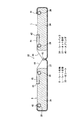
次に図2〜図5を参照して車両用シート装置の構成について説明する。
図2は一方のフロントシート20を取外した状態で示す車両の斜視図、図3は車両用シート装置を示す正面図、図4は図3のA−A線矢視断面図、図5は図3のB−B線矢視断面図であって、左シート31と右シート32とを車幅方向に並設している。
Next, the configuration of the vehicle seat device will be described with reference to FIGS.
2 is a perspective view of the vehicle with one
左右の各シート31,32はそれぞれ座席としてのシート右部Rとシート左部Lとを有すると共に、シート右部Rおよびシート左部Lはそれぞれシートクッション33とシートバック34とを備えている。
上述のシート右部Rとシート左部Lとは車幅方向に分割されて並設されると共に、これらのシート右部Rおよびシート左部Lはそれぞれ車体に対して車幅方向に移動可能に支持されている。
Each of the left and
The seat right portion R and the seat left portion L described above are divided and arranged side by side in the vehicle width direction, and the seat right portion R and the seat left portion L are movable in the vehicle width direction with respect to the vehicle body. It is supported.
左シート31においてシート右部Rのシートバック34と、シート左部Lのシートバック34とはサブシート部材としてのネット部材35で接続され、シート右部Rのシートクッション33と、シート左部Lのシートクッション33とはサブシート部材としてのネット部材36で接続されている。
In the
同様に、右シート32においてシート右部Rのシートバック34と、シート左部Lのシートバック34とはサブシート部材としてのネット部材37で接続され、シート右部Rのシートクッション33と、シート左部Lのシートクッション33とはサブシート部材としてのネット部材38で接続されている。
Similarly, in the
上述のネット部材35,37はシートバック34,34同士を接続するシート状のもので、シート右部Rとシート左部Lとの寸法変更時(寸法縮小時)にはシートバック34,34間に収納可能に構成されている。
The
同様に、上述のネット部材36,38はシートクッション33,33同士を接続するシート状のもので、シート右部Rとシート左部Lとの寸法変更時(寸法縮小時)にはシートクッション33,33間に収納可能に構成されている。
図5を参照して右シート32側のシートバック34,34同士を接続するネット部材37の収納構造について説明すると、シートバック34はシートバックフレーム39を備える一方、シートバック34のウレタン層などから成るクッション部の背もたれ面側に張設したネット部材37の右端部をシート右部Rのシートバック34の側面から背面に回り込ませて、この回り込ませた端部を固定部材40によりシート右部Rの右側のシートバックフレーム39に固定している。
Similarly, the above-described
Referring to FIG. 5, the storage structure of the
またネット部材37の左端部をシート左部Lのシートバック34の側面から背面に回り込ませて、この回り込ませた端部を固定部材41によりシート左部Lの左側のシートバックフレーム39に固定している。
さらにシート右部Rとシート左部Lの各シートバック34の背面部にはリテーナ42をそれぞれ設ける一方、ネット部材37の中間部は一体化して後方に折り曲げ、この折り曲げ端部には保持具43を設けて、この保持具43と左右の各リテーナ42との間を、ワイヤ44およびスプリング45を介して連結し、ネット部材37の中間部をシートバック34,34間の背面側に常時バネ付勢している。
Further, the left end portion of the
Further, a
なお、上述のスプリング45に代えて巻取り装置を用いてもよい。また、図5においては、右シート32側のネット部材37の収納構造について図示したが、左シート31側のネット部材35の収納構造は右側のそれと同様に構成されている。
A winding device may be used instead of the
次に、図3を参照して左シート31および右シート32のシートクッション33,33同士を接続するネット部材36,38の収納構造について説明する。
Next, the storage structure of the
シートクッション33はシートパン46を備える一方、シートクッション33のウレタン層などから成るクッション部の着座面側に張設したネット部材36,38の右端部をシート右部Rのシートクッション33の側面から下面に回り込ませて、この回り込ませた端部をシートパン46下面に固定している。
While the
またネット部材36,38の左端部をシート左部Lのシートクッション33の側面から下面に回り込ませて、この回り込ませた端部をシートパン46下面に固定している。
Further, the left end portions of the
さらにネット部材36,38の中間部は一体化して、下方に折り曲げ、この折り曲げ端部と後述する下部レール73のロアレール74との間をスプリング47で連結し、ネット部材36,38の中間部をシートクッション33,33間の下面側に常時バネ付勢している。
Further, the intermediate portions of the
このようにシートバック34,34同士を接続するネット部材35,37をシートバック34,34間の背面側に付勢すると共に、シートクッション33,33同士を接続するネット部材36,38をシートクッション33,33間の下面側に付勢すると、シート右部Rとシート左部Lとを車幅方向に移動させて、両者R,L間の寸法を縮小変更する時、上述の各ネット部材35〜38はシートバック34,34間またはシートクッション33,33間に収納される(図10参照)。
Thus, the
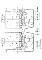
次に図6、図7、図8を参照してリヤシート30のヘッドレストの支持構造について説明する。
シート右部Rおよびシート左部Lの上部にはヘッドレスト50を設けるが、このヘッドレスト50はシート右部Rとシート左部Lの車幅方向の寸法変更時に可及的両者R,L間の中央上部に位置するように構成されている。
Next, the headrest support structure of the
A
図6に示す実施例においては、シート右部Rのシートバック34におけるシート左部L寄りの部位に一対のポールガイド51,51を取付ける一方、これら一対のポールガイド51,51に対応したヘッドレストポール52,52が一体形成されたヘッドレストフレーム53を設け、このヘッドレストフレーム53でヘッドレスト50を支持させて、所謂ヘッドレスト50をシート右部Rに片持ち支持させている。
In the embodiment shown in FIG. 6, a pair of pole guides 51, 51 are attached to a portion of the seat back 34 of the right seat R near the seat left portion L, while headrest poles corresponding to the pair of pole guides 51, 51 are installed. A
図7に示す実施例においては、シート右部Rのシートバック34左部と、シート左部Lのシートバック34右部とにそれぞれポールガイド51,51を取付ける一方、ヘッドレスト50内には、車幅方向に延びる長孔54をもったプレート55を設け、下端部にヘッドレストポール52が一体形成されたヘッドレストフレーム56を上述のプレート55に固定する一方、プレート55の長孔54に沿って車幅方向に移動可能なヘッドレストポール57を設け、このヘッドレストポール57の上部を長孔54に貫通挿入すると共に、長孔54の上下両部に対応して上述のヘッドレストポール57には抜け止め部材58,58を取付け、シート幅の変更時にヘッドレストポール57が長孔54に沿って車幅方向に移動するように構成したものである。
In the embodiment shown in FIG. 7, pole guides 51 and 51 are attached to the left part of the seat back 34 of the right seat R and the right part of the seat back 34 of the left seat L, respectively. A
図8に示す実施例においては、シート右部Rのシートバック34左部と、シート上部Lのシートバック34右部とにそれぞれポールガイド51,51を取付ける一方、一側のポールガイド51に対応して、下部にヘッドレストポール52が一体形成されたヘッドレストフレーム56を設け、他側のポールガイド51に対応して、下部にヘッドレストポール59が一体化されたパイプ状のヘッドレストフレーム60を設けて、この他側のパイプ状のヘッドレストフレーム60内に一側のヘッドレストフレーム56を相対移動可能に挿入して、シート幅の変更時に各ヘッドレストフレーム56,60が車幅方向へ相対移動するように構成したものである。
In the embodiment shown in FIG. 8, pole guides 51 and 51 are attached to the left part of the seat back 34 of the seat right part R and the right part of the seat back 34 of the seat upper part L, respectively, while corresponding to the
上述の図6、図7または図8に示す何れの構造を採用しても、シート右部Rとシート左部Lの車幅方向の寸法変更時にヘッドレスト50を可及的両者R,L間の中央上部に位置させることができる。
次に、図3、図4を参照して、左シート31および右シート32の支持構造、並びにシートスライド構造について説明する。なお、これらの支持構造、シートスライド構造は左右同様かつ左右独立して構成されている。
Regardless of the structure shown in FIG. 6, FIG. 7, or FIG. 8, the
Next, a support structure for the
フロアパネル4の上面に一対のブラケット70,70を離間固定し、これらブラケット70,70間に横架した下部支軸71にリンクプレート72の基端部を取付けている。
A pair of
一方、車幅方向に延びる前後一対の下部レール73,73(図4参照)を設けている。
この下部レール73はロアレール74とアッパレール75とを有するもので、アッパレール75はシート右部Rおよびシート左部Lに対応するように1本のロアレール74当り2本のアッパレール75,75が設けられている。
On the other hand, a pair of front and rear
The
そして、このアッパレール75と各シートパン46との間には車両の前後方向に延びる上部レール76が介設されている。この上部レール76はロアレール77とアッパレール78とを有するもので、アッパレール78はシートパン46に連結固定され、ロアレール77は下部レール73側のアッパレール75に連結固定されている。
An
シート右部Rおよびシート左部Lを車幅方向に横スライドさせる下部レール73と、シート右部Rおよびシート左部Lを車両の前後方向に縦スライドさせる上部レール76とは平面から見て井型形状に組合され、シート支持剛性の向上を図るように構成している。
A
上述の下部レール73,73におけるロアレール74,74の下面には一対のブラケット79,79を離間固定し、これらブラケット79,79間に横架した上部支軸80にリンクプレート72の遊端部を取付けている。ここで、前後一対の下部レール73,73と、一対のブラケット79,79とは平面から見て井型形状に組合わされ、シート支持剛性の向上を図るように構成している。
A pair of
図4に示すように上述のブラケット79はそのノーマル状態下にあってはリヤフロア6上面に沿って所定量後方に延設されるもので、このノーマル位置のブラケット79は図示しないロック部材によりアンロック可能にリヤフロア6に係合される。
As shown in FIG. 4, in the normal state, the
上述の下部レール73と上部レール76との組合わせにより、座席としてのシート右部Rとシート左部Lとの車幅方向の寸法が変更可能に構成されている。また上述のシート右部Rそシート左部Lとは下部レール73に沿って左右方向に移動して車幅方向の寸法が縮小および拡大可能に構成されると共に、上部レール76に沿って車両の前後方向に移動し得るように構成されている。
By combining the
このように構成した車両用シート装置のシートアレンジについて以下に詳述する。
図1〜図4は3人掛けベンチシートモードを示し、左シート31および右シート32のそれぞれのシート右部Rとシート左部Lとは離間設定され、この離間設定されたシート右部Rとシート左部Lとの間は左右に張設された状態下のネット部材35,36,37,38で接続されている。また、図3に示すように左シート31のシートミ右部Rと右シート32のシート左部Lとは当接または近接されている。
The seat arrangement of the vehicle seat device configured as described above will be described in detail below.
1 to 4 show a three-seat bench seat mode, in which the seat right portion R and the seat left portion L of each of the
図9、図10は2人掛けセパレートシートモードを示す。図1〜図4の3人掛けベンチシートモードのリヤシート30を図9、図10の2人掛けセパレートシートモードに変更するには、左シート31のシート右部Rを下部レール73に沿って車外側へ移動して、シート左部Lに当接または近接させる。
9 and 10 show the two-seat separate sheet mode. In order to change the
同様に、右シート32のシート左部Lと下部レール73に沿って車外側へ移動して、シート右部Rに当接または近接させる。
この場合、ネット部材35,37はスプリング45のバネ力によりシートバック34,34間に収納され、ネット部材36,38はスプリング47のバネ力によりシートクッション33,33間に収納され、ネット部材36,38はスプリング47のバネ力によりシートクッション33,33間に収納され、図9、図10に示す2人掛けセパレートシートモードとなる。
Similarly, it moves to the vehicle outer side along the seat left portion L of the
In this case, the
図11、図12、図13は内寄せリムジンモードを示す。
図1〜図4の3人掛けベンチシートモードのリヤシート30を図11〜図13の内寄せリムジンモード(2人掛けリムジンモード)に変更するには、左シート31のシート左部Lを下部レール73に沿って車内側へ移動して、シート右部Rに当接または近接させる。
11, 12, and 13 show the inward limousine mode.
In order to change the
同様に右シート32のシート右部Rを下部レール73に沿って車内側へ移動して、シート左部Lに当接または近接させる。この場合、ネット部材35,37はスプリング45のバネ力によりシートバック34,34間に収納され、ネット部材36,38はスプリング47のバネ力によりシートクッション33,33間に
収納される。
Similarly, the seat right portion R of the
この内寄せ状態の左シート31および右シート32を車両の前後方向に延びる上部レール76に沿って後退移動させ、これらの各シート31,32を左右のホイールハウス11,11間に位置させると、図11、図12、図13に示す内寄席リムジンモードとなる。
When the
図14、図15、図16はフラットフロアモードを示す。図1〜図4の3人掛けベンチシートモードのリヤシート30を図14〜図16のフラットフロアモードに変更するには、まず、ヘッドレスト50,50を取外す。
次に左シート31および右シート32の各シート部Rおよびシート左部Lを下部レール73に沿って内寄せ移動させる。次にシートバック34をリクライニングナックルのリクライニング支点(図示せず)を中心としてシートクッション33上部に前倒させて折り畳む。
14, 15 and 16 show the flat floor mode. In order to change the
Next, the seat portion R and the seat left portion L of the
次に、この折り畳み状態を保持したまま下部支軸71を中心としてリンクプレート72を介してブラケット79、下部レール73、シートクッション33、シートバック34を一体的に前方かつ下方に移動させて、フロアパネル4上に格納すると、図14〜図16のフラットフロアモードとなり、この場合、折り畳み及び格納されたシートバック34の背面はリヤフロア6に対してフラット(面一または略面一)となり、荷室スペース拡大を図ることができる。
Next, the
この場合、図17に示すようにブラケット70,79の寸法設定により、フロアパネル4側のブラケット70の上端にブラケット79の延長部が上載され、ブラケット79の折り曲げ部下端がフロアパネル4上面に当接して、各要素72,79,73,76,33,34の水平状態を保持すべく構成してもよい。
In this case, as shown in FIG. 17, by setting the dimensions of the
また上述の車両用シート装置が搭載される車両の車体構造は、図1の構造に代えて図18の構造であってもよい。つまり図18に示す構造は、トンネル部8が幅広部8aと幅狭部8bとを有し、幅広部8aに対応してトンネル部8を跨いで左右のサイドシル7,7まで車幅方向に延びるクロスメンバ14(いわゆるNo.2クロスメンバ)を設ける一方、このクロスメンバ14よりも後方に離間した位置には、幅狭部8bとサイドシル7との間を車幅方向に連結する左右一対の別のクロスメンバ15(いわゆるNo.2.5メンバ)を設け、これら前後の各クロスメンバ14,15の上部にフロントシート20,20を配設する一方、リヤフロア6の中間部にはスペアタイヤパン16を段下げ形成したものである。
Further, the vehicle body structure of the vehicle on which the above-described vehicle seat device is mounted may be the structure of FIG. 18 instead of the structure of FIG. That is, in the structure shown in FIG. 18, the
なお、図中17はフロント側のクロスメンバ、18はキックアップ部5とリヤフロア6とのコーナ部背面に接合固定されたリヤフロアクロスメンバであり、また上述のトンネル部8の車外側にはトンネル部形状と対応する形状の燃料タンクを配設すべく構成してもよい。
In the figure, 17 is a cross member on the front side, 18 is a rear floor cross member joined and fixed to the rear surface of the corner portion of the kick-up
このように上記実施例の車両用シート装置は、車幅方向に複数に分割されて並設した座席(シート右部R、シート左部L参照)を有する車両用シート装置であって、上記座席(シート右部R、シート左部L参照)はそれぞれが車体に対して車幅方向に移動可能に支持される一方、上記座席(シート右部R、シート左部L参照)の間を接続し、かつ座席(シート右部R、シート左部L参照)間に収納可能なシート状態のサブシート部材(ネット部材35〜38参照)を設け、上記座席(シート右部R、シート左部L参照)の車幅方向の寸法が変更可能に構成されたものである。
As described above, the vehicle seat device according to the above-described embodiment is a vehicle seat device having a seat (see the seat right portion R and the seat left portion L) which is divided into a plurality in the vehicle width direction and arranged side by side. (See the seat right portion R and the seat left portion L) are supported so as to be movable in the vehicle width direction with respect to the vehicle body, and connect between the seats (see the seat right portion R and the seat left portion L). In addition, a sub-seat member (see
この構成によれば、上述のシート状のサブシート部材(ネット部材35〜38参照)で座席(シート右部R、シート左部L参照)間を接続したので、それぞれの座席(シート右部R、シート左部L参照)の近接または離間により座席の車幅方向の寸法を容易に変更することができ、また座席(シート右部R、シート左部L参照)の近接時には上記シート状のサブシート部材(ネット部材35〜38参照)は座席間に収納される。
According to this configuration, since the seats (see the seat right portion R and the seat left portion L) are connected by the above-described sheet-like sub-seat members (see the
この結果、リヤシート30の前後方向のスペースに影響を与えることなく、リヤシート30の幅を可変とすることができ、リヤシート30の移動とスペースの有効活用との両立を図ることができるうえ、構造のシンプル化を達成することができる。
As a result, the width of the
また、上記座席(シート右部R、シート左部L参照)のそれぞれはシートクッション33とシートバック34とを備え、上記シートクッション33,33同士が上記サブシート部材(ネット部材36,38参照)にて接続されたものである。
Each of the seats (see the seat right portion R and the seat left portion L) includes a
この構成によれば、シートクッション33,33同士がサブシート部材(ネット部材36,38参照)で接続されているので、座り心地(乗り心地)がよく、しかも車幅方向の幅の変更も容易となる。
According to this configuration, since the seat cushions 33 and 33 are connected to each other by the sub seat members (see the
さらに、上記座席(シート右部R、シート左部L参照)のそれぞれはシートクッション33とシートバック34とを有し、シートバック34,34同士が上記サブシート部材(ネット部材35,37参照)で接続されたものである。
Further, each of the seats (see the seat right part R and the seat left part L) has a
この構成によれば、シートバック34,34同士がサブシート部材(ネット部材35,37参照)で接続されているので、背もたれ性がよく、しかも車幅方向の幅の変更も容易となる。
According to this configuration, since the seat backs 34 and 34 are connected to each other by the sub seat members (see the
加えて、上記サブシート部材(ネット部材35〜38参照)の中間部は付勢部材(スプリング45,47参照)によりシートクッション33,33間の下面側またはシートバック34,34間の背面側に付勢されたものである。
この構成によれば、シート幅の縮小時においてサブシート部材(ネット部材35〜38参照)が撓まないので、見栄えの向上を図ることができる。
In addition, the intermediate portion of the sub-seat member (see the
According to this configuration, since the sub-sheet member (see the
この発明の一実施態様においては、また上記サブシート部材はネット状の部材35〜38に設定されたものである。
この構成によれば、サブシート部材(ネット部材35〜38参照)の網目構造により弾力性を有するので、座り心地または/および背もたれ性の向上を図ることができる。
In one embodiment of the present invention, the sub-sheet member is a net-like member 35-38.
According to this structure, since it has elasticity with the mesh structure of a sub sheet | seat member (refer net members 35-38), the improvement of sitting comfort or / and a backrest property can be aimed at.
さらに、上記座席(シート右部R、シート左部L参照)は左右前後方向(つまり車幅方向と車両の前後方向)に移動して車幅方向の寸法が縮小可能に構成されたものである。
この構成によれば、座席(シート右部R、シート左部L参照)が車両の左右前後方向に移動できるので、シートアレンジ性の向上を図ることができる。
しかも、上記座席(シート右部R、シート左部L参照)の後方には車幅方向内方に車室2側へ突出した一対のホイールハウス11,11が設けられ、上記座席は一対のホイールハウス11,11間に移動可能に構成されたものである。
Further, the seat (see the seat right portion R and the seat left portion L) is configured to move in the left-right front-rear direction (that is, the vehicle width direction and the vehicle front-rear direction) so that the dimensions in the vehicle width direction can be reduced. .
According to this configuration, since the seat (see the seat right part R and the seat left part L) can move in the left-right and front-rear directions of the vehicle, the seat arrangement can be improved.
Moreover, a pair of wheel houses 11, 11 projecting inward in the vehicle width direction toward the
この構成によれば、座席(シート右部R、シート左部L参照)が一対のホイールハウス11,11間に移動し得るので、座席に着座する後席乗員の快適性向上を図ることができる。 According to this configuration, since the seat (see the seat right part R and the seat left part L) can move between the pair of wheel houses 11, 11, it is possible to improve the comfort of the rear seat occupant seated on the seat. .
また、車幅方向に複数に分割され、かつ上記サブシート部材(ネット部材35〜38参照)で接続された座席対(左シート31、右シート32参照)が、車幅方向左右に並設されて成るものである。
A pair of seats (see the
この構成によれば、座席対(左シート31、右シート32参照)のぺア構造により、シートアレンジの多様化を図ることができる。
さらに、上記座席(シート右部R、シート左部L参照)はシートクッション33上方にシートバック34を前倒させてフロアパネル4上に格納可能に構成されたものである。
この構成によれば、座席(シート右部R、シート左部L参照)の格納時に荷室スペースの拡大を図ることができる。
According to this configuration, the seat arrangement can be diversified by the pair structure of the seat pair (see the
Further, the seat (see the seat right portion R and the seat left portion L) is configured to be retractable on the
According to this configuration, the luggage space can be expanded when the seat (see the seat right part R and the seat left part L) is stored.
この発明の構成と、上述の実施例との対応において、
この発明の車幅方向に複数に分割されて並設した座席は、実施例のシート右部Rとシート左部Lとに対応し、
以下同様に、
シート状のサブシート部材は、ネット部材35〜38に対応し、
付勢部材は、スプリング45,47に対応し、
サブシート部材で接続された座席対は、左シート31、右シート32に対応するも、
この発明は上述の実施例の構成のみに限定されるものではない。
In the correspondence between the configuration of the present invention and the above-described embodiment,
The seats divided into a plurality in the vehicle width direction of the present invention and arranged side by side correspond to the seat right portion R and the seat left portion L of the embodiment,
Similarly,
The sheet-like sub-sheet member corresponds to the
The biasing member corresponds to the
The pair of seats connected by the sub seat member corresponds to the
The present invention is not limited to the configuration of the above-described embodiment.
例えば、上記実施例においては、車両の前後方向に複数列(2列)配設されたフロントシート20とリヤシート30とのうちの第2列目シートに車両用シート装置を適用したが、車両の前後方向に合計3列または合計4列配設されたシート構造において、ホイールハウス11に近接された後列のシートに上述の車両用シート装置を適用してもよいことは勿論である。
For example, in the above embodiment, the vehicle seat device is applied to the second row seat of the
R…シート右部(座席)
L…シート左部(座席)
2…車室
4…フロアパネル
11…ホイールハウス
31…左シート(座席対)
32…右シート(座席対)
33…シートクッション
34…シートバック
35,36,37,38…ネット部材(サブシート部材)
45,47…スプリング(付勢部材)
R ... Seat right (seat)
L ... Seat left (seat)
2 ...
32 ... Right seat (seat pair)
33 ...
45, 47 ... Spring (biasing member)
Claims (9)
上記座席はそれぞれが車体に対して車幅方向に移動可能に支持される一方、
上記座席の間を接続し、かつ座席間に収納可能なシート状態のサブシート部材を設け、上記座席の車幅方向の寸法が変更可能に構成された
車両用シート装置。 A vehicle seat device having a seat divided into a plurality in the vehicle width direction and arranged side by side,
Each of the seats is supported so as to be movable in the vehicle width direction with respect to the vehicle body,
A vehicular seat device configured to provide a sub-seat member in a seat state that connects between the seats and can be stored between the seats, and is capable of changing a dimension in a vehicle width direction of the seat.
上記シートクッション同士が上記サブシート部材にて接続された
請求項1記載の車両用シート装置。 Each of the above seats comprises a seat cushion and a seat back,
The vehicle seat device according to claim 1, wherein the seat cushions are connected by the sub seat member.
請求項1または2記載の車両用シート装置。 Each of the said seats has a seat cushion and a seat back, The vehicle seat apparatus of Claim 1 or 2 with which the seat backs were connected by the said sub seat member.
請求項2または3記載の車両用シート装置。 4. The vehicle seat device according to claim 2, wherein the intermediate portion of the sub seat member is urged toward the lower surface of the seat cushion or the back surface of the seat back by the urging member.
請求項1〜4の何れか1に記載の車両用シート装置。 The vehicle seat device according to any one of claims 1 to 4, wherein the sub-seat member is a net-like member.
請求項1〜5の何れか1に記載の車両用シート装置。 The vehicle seat device according to any one of claims 1 to 5, wherein the seat is configured to move in the left-right and front-rear directions so that the size in the vehicle width direction can be reduced.
上記座席は一対のホイールハウス間に移動可能に構成された
請求項1〜6記載の何れか1に記載の車両用シート装置。 A pair of wheel houses projecting toward the passenger compartment side inward in the vehicle width direction are provided behind the seat,
The vehicle seat device according to any one of claims 1 to 6, wherein the seat is configured to be movable between a pair of wheel houses.
請求項1〜7の何れか1に記載の車両用シート装置。 The vehicle seat device according to any one of claims 1 to 7, wherein a pair of seats divided into a plurality in the vehicle width direction and connected by the sub-seat members are arranged side by side in the vehicle width direction.
請求項2〜8の何れか1に記載の車両用シート装置。
9. The vehicle seat device according to claim 2, wherein the seat is configured to be retractable on a floor panel with a seat back tilted above a seat cushion. 10.
Priority Applications (1)
| Application Number | Priority Date | Filing Date | Title |
|---|---|---|---|
| JP2004117441A JP2005297788A (en) | 2004-04-13 | 2004-04-13 | Seat device for vehicle |
Applications Claiming Priority (1)
| Application Number | Priority Date | Filing Date | Title |
|---|---|---|---|
| JP2004117441A JP2005297788A (en) | 2004-04-13 | 2004-04-13 | Seat device for vehicle |
Publications (1)
| Publication Number | Publication Date |
|---|---|
| JP2005297788A true JP2005297788A (en) | 2005-10-27 |
Family
ID=35329857
Family Applications (1)
| Application Number | Title | Priority Date | Filing Date |
|---|---|---|---|
| JP2004117441A Pending JP2005297788A (en) | 2004-04-13 | 2004-04-13 | Seat device for vehicle |
Country Status (1)
| Country | Link |
|---|---|
| JP (1) | JP2005297788A (en) |
-
2004
- 2004-04-13 JP JP2004117441A patent/JP2005297788A/en active Pending
Similar Documents
| Publication | Publication Date | Title |
|---|---|---|
| US7708331B2 (en) | Seat device of vehicle | |
| US10189373B2 (en) | Seat arrangement | |
| JP4649864B2 (en) | Vehicle seat system | |
| CN102059965A (en) | Seat system for a vehicle | |
| JP5706143B2 (en) | Sheet | |
| JP2022186996A (en) | Vehicular seat | |
| JP2008284901A (en) | Structure of inside of cabin of automobile | |
| JP4349116B2 (en) | Vehicle fuel tank arrangement structure | |
| JP2005297788A (en) | Seat device for vehicle | |
| JP4106657B2 (en) | Seat back structure | |
| JP4412032B2 (en) | Vehicle seat device | |
| JP2005289137A (en) | Seat device for vehicle | |
| JP4442389B2 (en) | Vehicle seat device | |
| JP3870805B2 (en) | Vehicle seat device | |
| JP4561161B2 (en) | Vehicle seat device | |
| JP2007253669A (en) | Vehicle seat device | |
| JP2005170296A (en) | Lower part vehicle body structure of vehicle | |
| JP4165200B2 (en) | Auxiliary seat device for vehicle | |
| JP4380417B2 (en) | Vehicle seat device | |
| JP2007245744A (en) | Vehicular seat device | |
| JP5445911B2 (en) | Structure of vehicle seat | |
| JP5418143B2 (en) | Vehicle seat device | |
| JP2004217011A (en) | Vehicle sheet device | |
| JP2009227067A (en) | Vehicle body structure | |
| JP2009023586A (en) | Seat device for vehicle |
Legal Events
| Date | Code | Title | Description |
|---|---|---|---|
| A621 | Written request for application examination |
Effective date: 20070219 Free format text: JAPANESE INTERMEDIATE CODE: A621 |
|
| A977 | Report on retrieval |
Effective date: 20090416 Free format text: JAPANESE INTERMEDIATE CODE: A971007 |
|
| A131 | Notification of reasons for refusal |
Free format text: JAPANESE INTERMEDIATE CODE: A131 Effective date: 20090421 |
|
| A02 | Decision of refusal |
Effective date: 20090915 Free format text: JAPANESE INTERMEDIATE CODE: A02 |