JP2005297635A - Electric power unit - Google Patents
Electric power unit Download PDFInfo
- Publication number
- JP2005297635A JP2005297635A JP2004113248A JP2004113248A JP2005297635A JP 2005297635 A JP2005297635 A JP 2005297635A JP 2004113248 A JP2004113248 A JP 2004113248A JP 2004113248 A JP2004113248 A JP 2004113248A JP 2005297635 A JP2005297635 A JP 2005297635A
- Authority
- JP
- Japan
- Prior art keywords
- power
- transporter
- power supply
- instrument
- power generation
- Prior art date
- Legal status (The legal status is an assumption and is not a legal conclusion. Google has not performed a legal analysis and makes no representation as to the accuracy of the status listed.)
- Pending
Links
- 238000010248 power generation Methods 0.000 claims description 32
- 238000004804 winding Methods 0.000 description 3
- 238000004378 air conditioning Methods 0.000 description 2
- 238000005034 decoration Methods 0.000 description 2
- 238000000034 method Methods 0.000 description 2
- 239000000725 suspension Substances 0.000 description 2
- 230000005540 biological transmission Effects 0.000 description 1
- 239000002699 waste material Substances 0.000 description 1
Images

Classifications
-
- Y—GENERAL TAGGING OF NEW TECHNOLOGICAL DEVELOPMENTS; GENERAL TAGGING OF CROSS-SECTIONAL TECHNOLOGIES SPANNING OVER SEVERAL SECTIONS OF THE IPC; TECHNICAL SUBJECTS COVERED BY FORMER USPC CROSS-REFERENCE ART COLLECTIONS [XRACs] AND DIGESTS
- Y02—TECHNOLOGIES OR APPLICATIONS FOR MITIGATION OR ADAPTATION AGAINST CLIMATE CHANGE
- Y02T—CLIMATE CHANGE MITIGATION TECHNOLOGIES RELATED TO TRANSPORTATION
- Y02T30/00—Transportation of goods or passengers via railways, e.g. energy recovery or reducing air resistance
Landscapes
- Charge And Discharge Circuits For Batteries Or The Like (AREA)
Abstract
Description
この発明はロープウエイと共に用いて、ロープウエイの搬器に搭載された電気機器に電力を供給するための電源装置に関するものである。 The present invention relates to a power supply device that is used together with a ropeway to supply electric power to an electric device mounted on a ropeway carrier.
一般に索道方式輸送設備として知られているロープウエイ等の索道方式は、2つの地点間に張り渡されて循環する索道を握索して索道とともに走行する搬器(ゴンドラ)を備えたものである。(例えば特許文献1参照)また、固定張架された索道上を車輪によって走行可能に支持されて、牽引ロープにより索道に沿って走行する搬器を備えたものもある。 A cableway system such as a ropeway generally known as a cableway system transportation facility is equipped with a carrier (gondola) that grips a circulating cableway that stretches between two points and travels with the cableway. (For example, refer patent document 1) Moreover, there is also a thing equipped with the carrying device which is supported so that it can drive | work on the cableway fixedly stretched by the wheel, and it travels along a cableway by a tow rope.
ロープウエイの搬器内には、空調設備、照明設備および無線装置などが搭載されており、また搬器外部には電飾や広告装置などを設けてあることがある。これらの電気機器を作動させるための電力を供給する電源装置としては、搬器内に搭載されたバッテリーが用いられていた。 The ropeway carrier is equipped with air conditioning equipment, lighting equipment, radio equipment, and the like, and the exterior of the equipment may be equipped with electrical decorations, advertising devices, and the like. As a power supply device for supplying electric power for operating these electric devices, a battery mounted in a transporter has been used.
上述のような従来のロープウエイに於いては、搬器に搭載された電気機器用の電源装置としてのバッテリーの充電は、搬器が停止する終点駅にバッテリー電源を設置し、搬器が終点駅で停止した非運行時に、パンタグラフ式の伸縮式連結端子を搬器側から伸展させて駅側に設置した電源端子に電気的に連結して充電するようにしていた。しかしながら、この方式では、例えば搬器が終点駅に非運行状態で停止しているときなどの比較的長時間の停止時にだけしかバッテリー充電ができない。ロープウエイの走行中には、搬器に設置された様々な電気機器は充電式電源装置だけで駆動しなければならず、搬器では大電力の使用も、長時間の使用もできず、電源装置としての性能が制限されていた。 In the conventional ropeway as described above, charging of the battery as the power supply device for the electric equipment mounted on the carrier is installed at the terminal station where the carrier stops, and the carrier stops at the terminal station. During non-operation, the pantograph-type telescopic connection terminal was extended from the transporter side and electrically connected to the power supply terminal installed on the station side for charging. However, in this method, for example, the battery can be charged only when the transporter is stopped at a terminal station in a non-operating state, for example, when it is stopped for a relatively long time. During the travel of the ropeway, various electrical devices installed in the transporter must be driven only by the rechargeable power supply, and the transporter cannot be used for high power or for a long time. Performance was limited.
従って、この発明の目的は、上述の課題を解決し、ロープウエイの走行中にも搬器の電気機器に電力を供給できる電源装置を提供することである。 Accordingly, an object of the present invention is to solve the above-described problems and to provide a power supply device that can supply electric power to the electric equipment of the transporter while the ropeway is traveling.
この発明によれば、張り渡されたロープによって支持されて上記ロープに沿って移動し、電気機器が搭載された搬器を備えたロープウエイと共に用い、上記電気機器に電力を供給するための電源装置に於いて、上記搬器に設けられて、上記搬器が走行中に外部から受けるエネルギーを上記電気機器に供給する電力に変換する発電装置を備えたことを特徴とする電源装置が得られる。 According to the present invention, a power supply device for supplying electric power to the electric device, which is supported by a stretched rope and moves along the rope, is used together with a ropeway provided with a carrying device on which the electric device is mounted. In this case, a power supply device is provided that includes a power generation device that is provided in the transporter and converts energy received from the outside during travel of the transporter into power supplied to the electrical equipment.
発電装置は、搬器の走行車輪によって駆動される発電機としても、走行風等の風で回転する風車によって駆動される発電機としても、走行時に太陽光を受ける太陽光発電パネルとしても良い。また、搬器には、発電装置が発電した電力を蓄える蓄電池を備えることも、電力の電圧調整をする電圧調整器を備えることもできる。 The power generation device may be a generator driven by traveling wheels of a transporter, a generator driven by a windmill rotating with wind such as traveling wind, or a solar power generation panel that receives sunlight during traveling. In addition, the transporter can include a storage battery that stores the power generated by the power generation device, or a voltage regulator that adjusts the voltage of the power.
この発明の電源装置によれば、搬器の走行中に外部から受けるエネルギーを電力に変換して電気機器に供給でき、搬器の電気機器に供給する電力の制限が緩和される。 According to the power supply device of the present invention, the energy received from the outside during traveling of the transporter can be converted into electric power and supplied to the electric device, and the restriction on the electric power supplied to the electric device of the transporter is relaxed.
実施の形態1.
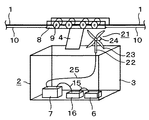
図1にはこの発明の電源装置を搭載したロープウエイを概略的に示してある。このロープウエイは、図示してない二駅間に張り渡された索道としてのロープ1を備え、このロープ1によって支持されてロープ1に沿って移動できる搬器(ゴンドラ)2を備えている。搬器2は、乗客乗員あるいは貨物を乗せるための搬器本体3と、搬器本体3の天井から上方に突出した懸垂腕部4に回転可能に設けられた走行車輪5と、走行中にも作動すべき電気機器6とを備えている。
FIG. 1 schematically shows a ropeway equipped with the power supply device of the present invention. The ropeway includes a
走行車輪5は、懸垂腕部4の上端に設けられたブラケット8に車軸9を介して回転自在に取付られていて、ロープ1上を転動して、搬器2がロープ1に沿って案内支持されつつ走行できるようにするものである。電気機器6は、図には模式的にブロックで表してあるが、搬器内部に搭載される空調設備、照明設備および無線装置など、また搬器外部に搭載される電飾や広告装置などをも含むものである。搬器にはまた、電気機器6を作動させる電力を供給するためにバッテリー7が搭載されている。また搬器2をロープ1に沿って走行させるための牽引索10の一端がブラケット8に結合されていて、牽引索10の他端は、図示してないが終点駅等に設けた巻き取りドラムに接続されていて、巻き取りドラムによる巻き取り、繰り出しにより、搬器2をロープ1に沿って走行できるようにしてある。
The
この発明によれば、搬器2に搭載された電気機器6を作動させる電力を供給するため電源装置は、搬器2に設けられていて、搬器2が走行中に外部から受けるエネルギーを電気機器6に供給する電力に変換する発電装置11を備えている。走行中の搬器2が外部から受けるエネルギーとは、図1に示す例では、走行車輪5がロープ1上を転動する際にロープ1から受ける回転力である。従って図示の発電装置11は、4つの走行車輪5の車軸9にそれぞれ直接連結されて駆動される回転入力軸12を持つ4台の発電機13を備えている。各発電機13はケーブル14によって搬器本体3に設けられたバッテリー7に接続されていて、発電機13で発電された電力をバッテリー7に蓄電できるようにしてある。バッテリー7はケーブル15によって電圧調整器16を介して電気機器6に接続されている。このように、この発明によれば、搬器2に搭載された電気機器6を作動させる電力を供給するため電源装置は発電装置11であり、図1に示す例では、発電装置11の他にバッテリー7および電圧調整器16をも含んでいて、発電機13が駆動されていない時にも安定した電力供給ができるようにしてある。
According to the present invention, the power supply device is provided in the
この発明の電源装置は、ロープウエイの停止時に例えば終点駅に設けた外部電源に接続できるようにして、外部電源と搬器内電源とを併用することもできる。また、図示の発電装置11は、走行車輪5に回転入力軸12がそれぞれ直接連結された発電機13を備えているが、ギヤ等の適当な動力伝達機構、変速機構、クラッチ機構等を介して連結し、変速可能、選択的あるいは逆転可能に連結することもできるし、一台の発電機に複数の走行車輪5を並列に連結することもできる。
The power supply device of the present invention can be used in combination with an external power supply and a power supply in a portable unit so that it can be connected to an external power supply provided at, for example, an end station when the ropeway is stopped. In addition, the illustrated
この発明の電源装置によれば、搬器2の走行中にロープ1上を転動する走行車輪5によって発電機13を回転させて発電し、搬器2に搭載されている電気機器6に電力を供給できるので、ロープウエイの走行中に電力供給が確保でき、搬器2の電気機器6に供給する電力の制限が緩和され、従来よりも大電流の電力を長時間供給することができる。
According to the power supply device of the present invention, the
実施の形態2.
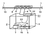
図2に示すロープウエイに於いては、電源装置の発電装置21が、搬器2の搬器本体3の外部に支柱22を介して取り付けられ、搬器2の走行時に走行風や自然風によって回転させられる風車23によって駆動される発電機24を備えている。発電機24はロープウエイの走行時の走行風や自然風によって回転して発電し、電力をケーブル25によってバッテリー7に供給し、そこから電圧調整器16を通して電気機器6に給電する。
In the ropeway shown in FIG. 2, the
実施の形態3.
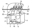
図3のロープウエイに於いては、電源装置の発電装置31が、搬器2の搬器本体3の外部、例えば屋根外面に取り付けられて、走行時に太陽光線を受けて発電する太陽光発電パネル32を備えており、太陽光発電パネル32はケーブル33によって電圧調整器15を通してバッテリー7に接続されている。発電装置31は光により発電された電力をケーブル33によってバッテリー7に供給し、そこから電圧調整器16を通して電気機器6に給電する。
In the ropeway of FIG. 3, the
図2および図3に示す例に於いては、図1の走行車輪5を利用する発電装置11は設けられていないが、発電装置として、図1の発電装置11と図2の風車式の発電装置21と図3の太陽光発電パネル発電装置31とを全てあるいは選択的に併用することもできる。風車23および太陽光発電パネルの取付位置、形状および型式は任意である。またこれらの発電装置を、先に説明したように、バッテリー7の充電を外部電源によって行う方式と併用することもできる。この場合の給電はより安定し、自由度の高いものとなる。
In the example shown in FIGS. 2 and 3, the
実施の形態4.
図4には、電源装置の発電装置として図1の発電装置11、図2の風車式の発電装置21および図3の太陽光発電パネル32の発電装置31を全て併用した例を示す。この構成によれば、電力の供給をより安定させることができる。発電装置11、21および31は発電された電力をそれぞれケーブル14、25および33によってバッテリー7に供給し、そこから電圧調整器16を通して電気機器6に給電する。外部電源出力端子(図示してない)に接続できる充電用の入力端子35もパンタグラフ機構36によって引き込み式に搬器本体3に取り付けられていて、ロープウエイの停止時に駅側の外部電源(図示してない)に接続して、搬器2内のバッテリー7を充電できるようにしてある。
FIG. 4 shows an example in which all of the
1 ロープ、2 搬器、5 走行車輪、6 電気機器、7 バッテリー、16 電圧調整器、11、21、31 発電装置、13 発電機、23 風車、32 太陽光発電パネル。
DESCRIPTION OF
Claims (6)
上記搬器に設けられて、上記搬器が走行中に外部から受けるエネルギーを上記電気機器に供給する電力に変換する発電装置を備えたことを特徴とする電源装置。 In a power supply device that is supported by a stretched rope, moves along the rope, and is used with a ropeway equipped with a transporter on which the electrical equipment is mounted, and supplies power to the electrical equipment.
A power supply device, comprising: a power generation device that is provided in the transporter and converts energy received from outside during travel by the transporter into electric power supplied to the electrical device.
Priority Applications (1)
| Application Number | Priority Date | Filing Date | Title |
|---|---|---|---|
| JP2004113248A JP2005297635A (en) | 2004-04-07 | 2004-04-07 | Electric power unit |
Applications Claiming Priority (1)
| Application Number | Priority Date | Filing Date | Title |
|---|---|---|---|
| JP2004113248A JP2005297635A (en) | 2004-04-07 | 2004-04-07 | Electric power unit |
Publications (1)
| Publication Number | Publication Date |
|---|---|
| JP2005297635A true JP2005297635A (en) | 2005-10-27 |
Family
ID=35329728
Family Applications (1)
| Application Number | Title | Priority Date | Filing Date |
|---|---|---|---|
| JP2004113248A Pending JP2005297635A (en) | 2004-04-07 | 2004-04-07 | Electric power unit |
Country Status (1)
| Country | Link |
|---|---|
| JP (1) | JP2005297635A (en) |
Cited By (7)
| Publication number | Priority date | Publication date | Assignee | Title |
|---|---|---|---|---|
| JP2011246043A (en) * | 2010-05-28 | 2011-12-08 | Osaka Sharyo Kogyo Kk | Gondola for cableway |
| US10727674B2 (en) | 2015-03-19 | 2020-07-28 | Innova Patent Gmbh | System for supplying at least one electrical load or energy storage device with direct current |
| JP2020522424A (en) * | 2017-06-02 | 2020-07-30 | インノヴァ・パテント・ゲゼルシャフト・ミット・ベシュレンクテル・ハフツング | Cable towed carrier and method of operating such carrier |
| KR102216273B1 (en) * | 2019-11-19 | 2021-02-17 | (합)동양아이텍 | Gondola's self-operating system with solar panels |
| CN113353106A (en) * | 2020-03-04 | 2021-09-07 | 长沙戴卡科技有限公司 | Aluminum sample inspection conveying device |
| JP2023513897A (en) * | 2020-02-11 | 2023-04-04 | シャーマン+ライリー,インコーポレイテッド | Hybrid installation equipment and process |
| WO2025019880A1 (en) * | 2023-07-21 | 2025-01-30 | Technische Universität Wien | Drive system equipment |
Citations (8)
| Publication number | Priority date | Publication date | Assignee | Title |
|---|---|---|---|---|
| JPH0454761U (en) * | 1990-09-19 | 1992-05-11 | ||
| JPH04173467A (en) * | 1990-11-08 | 1992-06-22 | Taihei Sakudo Kk | Ropeway device |
| JPH05131920A (en) * | 1991-11-14 | 1993-05-28 | Nippon Cable Co Ltd | Hybrid-type circulation cableway usable with railway |
| JPH0993705A (en) * | 1995-09-21 | 1997-04-04 | Mitsubishi Heavy Ind Ltd | Power supply apparatus for gondola |
| JPH09142293A (en) * | 1995-11-22 | 1997-06-03 | Nippon Cable Co Ltd | Power generating device of driven side pulley of ropeway |
| JP2001182647A (en) * | 1999-12-27 | 2001-07-06 | G & M:Kk | Energy storage system |
| JP2002199502A (en) * | 2000-12-25 | 2002-07-12 | Shoichi Matsui | Vehicles equipped with wind and solar power generators |
| JP2003102104A (en) * | 2001-09-26 | 2003-04-04 | San'eisha Mfg Co Ltd | Portable charging system unit for electric vehicles |
-
2004
- 2004-04-07 JP JP2004113248A patent/JP2005297635A/en active Pending
Patent Citations (8)
| Publication number | Priority date | Publication date | Assignee | Title |
|---|---|---|---|---|
| JPH0454761U (en) * | 1990-09-19 | 1992-05-11 | ||
| JPH04173467A (en) * | 1990-11-08 | 1992-06-22 | Taihei Sakudo Kk | Ropeway device |
| JPH05131920A (en) * | 1991-11-14 | 1993-05-28 | Nippon Cable Co Ltd | Hybrid-type circulation cableway usable with railway |
| JPH0993705A (en) * | 1995-09-21 | 1997-04-04 | Mitsubishi Heavy Ind Ltd | Power supply apparatus for gondola |
| JPH09142293A (en) * | 1995-11-22 | 1997-06-03 | Nippon Cable Co Ltd | Power generating device of driven side pulley of ropeway |
| JP2001182647A (en) * | 1999-12-27 | 2001-07-06 | G & M:Kk | Energy storage system |
| JP2002199502A (en) * | 2000-12-25 | 2002-07-12 | Shoichi Matsui | Vehicles equipped with wind and solar power generators |
| JP2003102104A (en) * | 2001-09-26 | 2003-04-04 | San'eisha Mfg Co Ltd | Portable charging system unit for electric vehicles |
Cited By (9)
| Publication number | Priority date | Publication date | Assignee | Title |
|---|---|---|---|---|
| JP2011246043A (en) * | 2010-05-28 | 2011-12-08 | Osaka Sharyo Kogyo Kk | Gondola for cableway |
| US10727674B2 (en) | 2015-03-19 | 2020-07-28 | Innova Patent Gmbh | System for supplying at least one electrical load or energy storage device with direct current |
| JP2020522424A (en) * | 2017-06-02 | 2020-07-30 | インノヴァ・パテント・ゲゼルシャフト・ミット・ベシュレンクテル・ハフツング | Cable towed carrier and method of operating such carrier |
| US11505215B2 (en) | 2017-06-02 | 2022-11-22 | Innova Patent Gmbh | Cable-drawn conveying device and method for operating such a device |
| KR102216273B1 (en) * | 2019-11-19 | 2021-02-17 | (합)동양아이텍 | Gondola's self-operating system with solar panels |
| JP2023513897A (en) * | 2020-02-11 | 2023-04-04 | シャーマン+ライリー,インコーポレイテッド | Hybrid installation equipment and process |
| CN113353106A (en) * | 2020-03-04 | 2021-09-07 | 长沙戴卡科技有限公司 | Aluminum sample inspection conveying device |
| CN113353106B (en) * | 2020-03-04 | 2023-11-07 | 长沙戴卡科技有限公司 | Aluminum sample inspection transportation device |
| WO2025019880A1 (en) * | 2023-07-21 | 2025-01-30 | Technische Universität Wien | Drive system equipment |
Similar Documents
| Publication | Publication Date | Title |
|---|---|---|
| KR102020277B1 (en) | Canopy for charging device for electric vehicle with charging cable control system of electric vehicle and waiting booth | |
| US8872368B1 (en) | Power generating system using wasting energy from moving objects | |
| US20110100731A1 (en) | Perpetual fuel-free electric vehicle | |
| TW201012732A (en) | Tether handling for airborne electricity generators | |
| US20090277699A1 (en) | Power-generating plug-and-play vehicle | |
| CN101306688A (en) | Device for conveying people and/or goods | |
| CN104118345A (en) | Electricity generation vehicle | |
| KR20220162496A (en) | Vehicle Having Solar Automatic Charging Structure | |
| CN101337501B (en) | Vehicle wheel, vehicle, train, airplane and helicopter | |
| JP2005297635A (en) | Electric power unit | |
| CN101462498A (en) | Engine generating set utilizing multiple energy sources | |
| US20160281686A1 (en) | Wind powered battery charging system for electric vehicles | |
| CN112283016B (en) | Wind power generation device | |
| NL2023519B1 (en) | An airborne wind energy system, and ground station | |
| JP7144047B2 (en) | Mobile objects and high-altitude mobile systems | |
| CN215475078U (en) | Intelligent power generation wheel for aerial cableway support | |
| CN207374049U (en) | Rotorcycle vehicle | |
| CN212375821U (en) | Wind-solar complementary winch hoist | |
| US20030042807A1 (en) | System and device to drive generators or alternators to charge batteries in electrically powered vehicles | |
| JP2003224903A (en) | Electric travel apparatus of solar cell charge type | |
| WO2021048877A1 (en) | Inverter base technology for electric vehicle by renewable energy | |
| CN117774741B (en) | Mobile emergency power supply guarantee vehicle based on replaceable lithium battery and capable of achieving bidirectional charging and discharging | |
| CN205092815U (en) | Chain expansion solar panel bearing frame with fascinate and lift function | |
| CN107917389A (en) | A kind of photovoltaic generation carries the removable traffic lights of emergency power supply | |
| KR20200060696A (en) | Ship using wind power, solar power or hybrid power generation system |
Legal Events
| Date | Code | Title | Description |
|---|---|---|---|
| A977 | Report on retrieval |
Free format text: JAPANESE INTERMEDIATE CODE: A971007 Effective date: 20070312 |
|
| A131 | Notification of reasons for refusal |
Free format text: JAPANESE INTERMEDIATE CODE: A131 Effective date: 20070327 |
|
| A02 | Decision of refusal |
Free format text: JAPANESE INTERMEDIATE CODE: A02 Effective date: 20070731 |