JP2005297466A - Plastic mold and plastic molding method - Google Patents
Plastic mold and plastic molding method Download PDFInfo
- Publication number
- JP2005297466A JP2005297466A JP2004119842A JP2004119842A JP2005297466A JP 2005297466 A JP2005297466 A JP 2005297466A JP 2004119842 A JP2004119842 A JP 2004119842A JP 2004119842 A JP2004119842 A JP 2004119842A JP 2005297466 A JP2005297466 A JP 2005297466A
- Authority
- JP
- Japan
- Prior art keywords
- mold
- resin
- molded product
- cavity
- release
- Prior art date
- Legal status (The legal status is an assumption and is not a legal conclusion. Google has not performed a legal analysis and makes no representation as to the accuracy of the status listed.)
- Withdrawn
Links
Images

Landscapes
- Moulds For Moulding Plastics Or The Like (AREA)
Abstract
Description
本発明は、樹脂を射出することによりプラスチック成形品を成形するプラスチック成形金型及びプラスチック成形方法に関する。 The present invention relates to a plastic molding die and a plastic molding method for molding a plastic molded product by injecting a resin.
プラスチック成形金型における成形品の離型方法としては、可動側金型にエジェクタピンを配置し、このエジェクタピンを突き出すことにより成形品を突き出すことが一般的に行われている。 As a method for releasing a molded product in a plastic molding die, an ejector pin is disposed on a movable side die, and the molded product is generally ejected by projecting the ejector pin.
このようなエジェクタピンを用いた成形品の離型の際には、成形品における製品となる製品部にエジェクタピンの跡が残る。特開2002−166429公報には、このようなエジェクタピンの跡が外観上もしくは機能上許されない場合の離型方法が記載されている。この方法は、製品部を成形するキャビティの周辺に樹脂がオーバーフローする部位を設け、この部位をエジェクタピンによって突き出すものである。
しかしながら、特開2002−166429公報に記載されている離型方法においては、キャビティを形成する面とキャビティ内に充填した樹脂との間の貼付きによる離型抵抗が大きい場合、成形品を突き出したときにキャビティ内の製品部とオーバーフローした部位との間の橋渡し部位に変形、割れ、ひびなどを生じ、この変形、割れ、ひびが製品部まで発展して製品部に影響を及ぼす問題を有している。 However, in the mold release method described in Japanese Patent Laid-Open No. 2002-166429, when the mold release resistance due to sticking between the surface forming the cavity and the resin filled in the cavity is large, the molded product is protruded. Occasionally, the bridge part between the product part in the cavity and the overflowed part is deformed, cracked, cracked, etc., and this deformation, crack, crack develops to the product part and has the problem of affecting the product part ing.
また、成形品形状の制約により、突き出しバランスが悪い個所をやむを得ず突き出す場合には、成形品の離型のためにエジェクタピンを突き出した際に、あおりにより成形品の製品部表面が金型と接触して傷付く問題も発生する。 In addition, when it is unavoidable to project a part with a poor ejection balance due to restrictions on the shape of the molded product, when the ejector pin is projected to release the molded product, the product surface of the molded product comes into contact with the mold due to the tilt. The problem of scratching also occurs.
本発明は、このような技術の問題点を考慮してなされたものであり、プラスチック成形品の離型時に、変形、割れ、ひび、またはあおりによる傷などを生じることなく、要求性能を満足する成形品を成形することが可能なプラスチック成形金型及びプラスチック成形方法を提供することを目的とする。 The present invention has been made in consideration of such technical problems, and satisfies the required performance without causing deformation, cracks, cracks, scratches or the like when the plastic molded product is released. It is an object of the present invention to provide a plastic molding die and a plastic molding method capable of molding a molded product.
請求項1記載の発明は、固定側金型と可動側金型とによって形成された樹脂充填空間のスプル、ランナ、ゲート、キャビティ及びオーバーフローに対し、樹脂を注入して成形した成形品をエジェクタピンによって離型するプラスチック成形金型において、前記成形品を離型する離型方向と平行な離型用ガイド部材が、樹脂流路におけるキャビティの前及び後の少なくとも一方の樹脂充填空間を横切るように可動側金型に取り付けられていることを特徴とする。 According to the first aspect of the present invention, an ejector pin is formed by injecting a resin into a sprue, a runner, a gate, a cavity and an overflow of a resin-filled space formed by a fixed mold and a movable mold. In the plastic mold that is released by the step, the release guide member parallel to the release direction for releasing the molded product crosses at least one of the resin filling spaces before and after the cavity in the resin flow path. It is characterized by being attached to a movable mold.
請求項1記載の発明では、エジェクタピンによる成形品の離型の際に、離型方向と平行な離型用ガイド部材に沿って成形品が移動するため、離型の際のモーメント力が抑えられる。このため、成形品の製品部とオーバーフロー部との間の橋渡し部位に変形、割れ、ひび、白化などが生じることがない。従って、要求性能を満足した製品部を有する成形品を離型することができる。 In the first aspect of the invention, when the molded product is released by the ejector pin, the molded product moves along the release guide member parallel to the release direction, so that the moment force at the time of release is suppressed. It is done. For this reason, a deformation | transformation, a crack, a crack, whitening etc. do not arise in the bridging site | part between the product part and overflow part of a molded product. Therefore, a molded product having a product portion that satisfies the required performance can be released.
請求項2記載の発明は、請求項1記載のプラスチック成形金型であって、前記エジェクタピンが樹脂流路におけるキャビティの前及び後の少なくともどちらか一方の樹脂充填空間に配置されており、前記離型用ガイド部材がエジェクタピンの内部を通っていることを特徴とする。
The invention according to
請求項2記載の発明では、離型用ガイド部材がエジェクタピンの内部を通っているため、離型用ガイド部材のためのスペースを小さくすることができる。
In the invention described in
請求項3記載の発明は、請求項1記載のプラスチック成形金型であって、前記エジェクタピンが樹脂流路におけるキャビティの前及び後の少なくともどちらか一方の樹脂充填空間に配置されており、前記離型用ガイド部材がエジェクタピンの外周に設けられていることを特徴とする。
The invention according to
請求項3記載の発明では、離型用ガイド部材がエジェクタピンの外周に設けられているため、離型用ガイド部材のためのスペースを小さくすることができる。
In the invention described in
請求項4記載の発明は、請求項1〜3のいずれか1項記載のプラスチック成形金型であって、前記離型用ガイド部材が、キャビティの前及び後の少なくともどちらか一方の樹脂充填空間の一部を形成する部材であることを特徴とする。 A fourth aspect of the present invention is the plastic molding die according to any one of the first to third aspects, wherein the mold release guide member is at least one of the resin-filled spaces before and after the cavity. It is a member which forms a part of.
請求項4記載の発明では、離型用ガイド部材が樹脂充填空間の一部を形成するため、樹脂充填空間を共用することができ、離型用ガイド部材のためのスペースを小さくすることができる。
In the invention according to
請求項5記載の発明は、請求項1〜4のいずれか1項記載のプラスチック成形金型であって、前記離型用ガイド部材がストレートピンであることを特徴とする。 A fifth aspect of the present invention is the plastic molding die according to any one of the first to fourth aspects, wherein the release guide member is a straight pin.
請求項5記載の発明では、離型用ガイド部材がストレートピンとなっているため、離型の際に成形品が円滑に離型用ガイド部材に沿って移動することができ、離型を円滑に行うことができる。また、離型用ガイド部材を簡単な構造とすることができる。 According to the fifth aspect of the present invention, since the release guide member is a straight pin, the molded product can smoothly move along the release guide member at the time of release, and the release can be smoothly performed. It can be carried out. In addition, the release guide member can have a simple structure.
請求項6記載の発明は、固定側金型と可動側金型とによって形成された樹脂充填空間のスプル、ランナ、ゲート、キャビティ及びオーバーフローに対し、樹脂を注入して成形した成形品をエジェクタピンによって離型するプラスチック成形方法において、成形品の離型方向と平行な離型用ガイド部材を樹脂流路におけるキャビティの前及び後の少なくとも一方の樹脂充填空間を横切るように可動側金型に設け、成形品を離型用ガイド部材に沿って離型させることを特徴とする。 According to the sixth aspect of the present invention, an ejector pin is formed by injecting a resin into the sprue, runner, gate, cavity and overflow of the resin-filled space formed by the fixed side mold and the movable side mold. In the plastic molding method in which the mold is released by a mold, a mold release guide member parallel to the mold release direction of the molded product is provided on the movable side mold so as to cross at least one resin filling space before and after the cavity in the resin flow path The molded product is released along the release guide member.
請求項6記載の発明では、離型用ガイド部材に沿って成形品を離型するため、離型の際のモーメント力が抑えられる。これにより、成形品の製品部とオーバーフロー部との間の橋渡し部位に変形、割れ、ひび、白化などが生じることがないため、要求性能を満足した製品部を有する成形品を離型することができる。
In the invention described in
請求項7記載の発明は、固定側金型と可動側金型とによって形成された樹脂充填空間のスプル、ランナ、ゲート、キャビティ及びオーバーフローに対し、樹脂を注入して成形した成形品をエジェクタピンによって離型するプラスチック成形金型において、樹脂流路におけるキャビティの前及び後の少なくとも一方の樹脂充填空間の内面に、前記成形品を離型する方向と平行であって成形品離型の際のガイドとなるガイド面が両側面となるように形成されていることを特徴とする。 According to the seventh aspect of the present invention, an ejector pin is formed by injecting resin into a sprue, runner, gate, cavity and overflow of a resin-filled space formed by a fixed side mold and a movable side mold. In the plastic molding die that is released by the step, the inner surface of at least one of the resin filling spaces before and after the cavity in the resin flow path is parallel to the direction in which the molded product is released, and when the molded product is released. A guide surface that serves as a guide is formed to be both side surfaces.
請求項7記載の発明では、樹脂充填空間の内面にガイド面が形成されることにより、成形品がガイド面に沿って離型される。従って、離型バランス良く成形品を離型できるため、成形品があおられて金型と接触することがなく、要求性能を満足した製品部を有する成形品を離型することができる。 In the seventh aspect of the present invention, the molded product is released along the guide surface by forming the guide surface on the inner surface of the resin-filled space. Therefore, since the molded product can be released with a good balance of mold release, it is possible to release the molded product having a product portion that satisfies the required performance without being touched by the molded product.
本発明のプラスチック成形金型によれば、成形品機能有効範囲外に離型方向と平行な部位を設け、この平行な部位に沿って成形品を離型させるため、離型時の不具合な変形、割れ、ひび、白化、あおりによる傷を発生させることなく、要求性能を満足した状態で成形品を離型することができる。 According to the plastic molding die of the present invention, a portion parallel to the mold release direction is provided outside the effective range of the molded product, and the molded product is released along the parallel portion. The molded product can be released in a state satisfying the required performance without causing scratches due to cracks, cracks, whitening and tilting.
本発明のプラスチック成形方法によれば、離型方向と平行な部位に沿って成形品を離型させることができるため、離型時の不具合な変形、割れ、ひび、白化、あおりによる傷を発生させることなく、要求性能を満足した状態で成形品を離型することができる。 According to the plastic molding method of the present invention, since the molded product can be released along the part parallel to the release direction, troubles during the release, cracks, cracks, whitening, and scratches caused by tilting occur. The molded product can be released without satisfying the required performance.
以下、本発明を図示する実施の形態により具体的に説明する。なお、各実施の形態において、同一の部材には同一の符号を付して対応させてある。 Hereinafter, the present invention will be specifically described with reference to embodiments shown in the drawings. In each embodiment, the same members are assigned the same reference numerals.
(実施の形態1)
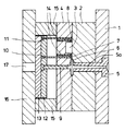
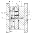
図1は本発明の実施の形態1における成形金型の断面図、図2は成形品の離型状態を示す断面図、図3は成形品の斜視図である。この実施の形態では、成形品として、プラスチックプリズムを成形するものである。
(Embodiment 1)
FIG. 1 is a cross-sectional view of a molding die according to
図1に示す成形金型において、固定側取付板1及び固定側型板2によって固定側金型が構成されている。また、固定側型板2と可動側型板4とが対向することにより、成形用のキャビティ3が形成される。
In the molding die shown in FIG. 1, the stationary side mold is constituted by the stationary
固定側取付板1及び固定側型板2を連通して配置されたスプルブッシュ5のスプル5aと、固定側型板2と可動側型板4とに設けたランナ6と、ゲート7とによって樹脂流路が形成され、キャビティ3の側方には、オーバーフロー8が形成される。これらのスプル5a、ランナ6、ゲート7、キャビティ3及びオーバーフロー8によって樹脂充填空間が構成される。
Resin is formed by the sprue 5a of the
コールドスラグ用突き出しピン9、ゲート用突き出しピン10、オーバーフロー用突き出しピン11は、成形品18の離型方向に平行に延びており、それぞれが成形品を突き出するエジェクタピンとして機能する。これらの各ピンの基端側は、上側突出板12及び下側突出板13によって把持され、且つ可動側型板4内を摺動可能となっている。
The cold
可動側型板4には、さらに離型用ガイドピン14が圧入によって固定されている。離型用ガイドピン14は、離型用ガイド部材となるものであり、可動側型板4に圧入された状態でゲート7及びオーバーフロー8の空間内に突き出ている。すなわち、この実施の形態では、離型用ガイドピン14は樹脂流路におけるキャビティ3の前(ゲート7)及び後(オーバーフロー8)に配置されるものである。
Further, a
離型用ガイドピン14は、上述したエジェクタピン9,10,11と同様に、成形品28の離型方向と平行となるように延びており、ストレートピンが使用されている。ストレートピンを使用することにより、離型用ガイドピン14を簡単な構造とすることができると共に、離型の際に成形品が円滑に離型用ガイドピン14に沿って移動することができ、離型を円滑に行うことができる。
Similar to the
また、離型用ガイドピン14はゲート7及びオーバーフロー8に突き出ることにより、これらの樹脂充填空間を横切っていると共に、離型用ガイドピン14が突き出た空間が樹脂充填空間となっている。従って、離型用ガイドピン14は、樹脂充填空間の一部を形成する部材として機能している。
Further, the
可動側型板4はスペーサブロック15を介して可動側取付板16に固定されている。可動側取付板16には、図示略した成形機の突き出しロッドが通過するためのロッド通過穴17が設けられており、上側突出板12、下側突出板13を突き出するようになっている。この実施の形態において、可動側型板4、スペーサブロック15及び可動側取付板16は、成形品の離型の際の型開き動作時に一体となって固定側金型に対し移動する可動側金型を構成する。
The movable
図1においては、離型用ガイドピン14が固定側型板2に接触して、可動側型板4と同一な面となっているが、固定側型板2との間に隙間があっても良い。
In FIG. 1, the
このようなプラスチック成形金型に樹脂を充填することにより成形された成形品18は、図2に示すように、樹脂充填空間に対応したゲート部19、オーバーフロー部20、製品部21及びスプルランナ部22によって構成される。オーバーフロー部20及びゲート部19には、離型用ガイドピン14のピン跡20a、19aが形成されるが、製品部21とは無関係となっている。
As shown in FIG. 2, the molded
以上のような構造のプラスチック成形金型に対して成形工程を開始する。図1のように金型を閉じた状態で、図示を省略した成形機の可塑化装置から溶融樹脂が射出される。射出された樹脂は、スプルブッシュ5のスプル5a、ランナ6を通り、ゲート7、キャビティ3、オーバーフロー8の順で樹脂充填空間に充填される。その後、保圧、冷却工程を経た後、成形機の型開き動作により固定側型板2と可動側型板4との間が開く。
A molding process is started for the plastic mold having the above structure. With the mold closed as shown in FIG. 1, molten resin is injected from a plasticizer of a molding machine (not shown). The injected resin passes through the sprue 5a of the
次に、図示を省略した成形機の突き出しロッドが、可動側取付板16のロッド通過穴17を通り、下側突出板13に接触し更に前進する。これによりコールドスラグ用突き出しピン9、ゲート用突き出しピン10、オーバーフロー用突き出しピン11が成形品18のスプルランナ部22、ゲート部19、オーバーフロー部20を突き出して可動側型板4から成形品18を離型させる。
Next, the protruding rod of the molding machine (not shown) passes through the
この離型の際には、成形品18のゲート部19及びオーバーフロー部20は、離型用ガイドピン14に沿って摺動する。従って、ゲート部19及びオーバーフロー部20のモーメント力が抑えられた状態で成形品18が可動側型板4から離型される。これによりゲート部19と製品部21の繋ぎ目及びオーバーフロー部20と製品部21の繋ぎ目には、変形、割れ、ひび、白化等が発生することがない。また、離型用ガイドピン14に沿って離型されるため、離型バランスが良い状態で離型することができる。これらにより、要求性能を満足した製品部21を有する成形品18を離型することができる。
During the mold release, the
離型の後には、ゲート部19、オーバーフロー部20を製品部21から切り離して製品とする。
After the mold release, the
(実施の形態2)
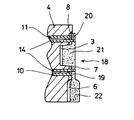
図4は本発明の実施の形態2におけるプラスチック成形金型の断面図、図5は成形品の離型状態を示す断面図である。
(Embodiment 2)
FIG. 4 is a cross-sectional view of a plastic mold according to
この実施の形態では、図4に示すように、離型用ガイドピン31が可動側取付板16に圧入されることにより固定されている。離型用ガイドピン31は離型用ガイド部材となるものであり、離型方向と平行となるように延びている。この離型用ガイドピン31は下側突出板13、上側突出板12、可動側型板4を貫通し、樹脂充填空間の一部であるゲート7並びにオーバーフロー8に突き出ている。
In this embodiment, as shown in FIG. 4, the
この離型用ガイドピン31の外周には、突き出しスリーブ32が設けられている。突き出しスリーブ32は、軸方向に貫通穴が形成されており、離型用ガイドピン31がこの貫通穴内に挿入されている。突き出しスリーブ32は、成形品を突き出すエジェクタピンとして機能するものであり、その先端はゲート7、オーバーフロー8の一部を構成している。この突き出しスリーブ32の基端側の鍔部32aは上側突出板12及び下側突出板13の間に把持されており、可動側型板4に対して摺動可能となっている。
A protruding
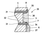
このようなプラスチック成形金型に樹脂を充填することにより成形された成形品33は、図5に示すように、樹脂充填空間に対応したゲート部34、オーバーフロー部35、製品部36及びスプルランナ部37によって構成されている。
As shown in FIG. 5, the molded
この実施の形態では、成形金型の内部に充填された樹脂の冷却が終了し、成形機の型開き動作により固定側型板2と可動側型板4の間が開く。その後、図示を省略した成形機の突き出しロッドが、可動側型板16に設けたロッド通過穴17を通り、下側突出板13に接触し更に前進する。これによりコールドスラグ用突き出しピン9、突き出しスリーブ32が成形品33を可動側型板4から離型させる。
In this embodiment, the cooling of the resin filled in the molding die is finished, and the fixed
この離型の際には、成形品33のゲート部34及びオーバーフロー部35は、離型用ガイドピン31に沿って摺動するため、ゲート部34及びオーバーフロー部35のモーメント力が抑えられた状態で成形品33が可動側型板4から離型される。これによりゲート部34と製品部36の繋ぎ目及びオーバーフロー部35と製品部36の繋ぎ目には、変形、割れ、ひび、白化等が発生することがないと共に、バランス良く離型することができる。従って、要求性能を満足した製品部36を有する成形品33を離型することができる。
At the time of the mold release, the
離型の後には、ゲート部34、オーバーフロー部35を製品部36から切り離して製品とする。
このような実施の形態では、突き出しスリーブ32の内部を離型用ガイドピン31が通るように配置しているため、離型用ガイドピン31を設けるためのスペースが必要なく、これにより、成形品の機能有効範囲外のスペースを小さくすることができる。
After the mold release, the
In such an embodiment, since the
(実施の形態3)
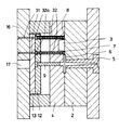
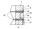
図6は本発明の実施の形態3におけるプラスチック成形金型の断面図、図7は成形品の離型状態を示す断面図である。
(Embodiment 3)
FIG. 6 is a cross-sectional view of a plastic mold according to
この実施の形態では、図6に示すように、離型用ガイドスリーブ41が可動側型板4に圧入されることにより固定されている。離型用ガイドスリーブ41は離型用ガイド部材となるものであり、離型方向と平行となるように延びている。
In this embodiment, as shown in FIG. 6, the
離型用ガイドスリーブ41の先端は、ゲート7並びにオーバーフロー8の空間に突き出し、且つ固定側型板2との間に隙間を設け、この隙間に樹脂が流入するようになっている。従って、離型用ガイドスリーブ41の先端及び先端の外周面はゲート7とオーバーフロー8の樹脂充填空間の一部を形成する部材として機能する。
The tip of the
離型用ガイドスリーブ41は中空状となっており、その内部には、エジェクタピンとしての突き出しピン42が軸方向に挿入されている。突き出しピン42は、その先端が離型用ガイドスリーブ41の先端よりも低くなっていて(すなわち、突き出しピン42が離型用ガイドスリーブ41の先端よりも引っ込んでいて)、離型用ガイドスリーブ41には、先端に対して樹脂が流入するようになっている。従って、離型用ガイドスリーブ41は、その先端がゲート7及びオーバーフロー8の一部を構成し、金型壁面の一部となっている。突き出しピン42の基端側の鍔部42aは上側突出板12及び下側突出板13の間に把持されており、可動側型板4に対して摺動可能となっている。
The
このようなプラスチック成形金型に樹脂を充填することにより成形された成形品43は、図7に示すように、樹脂充填空間に対応したゲート部44、オーバーフロー部45、製品部46及びスプルランナ部47によって構成されている。
As shown in FIG. 7, a molded
この実施の形態においても、成形金型の内部に充填された樹脂の冷却が終了し、成形機の型開き動作により固定側型板2と可動側型板4の間が開く。その後、図示を省略した成形機の突き出しロッドが、可動側取付板16に設けたロッド通過穴17を通り、下側突出板13に接触し更に前進する。これによりコールドスラグ用突き出しピン9、突き出しピン42が成形品43を可動側型板4から離型させる。
Also in this embodiment, the cooling of the resin filled in the molding die is finished, and the fixed
この離型の際には、成形品43のゲート部44及びオーバーフロー部45は、離型用ガイドスリーブ41に沿って摺動するため、ゲート部44及びオーバーフロー部45のモーメント力が抑えられた状態で成形品43が可動側型板4から離型される。これによりゲート部44と製品部46の繋ぎ目及びオーバーフロー部45と製品部46の繋ぎ目には、変形、割れ、ひび、白化等が発生することがないと共に、離型バランスが良好となる。従って、要求性能を満足した製品部46を有する成形品43を離型することができる。
At the time of the mold release, the gate portion 44 and the
離型の後には、ゲート部44、オーバーフロー部45を製品部46から切り離して製品とする。
After the mold release, the gate part 44 and the
このような実施の形態においても、離型用ガイドスリーブ41が突き出しピン42の外周側に設けられているため、離型用ガイドスリーブ41を設けるためのスペースが必要なく、成形品の機能有効範囲外のスペースを小さくすることができる。特に、この実施の形態では、実施の形態2に比べて、成形品の離型をガイドする離型用ガイドスリーブ41を太く短くすることができると共に可動側型板4に圧入して固定するために剛性を増大することができる。このため、より小さなモーメント力により離型変形が発生する成形品に対しても有効な効果を有するものとなっている。
Also in such an embodiment, since the
(実施の形態4)
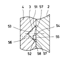
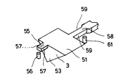
図8は本発明の実施の形態4におけるキャビティの断面図であり、オーバーフロー8をキャビティ3の内部から見た断面を示し、図9はキャビティ3の形状を示す斜視図である。
(Embodiment 4)
FIG. 8 is a cross-sectional view of the cavity according to the fourth embodiment of the present invention, showing a cross section of the
この実施の形態では、キャビティ3は固定側型板2の第1キャビティ面51と、可動側型板4の第2キャビティ面52及び第3キャビティ面53によって形成されている。また、オーバーフロー55はキャビティ3の中心位置(一点鎖線で示した位置)54より著しく下側にずれて形成されおり、エジェクタピンとして機能するオーバーフロー突き出しピン56が対向するように配置されている。このオーバーフロー55の図8紙面奥行き方向に延びる両側面のガイド面57は可動側型板4からの離型方向に対して平行となっている。
In this embodiment, the
さらに、キャビティ3に樹脂を注入するための樹脂流路であるゲート58(図9参照)も、オーバーフロー55と同様に、図8の紙面奥行き方向に延び、且つ離型方向に対して平行な両側面のがイド面59を有している。このゲート58には、成形品を突き出するためのエジェクタピン61が対向するように配置されている。図8において、符号58は、固定側型板2と可動側型板4によって構成されるパーティング面である。
Further, the gate 58 (see FIG. 9), which is a resin flow path for injecting resin into the
この実施の形態において、成形金型内部に注入された樹脂の冷却が終了し、成形機の型開き動作により固定側型板2と可動側型板4の間が開く。その後、図示を省略した成形機の突き出しロッドが作動して離型が開始される。このとき、オーバーフロー55に配置したオーバーフロー突き出しピン56が成形品を突き出すことにより、キャビティ3内で成形された成形品には、図8の紙面に垂直に立てた軸に対して反時計回りのモーメント力、すなわちあおりが発生する。しかしながら、オーバーフロー55に設けた両側面のガイド面57により成形品が回転することなく離型が行われるため、第3キャビティ面53が転写して成形された成形品の端部が、離型後のあおりによって可動側型板2のパーティング面58に接触することがなく、接触に起因した傷が発生することがない。
In this embodiment, the cooling of the resin injected into the molding die is completed, and the fixed
従って、この実施の形態においても、要求性能を満足した製品部を有する成形品を離型することができる。 Therefore, also in this embodiment, a molded product having a product portion that satisfies the required performance can be released.
以上の実施の形態1〜3では、離型用ガイド部材14,31,41をゲート7及びオーバーフロー8の双方に配置しているが、本発明では、これらの内のいずれか一方に配置することにより同様な効果を得ることができる。また、このことは、実施の形態4においても同様であり、ガイド面57,59のいずれか一方を設けることにより同様な効果を得ることが可能となる。
In the above first to third embodiments, the
1 固定側取付板
2 固定側型板
3 キャビティ
5 スプルブッシュ
5a スプル
6 ランナ
7,58 ゲート
8,55 オーバーフロー
14,31 離型用ガイドピン
41 離型用ガイドスリーブ
57,59 ガイド面
DESCRIPTION OF
Claims (7)
前記成形品を離型する離型方向と平行な離型用ガイド部材が、樹脂流路におけるキャビティの前及び後の少なくとも一方の樹脂充填空間を横切るように可動側金型に取り付けられていることを特徴とするプラスチック成形金型。 A plastic mold that molds the molded product by injecting resin into the sprue, runner, gate, cavity, and overflow of the resin-filled space formed by the fixed-side mold and the movable-side mold. In
A release guide member parallel to the release direction for releasing the molded product is attached to the movable mold so as to cross at least one resin filling space before and after the cavity in the resin flow path. Plastic molding mold characterized by
成形品の離型方向と平行な離型用ガイド部材を樹脂流路におけるキャビティの前及び後の少なくとも一方の樹脂充填空間を横切るように可動側金型に設け、成形品を離型用ガイド部材に沿って離型させることを特徴とするプラスチック成形方法。 In a plastic molding method in which a molded product molded by injecting resin is released by an ejector pin against sprues, runners, gates, cavities and overflows in a resin-filled space formed by a fixed mold and a movable mold. ,
A mold release guide member parallel to the mold release direction of the molded product is provided in the movable mold so as to cross at least one of the resin filling spaces before and after the cavity in the resin flow path, and the molded product is provided with the mold release guide member. A plastic molding method characterized in that the mold is released along the line.
樹脂流路におけるキャビティの前及び後の少なくとも一方の樹脂充填空間の内面に、前記成形品を離型する方向と平行であって成形品離型の際のガイドとなるガイド面が両側面となるように形成されていることを特徴とするプラスチック成型金型。 A plastic mold that molds the molded product by injecting resin into the sprue, runner, gate, cavity, and overflow of the resin-filled space formed by the fixed-side mold and the movable-side mold. In
Guide surfaces that are parallel to the direction of releasing the molded product and serve as guides for releasing the molded product are both side surfaces on the inner surface of at least one of the resin filling spaces before and after the cavity in the resin flow path. A plastic molding die characterized by being formed as follows.
Priority Applications (1)
| Application Number | Priority Date | Filing Date | Title |
|---|---|---|---|
| JP2004119842A JP2005297466A (en) | 2004-04-15 | 2004-04-15 | Plastic mold and plastic molding method |
Applications Claiming Priority (1)
| Application Number | Priority Date | Filing Date | Title |
|---|---|---|---|
| JP2004119842A JP2005297466A (en) | 2004-04-15 | 2004-04-15 | Plastic mold and plastic molding method |
Publications (1)
| Publication Number | Publication Date |
|---|---|
| JP2005297466A true JP2005297466A (en) | 2005-10-27 |
Family
ID=35329590
Family Applications (1)
| Application Number | Title | Priority Date | Filing Date |
|---|---|---|---|
| JP2004119842A Withdrawn JP2005297466A (en) | 2004-04-15 | 2004-04-15 | Plastic mold and plastic molding method |
Country Status (1)
| Country | Link |
|---|---|
| JP (1) | JP2005297466A (en) |
Cited By (3)
| Publication number | Priority date | Publication date | Assignee | Title |
|---|---|---|---|---|
| WO2008102468A1 (en) * | 2007-02-20 | 2008-08-28 | Tohshin Seiko Co., Ltd. | Process for producing molded item of thermosetting resin and injection molding machine therefor |
| JP2008238701A (en) * | 2007-03-28 | 2008-10-09 | Toshin Seiko:Kk | Mold, liquid resin injection molding method, and optical element |
| JP2010221691A (en) * | 2009-02-25 | 2010-10-07 | Fuji Xerox Manufacturing Co Ltd | Mold for long molded article and method for manufacturing long molded article |
-
2004
- 2004-04-15 JP JP2004119842A patent/JP2005297466A/en not_active Withdrawn
Cited By (3)
| Publication number | Priority date | Publication date | Assignee | Title |
|---|---|---|---|---|
| WO2008102468A1 (en) * | 2007-02-20 | 2008-08-28 | Tohshin Seiko Co., Ltd. | Process for producing molded item of thermosetting resin and injection molding machine therefor |
| JP2008238701A (en) * | 2007-03-28 | 2008-10-09 | Toshin Seiko:Kk | Mold, liquid resin injection molding method, and optical element |
| JP2010221691A (en) * | 2009-02-25 | 2010-10-07 | Fuji Xerox Manufacturing Co Ltd | Mold for long molded article and method for manufacturing long molded article |
Similar Documents
| Publication | Publication Date | Title |
|---|---|---|
| US7837915B2 (en) | Injection molding process, resin molded product and mold | |
| JP2005297466A (en) | Plastic mold and plastic molding method | |
| JP2009292132A (en) | Molding method and mold die for resin molding | |
| JP2009056503A (en) | Molding metal mold and molding method | |
| JP2012223989A (en) | Injection molding method, and die for injection molding | |
| JP2009143051A (en) | Ejection mechanism of injection molding machine | |
| JP5869442B2 (en) | Film insert molding equipment | |
| JP2005007713A (en) | Method for demolding plastic molding and mold | |
| JP6199346B2 (en) | Molding method and injection molding machine characterized by extrusion of molded product | |
| JP2976264B2 (en) | Injection molding method of three-layer structure molded article and its mold | |
| JP4040963B2 (en) | Injection mold | |
| JP2007237665A (en) | Manufacturing method of resin shaped body | |
| JP2003039491A (en) | Mold assembly for injection-molding and injection- molding method using this mold | |
| JP2007223252A (en) | Mold for injection molding of optical element and its molding method | |
| JP2004291324A (en) | Mold for multicolor molding and multicolor molding method | |
| JP2005246770A (en) | Injection mold | |
| JP4275083B2 (en) | Manufacturing method of operation parts for mobile phone and manufacturing apparatus used in the manufacturing method | |
| JP3749878B2 (en) | Deep molding injection molding method and injection molding die | |
| JP3974544B2 (en) | Mold equipment | |
| JP2509868Y2 (en) | Injection mold | |
| JP2001138373A (en) | Injection molding method and injection mold | |
| JP2000271977A (en) | Injection mold | |
| JP6214592B2 (en) | Mold for resin molding | |
| JPH09277014A (en) | Production of light alloy die cast product using resin core and hollow light alloy die cast product | |
| JPH08281715A (en) | Injection mold |
Legal Events
| Date | Code | Title | Description |
|---|---|---|---|
| A300 | Withdrawal of application because of no request for examination |
Free format text: JAPANESE INTERMEDIATE CODE: A300 Effective date: 20070703 |