JP2005297062A - Method and apparatus for manufacturing tube with spiral groove on inside surface - Google Patents
Method and apparatus for manufacturing tube with spiral groove on inside surface Download PDFInfo
- Publication number
- JP2005297062A JP2005297062A JP2005072289A JP2005072289A JP2005297062A JP 2005297062 A JP2005297062 A JP 2005297062A JP 2005072289 A JP2005072289 A JP 2005072289A JP 2005072289 A JP2005072289 A JP 2005072289A JP 2005297062 A JP2005297062 A JP 2005297062A
- Authority
- JP
- Japan
- Prior art keywords
- plug
- spiral
- mandrel
- tube
- extrusion
- Prior art date
- Legal status (The legal status is an assumption and is not a legal conclusion. Google has not performed a legal analysis and makes no representation as to the accuracy of the status listed.)
- Granted
Links
- 238000004519 manufacturing process Methods 0.000 title claims abstract description 25
- 238000000034 method Methods 0.000 title claims abstract description 13
- 238000001125 extrusion Methods 0.000 claims abstract description 52
- 239000007769 metal material Substances 0.000 claims abstract description 8
- 238000003825 pressing Methods 0.000 claims abstract description 6
- 229910000838 Al alloy Inorganic materials 0.000 description 4
- 238000000465 moulding Methods 0.000 description 4
- 238000013459 approach Methods 0.000 description 1
- 238000010586 diagram Methods 0.000 description 1
- 239000000463 material Substances 0.000 description 1
- 238000012805 post-processing Methods 0.000 description 1
- 238000004804 winding Methods 0.000 description 1
Images
Landscapes
- Extrusion Of Metal (AREA)
Abstract
Description
本発明は、内面に螺旋状の溝を有する管を押出成形により製造する方法及びその装置に関する。 The present invention relates to a method and an apparatus for manufacturing a tube having a spiral groove on the inner surface by extrusion.
熱交換器などに使用される伝熱管としては、その伝熱効率を高めるために管の内面に細かい螺旋状の溝を設けたものが採用されている。螺旋状の溝を形成するための方法も各種提案されており、押出直後にダイスにて縮径させると共にマンドレルの先端に設けた溝付プラグとダイスの間から押出して管の内面に溝を形成する方法や(例えば、特許文献1参照)、溝付マンドレルを外部から駆動して回転させ螺旋溝を形成する回転ホイール式押出機による方法や(例えば、特許文献2参照)、ポートホール形状をねじらせることでチャンバー内に旋回流を生成させてマンドレルのねじれ溝に沿って押出す方法(例えば、特許文献3参照)等が開示されている。
しかしながら、押出直後にダイスを縮径させる構造では、押出成形を開始する時の頭出しで詰まって押出不可能になる恐れがあり、仮に押出成形が可能となっても縮径部の抵抗が大きくなり生産性が低下するものであった。また、マンドレル先端のプラグを外部駆動手段により回転させる方法は、回転ホイール式押出では適用が可能であるが、一般的な直接押出の場合にはプラグの駆動軸上に押出機のステムが存在するためプラグの駆動ができず、適用が困難であった。 However, in the structure in which the diameter of the die is reduced immediately after extrusion, cueing at the start of extrusion molding may cause clogging and extrusion may become impossible, and even if extrusion molding is possible, the resistance of the reduced diameter portion is large. As a result, productivity was lowered. Further, the method of rotating the plug at the tip of the mandrel by the external drive means can be applied in the rotary wheel type extrusion, but in the case of general direct extrusion, the stem of the extruder exists on the drive shaft of the plug. Therefore, the plug could not be driven and was difficult to apply.
また、材料を大きくねじらせてから押出す方法では、押出管の外周が大きく回転されて押し出されるため押出管の先端をチャックし押出方向に先導するプラーを回転可能な構造にする必要があるが、一般的に熱交換チューブは後加工工程の都合や生産性を確保するため連続的に押出成形された後にコイルに巻いた状態にする場合が多く、回転するプラーとコイル巻き取り装置を両立させるには極めて複雑な設備が必要であった。 Further, in the method of extruding after twisting the material largely, the outer periphery of the extruded tube is greatly rotated and pushed out, so the tip of the extruded tube needs to be chucked and the puller leading in the extrusion direction needs to be structured to be rotatable. However, in general, heat exchange tubes are often continuously extruded and wound in a coil to ensure the convenience of post-processing and productivity, and both a rotating puller and a coil winding device are compatible. To do so, extremely complicated equipment was required.
それゆえ、本発明は、上記の事情を背景になされたものであり、生産性の低下をできるだけ抑えつつ、内面に螺旋状の溝を有する管を複雑な機構を用いず容易に製造する方法及びその装置を提供することを技術的課題とする。 Therefore, the present invention has been made in the background of the above circumstances, and a method for easily manufacturing a pipe having a spiral groove on the inner surface without using a complicated mechanism while suppressing a decrease in productivity as much as possible. It is a technical problem to provide such a device.
上記した技術的課題を解決するため、本発明は、請求項1に記載のように、金属材料の押出成形により内面螺旋溝付管を製造する方法において、外周に複数の螺旋状の突部を有するプラグをマンドレルよりも押出方向前方に設け、前記プラグの最大外接円の直径を前記マンドレルの外径より大きく設定し、金属材料をダイスと前記マンドレルの間から押し出して押出管を形成し、該押出管を前記プラグに押し付けて内面に螺旋溝を形成することを特徴とする内面螺旋溝付管の製造方法とした。
In order to solve the above technical problem, the present invention provides a method of manufacturing an internally spiral grooved tube by extrusion molding of a metal material as described in
本発明に係る内面螺旋溝付管の製造方法によれば、一般的な押出装置のマンドレルの先端に螺旋状の突部を有するプラグを設けるだけで、管の内面に螺旋溝を形成することができる。また、金属材料をダイスとマンドレルの間から押し出して押出管を形成した後に、マンドレルにより内径が成形されたその押出管をプラグに押し付けるので、プラグの外周部で金属材料がダイス等によって外面を拘束されずに内面に螺旋溝を形成することができる。従って、螺旋溝の形成がスムーズに行われるので、生産性を向上させることが可能となる。 According to the method for manufacturing an internally spiral grooved tube according to the present invention, a spiral groove can be formed on the inner surface of a tube simply by providing a plug having a spiral protrusion at the tip of a mandrel of a general extrusion device. it can. In addition, after extruding a metal material from between the die and the mandrel to form an extruded tube, the extruded tube having an inner diameter formed by the mandrel is pressed against the plug, so that the outer surface of the plug restrains the outer surface with a die or the like. Instead, a spiral groove can be formed on the inner surface. Accordingly, since the spiral groove can be formed smoothly, productivity can be improved.
好ましくは、請求項2に記載のように、プラグは、押出方向前方に向って拡径した形状であることが望ましい。このように、プラグをテーパ状にすることで、ダイスとマンドレルの間から押し出して形成した押出管の内面に、プラグのねじれ形状の突部が徐々に押し付けられるので、管の内面に螺旋溝が形成され易くなる。また、請求項3に記載のように、プラグは回転自在にして、押出管をプラグに押し付けてプラグを回転させながら内面に螺旋溝を形成することが望ましい。これにより、摩擦抵抗が減ることによって管の内面への螺旋溝の形成がより容易になるとともに、成形時の内面螺旋溝付管のねじれやうねりを抑えることができる。
Preferably, as described in
より好ましくは、請求項4に記載のように、マンドレルのポート孔は、プラグの螺旋状の突部と同じねじれ方向又は反対のねじれ方向にねじらせて形成した形状であることが望ましい。これにより、ダイスとマンドレルの間から押出管がプラグの回転方向とは反対方向又は同じ方向に回転されて押し出されるので、プラグの螺旋状突起により発生する回転力と、プラグが押出方向に押し付けられることにより発生する回転抵抗とのバランスにおいて、最適な状態とすることが可能となり、より大きなねじれ角度の螺旋溝を有する内面螺旋溝付管を製造することが可能となる。
More preferably, as described in
また本発明は、請求項5に記載のように、外周に複数の螺旋状の突部を有するプラグを用いて内面螺旋溝付管を押出成形する製造装置であって、前記プラグを押出方向前方に向って拡径した形状にしたことを特徴とする内面螺旋溝付管の製造装置とした。このようなプラグを使用することで、ダイスとマンドレルの間から押し出して形成した押出管の内面に、プラグのねじれ形状の突部が徐々に押し付けられるので、管の内面に螺旋溝が形成され易くなり、製造装置の生産性を向上させることが可能となる。 According to a fifth aspect of the present invention, there is provided a manufacturing apparatus for extruding an internally spiral grooved tube using a plug having a plurality of spiral protrusions on an outer periphery thereof, wherein the plug is disposed forward of the extrusion direction. It was set as the manufacturing apparatus of the pipe | tube with an internal spiral groove characterized by making it the shape expanded toward the direction. By using such a plug, the twisted protrusion of the plug is gradually pressed against the inner surface of the extruded tube formed by extruding from between the die and the mandrel, so that a spiral groove is easily formed on the inner surface of the tube. Thus, the productivity of the manufacturing apparatus can be improved.
好ましくは、請求項6に記載のように、プラグをマンドレル及びダイスよりも押出方向前方に設けるとともに、プラグの最大外接円の直径をマンドレルの外径より大きく設定することが望ましい。これによれば、一般的な押出装置においてマンドレルの先端に螺旋状の突部を有するプラグを設けるだけで、管の内面に螺旋溝を形成した内面螺旋溝付管を製造する装置とすることができる。
Preferably, as described in
本発明によれば、外周に複数の螺旋状の突部を有するプラグを用いてスムーズに管の内面に螺旋溝を形成することができるので、生産性の低下を抑えつつ、容易に内面螺旋溝付管を製造することが可能となる。 According to the present invention, since the spiral groove can be smoothly formed on the inner surface of the pipe using the plug having a plurality of spiral protrusions on the outer periphery, the inner surface spiral groove is easily suppressed while suppressing the reduction in productivity. It becomes possible to manufacture a tube.
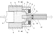
以下、本発明の実施の形態を、図面を用いて説明する。図1は、本発明の一実施形態を模式的に示した断面図である。図1に示すように、マンドレル(ダイマンドレル)1にはダイス(ダイキャップ)2が組み合わされ、断面孔を形成している。マンドレル1とダイス2は、前方のバッカー7と共にダイリング8に組み付けられて、押出型を構成している。加熱された金属材料であるビレット5を、コンテナヒーター6により加熱されたコンテナ3に挿入し、ステム4により押出型に押し付けることで、押出型の断面孔から押出管11が押出成形可能となっている。
Hereinafter, embodiments of the present invention will be described with reference to the drawings. FIG. 1 is a cross-sectional view schematically showing an embodiment of the present invention. As shown in FIG. 1, a mandrel (die mandrel) 1 is combined with a die (die cap) 2 to form a cross-sectional hole. The
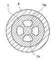
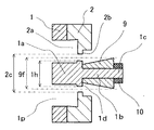
図2は図1のA−A断面図、図3はマンドレル1とダイス2を主とした図1の部分拡大断面図である。図2に示すように、マンドレル1には、押出方向に平行な4つのポート孔1pが形成されている。マンドレル1の中心に位置するオス首部1aは、押出管11の内面を成形するベアリング1dを有している。ダイス2は、押出管11の外面を成形するベアリング2bを有している。ベアリング1dとベアリング2bは、押出方向において略同じ位置となっており、押出型の断面孔を形成している。
2 is a cross-sectional view taken along line AA of FIG. 1, and FIG. 3 is a partially enlarged cross-sectional view of FIG. 1 mainly including a
マンドレル1のオス首部1aの先端には、シャフト1bが設けられ、このシャフト1bにプラグ9が回転自在に取り付けられている。シャフト1bの先端にはネジ部1cが形成され、プラグ9の抜け止め用のナット10が取り付けられている。シャフト1bの先端にネジ孔を形成してナット10の代わりにボルトを用いてプラグ9の抜け止めとしたり、別体のシャフト1bをオス首部1aに組み付けるようにしたりしてもよい。
A
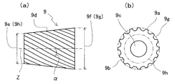
図4はプラグ9単体を示す図であり、図4(a)は正面図、図4(b)は右側面図である。プラグ9は、外周に複数の螺旋状の突部9aを有している。突部9aは、押出方向に対して所定のねじれ角αで右回転方向に旋回して形成されている。隣あう2つの突部9aの間には、同様に右回転方向に旋回した螺旋状の凹部9bが形成されている。ねじれ角αは、図4(a)に示すように正面(押出軸Zと垂直な方向)から見て、突部9aが押出軸Zとなす角度である。
4A and 4B are diagrams showing the
プラグ9は、押出方向前方に向って拡径した形状に形成されている。すなわち、プラグ9の後端の外接円9hから前端の外接円9gに向って徐々に径が大きくなっており、図4(a)に示すような正面視では、押出方向に広がるテーパ部9dとなっている。
The
プラグ9のプラグ孔9cにシャフト1bを挿入して、プラグ9がマンドレル1に組み付けられる。図3に示すように、プラグ9の最大の突起径である前端の外接円9gの直径9fは、マンドレル1のベアリング1dの外径1hより大きく、かつ、ダイス2のベアリング2bの内径2cより小さく設定されている。プラグ9の最小の突起径である後端の外接円9hの直径9eは、マンドレル1のベアリング1dの外径1hより小さく設定されている。
The
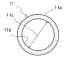
図1に示すように、加熱されたアルミニウム合金のビレット5を、コンテナヒーター6により加熱されたコンテナ3に挿入し、ステム4により押出型に押し付けることで、アルミニウム合金がポート孔1p及びチャンバー2aを経由し、ベアリング1dとベアリング2bの間から押出管11が押出成形される。この押出管11は、図5に示すような断面となり、押出管11の外面11aの外径はベアリング2bの内径2cと略同一であり、押出管11の内面11bの内径はベアリング1dの外径1hと略同一である。押出管11は、平滑な円柱パイプであり、ベアリング1dとベアリング2bの間から押し出された直後であるので、外面11a及び内面11bには凹凸が無い。
As shown in FIG. 1, a billet 5 of a heated aluminum alloy is inserted into a container 3 heated by a
プラグ9の後端の外接円9hの直径9eが押出管11の内径11cより小さいため、押出型から押し出された直後の押出管11は、プラグ9の突部9aに接触しない。その後、プラグ9の突部9aの外接円が押出方向前方に向って拡大するに伴って、押出管11の内面11bは、徐々に突部9aに近づき、やがて突部9aに接触し、徐々に突部9aに押し付けられる。その結果、押出管11の内径11cに、螺旋溝12cが成形される。プラグ9は、押出管11の内径11cへの溝成形時の抵抗により、シャフト1bを中心に左回転する。
Since the
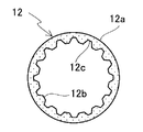
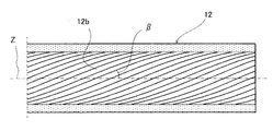
プラグ9が左回転することで、押出管11の内径11cに形成される螺旋溝12cは、押出方向に対して所定のねじれ角βで右回転方向に旋回して形成され、スパイラルチューブである内面螺旋溝付管12が製造される。内面螺旋溝付管12は、図6に示すような断面となり、外面12aは平滑で凹凸が無く、内面12bに螺旋溝12cが形成されている。ねじれ角βは、図7に示すように横断面図を押出軸Zと垂直な方向から見て、螺旋溝12cが押出軸Zとなす角度である。ねじれ角βは、ねじれ角αよりも小さくなる。
When the
以上のように、本発明に係る内面螺旋溝付管12の製造方法によれば、一般的な押出装置のマンドレル1の先端に螺旋状の突部9aを有するプラグ9を設けるだけで、マンドレル1とダイス2との間から押し出された押出管11の内面11bに螺旋溝12cを形成することができる。また、アルミニウム合金を押し出して押出管11を形成した後に、マンドレル1により内径11bが成形されたその押出管11をプラグ9に押し付けるので、プラグ9の外周部で押出管11がダイス等によって外面11aを拘束されずに内面11bに螺旋溝12cを形成することができる。従って、螺旋溝12cの形成がスムーズに行われるので、生産性を向上させることが可能となる。
As described above, according to the method for manufacturing the inner surface spiral grooved
また、プラグ9を、押出方向前方に向って拡径した形状とし、プラグ9をテーパ状にすることで、ダイス2とマンドレル1の間から押し出して形成した押出管11の内面11bに、プラグ9のねじれ形状の突部9aが徐々に押し付けられるので、押出管11の内面11bに螺旋溝12cが形成され易くなる。また、プラグ9を回転自在にして、押出管11をプラグ9に押し付けてプラグ9を回転させながら内面11bに螺旋溝12cを形成することにより、摩擦抵抗が減ることによって押出管11の内面11bへの螺旋溝12cの形成がより容易になるとともに、成形時の内面螺旋溝付管12のねじれやうねりを抑えることができる。
Further, the
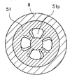
次に、本発明の他の実施形態を説明する。図8は、第2実施形態を示した断面図であり、前述した第1実施形態の図2(図1のA−A断面図)に対応する。尚、本第2実施形態は、図8に示すマンドレル51以外については前述した第1実施形態と同じ構成であり、詳細な説明は省略する。
Next, another embodiment of the present invention will be described. FIG. 8 is a cross-sectional view showing the second embodiment, and corresponds to FIG. 2 (A-A cross-sectional view of FIG. 1) of the first embodiment described above. In addition, this 2nd Embodiment is the same structure as 1st Embodiment mentioned above except the
第2実施形態における第1実施形態との相違点は、マンドレル51のポート孔51pが、押出方向に対してねじらせて形成されている。図8に示す例は、マンドレル51のポート孔51pが、押出方向に対して右回転方向にねじらせて形成されている。すなわち、ポート孔51pは、プラグ9の螺旋状の突部9aと同じねじれ方向にねじらせて形成してある。押出軸Zに対するこのポート孔51pのねじれ角θpは、ダイス2とマンドレル51の間から押し出される押出管11が、若干の回転力が付与される程度とした。ポートねじれ角θpは、プラグねじれ角αと同様に、正面(押出軸Zと垂直な方向)から見て、ポート孔51pが押出軸Zとなす角度である。
The difference of the second embodiment from the first embodiment is that the
ポート孔51pのねじれ角θpは、プラグ9の螺旋状突起9aにより発生する回転力と、プラグ9が押出方向に押し付けられることにより発生する回転抵抗とのバランスにおいて、最適な状態となるように設定されればよい。従って、マンドレル51のポート孔51pが、押出方向に対して左回転方向にねじらせて形成されてもよい。すなわち、ポート孔51pは、プラグ9の螺旋状の突部9aと反対のねじれ方向(図8に示す例と反対のねじれ方向)にねじらせて形成してもよい。表1に、ポート孔51pのねじれ角θpを6水準、プラグ9のねじれ角度αを3水準とし、それぞれ同じ製造条件(ビレット温度400℃、ラム速度1mm/秒)で形成された内面螺旋溝付管の溝ねじれ角度β2示す。
The twist angle θp of the
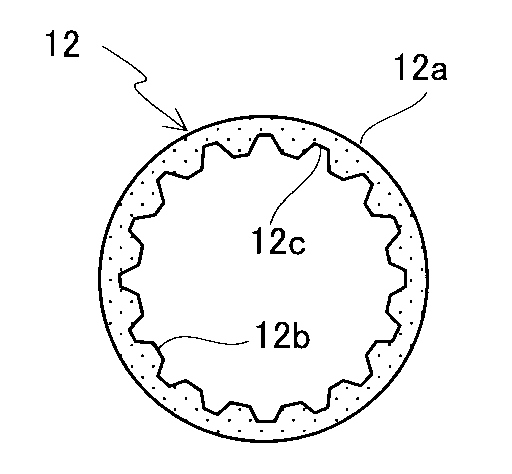
表1に示すように、プラグねじれ角度αが14°の場合は、ポートねじれ角θpが右14°や右21°、すなわちプラグねじれ角度αとおなじ右方向のとき、溝ねじれ角度β2が大きくなっている。このとき、ビレット5のアルミニウム合金はポート孔51、チャンバー2aを経由し、ダイス2とマンドレル51の間から押出管11がプラグ9の回転方向とは反対方向に回転されて押し出されるので、その押出管11に対するプラグ9の相対的な回転量が多くなり、より大きなねじれ角度β2の螺旋溝を有する内面螺旋溝付管を製造することが可能となる。従って、第1実施形態と同じ製造条件(ビレット温度や押出速度)とした場合では、「α>β2>β」となる。また、第2実施形態も第1実施形態と同様に主としてプラグ9の回転により螺旋溝12cが形成されるので、成形時の内面螺旋溝付管のねじれやうねりを最小限に抑えることができる。更には、螺旋溝12cが形成されるときの抵抗がプラグ9を回転させるが、このプラグ9の反力により押出管11に左回転方向の回転力が作用し、ポート孔51pのねじれによる押出管11の右回転方向の回転力と中和する方向に働くため、成形時の内面螺旋溝付管のねじれやうねりを更に抑えることが可能である。
As shown in Table 1, when the plug twist angle α is 14 °, the groove twist angle β2 becomes large when the port twist angle θp is 14 ° right or 21 ° right, that is, when the plug twist angle α is the same right direction as the plug twist angle α. ing. At this time, the aluminum alloy of the billet 5 passes through the
プラグねじれ角αが大きいと、プラグ9が押出方向に押し付けられることにより発生する回転抵抗も大きくなるため、例えばプラグねじれ角αが17.5°の場合では、ポートねじれ角θpが0°や右7°で溝ねじれ角β2が大きくなり、プラグ9の螺旋状突起9aにより発生する回転力と、プラグ9が押出方向に押し付けられることにより発生する回転抵抗とのバランスが最適な状態となっている。また、プラグねじれ角αが21°の場合では、更に回転抵抗も大きくなるため、プラグの回転方向と同じである左方向、すなわちポートねじれ角θpが左7°や0°で溝ねじれ角β2が大きくなり、プラグ9の螺旋状突起9aにより発生する回転力と、プラグ9が押出方向に押し付けられることにより発生する回転抵抗とのバランスが最適な状態となっている。
When the plug twist angle α is large, the rotational resistance generated by the
尚、上記した実施形態では、いずれも内面螺旋溝付管12の螺旋溝12cの数(すなわちプラグ9の突部9aの数)が16本の例を示したが、本発明の実施にあたっては、特に熱交換器用のチューブに適用するときは、もっと多くの螺旋溝(例えば外径φ6mmのチューブでは50本ほどの螺旋溝)とすることもできる。
In each of the above-described embodiments, the example in which the number of the
1、51 マンドレル
1h マンドレルの外径
1p、51p ポート孔
2 ダイス
3 コンテナ
4 ステム
5 ビレット(金属材料)
9 プラグ
9a 突部
9b 凹部
9e プラグ9の後端の外接円
9f プラグ9の前端の外接円(最大外接円)
9g 外接円9fの直径
9h 外接円9eの直径
11 押出管
11a 押出管11の外面
11b 押出管11の内面
12 内面螺旋溝付管
12a 内面螺旋溝付管12の外面
12b 内面螺旋溝付管12の内面
12c 螺旋溝
1, 51 Mandrel 1h Mandrel
9
9g Diameter of circumscribed
Claims (6)
6. The inner spiral grooved tube according to claim 5, wherein the plug is provided in front of the mandrel and the die in the extrusion direction, and the diameter of the maximum circumscribed circle of the plug is set larger than the outer diameter of the mandrel. manufacturing device.
Priority Applications (1)
| Application Number | Priority Date | Filing Date | Title |
|---|---|---|---|
| JP2005072289A JP4708820B2 (en) | 2004-03-16 | 2005-03-15 | Manufacturing method and apparatus for internally spiral grooved tube |
Applications Claiming Priority (3)
| Application Number | Priority Date | Filing Date | Title |
|---|---|---|---|
| JP2004075207 | 2004-03-16 | ||
| JP2004075207 | 2004-03-16 | ||
| JP2005072289A JP4708820B2 (en) | 2004-03-16 | 2005-03-15 | Manufacturing method and apparatus for internally spiral grooved tube |
Publications (2)
| Publication Number | Publication Date |
|---|---|
| JP2005297062A true JP2005297062A (en) | 2005-10-27 |
| JP4708820B2 JP4708820B2 (en) | 2011-06-22 |
Family
ID=35329238
Family Applications (1)
| Application Number | Title | Priority Date | Filing Date |
|---|---|---|---|
| JP2005072289A Expired - Lifetime JP4708820B2 (en) | 2004-03-16 | 2005-03-15 | Manufacturing method and apparatus for internally spiral grooved tube |
Country Status (1)
| Country | Link |
|---|---|
| JP (1) | JP4708820B2 (en) |
Cited By (4)
| Publication number | Priority date | Publication date | Assignee | Title |
|---|---|---|---|---|
| KR100982534B1 (en) | 2008-03-26 | 2010-09-16 | 한국생산기술연구원 | Seamless thixoextrusion tube manufacturing method and device thereof |
| KR101287614B1 (en) | 2012-05-08 | 2013-07-19 | (주)휘일 | Extrusion apparatus for spiral rib pipe |
| US8584501B2 (en) | 2008-01-14 | 2013-11-19 | Korea Institute Of Industrial Technology | Forming device for thixoextrusion and method thereof |
| CN106623474A (en) * | 2017-01-17 | 2017-05-10 | 辽源飞跃工模具有限公司 | Extruding die with interior and exterior of pipe provided with spiral fin proximate matter |
Citations (5)
| Publication number | Priority date | Publication date | Assignee | Title |
|---|---|---|---|---|
| JPS63235020A (en) * | 1987-03-24 | 1988-09-30 | Sumitomo Metal Ind Ltd | Manufacture of hot extruded tube |
| JPH01215408A (en) * | 1988-02-23 | 1989-08-29 | Showa Alum Corp | Manufacture of twist formed part used for rotor or the like |
| JPH06297032A (en) * | 1993-04-15 | 1994-10-25 | Ishikawajima Harima Heavy Ind Co Ltd | Method and device for extruding twisted body |
| JPH09295040A (en) * | 1996-05-10 | 1997-11-18 | Hitachi Cable Ltd | Manufacturing method of inner surface processed metal pipe |
| JPH10166033A (en) * | 1996-12-11 | 1998-06-23 | Hitachi Cable Ltd | Manufacturing method of metal tube with internal spiral fins |
-
2005
- 2005-03-15 JP JP2005072289A patent/JP4708820B2/en not_active Expired - Lifetime
Patent Citations (5)
| Publication number | Priority date | Publication date | Assignee | Title |
|---|---|---|---|---|
| JPS63235020A (en) * | 1987-03-24 | 1988-09-30 | Sumitomo Metal Ind Ltd | Manufacture of hot extruded tube |
| JPH01215408A (en) * | 1988-02-23 | 1989-08-29 | Showa Alum Corp | Manufacture of twist formed part used for rotor or the like |
| JPH06297032A (en) * | 1993-04-15 | 1994-10-25 | Ishikawajima Harima Heavy Ind Co Ltd | Method and device for extruding twisted body |
| JPH09295040A (en) * | 1996-05-10 | 1997-11-18 | Hitachi Cable Ltd | Manufacturing method of inner surface processed metal pipe |
| JPH10166033A (en) * | 1996-12-11 | 1998-06-23 | Hitachi Cable Ltd | Manufacturing method of metal tube with internal spiral fins |
Cited By (6)
| Publication number | Priority date | Publication date | Assignee | Title |
|---|---|---|---|---|
| US8584501B2 (en) | 2008-01-14 | 2013-11-19 | Korea Institute Of Industrial Technology | Forming device for thixoextrusion and method thereof |
| US8650927B1 (en) | 2008-01-14 | 2014-02-18 | Korea Institute Of Industrial Technology | Forming device for thixoextrusion and method thereof |
| DE112008003618B4 (en) | 2008-01-14 | 2019-02-21 | Korea Institute Of Industrial Technology | Mold apparatus for thixoextrusion |
| KR100982534B1 (en) | 2008-03-26 | 2010-09-16 | 한국생산기술연구원 | Seamless thixoextrusion tube manufacturing method and device thereof |
| KR101287614B1 (en) | 2012-05-08 | 2013-07-19 | (주)휘일 | Extrusion apparatus for spiral rib pipe |
| CN106623474A (en) * | 2017-01-17 | 2017-05-10 | 辽源飞跃工模具有限公司 | Extruding die with interior and exterior of pipe provided with spiral fin proximate matter |
Also Published As
| Publication number | Publication date |
|---|---|
| JP4708820B2 (en) | 2011-06-22 |
Similar Documents
| Publication | Publication Date | Title |
|---|---|---|
| JP2009220153A (en) | Method of manufacturing tube with spirally grooved inside surface and its device | |
| JP5376763B2 (en) | Heat exchanger tube | |
| US6470723B2 (en) | Apparatus for manufacturing internal grooved tube | |
| JP2012240084A (en) | Pipe material manufacturing device, pipe material manufacturing method, and pipe material | |
| JP4708820B2 (en) | Manufacturing method and apparatus for internally spiral grooved tube | |
| JP5871269B2 (en) | Spiral tube extrusion molding method and spiral tube extrusion molding machine | |
| JP2002361320A (en) | Friction extrusion method and tool used in the method | |
| JP2000202569A (en) | Manufacture of hollow rack shaft | |
| WO2009122620A1 (en) | Method of producing seamless metal tube and punch for use therein | |
| CN1183067A (en) | Chuck having formed jaws | |
| CN116390822A (en) | Threaded nut for ball screw drive and method for producing the threaded nut | |
| JP2017064905A (en) | Groove forming tool | |
| JP5040686B2 (en) | Die for forging and processing method thereof, gear forging device and gear forging method | |
| JP3111896B2 (en) | Method for manufacturing inner surface processed metal pipe | |
| JPH10166085A (en) | Extrusion molding method for inner grooved pipe | |
| JPH10166036A (en) | Method and apparatus for manufacturing inner grooved pipe | |
| JP2013202615A (en) | Tube expanding billet, tube expanding device, and heat exchanger | |
| JPH1110268A (en) | Manufacturing method of outer grooved pipe | |
| EP3615270B1 (en) | Planetary reform roller and method of reforming a vessel cavity | |
| JP2013018042A (en) | Mandrel for manufacturing internal tooth helical gear, internal tooth helical gear manufacturing apparatus, and method of manufacturing internal tooth helical gear | |
| JPH11319934A (en) | Method and apparatus for manufacturing inner grooved pipe | |
| JP4009261B2 (en) | Pipe end structure and pipe end processing method | |
| WO2014119120A1 (en) | Forging device and forging method | |
| JPH06207623A (en) | Steering rod and manufacture thereof | |
| JP2007111740A (en) | Screw shaft forming method and screw shaft of ball screw mechanism |
Legal Events
| Date | Code | Title | Description |
|---|---|---|---|
| A621 | Written request for application examination |
Free format text: JAPANESE INTERMEDIATE CODE: A621 Effective date: 20071218 |
|
| A977 | Report on retrieval |
Free format text: JAPANESE INTERMEDIATE CODE: A971007 Effective date: 20101111 |
|
| A131 | Notification of reasons for refusal |
Free format text: JAPANESE INTERMEDIATE CODE: A131 Effective date: 20101207 |
|
| A521 | Written amendment |
Free format text: JAPANESE INTERMEDIATE CODE: A523 Effective date: 20110112 |
|
| RD02 | Notification of acceptance of power of attorney |
Free format text: JAPANESE INTERMEDIATE CODE: A7422 Effective date: 20110112 |
|
| A01 | Written decision to grant a patent or to grant a registration (utility model) |
Free format text: JAPANESE INTERMEDIATE CODE: A01 Effective date: 20110307 |
|
| A61 | First payment of annual fees (during grant procedure) |
Free format text: JAPANESE INTERMEDIATE CODE: A61 Effective date: 20110317 |