JP2005296907A - Coating film forming device - Google Patents
Coating film forming device Download PDFInfo
- Publication number
- JP2005296907A JP2005296907A JP2004121185A JP2004121185A JP2005296907A JP 2005296907 A JP2005296907 A JP 2005296907A JP 2004121185 A JP2004121185 A JP 2004121185A JP 2004121185 A JP2004121185 A JP 2004121185A JP 2005296907 A JP2005296907 A JP 2005296907A
- Authority
- JP
- Japan
- Prior art keywords
- nozzle
- coating liquid
- coating
- substrate
- resist
- Prior art date
- Legal status (The legal status is an assumption and is not a legal conclusion. Google has not performed a legal analysis and makes no representation as to the accuracy of the status listed.)
- Granted
Links
Images

Landscapes
- Coating Apparatus (AREA)
- Exposure Of Semiconductors, Excluding Electron Or Ion Beam Exposure (AREA)
Abstract
【課題】 膜厚均一性に優れた塗布膜を形成する塗布膜形成装置を提供する。
【解決手段】 レジスト塗布装置(CT)11は、基板Gを載置する載置台51と、レジストノズル52と、第1・第2ノズル昇降機構54a・54bと、第1・第2ノズル昇降機構54a・54bの駆動を制御する第1・第2昇降制御装置55a・55bと、レジストノズル52と第1・第2ノズル昇降機構54a・54bとを一体的にスライドさせるノズルスライド機構56と、基板Gのうねりを検出する変位センサ58a・58bと、変位センサ58a・58bによる測定値に所定時間の遅延操作を行い、その遅延信号を第1・第2昇降制御装置55a・55bに送る第1・第2バッファー装置86a・86bと、第1・第2バッファー装置86a・86bにおける遅延時間を決定する遅延時間生成装置87と、を有する。基板Gのうねりに対応させてレジストノズル52の昇降および姿勢の制御を行う。
【選択図】 図1
PROBLEM TO BE SOLVED: To provide a coating film forming apparatus for forming a coating film having excellent film thickness uniformity.
A resist coating apparatus (CT) 11 includes a mounting table 51 on which a substrate G is mounted, a resist nozzle 52, first and second nozzle lifting mechanisms 54a and 54b, and first and second nozzle lifting mechanisms. First and second lifting control devices 55a and 55b for controlling driving of 54a and 54b, a nozzle slide mechanism 56 for integrally sliding the registration nozzle 52 and the first and second nozzle lifting mechanisms 54a and 54b, and a substrate The first and second displacement sensors 58a and 58b for detecting the undulation of G, a delay operation for a predetermined time on the measured values by the displacement sensors 58a and 58b, and the first and second lift control devices 55a and 55b for sending the delay signals. The second buffer devices 86a and 86b and the delay time generation device 87 for determining the delay time in the first and second buffer devices 86a and 86b. The raising and lowering of the resist nozzle 52 and the posture control are performed in response to the undulation of the substrate G.
[Selection] Figure 1
Description
本発明は塗布膜形成装置に関し、より詳しくは、例えば、液晶表示装置(LCD)等のFPD(フラットパネルディスプレイ)に用いられるガラス基板等の基板に所定の塗布液を供給して塗布膜を形成する塗布膜形成装置に関する。 The present invention relates to a coating film forming apparatus, and more specifically, forms a coating film by supplying a predetermined coating liquid to a substrate such as a glass substrate used in an FPD (flat panel display) such as a liquid crystal display (LCD). The present invention relates to a coating film forming apparatus.
例えば、液晶表示装置(LCD)の製造工程においては、フォトリソグラフィー技術を用いて、ガラス基板に所定の回路パターンを形成している。すなわち、ガラス基板にレジスト液を供給して塗布膜を形成し、これを乾燥、熱処理した後に、露光処理、現像処理を逐次行っている。 For example, in a manufacturing process of a liquid crystal display device (LCD), a predetermined circuit pattern is formed on a glass substrate by using a photolithography technique. That is, a resist solution is supplied to a glass substrate to form a coating film, which is dried and heat-treated, and then subjected to exposure processing and development processing sequentially.
ここで、ガラス基板にレジスト液を供給して塗布膜を形成する装置としては、ガラス基板を水平に真空吸着する載置台と、この載置台に保持されたガラス基板にレジスト液を供給するレジスト供給ノズルと、載置台とレジスト供給ノズルとを水平方向で相対的に移動させる移動機構と、を有する塗布膜形成装置が知られている(例えば、特許文献1、特許文献2参照)。このような塗布膜形成装置においては、ガラス基板にレジスト液を供給する際のレジスト供給ノズルの高さは一定に保持されている。 Here, as an apparatus for supplying a resist solution to a glass substrate to form a coating film, a mounting table that horizontally vacuum-sucks the glass substrate and a resist supply that supplies the resist solution to the glass substrate held on the mounting table There is known a coating film forming apparatus having a nozzle, and a moving mechanism that relatively moves the mounting table and the resist supply nozzle in the horizontal direction (see, for example, Patent Document 1 and Patent Document 2). In such a coating film forming apparatus, the height of the resist supply nozzle when supplying the resist solution to the glass substrate is kept constant.
しかしながら、近時、ガラス基板の1辺の長さは2mを超えるものが現れており、このようなガラス基板では、載置台に載置した際にうねりが生ずることがあるため、レジスト供給ノズルの高さを一定に保持すると、レジスト供給ノズルのレジスト液吐出口とガラス基板の表面との距離がガラス基板のうねりによって逐次変化することとなり、これによって塗布膜の膜厚均一性が低下するという問題が生ずる。
本発明は、このような事情に鑑みてなされたものであり、膜厚均一性に優れた塗布膜を形成することができる塗布膜形成装置を提供することを目的とする。 This invention is made | formed in view of such a situation, and it aims at providing the coating film formation apparatus which can form the coating film excellent in film thickness uniformity.
本発明の第1の観点によれば、略水平姿勢に保持された基板に所定の塗布液を供給して塗布膜を形成する塗布膜形成装置であって、
所定の塗布液を吐出する塗布液吐出口を備えた塗布液ノズルと、
前記塗布液ノズルを昇降させるノズル昇降機構と、
前記ノズル昇降機構の昇降制御を行う昇降制御装置と、
前記基板と前記塗布液ノズルとを相対的に移動させる移動機構と、
前記塗布液ノズルによって塗布液が塗布される方向の前記塗布液吐出口から所定距離前方における基板のうねりを測定する変位センサと、
前記変位センサによる測定値に所定時間の遅延操作を行い、その遅延信号を前記昇降制御装置に送るバッファー装置と、
前記バッファー装置における遅延時間を決定する遅延時間生成装置と、
を具備し、
前記塗布液ノズルから塗布液を吐出させながら前記基板と前記塗布液ノズルとを相対的に移動させることによって前記基板の表面に塗布膜を形成する際に、前記昇降制御装置は、前記塗布液ノズルの塗布液吐出口と前記基板との間の距離が一定となるように、前記塗布液ノズルを前記基板のうねりに適応させて昇降させることを特徴とする塗布膜形成装置、が提供される。
According to a first aspect of the present invention, there is provided a coating film forming apparatus that forms a coating film by supplying a predetermined coating liquid to a substrate held in a substantially horizontal posture.
A coating liquid nozzle having a coating liquid discharge port for discharging a predetermined coating liquid;
A nozzle lifting mechanism for lifting and lowering the coating liquid nozzle;
A lifting control device for performing lifting control of the nozzle lifting mechanism;
A moving mechanism for relatively moving the substrate and the coating liquid nozzle;
A displacement sensor for measuring the waviness of the substrate in a predetermined distance forward from the coating liquid discharge port in the direction in which the coating liquid is applied by the coating liquid nozzle;
A buffer device for performing a delay operation for a predetermined time on the measurement value by the displacement sensor and sending the delay signal to the elevation control device;
A delay time generating device for determining a delay time in the buffer device;
Comprising
When forming the coating film on the surface of the substrate by relatively moving the substrate and the coating solution nozzle while discharging the coating solution from the coating solution nozzle, the elevating control device is configured to use the coating solution nozzle. There is provided a coating film forming apparatus characterized in that the coating liquid nozzle is moved up and down in accordance with the undulation of the substrate so that the distance between the coating liquid discharge port and the substrate is constant.
また、本発明の第2の観点によれば、略水平姿勢に保持された基板に所定の塗布液を供給して塗布膜を形成する塗布膜形成装置であって、
所定の塗布液を略帯状に吐出する塗布液吐出口を備えた長尺状の塗布液ノズルと、
実質的に前記塗布液ノズルの長手方向の一端を保持し、前記塗布液ノズルを昇降させる第1ノズル昇降機構と、
実質的に前記塗布液ノズルの長手方向の他端を保持し、前記塗布液ノズルを昇降させる第2ノズル昇降機構と、
前記第1ノズル昇降機構の昇降制御を行う第1昇降制御装置と、
前記第2ノズル昇降機構の昇降制御を行う第2昇降制御装置と、
前記基板と前記塗布液ノズルとを相対的に移動させるためのモータおよびリニアスケールを備えた移動機構と、
前記基板のうねりを、前記塗布液ノズルによって塗布液が塗布される方向の前記塗布液吐出口から所定距離前方、かつ、前記基板の端部において測定する第1変位センサおよび第2変位センサと、
前記第1変位センサによる測定値に所定時間の遅延操作を行い、その遅延信号を前記第1昇降制御装置に送る第1バッファー装置と、
前記第2変位センサによる測定値に所定時間の遅延操作を行い、その遅延信号を前記第2昇降制御装置に送る第2バッファー装置と、
前記第1バッファー装置および前記第2バッファー装置における遅延時間を決定する遅延時間生成装置と、
を具備し、
前記塗布液ノズルから塗布液を吐出させながら前記基板と前記塗布液ノズルとを相対的に移動させることによって前記基板の表面に塗布膜を形成する際に、前記第1昇降制御装置および前記第2昇降制御装置は、前記塗布液ノズルの塗布液吐出口と前記基板との間の距離が一定となるように、前記基板のうねりに適応させて前記塗布液ノズルの昇降および傾斜姿勢の制御を行うことを特徴とする塗布膜形成装置、が提供される。
According to a second aspect of the present invention, there is provided a coating film forming apparatus for forming a coating film by supplying a predetermined coating liquid to a substrate held in a substantially horizontal posture.
An elongated coating liquid nozzle having a coating liquid discharge port for discharging a predetermined coating liquid in a substantially strip shape;
A first nozzle lifting mechanism that substantially holds one end of the coating liquid nozzle in the longitudinal direction and lifts the coating liquid nozzle;
A second nozzle raising / lowering mechanism that substantially holds the other end in the longitudinal direction of the coating liquid nozzle and raises and lowers the coating liquid nozzle;
A first elevating control device for performing elevating control of the first nozzle elevating mechanism;
A second lifting control device for performing lifting control of the second nozzle lifting mechanism;
A moving mechanism including a motor and a linear scale for relatively moving the substrate and the coating liquid nozzle;
A first displacement sensor and a second displacement sensor for measuring the waviness of the substrate at a predetermined distance in front of the coating solution discharge port in the direction in which the coating solution is applied by the coating solution nozzle and at the end of the substrate;
A first buffer device that performs a delay operation for a predetermined time on a measured value by the first displacement sensor, and sends the delay signal to the first lifting control device;
A second buffer device that performs a delay operation for a predetermined time on a measurement value obtained by the second displacement sensor, and sends the delay signal to the second lift control device;
A delay time generating device for determining a delay time in the first buffer device and the second buffer device;
Comprising
When forming a coating film on the surface of the substrate by relatively moving the substrate and the coating solution nozzle while discharging the coating solution from the coating solution nozzle, the first elevating control device and the second The elevation controller controls the elevation and inclination of the coating solution nozzle in accordance with the undulation of the substrate so that the distance between the coating solution discharge port of the coating solution nozzle and the substrate is constant. A coating film forming apparatus is provided.
本発明によれば、基板のうねりや厚みむらに対応させて基板の表面と塗布液ノズルの塗布液吐出口との間の距離が一定に保持されるために、膜厚均一性に優れた塗布膜を形成することができる。 According to the present invention, since the distance between the surface of the substrate and the coating liquid discharge port of the coating liquid nozzle is kept constant corresponding to the undulation and thickness unevenness of the substrate, coating with excellent film thickness uniformity A film can be formed.
以下、本発明の実施の形態について添付図面を参照して詳細に説明する。ここでは、本発明をLCD用のガラス基板(以下「LCD基板」という)の表面にレジスト膜を形成する装置に適用した場合について説明することとする。 Hereinafter, embodiments of the present invention will be described in detail with reference to the accompanying drawings. Here, the case where the present invention is applied to an apparatus for forming a resist film on the surface of a glass substrate for LCD (hereinafter referred to as “LCD substrate”) will be described.
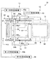
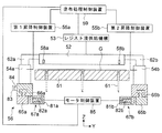
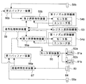
図1にLCD基板Gにレジスト膜(塗布膜)を形成するレジスト処理ユニット10の概略構造を示す平面図を示す。また、図2にレジスト塗布装置(CT)11の概略構造を示す正面図(図1におけるX方向から見た図であり、一部を断面で示す)を示す。さらに、図3にレジスト塗布装置(CT)11の概略制御ブロック図を示す。
FIG. 1 is a plan view showing a schematic structure of a
レジスト処理ユニット10は、LCD基板Gにレジスト液を塗布して塗布膜を形成するレジスト塗布装置(CT)11と、LCD基板Gに形成された塗布膜を減圧雰囲気に保持することにより乾燥させる減圧乾燥装置(VD)12と、レジスト塗布装置(CT)11から減圧乾燥装置(VD)12へLCD基板Gを搬送する基板搬送装置13と、を有している。
The
レジスト塗布装置(CT)11は、LCD基板Gを略水平姿勢に載置する載置台51と、載置台51に載置されたLCD基板Gにレジスト液を塗布するレジストノズル52と、レジストノズル52へのレジスト液供給およびレジストノズル52からのレジスト液の吐出制御を行うレジスト液供給機構53と、レジストノズル52を昇降させる第1・第2ノズル昇降機構54a・54bと、第1ノズル昇降機構54aの駆動を制御する第1昇降制御装置55aと、第2ノズル昇降機構54bの駆動を制御する第2昇降制御装置55bと、レジストノズル52と第1・第2ノズル昇降機構54a・54bとを一体的にX方向でスライドさせるノズルスライド機構56と、レジストノズル52の洗浄処理等を行うノズル洗浄ユニット57と、載置台51に載置されたLCD基板Gのうねりを検出するための変位センサ58a・58bと、レジスト塗布装置(CT)11全体の制御を司る塗布処理制御装置59と、を備えている。
The resist coating apparatus (CT) 11 includes a mounting table 51 for mounting the LCD substrate G in a substantially horizontal posture, a
また、レジスト塗布装置(CT)11は、変位センサ58aによる測定値に所定時間の遅延操作を行い、その遅延信号を第1昇降制御装置55aに送る第1バッファー装置86aと、変位センサ58bによる測定値に所定時間の遅延操作を行い、その遅延信号を第2昇降制御装置55bに送る第2バッファー装置86bと、第1・第2バッファー装置86a・86bにおける遅延時間を決定する遅延時間生成装置87を備えている。
Further, the resist coating device (CT) 11 performs a delay operation for a predetermined time on the measurement value by the
載置台51の表面には図示しない吸引孔が所定箇所に複数設けられており、LCD基板Gを減圧吸着することができるようになっている。また、載置台51を鉛直方向に貫通するように所定位置に昇降装置(図示せず)により昇降自在な昇降ピン61が設けられている。これらの昇降ピン61は、外部から載置台51へLCD基板Gを搬入する際およびレジスト膜が形成されたLCD基板Gを載置台51から搬出する際に、LCD基板Gを昇降させる。
A plurality of suction holes (not shown) are provided at predetermined positions on the surface of the mounting table 51 so that the LCD substrate G can be adsorbed under reduced pressure. In addition, elevating
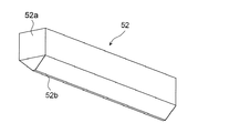
レジストノズル52は、図4に示す概略斜視図に示されるように、一方向に長い長尺状の箱体52aに、レジスト液を略帯状に吐出するスリット状のレジスト吐出口52bが設けられた構造を有している。このレジストノズル52は、箱体52aの長手方向をY方向に一致させた状態で、実質的に水平姿勢に保持されている(図1参照)。レジスト液供給機構53は、その詳細な構成は図示しないが、レジスト液を貯留するタンク、タンクからレジスト液をレジストノズル52へ送るポンプ、レジスト吐出口52bからのレジスト液の吐出タイミングを制御するバルブ等を備えている。
As shown in the schematic perspective view of FIG. 4, the
レジストノズル52はそのY方向端面で保持部材62a・62bに保持されており、第1・第2ノズル昇降機構54a・54bがそれぞれ保持部材62a・62bを支持している。
The
第1ノズル昇降機構54aは、図3に示されるように、保持部材62aを移動させるモータ部およびこのモータ部の駆動による保持部材62aの移動量を測定するエンコーダ部を備えている。このエンコーダ部による測定値とレジストノズル52の高さ位置とは予めリンクされており、保持部材62の移動量を測定することによってレジストノズル52の一端の高さを調整することができるようになっている。同様に、第2ノズル昇降機構54bもモータ部およびこのモータ部の駆動による保持部材62bの移動量、つまりレジストノズル52の他端の高さ位置を測定するエンコーダ部を備えている。
As shown in FIG. 3, the first
このように第1・第2ノズル昇降機構54a・54bはそれぞれ保持部材62a・62bの高さを独立して変化させることができるようになっているために、レジストノズル52を全体的に昇降させるだけでなく、保持部材62a・62bの高さを微少に変えることによって、レジストノズル52を微小に傾けることができるようになっている。
Since the first and second
但し、レジストノズル52はその位置制御を精密に行う必要があるために、堅固に保持部材62a・62bに保持され、かつ、保持部材62a・62bもまたそれぞれ第1・第2ノズル昇降機構54a・54bに堅固に保持されている必要があるために、レジストノズル52を傾けるにも構造上の限界がある。
However, since the position of the resist
このため、変位センサ58a・58bによる誤ったセンシング等によってレジストノズル52のY方向端の高さのずれが一定の範囲から外れることのないように、塗布処理制御装置59が第1・第2ノズル昇降機構54a・54bの各エンコーダ部による測定値を監視し、これらの測定値の差が予め定められた一定値よりも大きくなったときに、第1・第2昇降制御装置55a・55bをそれぞれ介して、第1・第2ノズル昇降機構54a・54bの駆動を停止するようになっている。これにより、レジストノズル52と保持部材62a・62bとの取り付け部分が損傷したり、レジストノズル52自体が変形する等の事故の発生が防止される。
For this reason, the coating
第1・第2ノズル昇降機構54a・54bとしては、レジストノズル52の昇降動作の精度を確保することができる範囲で、電磁リニアモータやボールネジ、ベルト駆動装置等から、適宜選択して用いることができる。
The first and second
ノズルスライド機構56は、X方向に延在するガイド65a・65bと、ガイド65a・65bにそれぞれ移動自在に嵌め合わされたスライドステージ66a・66bと、リニアモータ67a・67bとを備えている。第1ノズル昇降機構54aはスライドステージ66aに、第2ノズル昇降機構54bはスライドステージ66bにそれぞれ取り付けられている。
The
リニアモータ67aは、X方向に延在するマグネットレール81aと、スライドステージ66aに取り付けられ、マグネットレール81aに挿入配置されたコイル82aと、X方向に延在するリニアスケール83と、リニアスケール83を読み取るヘッド84と、コイル82aに所定の駆動信号を送るモータ制御装置85と、を備えている。また、リニアモータ67bは、X方向に延在するマグネットレール81bと、スライドステージ66bに取り付けられ、マグネットレール81bに挿入配置されたコイル82bとを備えている。
The linear motor 67a includes a
公知の通り、マグネットレール81a・81bはX方向にS極とN極とが所定間隔で交互に設けられた構造を有し、コイル82a・82bに所定の電流を流すことによって発生する磁場とこのマグネットレール81a・81bの磁場との間の吸引力と反発力によって、コイル82a・82bおよびスライドステージ66a・66bが一体的にX方向で移動する。
As is well known, the magnet rails 81a and 81b have a structure in which S poles and N poles are alternately provided in the X direction at a predetermined interval, and a magnetic field generated by flowing a predetermined current through the
モータ制御装置85は、ヘッド84の読み取り値とレジストノズル52を所定位置へ移動させるために塗布処理制御装置59から送られた指示値とを比較演算し、スライドステージ66a・66bをY方向に並んだ状態でX方向に移動させるために、所定の駆動信号をコイル82a・82bに同時に送る。レジスト塗布処理においては、レジストノズル52を高い精度で移動させることが好ましいために、リニアスケール83としては、例えば分解能が0.05μmというような高分解能のガラススケールが好適に用いられる。
The
ノズル洗浄ユニット57は、載置台51を挟んで減圧乾燥装置(VD)12とは反対側に設けられている。ノズル洗浄ユニット57は、LCD基板Gの載置台51への搬入時等にレジストノズル52を待避させる場でもある。ノズル洗浄ユニット57の詳細な構造の図示は省略するが、ノズル洗浄ユニット57は、LCD基板Gへのレジスト液供給前に予備的にレジストノズル52からレジスト液を吐出させる、所謂、ダミーディスペンスを行うためのダミーディスペンス部と、レジストノズル52のレジスト吐出口52bが乾燥しないようにレジスト吐出口52bを溶剤(例えば、シンナー)の蒸気雰囲気で保持するためのノズルバスと、レジストノズル52のレジスト吐出口52b近傍に付着したレジストを除去するためのノズル洗浄機構と、を備えている。
The
変位センサ58a・58bは、レジストノズル52が微少角度傾けられた場合にも常に垂直方向でセンシングするように、レジストノズル52のX方向側面(ノズル洗浄ユニット57側の側面)に取り付けられており、変位センサ58a・58bの直下におけるLCD基板Gの表面と変位センサ58a・58bとの間の距離を測定する。ここで、変位センサ58a・58bはレジストノズル52に取り付けられているから、変位センサ58a・58bによって測定されたLCD基板Gの表面と変位センサ58a・58bとの間の距離はそれぞれ、LCD基板Gの表面とレジストノズル52のレジスト吐出口52bとの間の距離に、第1・第2昇降制御装置55a・55bにおいて変換されるようになっている。
The
後に詳細に説明するように、変位センサ58aの測定信号は第1バッファー装置86aに送られ、そこで所定時間の遅延処理が行われた後に第1昇降制御装置55aへ送られるようになっている。同様に、変位センサ58bの測定信号は第2バッファー装置86bに送られ、そこで所定時間の遅延処理が行われた後に第2昇降制御装置55bへ送られる。この遅延処理の時間は遅延時間生成装置87によって決定される。
As will be described in detail later, the measurement signal of the
減圧乾燥装置(VD)12は、LCD基板Gを載置するための載置台68と、載置台68および載置台68に載置されたLCD基板Gを収容するチャンバ69とを備えている。減圧乾燥装置(VD)12に設けられた載置台68の表面には、LCD基板Gを支持するプロキシミティピン(図示せず)が所定位置に設けられている。チャンバは固定された下部容器と昇降自在な上部蓋体からなる上下2分割構造を有している。
The reduced pressure drying apparatus (VD) 12 includes a mounting table 68 for mounting the LCD substrate G, and a
基板搬送アーム13は、X方向、Y方向、Z方向(鉛直方向)に移動自在であり、LCD基板Gの裏面のY方向端面近傍でLCD基板Gを吸着保持する。基板搬送アーム13は、レジスト塗布装置(CT)11の載置台51上で昇降ピン61からLCD基板Gを受け取って、減圧乾燥装置(VD)12の載置台68へ保持したLCD基板Gを載置する。
The
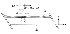
次に、レジスト塗布装置(CT)11におけるレジスト液塗布の制御について説明する。図5に変位センサ58a・58bとレジストノズル52との位置関係をY方向から見た側面図を示す。また、図6(a)に図5に示すP点上にレジストノズル52のレジスト吐出口52bが位置している状態を示すY−Z断面図を、図6(b)に図5に示すQ点上にレジストノズル52のレジスト吐出口52bが位置している状態を示すY−Z断面図をそれぞれ示す。
Next, control of resist solution application in the resist coating apparatus (CT) 11 will be described. FIG. 5 shows a side view of the positional relationship between the
図5はLCD基板Gの一部を示しており、LCD基板Gが完全に水平な状態ではなく、微少なうねりをもって載置台51に載置されている状態が示されている。このようなうねりは大型のLCD基板Gで生じやすい。例えば、LCD基板Gを載置台51に載置して真空吸着する際に、吸引孔が形成されている部分ではLCD基板Gは載置台51に密着するが、そうでない部分が浮き上がることによって、このようなうねりが生ずることがある。 FIG. 5 shows a part of the LCD substrate G, in which the LCD substrate G is not completely horizontal but is mounted on the mounting table 51 with a slight undulation. Such undulation is likely to occur on a large LCD substrate G. For example, when the LCD substrate G is placed on the mounting table 51 and vacuum-sucked, the LCD substrate G is in close contact with the mounting table 51 in the portion where the suction hole is formed, but the other portion is lifted, Such swell may occur.
図5および図6では、LCD基板Gは、P点を通るY方向において載置台51に密着しているが、Q点を通るY方向においては、第1ノズル昇降機構54a側で載置台51から僅かに浮いており、第2ノズル昇降機構54b側では第1ノズル昇降機構54a側よりもさらに載置台51から浮いた状態となっている。なお、図5および図6ではこのLCD基板Gのうねりを極端に大きく図示しているが、例えば、その高低差は、高々100μmまたはそれ以下である。
5 and 6, the LCD substrate G is in close contact with the mounting table 51 in the Y direction passing through the point P. However, in the Y direction passing through the Q point, the LCD substrate G is separated from the mounting table 51 on the first
LCD基板Gは、図6(a)に示す部分では水平であるため、レジストノズル52も水平に保持される。これにより、レジストノズル52のレジスト吐出口52bとLCD基板Gとの間隔は、全体的に距離ηで一定に維持される。仮に、レジストノズル52の姿勢を水平に維持したまま、レジストノズル52をQ点側へ向けてスキャンさせたとすると、LCD基板Gが浮き上がっているために、レジスト吐出口52bとLCD基板Gとの間隔は距離ηよりも短くなる。このようなLCD基板Gの表面とレジスト吐出口52bとの間の距離の変化によって、LCD基板Gにレジスト液を塗布した際に、膜厚が不均一性等の塗布むらが発生するおそれがある。
Since the LCD substrate G is horizontal in the portion shown in FIG. 6A, the resist
これを防止するために、図6(b)に示すように、LCD基板Gのうねりに対応させて、第1・第2ノズル昇降機構54a・54bの上昇距離を独立して調整することによりレジストノズル52を傾け、Q点を通るY方向において、レジスト吐出口52bとLCD基板Gとの間隔を全体的に距離ηで一定に維持することが好ましい。
In order to prevent this, as shown in FIG. 6B, the rising distances of the first and second
しかしながら、X方向において、変位センサ58a・58bがLCD基板Gのうねりを測定する位置とレジストノズル52のレジスト吐出口52bの位置との間には、距離δのずれがある。これは、レジスト吐出口52bの直下におけるLCD基板Gのうねりを検出することが装置構成上困難であることと、レジスト吐出口52bの直下におけるLCD基板Gのうねりを検出できたとしても、それからレジストノズル52の姿勢補正を行ったのでは、レジストノズル52は一定の速度でX方向にスキャンされているので、姿勢補正が終了した段階ではすでに測定点を通過してしまっていることとなり、レジストノズル52の姿勢補正を行う意味がなくなってしまう。
However, in the X direction, there is a shift of the distance δ between the position where the
このため、レジストノズル52のレジスト吐出口52bがQ点上に到達した際に、レジストノズル52の姿勢が図6(b)に示す状態となるように、第1・第2昇降制御装置55a・55bによる昇降駆動のタイミングを調整する必要がある。
For this reason, when the resist
そこで、先に図3に示したように、変位センサ58aの測定信号は第1バッファー装置86aに送られ、そこで所定時間の遅延処理が行われた後に第1昇降制御装置55aへ送られる。同様に、変位センサ58bの測定信号は第2バッファー装置86bに送られ、そこで所定時間の遅延処理が行われた後に第2昇降制御装置55bへ送られる。第1・第2バッファー装置86a・86bにおける信号遅延時間は、ヘッド84によるリニアスケール83の読み取り値と、レジストノズル52のスキャン速度と、レジスト吐出口52bと変位センサ58a・58b間の距離δと、第1・第2昇降制御装置55a・55bの演算速度とに基づいて、遅延時間生成装置87によって決定される。この信号遅延時間は、一度、最適な決定されたなら、レジストノズル52のスキャン条件等が変わらない限り、変更する必要はない。
Therefore, as previously shown in FIG. 3, the measurement signal of the
第1バッファー装置86aから出力された遅延処理後の測定信号を受信した第1昇降制御装置55aは、この遅延処理された測定信号と第1ノズル昇降機構54aのエンコーダ部からの信号とから、第1ノズル昇降機構54aのモータ部を駆動する駆動信号を生成し、これをそのモータ部に出力する。同様に、第2バッファー装置86bから出力された遅延処理後の測定信号を受けた第2昇降制御装置55bは、遅延処理後の測定信号と第2ノズル昇降機構54bのエンコーダ部からの信号とから、第2ノズル昇降機構54bのモータ部を駆動する駆動信号を生成し、これをそのモータ部に出力する。
The first elevating
こうしてレジストノズル52のレジスト吐出口52bがQ点上に到達した際に、Q点を通るY方向において、レジスト吐出口52bとLCD基板Gとの間隔が全体的に距離ηで一定となるように、レジストノズル52の姿勢を制御することができる。このようなレジストノズル52の高さ制御および姿勢制御を、レジストノズル52がLCD基板G上をスキャンしている間に一定の周期(すなわち、変位センサ58a・58bのサンプリング周期)で行うことにより、LCD基板G全体でLCD基板Gの表面とレジスト吐出口52bとの間の距離を一定に保持することができ、厚みむら等のない均質な塗布膜を形成することができる。
Thus, when the resist
第1・第2ノズル昇降機構54a・54bの各モータ部を駆動する駆動信号としては、保持部材62a・62bの位置を制御する制御するための速度信号や、保持部材62a・62bの移動速度を制御する加速度信号、が挙げられる。例えば、レジストノズル52のスキャン時間tを横軸に、変位センサ58aが測定する変位量Z(LCD基板Gのうねり)を縦軸にとると、これらの関係から、変位センサ58aによるサンプリング周期Ts内における変位量ΔZをそのサンプリング周期Tsで除する直線近似により、第1ノズル昇降機構54aを昇降させる速度信号を得ることができる。第2ノズル昇降機構54bを昇降させる速度信号もこれと同様に計算することができる。
As a drive signal for driving the motor units of the first and second
また、変位量ΔZが現実的なLCD基板Gのうねり量を超えている場合、例えば、1Hzのサンプリング周期で±50μmを超えた変位量が測定された場合(つまり、ΔZ>50μm/Tsの関係式が成立する場合)には、第1・第2ノズル昇降機構54a・54bを停止させる指令が第1・第2昇降制御装置55a・55bからそれぞれ第1・第2ノズル昇降機構54a・54bのモータ部に送られるようにすることが好ましい。
Further, when the displacement amount ΔZ exceeds the actual undulation amount of the LCD substrate G, for example, when a displacement amount exceeding ± 50 μm is measured at a sampling period of 1 Hz (that is, a relationship of ΔZ> 50 μm / Ts). When the equation is satisfied), a command to stop the first and second
次に、レジスト処理ユニット10におけるLCD基板Gの処理フローについて、以下に簡単に説明する。
最初に、レジストノズル52をノズル洗浄ユニット57のノズルバスに待機させておく。載置台51の上方に、例えば、Y方向からLCD基板Gを保持した搬送アームが進入してくると、昇降ピン61が上昇してLCD基板Gを支持する。そして、搬送アームを退出させた後に、昇降ピン61を降下させて、LCD基板Gを載置台51上に載置し、吸引孔からの吸気によりLCD基板Gを載置台51上に吸引固定する。
Next, the processing flow of the LCD substrate G in the resist processing
First, the resist
次いで、ノズル洗浄ユニット57においてレジストノズル52のダミーディスペンスを行った後に、レジストノズル52を載置台51の減圧乾燥装置(VD)12側へと移動させ、LCD基板Gにレジスト液を塗布するために、レジストノズル52を予め定められた初期の高さ位置に設定する。続いて、レジストノズル52をノズル洗浄ユニット57側へ所定の速度でスキャンさせながら、変位センサ58a・58bによるセンシングを所定のサンプリング周期で行い、LCD基板Gのうねりに対応させて、先に説明した第1・第2ノズル昇降機構54a・54bの動作制御を行いながら、レジスト吐出口52bからレジスト液を吐出することにより、LCD基板Gに塗布膜を形成する。
Next, after performing a dummy dispense of the resist
塗布膜の形成が終了したら、レジストノズル52をノズル洗浄ユニット57へ移動させて、そこでノズル洗浄を行い、再びノズルバスに待機させる。塗布膜が形成されたLCD基板Gは、昇降ピン61によって所定の高さに持ち上げられた後に基板搬送装置13によって保持され、減圧乾燥装置(VD)12の載置台68に載置され、チャンバ69に収容される。そして、チャンバ69内を減圧雰囲気に保持することより塗布膜に含まれる揮発成分を蒸発させる。このような乾燥処理が終了したLCD基板Gは、図示しない基板搬送装置によって、減圧乾燥装置(VD)12から、例えば、塗布膜の熱的乾燥処理を行う装置へと、搬出される。
When the formation of the coating film is completed, the resist
以上、本発明の実施の形態について説明したが、本発明はこのような形態に限定されるものではない。例えば、上記説明においては2つの変位センサ58a・58bを用い、第1・第2ノズル昇降機構54a・54bを独立に制御することによりレジストノズル52の姿勢を制御したが、レジストノズル52の長手方向中央部に変位センサを1つ設け、これによりLCD基板GのうねりをLCD基板Gの中心部で測定し、その測定値に基づいて第1・第2ノズル昇降機構54a・54bを同期させて制御してもよい。
As mentioned above, although embodiment of this invention was described, this invention is not limited to such a form. For example, in the above description, the position of the resist
また、上記説明においては、第1昇降制御装置55aにおいて第1ノズル昇降機構54aの駆動信号を発生させる演算処理を行ったが、変位センサ58aの検出信号を受信した第1バッファー装置86aにおいて、信号遅延処理に加えて、微分処理を行うことによって速度信号に変換してもよい。この場合には、第1ノズル昇降機構54aのエンコーダ部から出力される信号もまた第1昇降制御装置55aに入力される前に微分処理して速度信号に変換しておく。これにより第1昇降制御装置55aにおける演算負荷を小さくすることができる。第2ノズル昇降機構54bの制御も同様に行うことが好ましい。
In the above description, the calculation process for generating the drive signal of the first
さらに、第1・第2ノズル昇降機構54a・54bの駆動制御に、これらが有するエンコーダ部を用いたが、別途に高分解能のリニアスケールを配設し、そのリニアスケールによる測定値を第1・第2ノズル昇降機構54a・54bの各モータ部の駆動制御に用いることも好ましい。さらに、このようなリニアスケールと第1・第2ノズル昇降機構54a・54bがそれぞれ具備するエンコーダ部とを切り替えて、使用することができる構成としてもよい。この場合、例えば、通常の塗布膜形成処理ではエンコーダ部を用い、非常に高い膜厚均一性が要求される塗布膜形成処理ではリニアスケールを用いるというような、使い分けをすることができる。
Furthermore, although the encoder part which these have was used for the drive control of the 1st, 2nd nozzle raising /
さらにまた、上記実施の形態においては、変位センサ58a・58bの測定値に基づき、そのサンプリング周期にしたがってレジストノズル52の両端の高さを独立して微調整したが、要求される膜厚均一性が得られる限りにおいて、以下の2つの制御方法を用いることも可能である。
Furthermore, in the above embodiment, the height of both ends of the resist
その1の制御方法は、LCD基板Gの第1ノズル昇降機構54a側におけるレジスト吐出口52bとLCD基板Gとの間の距離がη±κの範囲内にあり、LCD基板Gの第2ノズル昇降機構54b側におけるレジスト吐出口52bとLCD基板Gとの間の距離もまたη±κの範囲内にある場合には、第1・第2ノズル昇降機構54a・54bの駆動を行わないように制御する方法である。この場合には、レジストノズル52が一定角度以上に傾かないように、η±κの値を定めることがことが好ましい。
The first control method is that the distance between the resist
別の制御方法は、変位センサ58a・58bによる測定値を平均化し、レジストノズル52の姿勢が常に水平姿勢に保持されるように第1ノズル昇降機構54aと第2ノズル昇降機構43bを同期させて昇降させることにより、LCD基板Gのうねりの平均高さとレジスト吐出口52bとの間の距離を一定に保持する方法である。この場合、変位センサ58a・58bによる各測定値とこれらの平均値との差が予め定めた値よりも大きくなったときに、警報を発したり、またはレジストノズル52からのレジスト液の吐出を停止する等の措置がとられるようにすることが好ましい。
Another control method is to average the measured values of the
上記説明においては、載置台51に載置されたLCD基板Gにうねりが生じている場合について説明したが、LCD基板Gにはガラス基板の製造方法に起因して、例えば、十数μmの厚みむらが存在することが殆どである。このため、LCD基板Gがうねりなく載置台51に載置されていた場合にも、本発明に係る塗布処理方法を用いれば、LCD基板G自体が有する厚みむらに対応して、均一性に優れた塗布膜を形成することができる。 In the above description, the case where the LCD substrate G mounted on the mounting table 51 is wavy has been described. However, the LCD substrate G has a thickness of, for example, several tens of μm due to the glass substrate manufacturing method. Mostly, unevenness exists. For this reason, even when the LCD substrate G is mounted on the mounting table 51 without undulations, if the coating processing method according to the present invention is used, the LCD substrate G itself has excellent uniformity corresponding to the thickness unevenness of the LCD substrate G itself. A coated film can be formed.
また、上記説明においては、固定されたLCD基板G上でレジストノズル52をスキャンさせる構成を例に説明したが、レジストノズル52を固定し、載置台51をスキャンさせる構成としてもよい。また、表面から空気または窒素ガス等を吹き出させるエアーステージを用い、LCD基板Gをこのエアーステージ上で滑るように移動させながら、レジスト液をLCD基板Gに塗布する構成についても、本発明に係る塗布処理方法を用いることができる。
In the above description, the configuration in which the resist
さらに上記説明においては、塗布膜としてレジスト膜を取り上げたが、塗布膜はこれに限定されるものではなく、反射防止膜や感光性を有さない絶縁膜等であってもよい。 Further, in the above description, the resist film is taken up as the coating film. However, the coating film is not limited to this, and may be an antireflection film, an insulating film having no photosensitivity, or the like.
本発明は、LCDガラス基板等の大型基板にレジスト膜等の塗布膜を形成するレジスト膜形成装置等に好適である。 The present invention is suitable for a resist film forming apparatus that forms a coating film such as a resist film on a large substrate such as an LCD glass substrate.
10;レジスト処理ユニット
11;レジスト塗布装置(CT)
12;減圧乾燥装置(VD)
13;基板搬送装置
51;載置台
52;レジストノズル
53;レジスト液供給機構
54a;第1ノズル昇降機構
54b;第2ノズル昇降機構
55a;第1昇降制御装置
55b;第2昇降制御装置
56;ノズルスライド機構
57;ノズル洗浄ユニット
58a・58b;変位センサ
59;塗布処理制御装置
86a;第1バッファー装置
86b;第2バッファー装置
87;遅延時間生成装置
G;LCD基板
10; resist processing
12: Vacuum drying equipment (VD)
13;
Claims (9)
所定の塗布液を吐出する塗布液吐出口を備えた塗布液ノズルと、
前記塗布液ノズルを昇降させるノズル昇降機構と、
前記ノズル昇降機構の昇降制御を行う昇降制御装置と、
前記基板と前記塗布液ノズルとを相対的に移動させる移動機構と、
前記塗布液ノズルによって塗布液が塗布される方向の前記塗布液吐出口から所定距離前方における基板のうねりを測定する変位センサと、
前記変位センサによる測定値に所定時間の遅延操作を行い、その遅延信号を前記昇降制御装置に送るバッファー装置と、
前記バッファー装置における遅延時間を決定する遅延時間生成装置と、
を具備し、
前記塗布液ノズルから塗布液を吐出させながら前記基板と前記塗布液ノズルとを相対的に移動させることによって前記基板の表面に塗布膜を形成する際に、前記昇降制御装置は、前記塗布液ノズルの塗布液吐出口と前記基板との間の距離が一定となるように、前記塗布液ノズルを前記基板のうねりに適応させて昇降させることを特徴とする塗布膜形成装置。 A coating film forming apparatus for forming a coating film by supplying a predetermined coating liquid to a substrate held in a substantially horizontal posture,
A coating liquid nozzle having a coating liquid discharge port for discharging a predetermined coating liquid;
A nozzle lifting mechanism for lifting and lowering the coating liquid nozzle;
A lifting control device for performing lifting control of the nozzle lifting mechanism;
A moving mechanism for relatively moving the substrate and the coating liquid nozzle;
A displacement sensor for measuring the waviness of the substrate in a predetermined distance forward from the coating liquid discharge port in the direction in which the coating liquid is applied by the coating liquid nozzle;
A buffer device for performing a delay operation for a predetermined time on the measurement value by the displacement sensor and sending the delay signal to the elevation control device;
A delay time generating device for determining a delay time in the buffer device;
Comprising
When forming the coating film on the surface of the substrate by relatively moving the substrate and the coating solution nozzle while discharging the coating solution from the coating solution nozzle, the elevating control device is configured to use the coating solution nozzle. A coating film forming apparatus, wherein the coating liquid nozzle is moved up and down in accordance with the undulation of the substrate so that the distance between the coating liquid discharge port and the substrate is constant.
前記塗布液ノズルの高さを測定するリニアスケールと、前記ノズル昇降機構のエンコーダ部と前記リニアスケールとを切り替える切替器と、をさらに具備し、
前記昇降制御装置は、前記切替器によって選択された前記ノズル昇降機構のエンコーダ部または前記リニアスケールのいずれか一方の測定値を用いて、前記ノズル昇降機構の駆動部を駆動するための制御信号を発生させることを特徴とする請求項1から請求項3のいずれか1項に記載の塗布膜形成装置。 The nozzle lifting mechanism has a drive part and an encoder part,
A linear scale for measuring the height of the coating liquid nozzle, and a switch for switching between the encoder unit of the nozzle lifting mechanism and the linear scale,
The lifting control device uses the measured value of either the encoder unit of the nozzle lifting mechanism or the linear scale selected by the switch to generate a control signal for driving the driving unit of the nozzle lifting mechanism. The coating film forming apparatus according to any one of claims 1 to 3, wherein the coating film forming apparatus is generated.
所定の塗布液を略帯状に吐出する塗布液吐出口を備えた長尺状の塗布液ノズルと、
実質的に前記塗布液ノズルの長手方向の一端を保持し、前記塗布液ノズルを昇降させる第1ノズル昇降機構と、
実質的に前記塗布液ノズルの長手方向の他端を保持し、前記塗布液ノズルを昇降させる第2ノズル昇降機構と、
前記第1ノズル昇降機構の昇降制御を行う第1昇降制御装置と、
前記第2ノズル昇降機構の昇降制御を行う第2昇降制御装置と、
前記基板と前記塗布液ノズルとを相対的に移動させるためのモータおよびリニアスケールを備えた移動機構と、
前記基板のうねりを、前記塗布液ノズルによって塗布液が塗布される方向の前記塗布液吐出口から所定距離前方、かつ、前記基板の端部において測定する第1変位センサおよび第2変位センサと、
前記第1変位センサによる測定値に所定時間の遅延操作を行い、その遅延信号を前記第1昇降制御装置に送る第1バッファー装置と、
前記第2変位センサによる測定値に所定時間の遅延操作を行い、その遅延信号を前記第2昇降制御装置に送る第2バッファー装置と、
前記第1バッファー装置および前記第2バッファー装置における遅延時間を決定する遅延時間生成装置と、
を具備し、
前記塗布液ノズルから塗布液を吐出させながら前記基板と前記塗布液ノズルとを相対的に移動させることによって前記基板の表面に塗布膜を形成する際に、前記第1昇降制御装置および前記第2昇降制御装置は、前記塗布液ノズルの塗布液吐出口と前記基板との間の距離が一定となるように、前記基板のうねりに適応させて前記塗布液ノズルの昇降および傾斜姿勢の制御を行うことを特徴とする塗布膜形成装置。 A coating film forming apparatus for forming a coating film by supplying a predetermined coating liquid to a substrate held in a substantially horizontal posture,
An elongated coating liquid nozzle having a coating liquid discharge port for discharging a predetermined coating liquid in a substantially strip shape;
A first nozzle lifting mechanism that substantially holds one end of the coating liquid nozzle in the longitudinal direction and lifts the coating liquid nozzle;
A second nozzle raising / lowering mechanism that substantially holds the other end in the longitudinal direction of the coating liquid nozzle and raises and lowers the coating liquid nozzle;
A first elevating control device for performing elevating control of the first nozzle elevating mechanism;
A second lifting control device for performing lifting control of the second nozzle lifting mechanism;
A moving mechanism including a motor and a linear scale for relatively moving the substrate and the coating liquid nozzle;
A first displacement sensor and a second displacement sensor for measuring the waviness of the substrate at a predetermined distance in front of the coating solution discharge port in the direction in which the coating solution is applied by the coating solution nozzle and at the end of the substrate;
A first buffer device that performs a delay operation for a predetermined time on a measured value by the first displacement sensor, and sends the delay signal to the first lifting control device;
A second buffer device that performs a delay operation for a predetermined time on a measurement value obtained by the second displacement sensor, and sends the delay signal to the second lift control device;
A delay time generating device for determining a delay time in the first buffer device and the second buffer device;
Comprising
When forming a coating film on the surface of the substrate by relatively moving the substrate and the coating solution nozzle while discharging the coating solution from the coating solution nozzle, the first elevating control device and the second The elevation controller controls the elevation and inclination of the coating solution nozzle in accordance with the undulation of the substrate so that the distance between the coating solution discharge port of the coating solution nozzle and the substrate is constant. A coating film forming apparatus.
前記塗布液ノズルの一端の高さを測定する第1リニアスケールと、前記塗布液ノズルの他端の高さを測定する第2リニアスケールと、前記第1ノズル昇降機構のエンコーダ部と前記第1リニアスケールとを切り替える第1切替器と、前記第2ノズル昇降機構のエンコーダ部と前記第2リニアスケールとを切り替える第2切替器をさらに具備し、
前記第1,第2昇降制御装置は、前記第1,第2切替器によって選択された前記第1,第2ノズル昇降機構のエンコーダ部または前記第1,第2リニアスケールのいずれか一方の測定値を用いて、前記第1,第2ノズル昇降機構の駆動部を駆動するための制御信号を発生させることを特徴とする請求項5から請求項7のいずれか1項に記載の塗布膜形成装置。 Each of the first and second nozzle lifting mechanisms has a drive unit and an encoder unit,
A first linear scale that measures the height of one end of the coating liquid nozzle; a second linear scale that measures the height of the other end of the coating liquid nozzle; an encoder unit of the first nozzle lifting mechanism; and the first A first switch for switching between the linear scale, and a second switch for switching between the encoder unit of the second nozzle lifting mechanism and the second linear scale,
The first and second lifting control devices measure either the encoder unit of the first or second nozzle lifting mechanism selected by the first or second switch or the first or second linear scale. 8. The coating film formation according to claim 5, wherein a control signal for driving the drive unit of the first and second nozzle lifting mechanisms is generated using the value. 9. apparatus.
Priority Applications (1)
| Application Number | Priority Date | Filing Date | Title |
|---|---|---|---|
| JP2004121185A JP4372606B2 (en) | 2004-04-16 | 2004-04-16 | Coating film forming device |
Applications Claiming Priority (1)
| Application Number | Priority Date | Filing Date | Title |
|---|---|---|---|
| JP2004121185A JP4372606B2 (en) | 2004-04-16 | 2004-04-16 | Coating film forming device |
Publications (2)
| Publication Number | Publication Date |
|---|---|
| JP2005296907A true JP2005296907A (en) | 2005-10-27 |
| JP4372606B2 JP4372606B2 (en) | 2009-11-25 |
Family
ID=35329097
Family Applications (1)
| Application Number | Title | Priority Date | Filing Date |
|---|---|---|---|
| JP2004121185A Expired - Lifetime JP4372606B2 (en) | 2004-04-16 | 2004-04-16 | Coating film forming device |
Country Status (1)
| Country | Link |
|---|---|
| JP (1) | JP4372606B2 (en) |
Cited By (8)
| Publication number | Priority date | Publication date | Assignee | Title |
|---|---|---|---|---|
| KR100685216B1 (en) | 2004-10-07 | 2007-02-22 | 다이니폰 스크린 세이조우 가부시키가이샤 | Substrate processing apparatus and substrate processing method |
| JP2007152261A (en) * | 2005-12-06 | 2007-06-21 | Shibaura Mechatronics Corp | Paste coating apparatus, paste coating method, and display panel manufacturing apparatus using the same |
| KR100739310B1 (en) | 2005-09-21 | 2007-07-12 | 도쿄 오카 고교 가부시키가이샤 | Coating device and coating method |
| JP2008006439A (en) * | 2006-06-28 | 2008-01-17 | Top Engineering Co Ltd | Head unit of paste dispenser |
| JP2008032481A (en) * | 2006-07-27 | 2008-02-14 | Toray Eng Co Ltd | Method of measuring distance between member, nozzle height adjustment method for applicator, and applicator |
| JP2008311442A (en) * | 2007-06-14 | 2008-12-25 | Tosoh Corp | Surface processing method and surface processing apparatus |
| KR101000549B1 (en) * | 2008-09-19 | 2010-12-14 | 주식회사 디엠에스 | Photoresist coating device |
| TWI723196B (en) * | 2016-09-30 | 2021-04-01 | 日商東京應化工業股份有限公司 | Coating apparatus and coating method |
Families Citing this family (1)
| Publication number | Priority date | Publication date | Assignee | Title |
|---|---|---|---|---|
| KR102216431B1 (en) * | 2018-12-14 | 2021-02-17 | 주식회사 탑앤씨 | Apparatus for coating surface treatment of pouch and manufacture method therefor |
-
2004
- 2004-04-16 JP JP2004121185A patent/JP4372606B2/en not_active Expired - Lifetime
Cited By (9)
| Publication number | Priority date | Publication date | Assignee | Title |
|---|---|---|---|---|
| KR100685216B1 (en) | 2004-10-07 | 2007-02-22 | 다이니폰 스크린 세이조우 가부시키가이샤 | Substrate processing apparatus and substrate processing method |
| KR100739310B1 (en) | 2005-09-21 | 2007-07-12 | 도쿄 오카 고교 가부시키가이샤 | Coating device and coating method |
| JP2007152261A (en) * | 2005-12-06 | 2007-06-21 | Shibaura Mechatronics Corp | Paste coating apparatus, paste coating method, and display panel manufacturing apparatus using the same |
| JP2008006439A (en) * | 2006-06-28 | 2008-01-17 | Top Engineering Co Ltd | Head unit of paste dispenser |
| JP2008032481A (en) * | 2006-07-27 | 2008-02-14 | Toray Eng Co Ltd | Method of measuring distance between member, nozzle height adjustment method for applicator, and applicator |
| JP2008311442A (en) * | 2007-06-14 | 2008-12-25 | Tosoh Corp | Surface processing method and surface processing apparatus |
| KR101000549B1 (en) * | 2008-09-19 | 2010-12-14 | 주식회사 디엠에스 | Photoresist coating device |
| CN101676802B (en) * | 2008-09-19 | 2012-05-16 | 显示器生产服务株式会社 | Light sensitive liquid coating apparatus |
| TWI723196B (en) * | 2016-09-30 | 2021-04-01 | 日商東京應化工業股份有限公司 | Coating apparatus and coating method |
Also Published As
| Publication number | Publication date |
|---|---|
| JP4372606B2 (en) | 2009-11-25 |
Similar Documents
| Publication | Publication Date | Title |
|---|---|---|
| KR102018506B1 (en) | Coating divece | |
| US6736987B1 (en) | Silicon etching apparatus using XeF2 | |
| JP4033841B2 (en) | Floating substrate transfer processing method and apparatus | |
| JP4652351B2 (en) | Substrate support apparatus and substrate support method | |
| JP4372606B2 (en) | Coating film forming device | |
| KR102856881B1 (en) | Bonding apparatus, bonding system, bonding method, and computer recording medium | |
| KR102776950B1 (en) | Alignment device, alignment method, film forming apparatus, and film forming method | |
| TWI595594B (en) | Substrate holding device, coating device, substrate holding method | |
| US11658146B2 (en) | Bonding apparatus, bonding system, bonding method, and recording medium | |
| JP2007150280A (en) | Substrate support apparatus, substrate support method, substrate processing apparatus, substrate processing method, and manufacturing method of display device constituent member | |
| KR20120109304A (en) | Floating substrate coating apparatus | |
| KR101074169B1 (en) | A Device and Method for Adjusting Height of Coating Apparatus and A Coating Apparatus Having the Same | |
| JP4403592B2 (en) | Coating apparatus, substrate manufacturing method, and color filter manufacturing apparatus and manufacturing method using the same | |
| KR20110059398A (en) | Dispenser appratus and method for the same | |
| KR100685216B1 (en) | Substrate processing apparatus and substrate processing method | |
| JP2012023104A (en) | Substrate-setting device | |
| JPH11300258A (en) | Coating device and coating method, color filter manufacturing device and its manufacturing method | |
| JP2003243286A (en) | Substrate processing equipment | |
| CN100409424C (en) | Substrate processing equipment | |
| JPH07335718A (en) | Wafer carrier device | |
| US7267128B2 (en) | Substrate treating apparatus | |
| JPH11253869A (en) | Coating device | |
| JP2005263336A (en) | Substrate transport mechanism and coating film forming apparatus | |
| JP2020054973A (en) | Substrate processing apparatus and substrate processing method | |
| JP2001321710A (en) | Coating equipment |
Legal Events
| Date | Code | Title | Description |
|---|---|---|---|
| A621 | Written request for application examination |
Free format text: JAPANESE INTERMEDIATE CODE: A621 Effective date: 20060606 |
|
| A521 | Request for written amendment filed |
Free format text: JAPANESE INTERMEDIATE CODE: A523 Effective date: 20080501 |
|
| A711 | Notification of change in applicant |
Free format text: JAPANESE INTERMEDIATE CODE: A711 Effective date: 20080501 |
|
| RD02 | Notification of acceptance of power of attorney |
Free format text: JAPANESE INTERMEDIATE CODE: A7422 Effective date: 20080501 |
|
| A521 | Request for written amendment filed |
Free format text: JAPANESE INTERMEDIATE CODE: A821 Effective date: 20080501 |
|
| A977 | Report on retrieval |
Free format text: JAPANESE INTERMEDIATE CODE: A971007 Effective date: 20090424 |
|
| A131 | Notification of reasons for refusal |
Free format text: JAPANESE INTERMEDIATE CODE: A131 Effective date: 20090526 |
|
| A521 | Request for written amendment filed |
Free format text: JAPANESE INTERMEDIATE CODE: A523 Effective date: 20090724 |
|
| TRDD | Decision of grant or rejection written | ||
| A01 | Written decision to grant a patent or to grant a registration (utility model) |
Free format text: JAPANESE INTERMEDIATE CODE: A01 Effective date: 20090901 |
|
| A01 | Written decision to grant a patent or to grant a registration (utility model) |
Free format text: JAPANESE INTERMEDIATE CODE: A01 |
|
| A61 | First payment of annual fees (during grant procedure) |
Free format text: JAPANESE INTERMEDIATE CODE: A61 Effective date: 20090902 |
|
| FPAY | Renewal fee payment (event date is renewal date of database) |
Free format text: PAYMENT UNTIL: 20120911 Year of fee payment: 3 |
|
| R150 | Certificate of patent or registration of utility model |
Ref document number: 4372606 Country of ref document: JP Free format text: JAPANESE INTERMEDIATE CODE: R150 Free format text: JAPANESE INTERMEDIATE CODE: R150 |
|
| FPAY | Renewal fee payment (event date is renewal date of database) |
Free format text: PAYMENT UNTIL: 20120911 Year of fee payment: 3 |
|
| FPAY | Renewal fee payment (event date is renewal date of database) |
Free format text: PAYMENT UNTIL: 20130911 Year of fee payment: 4 |
|
| R250 | Receipt of annual fees |
Free format text: JAPANESE INTERMEDIATE CODE: R250 |
|
| R250 | Receipt of annual fees |
Free format text: JAPANESE INTERMEDIATE CODE: R250 |
|
| R250 | Receipt of annual fees |
Free format text: JAPANESE INTERMEDIATE CODE: R250 |
|
| R250 | Receipt of annual fees |
Free format text: JAPANESE INTERMEDIATE CODE: R250 |
|
| R250 | Receipt of annual fees |
Free format text: JAPANESE INTERMEDIATE CODE: R250 |
|
| R250 | Receipt of annual fees |
Free format text: JAPANESE INTERMEDIATE CODE: R250 |
|
| R250 | Receipt of annual fees |
Free format text: JAPANESE INTERMEDIATE CODE: R250 |
|
| R250 | Receipt of annual fees |
Free format text: JAPANESE INTERMEDIATE CODE: R250 |
|
| R250 | Receipt of annual fees |
Free format text: JAPANESE INTERMEDIATE CODE: R250 |
|
| R250 | Receipt of annual fees |
Free format text: JAPANESE INTERMEDIATE CODE: R250 |
|
| R250 | Receipt of annual fees |
Free format text: JAPANESE INTERMEDIATE CODE: R250 |
|
| R250 | Receipt of annual fees |
Free format text: JAPANESE INTERMEDIATE CODE: R250 |
|
| EXPY | Cancellation because of completion of term |