JP2005296859A - Harmful substance decomposition method and harmful substance decomposition apparatus - Google Patents
Harmful substance decomposition method and harmful substance decomposition apparatus Download PDFInfo
- Publication number
- JP2005296859A JP2005296859A JP2004118499A JP2004118499A JP2005296859A JP 2005296859 A JP2005296859 A JP 2005296859A JP 2004118499 A JP2004118499 A JP 2004118499A JP 2004118499 A JP2004118499 A JP 2004118499A JP 2005296859 A JP2005296859 A JP 2005296859A
- Authority
- JP
- Japan
- Prior art keywords
- photocatalyst
- harmful substance
- decomposing
- light
- light source
- Prior art date
- Legal status (The legal status is an assumption and is not a legal conclusion. Google has not performed a legal analysis and makes no representation as to the accuracy of the status listed.)
- Pending
Links
- 239000000126 substance Substances 0.000 title claims abstract description 52
- 238000000034 method Methods 0.000 title claims abstract description 24
- 238000000354 decomposition reaction Methods 0.000 title claims abstract description 22
- 239000011941 photocatalyst Substances 0.000 claims abstract description 88
- 239000000919 ceramic Substances 0.000 claims abstract description 33
- 239000000383 hazardous chemical Substances 0.000 claims description 3
- 230000001678 irradiating effect Effects 0.000 claims description 3
- 231100000167 toxic agent Toxicity 0.000 claims 2
- 239000003440 toxic substance Substances 0.000 claims 2
- 239000002699 waste material Substances 0.000 abstract description 5
- 239000007789 gas Substances 0.000 description 32
- 230000001877 deodorizing effect Effects 0.000 description 19
- OKTJSMMVPCPJKN-UHFFFAOYSA-N Carbon Chemical group [C] OKTJSMMVPCPJKN-UHFFFAOYSA-N 0.000 description 7
- 230000000694 effects Effects 0.000 description 6
- 230000001699 photocatalysis Effects 0.000 description 6
- 238000013032 photocatalytic reaction Methods 0.000 description 6
- CBENFWSGALASAD-UHFFFAOYSA-N Ozone Chemical compound [O-][O+]=O CBENFWSGALASAD-UHFFFAOYSA-N 0.000 description 5
- 235000019645 odor Nutrition 0.000 description 5
- 238000000746 purification Methods 0.000 description 5
- GWEVSGVZZGPLCZ-UHFFFAOYSA-N Titan oxide Chemical compound O=[Ti]=O GWEVSGVZZGPLCZ-UHFFFAOYSA-N 0.000 description 4
- 238000006243 chemical reaction Methods 0.000 description 4
- 238000010586 diagram Methods 0.000 description 4
- 238000001179 sorption measurement Methods 0.000 description 4
- OGIDPMRJRNCKJF-UHFFFAOYSA-N titanium oxide Inorganic materials [Ti]=O OGIDPMRJRNCKJF-UHFFFAOYSA-N 0.000 description 4
- 229910021536 Zeolite Inorganic materials 0.000 description 3
- 239000003463 adsorbent Substances 0.000 description 3
- 239000003795 chemical substances by application Substances 0.000 description 3
- 238000004332 deodorization Methods 0.000 description 3
- HNPSIPDUKPIQMN-UHFFFAOYSA-N dioxosilane;oxo(oxoalumanyloxy)alumane Chemical compound O=[Si]=O.O=[Al]O[Al]=O HNPSIPDUKPIQMN-UHFFFAOYSA-N 0.000 description 3
- 239000010457 zeolite Substances 0.000 description 3
- XLOMVQKBTHCTTD-UHFFFAOYSA-N Zinc monoxide Chemical compound [Zn]=O XLOMVQKBTHCTTD-UHFFFAOYSA-N 0.000 description 2
- 238000004887 air purification Methods 0.000 description 2
- 230000005284 excitation Effects 0.000 description 2
- 238000011144 upstream manufacturing Methods 0.000 description 2
- JRPBQTZRNDNNOP-UHFFFAOYSA-N barium titanate Chemical compound [Ba+2].[Ba+2].[O-][Ti]([O-])([O-])[O-] JRPBQTZRNDNNOP-UHFFFAOYSA-N 0.000 description 1
- 229910002113 barium titanate Inorganic materials 0.000 description 1
- 230000001627 detrimental effect Effects 0.000 description 1
- 239000012530 fluid Substances 0.000 description 1
- 239000002440 industrial waste Substances 0.000 description 1
- 239000010410 layer Substances 0.000 description 1
- 239000002346 layers by function Substances 0.000 description 1
- 230000001590 oxidative effect Effects 0.000 description 1
- 239000011148 porous material Substances 0.000 description 1
- 238000009790 rate-determining step (RDS) Methods 0.000 description 1
- 230000008929 regeneration Effects 0.000 description 1
- 238000011069 regeneration method Methods 0.000 description 1
- VEALVRVVWBQVSL-UHFFFAOYSA-N strontium titanate Chemical compound [Sr+2].[O-][Ti]([O-])=O VEALVRVVWBQVSL-UHFFFAOYSA-N 0.000 description 1
- 239000000758 substrate Substances 0.000 description 1
- 238000005406 washing Methods 0.000 description 1
- XLYOFNOQVPJJNP-UHFFFAOYSA-N water Substances O XLYOFNOQVPJJNP-UHFFFAOYSA-N 0.000 description 1
- 239000011787 zinc oxide Substances 0.000 description 1
Images
Classifications
-
- A—HUMAN NECESSITIES
- A61—MEDICAL OR VETERINARY SCIENCE; HYGIENE
- A61L—METHODS OR APPARATUS FOR STERILISING MATERIALS OR OBJECTS IN GENERAL; DISINFECTION, STERILISATION OR DEODORISATION OF AIR; CHEMICAL ASPECTS OF BANDAGES, DRESSINGS, ABSORBENT PADS OR SURGICAL ARTICLES; MATERIALS FOR BANDAGES, DRESSINGS, ABSORBENT PADS OR SURGICAL ARTICLES
- A61L9/00—Disinfection, sterilisation or deodorisation of air
- A61L9/16—Disinfection, sterilisation or deodorisation of air using physical phenomena
- A61L9/18—Radiation
- A61L9/20—Ultraviolet radiation
- A61L9/205—Ultraviolet radiation using a photocatalyst or photosensitiser
-
- A—HUMAN NECESSITIES
- A61—MEDICAL OR VETERINARY SCIENCE; HYGIENE
- A61L—METHODS OR APPARATUS FOR STERILISING MATERIALS OR OBJECTS IN GENERAL; DISINFECTION, STERILISATION OR DEODORISATION OF AIR; CHEMICAL ASPECTS OF BANDAGES, DRESSINGS, ABSORBENT PADS OR SURGICAL ARTICLES; MATERIALS FOR BANDAGES, DRESSINGS, ABSORBENT PADS OR SURGICAL ARTICLES
- A61L9/00—Disinfection, sterilisation or deodorisation of air
- A61L9/16—Disinfection, sterilisation or deodorisation of air using physical phenomena
- A61L9/18—Radiation
-
- A—HUMAN NECESSITIES
- A61—MEDICAL OR VETERINARY SCIENCE; HYGIENE
- A61L—METHODS OR APPARATUS FOR STERILISING MATERIALS OR OBJECTS IN GENERAL; DISINFECTION, STERILISATION OR DEODORISATION OF AIR; CHEMICAL ASPECTS OF BANDAGES, DRESSINGS, ABSORBENT PADS OR SURGICAL ARTICLES; MATERIALS FOR BANDAGES, DRESSINGS, ABSORBENT PADS OR SURGICAL ARTICLES
- A61L9/00—Disinfection, sterilisation or deodorisation of air
- A61L9/01—Deodorant compositions
-
- A—HUMAN NECESSITIES
- A61—MEDICAL OR VETERINARY SCIENCE; HYGIENE
- A61L—METHODS OR APPARATUS FOR STERILISING MATERIALS OR OBJECTS IN GENERAL; DISINFECTION, STERILISATION OR DEODORISATION OF AIR; CHEMICAL ASPECTS OF BANDAGES, DRESSINGS, ABSORBENT PADS OR SURGICAL ARTICLES; MATERIALS FOR BANDAGES, DRESSINGS, ABSORBENT PADS OR SURGICAL ARTICLES
- A61L9/00—Disinfection, sterilisation or deodorisation of air
- A61L9/16—Disinfection, sterilisation or deodorisation of air using physical phenomena
- A61L9/18—Radiation
- A61L9/20—Ultraviolet radiation
-
- B—PERFORMING OPERATIONS; TRANSPORTING
- B01—PHYSICAL OR CHEMICAL PROCESSES OR APPARATUS IN GENERAL
- B01D—SEPARATION
- B01D53/00—Separation of gases or vapours; Recovering vapours of volatile solvents from gases; Chemical or biological purification of waste gases, e.g. engine exhaust gases, smoke, fumes, flue gases, aerosols
- B01D53/34—Chemical or biological purification of waste gases
- B01D53/74—General processes for purification of waste gases; Apparatus or devices specially adapted therefor
- B01D53/86—Catalytic processes
- B01D53/88—Handling or mounting catalysts
- B01D53/885—Devices in general for catalytic purification of waste gases
-
- B—PERFORMING OPERATIONS; TRANSPORTING
- B01—PHYSICAL OR CHEMICAL PROCESSES OR APPARATUS IN GENERAL
- B01J—CHEMICAL OR PHYSICAL PROCESSES, e.g. CATALYSIS OR COLLOID CHEMISTRY; THEIR RELEVANT APPARATUS
- B01J35/00—Catalysts, in general, characterised by their form or physical properties
- B01J35/30—Catalysts, in general, characterised by their form or physical properties characterised by their physical properties
- B01J35/39—Photocatalytic properties
-
- B—PERFORMING OPERATIONS; TRANSPORTING
- B01—PHYSICAL OR CHEMICAL PROCESSES OR APPARATUS IN GENERAL
- B01D—SEPARATION
- B01D2255/00—Catalysts
- B01D2255/80—Type of catalytic reaction
- B01D2255/802—Photocatalytic
-
- B—PERFORMING OPERATIONS; TRANSPORTING
- B01—PHYSICAL OR CHEMICAL PROCESSES OR APPARATUS IN GENERAL
- B01D—SEPARATION
- B01D2257/00—Components to be removed
- B01D2257/90—Odorous compounds not provided for in groups B01D2257/00 - B01D2257/708
-
- B—PERFORMING OPERATIONS; TRANSPORTING
- B01—PHYSICAL OR CHEMICAL PROCESSES OR APPARATUS IN GENERAL
- B01J—CHEMICAL OR PHYSICAL PROCESSES, e.g. CATALYSIS OR COLLOID CHEMISTRY; THEIR RELEVANT APPARATUS
- B01J35/00—Catalysts, in general, characterised by their form or physical properties
- B01J35/50—Catalysts, in general, characterised by their form or physical properties characterised by their shape or configuration
- B01J35/58—Fabrics or filaments
- B01J35/59—Membranes
Landscapes
- Health & Medical Sciences (AREA)
- Chemical & Material Sciences (AREA)
- Engineering & Computer Science (AREA)
- Environmental & Geological Engineering (AREA)
- General Health & Medical Sciences (AREA)
- Public Health (AREA)
- Veterinary Medicine (AREA)
- Animal Behavior & Ethology (AREA)
- Chemical Kinetics & Catalysis (AREA)
- Life Sciences & Earth Sciences (AREA)
- Epidemiology (AREA)
- Analytical Chemistry (AREA)
- Biomedical Technology (AREA)
- General Chemical & Material Sciences (AREA)
- Oil, Petroleum & Natural Gas (AREA)
- Materials Engineering (AREA)
- Organic Chemistry (AREA)
- Exhaust Gas Treatment By Means Of Catalyst (AREA)
- Disinfection, Sterilisation Or Deodorisation Of Air (AREA)
- Catalysts (AREA)
Abstract
Description
本発明は、臭気などの有害ガスを捕集して脱臭などの無害化を行う技術に係り、特に、光触媒を用いた技術に関するものである。 The present invention relates to a technique for collecting detrimental gases such as deodorization by collecting harmful gases such as odors, and more particularly to a technique using a photocatalyst.
酸化チタン等に代表される光触媒にその光触媒が持つバンドギャップ以上のエネルギーを有する光が照射されると光触媒内部で正孔、電子が発生する。これらの正孔、電子が光触媒表面に拡散して、光触媒表面に吸着した物質、あるいは光触媒表面の近傍に存在する物質と反応する。この光触媒の性質を利用した空気浄化装置等が数多く製品化され、また特許出願も数多くなされている。 When a photocatalyst typified by titanium oxide or the like is irradiated with light having energy higher than the band gap of the photocatalyst, holes and electrons are generated inside the photocatalyst. These holes and electrons diffuse to the surface of the photocatalyst and react with a substance adsorbed on the surface of the photocatalyst or a substance existing in the vicinity of the surface of the photocatalyst. Many air purification devices using the properties of this photocatalyst have been commercialized, and many patent applications have been filed.
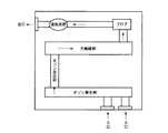
例えば、図3はオゾンと光触媒とを併用した空気清浄器の平面図である。被処理流体である空気の流路の上流から下流へ向けて、順にフィルタ部、オゾン発生部、光触媒装置および活性炭部を備え光触媒装置は空気の流路を形成するケース部材と、ケース部材の内部に設けられた多数の空孔を有する基体に光触媒機能層を担持させてなる光触媒フィルタと、光触媒フィルタを照射する紫外線照射手段とを有し、処理される空気の全量が光触媒フィルタを透過して流れるように光触媒フィルタが配置されている(例えば、特許文献1参照。)。 For example, FIG. 3 is a plan view of an air cleaner using ozone and a photocatalyst together. A filter member, an ozone generation unit, a photocatalyst device, and an activated carbon unit in order from the upstream to the downstream of the flow path of the air that is the fluid to be treated, the photocatalyst device forming a flow path for the air, and the interior of the case member A photocatalytic filter in which a photocatalytic functional layer is supported on a substrate having a large number of holes, and an ultraviolet irradiation means for irradiating the photocatalytic filter, and the entire amount of air to be processed passes through the photocatalytic filter. A photocatalytic filter is disposed so as to flow (see, for example, Patent Document 1).
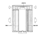
また、図4は活性炭、ゼオライトの少なくとも1種を含む吸着剤と光触媒とを併用した空気浄化装置の縦断面図である。光触媒を含む筒状の脱臭フィルタと、脱臭フィルタの上流側に脱臭フィルタに近接して励起光源を配置するとともに、脱臭フィルタを励起光源からの光の照射位置が変化するように回転させる構成とすることにより、脱臭フィルタ全体に吸着したガスを処理分解することができるので脱臭フィルタの再生率を向上させることができ、初期の優れた性能を長期間持続させる構成となっている(例えば、特許文献2参照。)。 FIG. 4 is a vertical cross-sectional view of an air purifying apparatus using an adsorbent containing at least one of activated carbon and zeolite and a photocatalyst. A cylindrical deodorizing filter including a photocatalyst, and an excitation light source disposed in the vicinity of the deodorizing filter on the upstream side of the deodorizing filter, and the deodorizing filter is rotated so that the irradiation position of the light from the excitation light source changes. Therefore, the gas adsorbed on the entire deodorizing filter can be processed and decomposed, so that the regeneration rate of the deodorizing filter can be improved and the initial excellent performance is maintained for a long period of time (for example, patent document) 2).
前記のように光触媒にバンドギャップ以上のエネルギーを持つ光を照射すると、光触媒の価電子帯から伝導帯に電子が励起され、正孔、電子が生成し、この正孔及び励起電子が光触媒表面に拡散し、光触媒表面に吸着した有害ガスや光触媒表面に拡散してきた有害ガスと反応して無害化する。光触媒の中でも、酸化力の強さ、化学的安定性に優れる等の理由から酸化チタン光触媒が最も多く利用されている。酸化チタン光触媒は、約400nm以下の波長の光を吸収することで前記のような光触媒反応が進行する。
一方、光触媒反応は光触媒の表面あるいは光触媒の表面付近でのみ進行する。このため、ppmまたはppbレベルの極めて希薄な濃度の有害ガスを光触媒により分解浄化する場合には、有害ガスが光触媒表面に拡散する過程が分解浄化反応の律速段階となりやすい。特に、光触媒に対しての吸着性が小さい有害ガスを分解浄化の対象とする場合には、分解浄化速度が顕著に遅くなるという問題がある。 On the other hand, the photocatalytic reaction proceeds only on the surface of the photocatalyst or in the vicinity of the surface of the photocatalyst. For this reason, when decomposing and purifying an extremely dilute harmful gas of ppm or ppb level with a photocatalyst, the process of diffusing the harmful gas on the surface of the photocatalyst tends to be the rate-limiting step of the decomposition and purification reaction. In particular, when a harmful gas having low adsorptivity to the photocatalyst is targeted for decomposition and purification, there is a problem that the decomposition and purification rate is remarkably slowed.
この点について、前記特許文献1においては、オゾンとの併用が示されているが、オゾンとの併用による浄化遠度の向上は必ずしも明確にされていない。 With regard to this point, Patent Document 1 discloses the combined use with ozone, but the improvement of the purification distance by the combined use with ozone is not necessarily clarified.
また、前記特許文献2においては、光触媒の他に、活性炭、ゼオライトのうち少なくとも1種を含む吸着剤との併用が記載されているが、吸着剤では吸着飽和に達した後には浄化作用がなくなり、吸着剤の交換が必要となる。使用済みの吸着剤は一般廃棄物や産業廃棄物となり、廃棄物増加の点から問題があった。 Moreover, in the said patent document 2, although combined use with the adsorption agent containing at least 1 sort (s) among activated carbon and a zeolite other than a photocatalyst is described, after an adsorption saturation is reached | attained in an adsorption agent, a purification effect is lost. The adsorbent must be replaced. The used adsorbent has become a general waste and an industrial waste, which has a problem in terms of an increase in waste.
本発明は、かかる事情に鑑みなされたもので、その目的は、上記課題を解決した、廃棄物量が少なく有害物質の分解除去効率の高い有害物質の分解技術を提供することにある。 The present invention has been made in view of such circumstances, and an object of the present invention is to provide a technology for decomposing harmful substances that solves the above-described problems and has a small amount of waste and high decomposition and removal efficiency of harmful substances.
上記課題を解決するため、光触媒を塗布したセラミックフィルタ等の光触媒を担持した部材と光触媒反応を励起するための光源を組み合わせ、光源からの光が外部に漏れないように、例えば、2枚のセラミックフィルタ等の光触媒を担持した部材の間に光源を配置し、臭気ガス等の有害物質を含んだ空気がセラミックフィルタ等の光触媒を担持した部材の光照射強度が最も高い面を最初に通過するように、2枚セラミックフィルタ等の光触媒を担持した部材の間に気体を導入してからセラミックフィルタ等の光触媒を担持した部材を通過させるようにする。 In order to solve the above-mentioned problems, a member supporting a photocatalyst such as a ceramic filter coated with a photocatalyst is combined with a light source for exciting a photocatalytic reaction, so that light from the light source does not leak outside, for example, two ceramics A light source is arranged between members carrying a photocatalyst such as a filter so that air containing harmful substances such as odor gas first passes through the surface with the highest light irradiation intensity of the member carrying the photocatalyst such as a ceramic filter. In addition, the gas is introduced between the members carrying the photocatalyst such as the two ceramic filters, and then the member carrying the photocatalyst such as the ceramic filter is allowed to pass through.
その理由は、通常、住空間で発生する匂い物質の濃度はppbから数ppmのオーダーであり、このような希薄濃度のガスを分解する場合には、ガスの分解速度はガス濃度に比例して大きくなることが知られている。また、光強度と分解速度の関係においても、通常、ブラックライトや光触媒用の冷陰極ランフから発せられる数mW/cm2オーダーの光強度の場合には、光強度が強いほど分解速度が高くなる。これらのことから、光強度およびガス濃度が強いほど分解速度が高くなり、脱臭効果等の有害物質除去効果が強くなることが帰結される。従って、光触媒を塗布したセラミックフィルタ等の光触媒を担持した部材と光源から構成される脱臭装置等の有害物質の分解装置においては、臭気ガス等の有害物質を含んだ空気がセラミックフィルタ等の光触媒を担持した部材の光源側の面から流入するような配置にすることで、臭気ガス等の有害物質を含んだ空気は、ガス濃度の最も高い状態で光強度の最も高いセラミックフィルタ等の光触媒を担持した部材面を通過して接触することになるので、反応効率を最も高くすることが可能となる。 The reason is usually that the concentration of odorous substances generated in the living space is on the order of several ppm from ppb, and when decomposing such a dilute gas, the gas decomposition rate is proportional to the gas concentration. It is known to grow. Also, regarding the relationship between the light intensity and the decomposition rate, in the case of light intensity of several mW / cm 2 order usually emitted from a cold cathode lamp for black light or photocatalyst, the decomposition rate increases as the light intensity increases. . From these facts, it can be concluded that the stronger the light intensity and the gas concentration, the higher the decomposition rate and the stronger the harmful substance removing effect such as the deodorizing effect. Therefore, in a decomposing apparatus for harmful substances such as a deodorizing device composed of a light source and a member supporting a photocatalyst such as a ceramic filter coated with a photocatalyst, air containing a harmful substance such as odorous gas is used as a photocatalyst such as a ceramic filter. Arranged to flow from the light source side surface of the supported member, air containing harmful substances such as odorous gas carries a photocatalyst such as a ceramic filter with the highest light intensity in the highest gas concentration. Therefore, the reaction efficiency can be maximized.
さらに、光触媒に照射された光は、その全てが光触媒に吸収され反応に寄与するのではなく、光の一部または大部分は光触媒層で反射して外部へ漏れていく。外部に漏れた光は脱臭反応に寄与できなくなるので、その分だけエネルギーが無駄に消費されることになる。このような消費をできるだけ少なくするため、光源からの光が外部に漏れにくくなるような構造をとることが必要になる。その一つの方法として、例えば、光源を2枚のセラミックフィルタ等の光触媒を担持した部材で挟み込んだ配置とする方法がある。光源を2枚のセラミックフィルタ等の光触媒を担持した部材で挟み込むことで、片方のセラミックフィルタ等の光触媒を担持した部材で反射して光は反対側のセラミックフィルタ等の光触媒を担持した部材に入射することになり、その表面にコートされた光触媒上で光触媒反応を進行させるのに利用することができ光の利用効率を高くすることが可能となる。 Furthermore, all of the light irradiated to the photocatalyst is absorbed by the photocatalyst and does not contribute to the reaction, but part or most of the light is reflected by the photocatalyst layer and leaks to the outside. Since the light leaked to the outside cannot contribute to the deodorization reaction, energy is wasted correspondingly. In order to minimize such consumption, it is necessary to adopt a structure that makes it difficult for light from the light source to leak to the outside. As one of the methods, for example, there is a method in which a light source is disposed between two members carrying a photocatalyst such as a ceramic filter. By sandwiching the light source between two ceramic filter-carrying members carrying a photocatalyst, the light is reflected by a member carrying a photocatalyst such as a ceramic filter, and the light is incident on a member carrying a photocatalyst such as a ceramic filter on the opposite side. Therefore, it can be used for advancing the photocatalytic reaction on the photocatalyst coated on the surface of the photocatalyst, so that the light use efficiency can be increased.
これらは以下に示すようにして具体的に実現できる。 These can be concretely realized as shown below.
請求項1に記載の有害物質の分解方法は、光触媒を担持した部材の表面同士を当該表面に照射された光が他の前記表面に反射するように配置し、これらの表面に囲まれる領域に設置した光源により前記光触媒を光照射して当該光触媒により有害物質を分解することを特徴とする。 In the method for decomposing a harmful substance according to claim 1, the surfaces of the members carrying the photocatalyst are arranged so that the light irradiated on the surfaces is reflected on the other surfaces, and the regions surrounded by these surfaces are arranged. The photocatalyst is irradiated with light by an installed light source, and harmful substances are decomposed by the photocatalyst.
請求項2に記載の有害物質の分解方法は、光触媒を担持した部材の表面同士を対向配置し、これらの表面間に設置した光源により前記光触媒を光照射して当該光触媒により有害物質を分解することを特徴とする。 The method for decomposing a harmful substance according to claim 2 comprises disposing the surfaces of the members carrying the photocatalyst opposite to each other, and irradiating the photocatalyst with a light source installed between these surfaces to decompose the harmful substance with the photocatalyst. It is characterized by that.
請求項3に記載の有害物質の分解方法は、光触媒を担持した筒状部材の内部に光源を設置して、当該光源により前記光触媒を光照射して当該光触媒により有害物質を分解することを特徴とする。
The method for decomposing a harmful substance according to
請求項4に記載の有害物質の分解方法は、請求項1〜3において、前記光触媒を担持した部材または筒状部材がフィルタ状または多孔質その他の気体を通過させることができる部材であることを特徴とする。
The method for decomposing a harmful substance according to
請求項5に記載の有害物質の分解方法は、請求項1〜4において、有害物質を含有する気体が前記光触媒を担持した部材または筒状部材の光照射強度が最も高い面を最初に通過するように前記気体を前記光触媒を担持した部材または筒状部材に導入することを特徴とする。
The method for decomposing a harmful substance according to
請求項6に記載の有害物質の分解方法は、請求項1〜5において、前記光触媒を担持した部材または筒状部材がセラミックであることを特徴とする。 According to a sixth aspect of the present invention, there is provided a method for decomposing a harmful substance according to any one of the first to fifth aspects, wherein the member carrying the photocatalyst or the cylindrical member is ceramic.
請求項7に記載の有害物質分解装置は、前記請求項1〜6いずれか1項に記載の有害物質の分解方法により有害物質を分解することを特徴とする。 A hazardous substance decomposition apparatus according to a seventh aspect is characterized in that the harmful substance is decomposed by the method for decomposing a harmful substance according to any one of the first to sixth aspects.
請求項8に記載の有害物質分解装置は、請求項7において、前記有害物質分解装置内の気体の流路に整流板を設置したことを特徴とする。
The harmful substance decomposition apparatus according to claim 8 is characterized in that, in
請求項1においては、光触媒を担持した部材の表面に照射された光は光触媒反応に寄与するか、反射したとしても他の光触媒を担持した部材の表面に照射されることになるため光エネルギーの利用効率を向上させることができる。 In claim 1, the light irradiated on the surface of the member carrying the photocatalyst contributes to the photocatalytic reaction or is reflected on the surface of the member carrying the other photocatalyst. Utilization efficiency can be improved.
請求項2においては、請求項1と同様の作用を奏するが、請求項2では光触媒を担持した部材の表面同士を対向配置させている。 In Claim 2, although the effect | action similar to Claim 1 is show | played, in Claim 2, the surface of the member which carry | supported the photocatalyst is opposingly arranged.
請求項3においては、請求項1と同様の作用を奏するが、請求項2では筒状部材を用いている。
In
請求項4においては、フィルタ状または多孔質その他の気体を通過させることができる部材を用いており、有害物質はこの部材を通過するときに分解除去される。また、多孔質を用いた場合には、部材の表面積が大きくなるので光触媒の存在量も大きくなり有害物質の分解除去効率が増大する。なお、フィルタ状または多孔質の部材以外のものでも、有害物質が通過できるものであれば本発明に適用できる。 According to a fourth aspect of the present invention, a member that can pass a filter-like, porous or other gas is used, and harmful substances are decomposed and removed when passing through this member. Further, when a porous material is used, the surface area of the member is increased, so that the amount of the photocatalyst is increased and the decomposition and removal efficiency of harmful substances is increased. It should be noted that other than the filter-like or porous member can be applied to the present invention as long as it can pass harmful substances.
請求項5においては、有害物質を含有する気体が前記光触媒を担持した部材または筒状部材の光照射強度が最も高い面を最初に通過するように前記気体を前記光触媒を担持した部材または筒状部材に導入するので、効率よく有害物質を分解除去することができる。
6. The member or cylinder carrying the photocatalyst according to
請求項6においては、水洗浄による性能回復が可能となり、フィルタ交換が不要となる。 According to the sixth aspect of the present invention, it is possible to recover the performance by washing with water, and it is not necessary to replace the filter.
請求項7においては、前記請求項1〜6により有害物質を分解除去できる装置を実現できる。 According to the seventh aspect, an apparatus capable of decomposing and removing harmful substances can be realized by the first to sixth aspects.
請求項8においては、整流板を取り付けることで、空気の流通抵抗が大きくなり、空気流量が少ない場合でも光触媒を担持した部材全体に空気を流通させることができ、有害物質と光触媒との接触効率が高くなり、有害物質の分解除去効果を向上させることができる。 According to the eighth aspect of the present invention, the flow resistance of the air is increased by attaching the current plate, and even when the air flow rate is small, the air can be circulated through the entire member carrying the photocatalyst, and the contact efficiency between the harmful substance and the photocatalyst. And the effect of decomposing and removing harmful substances can be improved.
本発明によれば、光触媒を用いた有害物質分解において、光エネルギーの利用率を高くすることができ、同時に有害物質分解効率を高くすることができる。 According to the present invention, in the harmful substance decomposition using the photocatalyst, the utilization rate of light energy can be increased, and at the same time, the harmful substance decomposition efficiency can be increased.
また、コンパクトで高性能な有害物質の分解装置を提供することができる。 In addition, a compact and high-performance hazardous substance decomposition apparatus can be provided.
さらに、フィルタの交換が不要で廃棄物のない有害物質の分解方法および装置を提供することができる。 Furthermore, it is possible to provide a method and an apparatus for decomposing harmful substances that do not require filter replacement and are free from waste.
(第1実施形態)
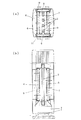
図1に第1実施形態に用いる脱臭装置の構成図を示す。図1において、(a)は断面図で、(b)は側面図である。
(First embodiment)
The block diagram of the deodorizing apparatus used for FIG. 1 at 1st Embodiment is shown. In FIG. 1, (a) is a sectional view and (b) is a side view.
この脱臭装置は、光触媒を塗布したセラミックフィルタと光触媒反応を励起させるための光源を組合せて、光源からの光が外部に漏れないように2枚のセラミックフィルタ間に光源を配置し、臭気ガスを含んだ空気がセラミックフィルタの光照射強度が最も高い面を最初に通過するように2枚のセラミックフィルタの間に気体を導入してからセラミックフィルタを通過する構造を持つ。 This deodorizing apparatus combines a ceramic filter coated with a photocatalyst and a light source for exciting a photocatalytic reaction, and arranges a light source between two ceramic filters so that light from the light source does not leak to the outside. It has a structure in which a gas is introduced between two ceramic filters and then passes through the ceramic filter so that the contained air first passes through the surface of the ceramic filter having the highest light irradiation intensity.
具体的には、図1に示すように、脱臭装置の下部に設置された気体を導入する吸気口1と、吸気口1の上部に設置された気体導入の駆動力であるファン2と、脱臭装置内において縦に平行に設置された光源である複数のランプ3と、このランプ3を挟むようにして設置された2枚のセラミックフィルタ4、5と、セラミックフィルタ4、5のに隣接された側室6、7と、この側室6、7と接続しており気体を排気口に導入するための側室8、9と、この側室8、9に接続しており気体を排気するための排気口10、11とを有している。
Specifically, as shown in FIG. 1, an intake port 1 for introducing a gas installed in the lower part of the deodorizing device, a fan 2 that is a driving force for introducing the gas installed in the upper part of the intake port 1, and a deodorization In the apparatus, a plurality of
この脱臭装置においてファン2を駆動させると吸気口1から気体が導入されて光源であるランプ3が設置された脱臭装置の中央部に到達する。そしてランプ3の両端のセラミックフィルタ4、5を通過するが、この通過の際にセラミックフィルタ4、5表面の光照射された光触媒と接触して空気中の臭気成分ガスが分解される。セラミックフィルタ4、5を通過して臭気成分ガスが分解除去された空気は側室6、7を経て側室8、9に至り、排気口10、11から排気される。
When the fan 2 is driven in this deodorizing apparatus, gas is introduced from the air inlet 1 and reaches the center of the deodorizing apparatus in which the
なお、光源であるランプ3はセラミックフィルタ4、5を均一に光照射できれば縦に平行に設置されてなくてもよく、複数ではなく1個でもよい。
Note that the
また、セラミックフィルタに塗布する光触媒には酸化チタンが最も好ましいが、酸化亜鉛、チタン酸ストロンチウム、チタン酸バリウム、またはこれらの光触媒を適宜組み合わせた化合物等、光触媒機能を有するものを使用することができる。 The photocatalyst to be applied to the ceramic filter is most preferably titanium oxide, but those having a photocatalytic function such as zinc oxide, strontium titanate, barium titanate, or a combination of these photocatalysts can be used. .
また、セラミックフィルタは2枚に限定されるものではなく、照射された光が他のセラミックフィルタに反射されるような位置関係であれば何枚でも設置してよい。その他にも、円筒状などの筒状のセラミックフィルタの内部に光源のランプ3を設置してもよい。
Further, the number of ceramic filters is not limited to two, and any number may be installed as long as the irradiated light is reflected by other ceramic filters. In addition, the
(第2実施形態)
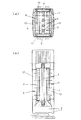
図2に第2実施形態に用いる脱臭装置の構成図を示す。図1において、(a)は断面図で、 (b)は側面図である。
(Second embodiment)
The block diagram of the deodorizing apparatus used for FIG. 2 at 2nd Embodiment is shown. In FIG. 1, (a) is a sectional view and (b) is a side view.
この脱臭装置は前記第1実施形態の脱臭装置において、側室6、7に整流板12を上方に移動する空気に対して垂直になるように複数枚取り付けたものである。
In the deodorizing apparatus of the first embodiment, a plurality of deodorizing apparatuses are attached to the
この整流板12を取り付けることで、空気の流通抵抗が大きくなり、空気流量が少ない場合でも側室6、7に均一に空気が流れるようにすることができる。この作用によりセラミックフィルタ4、5全体に空気を流通させることができ、臭気成分ガスと光触媒との接触効率が高くなり、脱臭効果を向上させることができる。
By attaching the
なお、整流板12は、上記の効果を得ることが出来きるものであれば、上方に移動する空気に対して垂直でなくてもよく、また、各側室6、7に一枚ずつでもよい。
Note that the
1…吸気口
2…ファン
3…ランプ
4…セラミックフィルタ
5…セラミックフィルタ
6…側室
7…側室
8…側室
9…側室
10…排気口
11…排気口
12…整流板
DESCRIPTION OF SYMBOLS 1 ... Intake port 2 ...
Claims (8)
Priority Applications (8)
| Application Number | Priority Date | Filing Date | Title |
|---|---|---|---|
| JP2004118499A JP2005296859A (en) | 2004-04-14 | 2004-04-14 | Harmful substance decomposition method and harmful substance decomposition apparatus |
| KR1020097001226A KR20090012284A (en) | 2004-04-14 | 2005-03-30 | Hazardous Substance Decomposition |
| CN200580011122XA CN1960769B (en) | 2004-04-14 | 2005-03-30 | Method and apparatus for decomposing harmful substance |
| PCT/JP2005/006159 WO2005099778A1 (en) | 2004-04-14 | 2005-03-30 | Method for decomposing harmful substance and apparatus for decomposing harmful substance |
| KR1020067021319A KR20060135884A (en) | 2004-04-14 | 2005-03-30 | Hazardous substance decomposition method and hazardous substance decomposition device |
| KR1020087020329A KR100930837B1 (en) | 2004-04-14 | 2005-03-30 | Hazardous Substance Decomposition |
| HK07106073.0A HK1101361B (en) | 2004-04-14 | 2005-03-30 | Method for decomposing harmful substance and apparatus for decomposing harmful substance |
| TW094111597A TW200539900A (en) | 2004-04-14 | 2005-04-13 | De composition method of harmful substances and decomposition device of harmful substances |
Applications Claiming Priority (1)
| Application Number | Priority Date | Filing Date | Title |
|---|---|---|---|
| JP2004118499A JP2005296859A (en) | 2004-04-14 | 2004-04-14 | Harmful substance decomposition method and harmful substance decomposition apparatus |
Publications (1)
| Publication Number | Publication Date |
|---|---|
| JP2005296859A true JP2005296859A (en) | 2005-10-27 |
Family
ID=35149787
Family Applications (1)
| Application Number | Title | Priority Date | Filing Date |
|---|---|---|---|
| JP2004118499A Pending JP2005296859A (en) | 2004-04-14 | 2004-04-14 | Harmful substance decomposition method and harmful substance decomposition apparatus |
Country Status (5)
| Country | Link |
|---|---|
| JP (1) | JP2005296859A (en) |
| KR (3) | KR100930837B1 (en) |
| CN (1) | CN1960769B (en) |
| TW (1) | TW200539900A (en) |
| WO (1) | WO2005099778A1 (en) |
Cited By (2)
| Publication number | Priority date | Publication date | Assignee | Title |
|---|---|---|---|---|
| FR2942965A1 (en) * | 2009-03-16 | 2010-09-17 | Biowind | Air treatment device for purification of air, has catalyst arranged on secondary creation unit, where secondary creation unit distinct from primary creation unit is traversed by air flow |
| CN110621353A (en) * | 2017-05-12 | 2019-12-27 | 首尔伟傲世有限公司 | Fluid treatment device |
Families Citing this family (6)
| Publication number | Priority date | Publication date | Assignee | Title |
|---|---|---|---|---|
| JP6052966B2 (en) * | 2012-08-31 | 2016-12-27 | 株式会社ニッキ | Gas filter device |
| KR101667235B1 (en) * | 2016-04-25 | 2016-10-18 | (주)유성엔비텍 | Offensive odor treatment apparatus |
| KR101705837B1 (en) * | 2016-10-20 | 2017-02-10 | 주식회사 포시 | An Air Purification Filter To Have The Sterilizing And Cleaning |
| KR102477937B1 (en) * | 2016-10-19 | 2022-12-15 | 삼성전자주식회사 | Photocatalyst filter and air conditioner including photocatalytic filter |
| WO2018074864A1 (en) | 2016-10-19 | 2018-04-26 | Samsung Electronics Co., Ltd. | Photocatalyst filter and air conditioner including the same |
| CN108889120A (en) * | 2018-07-24 | 2018-11-27 | 深圳市必发达科技有限公司 | Photocatalysis air purifying device |
Citations (3)
| Publication number | Priority date | Publication date | Assignee | Title |
|---|---|---|---|---|
| JPH1015351A (en) * | 1996-07-05 | 1998-01-20 | Takasago Thermal Eng Co Ltd | Catalyst for air purification and air purification device |
| JP2000210570A (en) * | 1999-01-26 | 2000-08-02 | Hitachi Ltd | Photocatalyst device |
| JP2003245660A (en) * | 2002-02-26 | 2003-09-02 | Meidensha Corp | Water treatment vessel |
Family Cites Families (3)
| Publication number | Priority date | Publication date | Assignee | Title |
|---|---|---|---|---|
| KR0153511B1 (en) * | 1995-12-29 | 1998-10-15 | 김태구 | Rigid mounting structure of car rocker panel |
| CN2339914Y (en) * | 1997-11-28 | 1999-09-22 | 中国科学院光电技术研究所 | Air purifying device |
| CN2361283Y (en) * | 1998-09-23 | 2000-02-02 | 中国建筑材料科学研究院 | Photocatalysis sterilizing and deodorant air purifying assembly |
-
2004
- 2004-04-14 JP JP2004118499A patent/JP2005296859A/en active Pending
-
2005
- 2005-03-30 CN CN200580011122XA patent/CN1960769B/en not_active Expired - Fee Related
- 2005-03-30 WO PCT/JP2005/006159 patent/WO2005099778A1/en not_active Ceased
- 2005-03-30 KR KR1020087020329A patent/KR100930837B1/en not_active Expired - Fee Related
- 2005-03-30 KR KR1020097001226A patent/KR20090012284A/en not_active Ceased
- 2005-03-30 KR KR1020067021319A patent/KR20060135884A/en not_active Ceased
- 2005-04-13 TW TW094111597A patent/TW200539900A/en unknown
Patent Citations (3)
| Publication number | Priority date | Publication date | Assignee | Title |
|---|---|---|---|---|
| JPH1015351A (en) * | 1996-07-05 | 1998-01-20 | Takasago Thermal Eng Co Ltd | Catalyst for air purification and air purification device |
| JP2000210570A (en) * | 1999-01-26 | 2000-08-02 | Hitachi Ltd | Photocatalyst device |
| JP2003245660A (en) * | 2002-02-26 | 2003-09-02 | Meidensha Corp | Water treatment vessel |
Cited By (2)
| Publication number | Priority date | Publication date | Assignee | Title |
|---|---|---|---|---|
| FR2942965A1 (en) * | 2009-03-16 | 2010-09-17 | Biowind | Air treatment device for purification of air, has catalyst arranged on secondary creation unit, where secondary creation unit distinct from primary creation unit is traversed by air flow |
| CN110621353A (en) * | 2017-05-12 | 2019-12-27 | 首尔伟傲世有限公司 | Fluid treatment device |
Also Published As
| Publication number | Publication date |
|---|---|
| CN1960769B (en) | 2010-05-12 |
| KR20090012284A (en) | 2009-02-02 |
| HK1101361A1 (en) | 2007-10-18 |
| KR20060135884A (en) | 2006-12-29 |
| WO2005099778A1 (en) | 2005-10-27 |
| CN1960769A (en) | 2007-05-09 |
| TW200539900A (en) | 2005-12-16 |
| KR20080080241A (en) | 2008-09-02 |
| KR100930837B1 (en) | 2009-12-10 |
Similar Documents
| Publication | Publication Date | Title |
|---|---|---|
| CN208018394U (en) | UV photolysis-adsorption integrated VOCs exhaust gas purification equipment | |
| JP2004512932A (en) | Method and apparatus for removing stench and volatile organic compounds from polluted gas | |
| CN201260930Y (en) | High efficiency air purifier | |
| CN207970701U (en) | A waste gas purification device | |
| KR101666621B1 (en) | Double dielectric barrier discharge plasma reactor, purification apparatus including the same, and purification method using the same | |
| CN206082107U (en) | Industry organic waste gas purification device | |
| KR101700269B1 (en) | Plasma catalyst adsorption purification apparatus capable of generating ozone and removing ozone and purification method using the same | |
| US20250090714A1 (en) | Plasma air purifying apparatus | |
| JP3180042U (en) | Air purification system | |
| JP2005296859A (en) | Harmful substance decomposition method and harmful substance decomposition apparatus | |
| JP2009513315A (en) | Equipment for purifying waste air containing harmful substances | |
| KR101005516B1 (en) | Odor treatment device and odor treatment method using corona discharge | |
| KR100807152B1 (en) | Filter of polluted air | |
| JP2002306587A (en) | Air purification device and air purification filter | |
| CN207970679U (en) | A waste gas purification device | |
| JP4923435B2 (en) | Hazardous substance treatment equipment | |
| CN103388859A (en) | All-dimensional inlet air purification device | |
| CN102614777A (en) | Photocatalytic oxidation treatment system of sludge odor and method for treating sludge odor by utilizing same | |
| CN210495927U (en) | Flue gas purification device with graphene fiber membrane | |
| CN203533722U (en) | All-direction air inlet air purification device | |
| CN101306205A (en) | Active composite catalyst air cleaning system | |
| HK1101361B (en) | Method for decomposing harmful substance and apparatus for decomposing harmful substance | |
| JP3714149B2 (en) | Air cleaner | |
| JP2006272034A (en) | Contaminating gas treatment apparatus and method using photocatalyst | |
| CN217287838U (en) | Photocatalytic synergistic purification device for complex exhaust gas treatment |
Legal Events
| Date | Code | Title | Description |
|---|---|---|---|
| A621 | Written request for application examination |
Free format text: JAPANESE INTERMEDIATE CODE: A621 Effective date: 20061114 |
|
| A131 | Notification of reasons for refusal |
Free format text: JAPANESE INTERMEDIATE CODE: A131 Effective date: 20091208 |
|
| A02 | Decision of refusal |
Free format text: JAPANESE INTERMEDIATE CODE: A02 Effective date: 20100406 |