JP3180042U - Air purification system - Google Patents
Air purification system Download PDFInfo
- Publication number
- JP3180042U JP3180042U JP2012005711U JP2012005711U JP3180042U JP 3180042 U JP3180042 U JP 3180042U JP 2012005711 U JP2012005711 U JP 2012005711U JP 2012005711 U JP2012005711 U JP 2012005711U JP 3180042 U JP3180042 U JP 3180042U
- Authority
- JP
- Japan
- Prior art keywords
- ozone
- gas
- light source
- zone
- area
- Prior art date
- Legal status (The legal status is an assumption and is not a legal conclusion. Google has not performed a legal analysis and makes no representation as to the accuracy of the status listed.)
- Expired - Fee Related
Links
Images


Abstract
【課題】空気清浄化システムを提供する。
【解決手段】本考案は、汚染物が含まれた気体を高度酸化作用区域とオゾン除去区域とに通過させ、高度酸化作用区域には、オゾン発生区域と光触媒区域とをさらに有し、オゾン除去区域には、オゾン除去網を有する。そのうち、オゾン発生区域には、オゾン発生装置を有し、光触媒区域には、二酸化チタン素子とUV光源素子とを有する。オゾン発生装置より生成されたオゾン分子と二酸化チタン素子の二酸化チタン分子は、UV光源素子のUV光源によって照射された後に、ヒドロキシルラジカルを生成して、生成されたヒドロキシルラジカルによって気体内の汚染物が酸化され、空気清浄化効果が達成される。
【選択図】図1An air cleaning system is provided.
The present invention allows a gas containing pollutants to pass through a highly oxidizing area and an ozone removing area, and the highly oxidizing area further includes an ozone generating area and a photocatalytic area, and ozone removing. The area has an ozone removal net. Among them, the ozone generation area has an ozone generator, and the photocatalyst area has a titanium dioxide element and a UV light source element. The ozone molecules generated from the ozone generator and the titanium dioxide molecules of the titanium dioxide element are irradiated with the UV light source of the UV light source element, and then generate hydroxyl radicals. Oxidized and air cleaning effect is achieved.
[Selection] Figure 1
Description
本考案は、空気清浄化システムに関し、光触媒装置と、オゾン装置によってヒドロキシルラジカルを生成して、それによって空気中の汚染物が酸化・分解され、空気清浄化効果を向上することができる、空気清浄化システムに関するものである。 The present invention relates to an air cleaning system, which generates hydroxyl radicals by a photocatalytic device and an ozone device, thereby oxidizing and decomposing contaminants in the air, thereby improving the air cleaning effect. Is related to the system.
周知のように、オゾンは、酸素の同素体であり、細胞膜のリポ蛋白、不飽和脂肪及び細胞外膜を破壊しまたは細胞の透過性を変化させることによって細胞の分裂を起こす。さらに、濃度が一定程度に達すると、細胞内部の蛋白酵素が破壊されると共に、微生物の繁殖が抑制され、ないし死滅する。このため、オゾンは空気清浄化用として広く利用されており、特にオゾンの持つ殺菌効果を活かして空気の清浄・脱臭が達成される。 As is well known, ozone is an allotrope of oxygen that causes cell division by destroying lipoproteins, unsaturated fats and the outer membrane of the cell membrane or changing the permeability of the cell. Further, when the concentration reaches a certain level, the protein enzyme inside the cell is destroyed and the propagation of microorganisms is suppressed or killed. For this reason, ozone is widely used for air purification, and air purification and deodorization are achieved by taking advantage of the bactericidal effect of ozone.
また、光触媒は、光化学反応の触媒であり、酸化還元力を提供する触媒である。
よって、空気清浄化の作業に良く使用される。常用の光触媒材料としては、リン化ガリウム(GaP)、ヒ化ガリウム(GaAs)、二酸化チタン(TiO2)などが挙げられる。中でも、二酸化チタンが、安価にかつ簡単に入手できるため、幅広く使用されている。
The photocatalyst is a catalyst for photochemical reaction and is a catalyst that provides redox power.
Therefore, it is often used for air cleaning work. Usable photocatalytic materials include gallium phosphide (GaP), gallium arsenide (GaAs), titanium dioxide (TiO2), and the like. Among these, titanium dioxide is widely used because it can be easily obtained at low cost.
中央式空気調和システムは、ビル内の空気の新陳代謝を調整する役割を担っている。しかし、空気品質が悪くなると、ビルの空気中における細菌などの汚染物は、人間の呼吸器に負担を与え、衰弱させる。その結果、呼吸器系の病気を発症することも稀ではない。従って、国民の健康を保護するため、室内空気品質管制法が施行されて、室内空気品質の改善対策が実施されている。また、製造メーカーより、数多くの異なる空気浄化技術が提供されている。 The central air conditioning system plays a role in regulating the metabolism of air in the building. However, when air quality deteriorates, contaminants such as bacteria in the building air can strain and weaken the human respiratory system. As a result, it is not uncommon to develop respiratory diseases. Therefore, in order to protect the health of the people, the Indoor Air Quality Control Law has been enforced and measures to improve indoor air quality are being implemented. In addition, many different air purification technologies are provided by manufacturers.
一般によく見かける浄化技術としては、オゾン、UV光源殺菌及び二酸化チタンを有する光触媒などの方式が挙げられる。そのうち、オゾンは、細菌の細胞膜外部のリポ蛋白を破壊することによって微生物を殺すと共に、空気中に含まれる臭気成分と有毒化学物質を分解することができる。しかし、実際に、純粋なオゾンの酸化能力は、従来周知されるものほど強くない。そのため、オゾンを直接に汚染物と接触する場合の反応速度が遅いため、清浄化効果がほとんどないという欠点がある。
さらに、単純なUV光源による殺菌では、その原理として、UV光源は、化学物質の分子結合を切断して化学構造を破壊することにより、空気清浄化の目的を達成することができる。しかし、実際に試験を行ったところ、切断された分子結合は、より複雑な構造に重合する可能性があるため、総揮発性有機化合物(total volatile organic compounds,TVOC)の測定値が本来低下するべきところが逆に上昇してしまう。
また、二酸化チタンを有する光触媒を単独に使用することでTVOCの濃度を低下させる効果があるが、空気調和設備が実際に運転する風速範囲において、その分解効率はまだ十分とは言えない。
Examples of purification techniques that are commonly seen include ozone, UV light source sterilization, and a photocatalyst having titanium dioxide. Among them, ozone kills microorganisms by destroying lipoproteins outside the cell membrane of bacteria, and can decompose odor components and toxic chemicals contained in the air. However, in fact, the oxidation capacity of pure ozone is not as strong as that known in the art. Therefore, there is a drawback that there is almost no cleaning effect because the reaction rate when ozone comes into direct contact with contaminants is slow.
Further, in the sterilization with a simple UV light source, as a principle, the UV light source can achieve the purpose of air purification by breaking the chemical structure by breaking the molecular bond of the chemical substance. However, when actually tested, since the broken molecular bond may polymerize to a more complicated structure, the measured value of total volatile organic compounds (TVOC) is inherently reduced. Conversely, the power should rise.
In addition, the use of a photocatalyst having titanium dioxide alone has the effect of reducing the concentration of TVOC, but its decomposition efficiency is still not sufficient in the wind speed range in which the air-conditioning equipment is actually operated.
そこで、本考案の考案者は、前述公知技術の不足点に鑑み、鋭意検討した結果、本考案の空気清浄化システムを考案した。 Then, the inventor of this invention devised the air purification system of this invention as a result of earnestly examining in view of the shortage of the said well-known technique.
本考案の主な目的は、安定した速度で空気中の汚染物を分解し、かつより良い空気清浄化能力を有する、空気清浄化システムを提供することにある。 The main object of the present invention is to provide an air cleaning system that decomposes contaminants in the air at a stable rate and has better air cleaning capability.
本考案の目的を達成するため、本考案の考案者は、汚染物が含まれた気体の通過を許容する空気清浄化システムを提案し、そのうち、前記気体が下記の入口、高度酸化作用区域、オゾン除去区域等の区域を順番に通過させるようにする。
高度酸化作用区域は、入口に接続していて、かつオゾンを発生するオゾン発生装置を有し、前記オゾン発生装置の紫外線により、酸素分子を切断してオゾンを生成するオゾン発生区域と、前記オゾン発生区域に接続していて、二酸化チタン素子と少なくとも一つのUV光源素子とを有し、前記オゾン発生装置のオゾン分子と前記二酸化チタン素子の二酸化チタン分子が、前記UV光源素子のUV光源によって照射された後に、ヒドロキシルラジカルを生成して、前記気体に対して高度酸化プロセス(advanced oxidation processes)を行うようにする光触媒区域と、を有する。
オゾン除去区域は、前記高度酸化作用区域に接続しており、前記光触媒区域の一側に設けられ、かつ出口に接続しているオゾン除去網を有し、前記オゾン除去網によってオゾンの流通速度を低下させ、分解されていないオゾン分子を前記UV光源素子によって切断し、酸化還元を行う。上述において、前記オゾン除去網は、活性炭素を有し、かつその厚さは少なくとも3センチメートルである。前記UV光源素子より出射する紫外線の波長範囲は、280nmから100nmまでの範囲内である。
In order to achieve the object of the present invention, the inventor of the present invention proposes an air cleaning system that allows the passage of a gas containing pollutants, in which the gas has the following inlet, an advanced oxidation area, Pass through areas such as ozone removal area in order.
The advanced oxidation zone has an ozone generator that is connected to the inlet and generates ozone, and the ozone generator zone that generates ozone by cutting oxygen molecules by the ultraviolet rays of the ozone generator; and the ozone A titanium dioxide element and at least one UV light source element are connected to the generation area, and the ozone molecule of the ozone generator and the titanium dioxide molecule of the titanium dioxide element are irradiated by the UV light source of the UV light source element. And a photocatalytic zone that generates hydroxyl radicals for advanced oxidation processes on the gas.
The ozone removal zone is connected to the advanced oxidation zone, has an ozone removal network provided on one side of the photocatalyst zone and connected to the outlet, and the ozone removal network controls the flow rate of ozone. Ozone molecules that are lowered and not decomposed are cleaved by the UV light source element, and oxidation-reduction is performed. In the above, the ozone removal screen has activated carbon and has a thickness of at least 3 centimeters. The wavelength range of the ultraviolet light emitted from the UV light source element is in the range from 280 nm to 100 nm.
また、本考案の空気清浄化システムは、前記高度酸化作用区域に内設され、かつ前記入口に接続していて、気体内の大きい粒子の汚染物を濾過できるアルミ製金属網と、前記オゾン発生区域に設けられるプラズマイオン発生装置と、前記オゾン除去網と前記出口との間に設けられるファンと、をさらに備え、前記プラズマイオン発生装置から電荷が放出され、前記気体が前記プラズマイオン発生装置を通過させる場合に、前記電荷のエネルギーによって水素正イオンと酸素負イオンを形成すると共に、発生されたプラズマイオン波により、前記気体内の汚染物を除去する。また、前記気体が通過する速度範囲は、0.6m/sから3m/sまでの範囲内である。 In addition, the air purification system of the present invention includes an aluminum metal net installed in the highly oxidizing area and connected to the inlet and capable of filtering contaminants of large particles in the gas, and the ozone generation. A plasma ion generator provided in an area; and a fan provided between the ozone removal network and the outlet, wherein electric charges are discharged from the plasma ion generator, and the gas passes through the plasma ion generator. When passing, hydrogen positive ions and oxygen negative ions are formed by the energy of the electric charge, and contaminants in the gas are removed by the generated plasma ion wave. Moreover, the speed range through which the gas passes is in the range from 0.6 m / s to 3 m / s.
後述する実験より、本考案の空気清浄化システムは高濃度において、活性炭素のように高速吸着はできないが、反応速度は安定しており、かつ室内空気品質の法基準を達成できるため、他の技術に比べて、本考案の空気清浄化システムはより良い空気清浄化能力を有する。 From the experiments described below, the air purification system of the present invention cannot perform high-speed adsorption like activated carbon at a high concentration, but the reaction rate is stable and can meet the legal standards for indoor air quality. Compared to technology, the air cleaning system of the present invention has better air cleaning capability.
本考案の空気清浄化システムをより完全に理解するために、以下、本考案の好適な実施例について添付図面を参照しながら詳細に説明する。 In order to more fully understand the air purification system of the present invention, preferred embodiments of the present invention will be described in detail below with reference to the accompanying drawings.
まず、本考案に係る実施例1について説明する。図1と図2は、それぞれ、本考案に係る実施例1の空気清浄化システムのブロック図と、本考案に係る実施例1の空気清浄化システムをハウジング内部に取り付ける態様図である。
これらの図を参照する。汚染物が含まれた気体の通過を許容する空気清浄化システムにおいて、前記気体が下記の入口21、高度酸化作用区域10(オゾン発生区域11と光触媒区域12を含む)、及びオゾン除去区域13等の区域を順番に通過させるようにする。入口21と、前記入口21に接続していて、かつオゾンを発生するオゾン発生装置111を有し、前記オゾン発生装置111の紫外線により、酸素分子を切断してオゾンを生成するオゾン発生区域11と、前記オゾン発生区域11に接続していて、二酸化チタン素子121と少なくとも一つのUV光源素子122と、を有し、前記オゾン発生装置111のオゾン分子と前記二酸化チタン素子121の二酸化チタン分子が、前期UV光源素子122のUV光源によって照射された後に、ヒドロキシルラジカルを生成して、前記気体に対して高度酸化プロセス(advanced oxidation processes)を行うようにする光触媒区域12と、を有する高度酸化作用区域10と、前記高度酸化作用区域10に接続しており、前記光触媒区域12の一側に設けられ、かつ出口22に接続しているオゾン除去網131を有し、前記オゾン除去網131によってオゾンの流通速度を低下させ、分解されていないオゾン分子を前記UV光源素子122によって切断し、酸化還元を行うオゾン除去区域13と、を備えるように構成される。
上述において、前記オゾン除去網131は、活性炭素を有し、かつその厚さは少なくとも3センチメートルである。前記UV光源素子122より出射する紫外線波長の範囲は、280nmから100nmまでの範囲内である。
First, a first embodiment according to the present invention will be described. FIGS. 1 and 2 are a block diagram of an air cleaning system according to a first embodiment of the present invention and an aspect diagram of mounting the air cleaning system according to the first embodiment of the present invention inside a housing, respectively.
Refer to these figures. In an air cleaning system that allows passage of a gas containing pollutants, the gas has the following
In the above description, the ozone removal net 131 has activated carbon and has a thickness of at least 3 centimeters. The range of the ultraviolet wavelength emitted from the UV
さらに、本考案の空気清浄化システムは、前記高度酸化作用区域10に内設され、かつ前記入口21に接続していて、気体内の大きい粒子の汚染物を濾過でき、大型異物を濾過するためのアルミ製金属網112と、前記オゾン発生区域11に設けられるプラズマイオン発生装置113と、前記オゾン除去網131と前記出口22との間に設けられるファン14と、をさらに備える。
前記プラズマイオン発生装置113から電荷が放出され、前記気体が前記プラズマイオン発生装置113を通過する場合に、前記電荷のエネルギーによって水素正イオンと酸素負イオンを形成すると共に、発生されたプラズマイオン波により、前記気体内の汚染物を除去する。
そのうち、前記ファン14の風速は、0.6m/sから3m/sまでの範囲内である。本考案にファンを設置する目的としては、気体が通過する速度を制御することにある。ただし、これは本考案の一実施態様にすぎず、本考案の実用新案登録請求の範囲を制限するものではない。気体が、大部分の空気調和システムに接続するパイプラインにおいて、いずれもすでに所定の流動速度を有する。そのため、気体の流動は、必ずしもファンに頼るわけではなく、気体が通過する速度範囲が、0.6m/sから3m/sまでの範囲内であれば、本考案は酸化還元を効率よく行うことができる。
Furthermore, the air cleaning system of the present invention is installed in the
When charges are released from the
Among them, the wind speed of the
本考案において、前記オゾン発生装置111より発生するオゾンが、光触媒区域12に到達した後、UV光源素子122が出射する紫外線がエネルギーを提供し、触媒はオゾンと反応すると、従来の光触媒技術に比べてはるかに多いヒドロキシルラジカル(Hydroxyl Radical)が生成される。
ヒドロキシルラジカルによる有機化合物の分解効率は、一般的なオゾンの109〜1010倍に達し、より強い酸化破壊能力を有する。よって、本考案において、オゾン発生の主な目的は、ヒドロキシルラジカルを生成して、高度酸化プロセス(Advanced Oxidation Processes, AOPs)を行い、自由基の強酸化力を利用して対象物である汚染物または中間生成物を破壊し、汚染物を二酸化炭素と水に分解ないし完全鉱化させるようにすることにより、空気清浄化の目的を達成する。
In the present invention, after the ozone generated from the
The decomposition efficiency of organic compounds by hydroxyl radical reaches 109 to 1010 times that of general ozone, and has a stronger oxidative destruction ability. Therefore, in the present invention, the main purpose of ozone generation is to generate hydroxyl radicals, perform advanced oxidation processes (AOPs), and use the strong oxidizing power of free groups as a target contaminant. Alternatively, the purpose of air purification is achieved by destroying intermediate products and allowing the contaminants to decompose or completely mineralize into carbon dioxide and water.
前述した技術は、空気清浄化の目的を効率的に達成することができるが、前述した技術のみでは、この技術を室内空間に適用することはできないのが実情である。
オゾン発生装置111より発生するオゾンが十分に利用されないため、入口22から室内空間に流入し、オゾンが急速に蓄積されてしまう。環境保護署(EPA)による室内空気品質の推奨値は、室内で許容できるオゾン濃度は、場所によって異なるように0.03〜0.05ppmであるため、本考案は、光触媒区域12の後側にオゾン除去網131を設けて、反応されていないオゾンを中和し、高度酸化プロセスの室内適用を可能にする。
Although the above-described technology can efficiently achieve the purpose of air purification, it is the actual situation that this technology cannot be applied to indoor spaces only with the above-described technology.
Since the ozone generated from the
引き続き、図3Aないし3Dは、それぞれ、本考案に係る風速と効率との関係を示す実験図である。これらの図を参照して説明する。本考案の配置は、特定の関連した運転パラメーターに合致しなければ、効率を最適化した状態までに発揮することができない。図3Aに示すように、光触媒による高度酸化プロセスの単位空気の分解効率は、風速が低いほど、反応効率が高くなり、性能も高くなる。しかし、室内空間に実際に適用する清浄化効果は、一回の分解効率によるものではなく、室内の総分解量によるものと考えられる。
また、室内の総分解量は、単位空気の分解効率と循環風量に関係する。図3Bに示すように、良好な状態にある総分解量に対応する一つの風速範囲が存在する。同様に、オゾンの発生量には類似した状況もある。図3Cに示すように、風速が速いほど、単位空気の発生するオゾンの量が高くなり、循環風量を加乗すると、総分解量に類似した状況がある。
オゾン除去網131の効率は、風速が速いほど、効率が低下されるため、システム全体としては、風速の増加につれてオゾン漏れの破過点(Break Throuth Point)が現れることが分かる。図3Dに示すように、漏れが始まると、室内環境にオゾンが蓄積し始める。よって、オゾン除去網131は、オゾン漏れの破過点の風速を最適な総分解性能の風速範囲以上にする必要がある。
3A to 3D are experimental diagrams showing the relationship between wind speed and efficiency according to the present invention. This will be described with reference to these drawings. The arrangement of the present invention cannot be achieved until the efficiency has been optimized unless certain relevant operating parameters are met. As shown in FIG. 3A, the unit air decomposition efficiency of the advanced oxidation process by the photocatalyst increases as the wind speed decreases, and the performance also increases. However, the cleaning effect actually applied to the indoor space is not due to the single decomposition efficiency, but is considered to be due to the total indoor decomposition amount.
The total amount of indoor decomposition is related to the decomposition efficiency of unit air and the circulation air volume. As shown in FIG. 3B, there is one wind speed range corresponding to the total amount of decomposition in a good state. Similarly, there are similar situations in the amount of ozone generated. As shown in FIG. 3C, the higher the wind speed, the higher the amount of ozone generated by the unit air, and there is a situation similar to the total decomposition amount when the circulating air volume is added.
Since the efficiency of the
前述の理由から、本考案の好ましい実施範囲として、前記ファン14の風速は、0.6 m/sec 〜 3 m/secの範囲とし、オゾン除去網131の厚さは、3cm以上にすることが好ましい。
For the above-mentioned reasons, as a preferable implementation range of the present invention, the wind speed of the
本考案において、オゾン除去網131は、活性炭素を除去装置のベースとすることができる。しかし、単純に活性炭素を使用するほか、例えば、活性炭素表面にアルカリ処理、酸化マンガン系触媒による改質またはその他のオゾン還元触媒による改質などのように、オゾン除去の効果を向上するために、活性炭素の表面に特殊処理を施して改質することができる。 In the present invention, the ozone removal net 131 can use activated carbon as the base of the removal device. However, in addition to simply using activated carbon, in order to improve the effect of ozone removal, such as alkali treatment on the activated carbon surface, reforming with a manganese oxide catalyst or reforming with other ozone reduction catalyst, etc. The surface of the activated carbon can be modified by applying a special treatment.
本考案の効果を検証するために、考案者は以下の試験を実施した。 In order to verify the effect of the present invention, the inventor conducted the following tests.
(実験方法)
考案者により6種類の実験を行った。アセトアルデヒド気体を汚染気体とし、10ppmのアセトアルデヒド気体を密閉箱体に注入した後、それぞれ紫外線灯管による照射、オゾン注入、光触媒、プラズマバー、活性炭素及び本考案の空気清浄化システムなどの方式を用いて密閉箱体の内部のアセトアルデヒド気体を除去し、かつ光イオン化検出器(photoionization detector,PID)で測定値を読み取る。
それぞれ、実験1は紫外線灯管による照射、実験2はオゾン注入、実験3は光触媒技術、実験4はプラズマバー、実験5は純活性炭素、そして、実験6は、本考案の空気浄化システム、を使用して行った。
(experimental method)
Six types of experiments were conducted by the inventor. After using acetaldehyde gas as a pollutant gas and injecting 10ppm of acetaldehyde gas into the sealed box, each system uses irradiation by ultraviolet lamp, ozone injection, photocatalyst, plasma bar, activated carbon, and air cleaning system of the present invention. The acetaldehyde gas inside the sealed box is removed, and the measured value is read with a photoionization detector (PID).
Experiment 1 is irradiation with an ultraviolet lamp tube, Experiment 2 is ozone injection, Experiment 3 is photocatalytic technology, Experiment 4 is a plasma bar, Experiment 5 is pure activated carbon, and Experiment 6 is an air purification system of the present invention. Done using.
(実験1)
図4は、アセトアルデヒドの分解に波長254nmの紫外線灯管を単独に使用した測定結果を示す図である。この図は、実験1において、密閉箱体の内部のアセトアルデヒド気体に波長254nmの紫外線を照射して実験を行った結果を示し、縦軸はTVOCの読み取り値、横軸は時間を表し、時間の単位は時間である。
公知技術において、紫外線で照射することによって微生物の細胞核の遺伝物質DNAから塩基の二量体構造が形成され、その二重らせん構造が破壊されて繁殖成長させないようになっている。しかし、実験1の図から分かるように、TVOCの読み取り値は、紫外線で照射した後に、それによるTVOCの上昇を示している。その原因は、紫外線には、結合を切断するエネルギーがあるものの、汚染物が切断された後、さらに大きい分子に再重合され、読み取り値が上昇してしまう。この点から、汚染物に対して紫外線灯管を単独に使用して照射しても空気中の汚染物を減少させることはできないことが分かる。
(Experiment 1)
FIG. 4 is a diagram showing a measurement result when an ultraviolet lamp having a wavelength of 254 nm is used alone for decomposing acetaldehyde. This figure shows the results of an experiment conducted by irradiating the acetaldehyde gas inside the sealed box with ultraviolet rays having a wavelength of 254 nm in Experiment 1, the vertical axis represents the TVOC reading, the horizontal axis represents the time, The unit is time.
In a known technique, a dimer structure of a base is formed from genetic material DNA of a cell nucleus of a microorganism by irradiation with ultraviolet rays, and the double helix structure is destroyed so that it does not grow and grow. However, as can be seen from the diagram of Experiment 1, the TVOC reading shows an increase in TVOC due to irradiation with ultraviolet light. The cause is that ultraviolet rays have energy to break bonds, but after the contaminants are cleaved, they are re-polymerized into larger molecules and the reading is increased. From this point, it is understood that the contaminants in the air cannot be reduced even if the contaminants are irradiated using an ultraviolet lamp tube alone.
(実験2)
図5は、アセトアルデヒドの分解にオゾンを単独に使用した測定結果を示す図である。この図は、実験2において、20ppmのオゾンを密閉箱体の内部に注入して実験を行った結果を示し、縦軸はTVOCの読み取り値、横軸は時間を表し、時間の単位は時間である。実験2に係る図から、オゾンでは空気中の汚染物を減少することはできないことが分かる。
(Experiment 2)
FIG. 5 is a diagram showing the results of measurement using ozone alone for the decomposition of acetaldehyde. This figure shows the result of performing an experiment by injecting 20 ppm of ozone into the closed box in Experiment 2, the vertical axis represents the TVOC reading, the horizontal axis represents time, and the unit of time is time. is there. From the diagram according to Experiment 2, it can be seen that ozone cannot reduce pollutants in the air.
(実験3)
図6は、アセトアルデヒドの分解に光触媒技術を単独に使用した測定結果を示す図である。実験1と実験2に比べて、光触媒技術では、空気中の化学物質を分解することは確実にできるが、分解の効率性は依然として一段低いので、実際に使用しても効果が現れなかった。
(Experiment 3)
FIG. 6 is a diagram showing the measurement results using the photocatalytic technique alone for the decomposition of acetaldehyde. Compared with Experiment 1 and Experiment 2, the photocatalytic technology can reliably decompose chemical substances in the air, but the efficiency of decomposition is still lower, so that even if it is actually used, no effect appears.
(実験4)
図7は、アセトアルデヒドの分解にプラズマバーを単独に使用した測定結果を示す図である。この図は、実験4において、イオンの個数が少なくとも1,236,000個/cc以上であるイオン化気体を発生するプラズマバーを密閉箱体の内部に取り付けて実験を行った結果を示し、縦軸はTVOCの読み取り値、横軸は時間を表し、時間の単位は時間である。
実験4に係る図から分かるように、その曲線は、実験2に類似したもので、プラズマは誘電体の放電によりオゾンを発生する働きしかしないもので、プラズマを用いて付加的な分解効果を生じることができないと推測されるため、プラズマバーは、空気中の汚染物を効率よく減少することができない。
(Experiment 4)
FIG. 7 is a diagram showing a measurement result using a plasma bar alone for decomposing acetaldehyde. This figure shows the result of an experiment conducted by attaching a plasma bar that generates ionized gas having the number of ions of at least 1,236,000 / cc in Experiment 4 to the inside of the sealed box. Represents the TVOC reading, the horizontal axis represents time, and the unit of time is time.
As can be seen from the diagram related to Experiment 4, the curve is similar to that of Experiment 2, and the plasma has only the function of generating ozone by the discharge of the dielectric, and causes an additional decomposition effect using the plasma. The plasma bar cannot efficiently reduce contaminants in the air because it is assumed that this is not possible.
(実験5)
図8は、アセトアルデヒドの分解に活性炭素を使用した測定結果を示す図である。この図において、縦軸はTVOCの読み取り値、横軸は時間を表し、時間の単位は時間である。実験5に係る図から分かるように、TVOCの濃度がより高くなるときに、吸着力濃度が強くなるが、濃度が6ppm以下に下がると、吸着力が劣化し、室内空気品質の推奨値は、3ppmであることから、活性炭素を単独に使用することでは空気中の汚染物を規定基準までに低下させることができない。
(Experiment 5)
FIG. 8 is a diagram showing the results of measurement using activated carbon for the decomposition of acetaldehyde. In this figure, the vertical axis represents TVOC readings, the horizontal axis represents time, and the unit of time is time. As can be seen from the graph relating to Experiment 5, when the concentration of TVOC becomes higher, the adsorptive power concentration becomes stronger. However, when the concentration decreases to 6 ppm or less, the adsorbing power deteriorates, and the recommended value of indoor air quality is Since it is 3 ppm, the pollutant in air cannot be reduced to a regulation standard by using activated carbon alone.
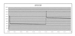
(実験6)
図9は、アセトアルデヒドの分解に本考案の空気清浄化システムを単独に使用した測定結果を示す図である。この図において、縦軸はTVOCの読み取り値、横軸は時間を表し、時間の単位は時間である。実験6に係る図から分かるように、TVOCの読み取り値が、実験を開始すると、急速に低下するようになり、30分もたたないうち、TVOCの読み取り値が最小値までに下げられ、上記の5つの実験に比べて、本考案の空気清浄化システムを適用すれば、アセトアルデヒドを効率よく分解することができる。すなわち、本考案の空気清浄化システムによれば、空気中の汚染物を効率よく減少できることが確認された。
(Experiment 6)
FIG. 9 is a diagram showing the results of measurement using the air purification system of the present invention alone for decomposing acetaldehyde. In this figure, the vertical axis represents TVOC readings, the horizontal axis represents time, and the unit of time is time. As can be seen from the diagram related to Experiment 6, when the experiment is started, the TVOC reading starts to decrease rapidly, and within 30 minutes, the TVOC reading is reduced to the minimum value. Compared to the five experiments, acetaldehyde can be efficiently decomposed by applying the air purification system of the present invention. That is, according to the air purification system of this invention, it was confirmed that the contaminant in the air can be reduced efficiently.
つまり、一般市販のプラズマバー及びオゾンによる空気清浄化の効果は良くないばかりでなく、オゾン濃度が高すぎて健康に支障をきたすおそれがある。紫外線灯管は、結合を切断する能力があるものの、結合が切断された汚染物の分子が、さらに大きい分子に再結合されため、紫外線灯管による空気中の化学物質の分解には、なお疑問が残っている。光触媒を単独に使用することで空気中の化学物質を分解できるが、その効率性は十分とは言えない。活性炭素は、空気中の汚染物を吸着できるが、物理吸着効果が限られており、6ppmに達すると、吸着力が著しく減殺される。そのため、工場などの汚染物濃度の高い環境のみに適用される。
以上に説明する実験より、本考案の空気清浄化システムは、高濃度の時に、活性炭素のように高速吸着することができないが、反応速度が安定しており、かつ室内空気品質の規定基準を満たすことができることから、他の技術に比べて、本考案の空気清浄化システムは、より良い空気清浄化の能力を有することは自明である。
That is, not only the effect of air cleaning by a commercially available plasma bar and ozone is not good, but there is a possibility that the ozone concentration is too high and may hinder health. Although UV lamps have the ability to break bonds, contaminant molecules with broken bonds are recombined into larger molecules, so there is still doubt about the breakdown of chemicals in the air by UV lamps. Remains. Although the chemical substance in the air can be decomposed by using the photocatalyst alone, its efficiency is not sufficient. Activated carbon can adsorb contaminants in the air, but its physical adsorption effect is limited, and when it reaches 6 ppm, the adsorptive power is remarkably reduced. Therefore, it is applied only to environments with high contaminant concentrations such as factories.
From the experiments described above, the air purification system of the present invention cannot adsorb at high speed like activated carbon at high concentrations, but the reaction rate is stable and the standard for indoor air quality is met. It is self-evident that the air purification system of the present invention has a better air purification capability than other technologies because it can be satisfied.
10 高度酸化作用区域
11 オゾン発生区域
111 オゾン発生装置
112 アルミ製金属網
113 プラズマイオン発生装置
12 光触媒区域
121 二酸化チタン素子
122 UV光源素子
13 オゾン除去区域
131 オゾン除去網
14 ファン
21 入口
22 出口
DESCRIPTION OF
Claims (6)
入口と、
前記入口に接続していて、かつ、オゾンを発生するオゾン発生装置を有し、前記オゾン発生装置の紫外線により、酸素分子を切断してオゾンを生成するオゾン発生区域と、前記オゾン発生区域に接続していて、二酸化チタン素子と少なくとも一つのUV光源素子とを有し、前記オゾン発生装置のオゾン分子と前記二酸化チタン素子の二酸化チタン分子が、前記UV光源素子のUV光源によって照射された後に、ヒドロキシルラジカルを生成して、前記気体に対して高度酸化プロセス(advanced oxidation processes)を行うようにする光触媒区域を有する高度酸化作用区域と、
前記高度酸化作用区域に接続しており、前記光触媒区域の一側に設けられ、かつ出口に接続しているオゾン除去網を有し、前記オゾン除去網によってオゾンの流通速度を低下させ、分解されていないオゾン分子を前記UV光源素子によって切断し、酸化還元を行うオゾン除去区域とを備え、
前記気体が前記入口と前記高度酸化作用区域と前記オゾン除去区域を順番に通過させるように構成したことを特徴とする、
空気清浄化システム。 An air cleaning system that allows the passage of gas containing contaminants,
The entrance,
Connected to the inlet and having an ozone generator for generating ozone, and generating ozone by cutting off oxygen molecules by ultraviolet rays of the ozone generator, and connected to the ozone generation area And having a titanium dioxide element and at least one UV light source element, and after the ozone molecules of the ozone generator and the titanium dioxide molecules of the titanium dioxide element are irradiated by the UV light source of the UV light source element, A highly oxidizing zone having a photocatalytic zone that generates hydroxyl radicals to effect advanced oxidation processes on the gas;
Connected to the advanced oxidation zone, and has an ozone removal network provided on one side of the photocatalyst zone and connected to the outlet. The ozone removal network reduces the flow rate of ozone and decomposes it. An ozone removal zone that cuts off ozone molecules by the UV light source element and performs oxidation-reduction,
The gas is configured to pass through the inlet, the high oxidation area, and the ozone removal area in order.
Air purification system.
Priority Applications (1)
| Application Number | Priority Date | Filing Date | Title |
|---|---|---|---|
| JP2012005711U JP3180042U (en) | 2012-09-19 | 2012-09-19 | Air purification system |
Applications Claiming Priority (1)
| Application Number | Priority Date | Filing Date | Title |
|---|---|---|---|
| JP2012005711U JP3180042U (en) | 2012-09-19 | 2012-09-19 | Air purification system |
Publications (1)
| Publication Number | Publication Date |
|---|---|
| JP3180042U true JP3180042U (en) | 2012-11-29 |
Family
ID=48006641
Family Applications (1)
| Application Number | Title | Priority Date | Filing Date |
|---|---|---|---|
| JP2012005711U Expired - Fee Related JP3180042U (en) | 2012-09-19 | 2012-09-19 | Air purification system |
Country Status (1)
| Country | Link |
|---|---|
| JP (1) | JP3180042U (en) |
Cited By (4)
| Publication number | Priority date | Publication date | Assignee | Title |
|---|---|---|---|---|
| CN107096362A (en) * | 2016-02-19 | 2017-08-29 | 杭州中兵环保股份有限公司 | Ozone oxidization combination cracking excites flue gas desulfurization and denitrification integrated apparatus and method |
| CN109893938A (en) * | 2018-12-21 | 2019-06-18 | 杜国栋 | A kind of device removing Radon |
| CN109908391A (en) * | 2018-12-21 | 2019-06-21 | 杜国栋 | A kind of hydroxyl radical free radical generation device |
| CN109908390A (en) * | 2018-12-21 | 2019-06-21 | 杜国栋 | A kind of device of cleaning and disinfecting air and body surface |
-
2012
- 2012-09-19 JP JP2012005711U patent/JP3180042U/en not_active Expired - Fee Related
Cited By (4)
| Publication number | Priority date | Publication date | Assignee | Title |
|---|---|---|---|---|
| CN107096362A (en) * | 2016-02-19 | 2017-08-29 | 杭州中兵环保股份有限公司 | Ozone oxidization combination cracking excites flue gas desulfurization and denitrification integrated apparatus and method |
| CN109893938A (en) * | 2018-12-21 | 2019-06-18 | 杜国栋 | A kind of device removing Radon |
| CN109908391A (en) * | 2018-12-21 | 2019-06-21 | 杜国栋 | A kind of hydroxyl radical free radical generation device |
| CN109908390A (en) * | 2018-12-21 | 2019-06-21 | 杜国栋 | A kind of device of cleaning and disinfecting air and body surface |
Similar Documents
| Publication | Publication Date | Title |
|---|---|---|
| KR101777209B1 (en) | Method and apparatus for air purification with function of formaldehyde removal and sterilization from indoor air | |
| KR20050102600A (en) | Plasma odor and germ remover | |
| KR101430120B1 (en) | Gas purification apparatus | |
| KR20130102045A (en) | A filter and device for treating air | |
| JP3180042U (en) | Air purification system | |
| KR101883062B1 (en) | Photocatalyst unit and air cleaning apparatus comprising the same | |
| CN114459104A (en) | Air purifying device | |
| KR100930837B1 (en) | Method for decomposing harmful substance | |
| KR20080057808A (en) | Odor gas treatment device having biochemical odor gas treatment unit | |
| JP5108492B2 (en) | Air purification method and air purification device | |
| CN111237920A (en) | Formaldehyde removal disinfection machine | |
| KR101005516B1 (en) | Odor removal device and method using corona discharge | |
| KR100949164B1 (en) | Photocatalytic reactor having a function of deodorization and sterilization air pollution and method of the same, and stand-alone a foul smell treatment apparatus using the same | |
| KR100428965B1 (en) | Air purification method | |
| KR100684924B1 (en) | Plasma odor and germ remover | |
| KR102033472B1 (en) | Plasma odor and germ remover | |
| CN112594842A (en) | Air purification method and device based on combination of filtration, sterilization and catalysis diversification | |
| JP3000056B2 (en) | Air purifier | |
| TWM457859U (en) | Air purifying system | |
| KR20210028878A (en) | Air clean system and clean method | |
| CN215765623U (en) | Photocatalysis purification disinfection and sterilization device | |
| JP3936876B2 (en) | Sterilization / deodorization equipment | |
| CN103388859A (en) | All-dimensional inlet air purification device | |
| CN103134117B (en) | A kind of electrical-conductive nanometer TiO 2composite photocatalyst air cleaning unit | |
| KR20190105823A (en) | Offensive odor treatment apparatus using dual UV ramp and adsorbent |
Legal Events
| Date | Code | Title | Description |
|---|---|---|---|
| R150 | Certificate of patent (=grant) or registration of utility model |
Free format text: JAPANESE INTERMEDIATE CODE: R150 |
|
| FPAY | Renewal fee payment (prs date is renewal date of database) |
Free format text: PAYMENT UNTIL: 20151107 Year of fee payment: 3 |
|
| LAPS | Cancellation because of no payment of annual fees |