JP2005296629A - Method and apparatus for cutaneous absorption enhancement and percutaneous drug delivery - Google Patents
Method and apparatus for cutaneous absorption enhancement and percutaneous drug delivery Download PDFInfo
- Publication number
- JP2005296629A JP2005296629A JP2005047835A JP2005047835A JP2005296629A JP 2005296629 A JP2005296629 A JP 2005296629A JP 2005047835 A JP2005047835 A JP 2005047835A JP 2005047835 A JP2005047835 A JP 2005047835A JP 2005296629 A JP2005296629 A JP 2005296629A
- Authority
- JP
- Japan
- Prior art keywords
- skin
- patient
- probe
- electrodes
- burst
- Prior art date
- Legal status (The legal status is an assumption and is not a legal conclusion. Google has not performed a legal analysis and makes no representation as to the accuracy of the status listed.)
- Withdrawn
Links
- 238000000034 method Methods 0.000 title claims abstract description 45
- 238000010521 absorption reaction Methods 0.000 title claims abstract description 36
- 238000012377 drug delivery Methods 0.000 title 1
- 239000000523 sample Substances 0.000 claims abstract description 166
- 239000000126 substance Substances 0.000 claims abstract description 74
- 238000011282 treatment Methods 0.000 claims abstract description 74
- 239000003814 drug Substances 0.000 claims abstract description 17
- 229940079593 drug Drugs 0.000 claims abstract description 15
- 210000003491 skin Anatomy 0.000 claims description 368
- 208000035484 Cellulite Diseases 0.000 claims description 17
- 206010049752 Peau d'orange Diseases 0.000 claims description 17
- 230000036232 cellulite Effects 0.000 claims description 17
- 239000007788 liquid Substances 0.000 claims description 16
- 239000006071 cream Substances 0.000 claims description 12
- 239000000499 gel Substances 0.000 claims description 11
- 230000001965 increasing effect Effects 0.000 claims description 11
- 239000000017 hydrogel Substances 0.000 claims description 7
- 210000000434 stratum corneum Anatomy 0.000 claims description 6
- 238000010792 warming Methods 0.000 claims description 6
- 210000000577 adipose tissue Anatomy 0.000 claims description 5
- 239000006210 lotion Substances 0.000 claims description 5
- 239000002184 metal Substances 0.000 claims description 5
- 206010040844 Skin exfoliation Diseases 0.000 claims description 3
- 238000010438 heat treatment Methods 0.000 claims description 3
- 238000002560 therapeutic procedure Methods 0.000 claims 4
- 208000035874 Excoriation Diseases 0.000 claims 2
- 239000003638 chemical reducing agent Substances 0.000 claims 1
- 230000010355 oscillation Effects 0.000 claims 1
- 230000000694 effects Effects 0.000 description 33
- 230000037384 skin absorption Effects 0.000 description 18
- 231100000274 skin absorption Toxicity 0.000 description 18
- 239000000463 material Substances 0.000 description 17
- 239000011148 porous material Substances 0.000 description 17
- 238000004804 winding Methods 0.000 description 16
- 239000003990 capacitor Substances 0.000 description 14
- 230000002093 peripheral effect Effects 0.000 description 10
- 230000000638 stimulation Effects 0.000 description 8
- FAPWRFPIFSIZLT-UHFFFAOYSA-M Sodium chloride Chemical compound [Na+].[Cl-] FAPWRFPIFSIZLT-UHFFFAOYSA-M 0.000 description 7
- CIWBSHSKHKDKBQ-JLAZNSOCSA-N Ascorbic acid Chemical compound OC[C@H](O)[C@H]1OC(=O)C(O)=C1O CIWBSHSKHKDKBQ-JLAZNSOCSA-N 0.000 description 6
- 102000008186 Collagen Human genes 0.000 description 6
- 108010035532 Collagen Proteins 0.000 description 6
- 229920001436 collagen Polymers 0.000 description 6
- 230000008878 coupling Effects 0.000 description 6
- 238000010168 coupling process Methods 0.000 description 6
- 238000005859 coupling reaction Methods 0.000 description 6
- 230000010339 dilation Effects 0.000 description 6
- 229920001971 elastomer Polymers 0.000 description 6
- 238000004520 electroporation Methods 0.000 description 6
- 239000004033 plastic Substances 0.000 description 6
- 229920003023 plastic Polymers 0.000 description 6
- 230000001360 synchronised effect Effects 0.000 description 6
- 239000011358 absorbing material Substances 0.000 description 5
- 230000008901 benefit Effects 0.000 description 5
- 238000010586 diagram Methods 0.000 description 5
- 230000036961 partial effect Effects 0.000 description 5
- NNJVILVZKWQKPM-UHFFFAOYSA-N Lidocaine Chemical compound CCN(CC)CC(=O)NC1=C(C)C=CC=C1C NNJVILVZKWQKPM-UHFFFAOYSA-N 0.000 description 4
- 239000003795 chemical substances by application Substances 0.000 description 4
- 230000002708 enhancing effect Effects 0.000 description 4
- 230000001939 inductive effect Effects 0.000 description 4
- 229960004194 lidocaine Drugs 0.000 description 4
- 239000011780 sodium chloride Substances 0.000 description 4
- 102000016942 Elastin Human genes 0.000 description 3
- 108010014258 Elastin Proteins 0.000 description 3
- 238000009825 accumulation Methods 0.000 description 3
- 239000002253 acid Substances 0.000 description 3
- 230000002411 adverse Effects 0.000 description 3
- 229960005070 ascorbic acid Drugs 0.000 description 3
- 235000010323 ascorbic acid Nutrition 0.000 description 3
- 239000011668 ascorbic acid Substances 0.000 description 3
- 239000004020 conductor Substances 0.000 description 3
- 230000007423 decrease Effects 0.000 description 3
- 230000003247 decreasing effect Effects 0.000 description 3
- 229920002549 elastin Polymers 0.000 description 3
- 238000002474 experimental method Methods 0.000 description 3
- 229960004393 lidocaine hydrochloride Drugs 0.000 description 3
- YECIFGHRMFEPJK-UHFFFAOYSA-N lidocaine hydrochloride monohydrate Chemical compound O.[Cl-].CC[NH+](CC)CC(=O)NC1=C(C)C=CC=C1C YECIFGHRMFEPJK-UHFFFAOYSA-N 0.000 description 3
- 230000007246 mechanism Effects 0.000 description 3
- -1 or an outer (eg Substances 0.000 description 3
- 230000010363 phase shift Effects 0.000 description 3
- 229920000742 Cotton Polymers 0.000 description 2
- 241000699670 Mus sp. Species 0.000 description 2
- 239000004743 Polypropylene Substances 0.000 description 2
- 230000002745 absorbent Effects 0.000 description 2
- 239000002250 absorbent Substances 0.000 description 2
- 230000009471 action Effects 0.000 description 2
- 210000001789 adipocyte Anatomy 0.000 description 2
- 238000004458 analytical method Methods 0.000 description 2
- 238000006243 chemical reaction Methods 0.000 description 2
- 230000003111 delayed effect Effects 0.000 description 2
- 230000001627 detrimental effect Effects 0.000 description 2
- 230000005684 electric field Effects 0.000 description 2
- 230000004048 modification Effects 0.000 description 2
- 238000012986 modification Methods 0.000 description 2
- 229920001155 polypropylene Polymers 0.000 description 2
- 230000009467 reduction Effects 0.000 description 2
- 230000002829 reductive effect Effects 0.000 description 2
- 230000000630 rising effect Effects 0.000 description 2
- YGSDEFSMJLZEOE-UHFFFAOYSA-N salicylic acid Chemical compound OC(=O)C1=CC=CC=C1O YGSDEFSMJLZEOE-UHFFFAOYSA-N 0.000 description 2
- 230000035807 sensation Effects 0.000 description 2
- 230000035945 sensitivity Effects 0.000 description 2
- 238000000926 separation method Methods 0.000 description 2
- 210000001519 tissue Anatomy 0.000 description 2
- 230000007704 transition Effects 0.000 description 2
- 206010028980 Neoplasm Diseases 0.000 description 1
- 239000004677 Nylon Substances 0.000 description 1
- 206010040880 Skin irritation Diseases 0.000 description 1
- 238000011298 ablation treatment Methods 0.000 description 1
- 239000002390 adhesive tape Substances 0.000 description 1
- 230000003444 anaesthetic effect Effects 0.000 description 1
- 239000002260 anti-inflammatory agent Substances 0.000 description 1
- 238000003491 array Methods 0.000 description 1
- 230000004888 barrier function Effects 0.000 description 1
- 201000011510 cancer Diseases 0.000 description 1
- 210000004027 cell Anatomy 0.000 description 1
- 210000000170 cell membrane Anatomy 0.000 description 1
- 230000008859 change Effects 0.000 description 1
- 229940110456 cocoa butter Drugs 0.000 description 1
- 235000019868 cocoa butter Nutrition 0.000 description 1
- 229960005188 collagen Drugs 0.000 description 1
- 238000011109 contamination Methods 0.000 description 1
- 208000030381 cutaneous melanoma Diseases 0.000 description 1
- 238000007599 discharging Methods 0.000 description 1
- 238000001647 drug administration Methods 0.000 description 1
- 238000005868 electrolysis reaction Methods 0.000 description 1
- 235000019197 fats Nutrition 0.000 description 1
- 229920002457 flexible plastic Polymers 0.000 description 1
- 230000006870 function Effects 0.000 description 1
- 230000006698 induction Effects 0.000 description 1
- 238000003780 insertion Methods 0.000 description 1
- 230000037431 insertion Effects 0.000 description 1
- 238000002955 isolation Methods 0.000 description 1
- 239000002502 liposome Substances 0.000 description 1
- 239000003589 local anesthetic agent Substances 0.000 description 1
- 230000000873 masking effect Effects 0.000 description 1
- 238000002483 medication Methods 0.000 description 1
- 210000004379 membrane Anatomy 0.000 description 1
- 230000003020 moisturizing effect Effects 0.000 description 1
- 229920001778 nylon Polymers 0.000 description 1
- 230000003287 optical effect Effects 0.000 description 1
- 230000008058 pain sensation Effects 0.000 description 1
- FJKROLUGYXJWQN-UHFFFAOYSA-N papa-hydroxy-benzoic acid Natural products OC(=O)C1=CC=C(O)C=C1 FJKROLUGYXJWQN-UHFFFAOYSA-N 0.000 description 1
- 208000035824 paresthesia Diseases 0.000 description 1
- 230000002285 radioactive effect Effects 0.000 description 1
- 230000002441 reversible effect Effects 0.000 description 1
- 229960004889 salicylic acid Drugs 0.000 description 1
- 231100000075 skin burn Toxicity 0.000 description 1
- 230000036556 skin irritation Effects 0.000 description 1
- 231100000475 skin irritation Toxicity 0.000 description 1
- 201000003708 skin melanoma Diseases 0.000 description 1
- 230000007928 solubilization Effects 0.000 description 1
- 238000005063 solubilization Methods 0.000 description 1
- 238000007920 subcutaneous administration Methods 0.000 description 1
- 238000012360 testing method Methods 0.000 description 1
Images


Classifications
-
- A—HUMAN NECESSITIES
- A61—MEDICAL OR VETERINARY SCIENCE; HYGIENE
- A61H—PHYSICAL THERAPY APPARATUS, e.g. DEVICES FOR LOCATING OR STIMULATING REFLEX POINTS IN THE BODY; ARTIFICIAL RESPIRATION; MASSAGE; BATHING DEVICES FOR SPECIAL THERAPEUTIC OR HYGIENIC PURPOSES OR SPECIFIC PARTS OF THE BODY
- A61H23/00—Percussion or vibration massage, e.g. using supersonic vibration; Suction-vibration massage; Massage with moving diaphragms
- A61H23/02—Percussion or vibration massage, e.g. using supersonic vibration; Suction-vibration massage; Massage with moving diaphragms with electric or magnetic drive
- A61H23/0254—Percussion or vibration massage, e.g. using supersonic vibration; Suction-vibration massage; Massage with moving diaphragms with electric or magnetic drive with rotary motor
- A61H23/0263—Percussion or vibration massage, e.g. using supersonic vibration; Suction-vibration massage; Massage with moving diaphragms with electric or magnetic drive with rotary motor using rotating unbalanced masses
-
- A—HUMAN NECESSITIES
- A61—MEDICAL OR VETERINARY SCIENCE; HYGIENE
- A61H—PHYSICAL THERAPY APPARATUS, e.g. DEVICES FOR LOCATING OR STIMULATING REFLEX POINTS IN THE BODY; ARTIFICIAL RESPIRATION; MASSAGE; BATHING DEVICES FOR SPECIAL THERAPEUTIC OR HYGIENIC PURPOSES OR SPECIFIC PARTS OF THE BODY
- A61H23/00—Percussion or vibration massage, e.g. using supersonic vibration; Suction-vibration massage; Massage with moving diaphragms
- A61H23/02—Percussion or vibration massage, e.g. using supersonic vibration; Suction-vibration massage; Massage with moving diaphragms with electric or magnetic drive
-
- A—HUMAN NECESSITIES
- A61—MEDICAL OR VETERINARY SCIENCE; HYGIENE
- A61H—PHYSICAL THERAPY APPARATUS, e.g. DEVICES FOR LOCATING OR STIMULATING REFLEX POINTS IN THE BODY; ARTIFICIAL RESPIRATION; MASSAGE; BATHING DEVICES FOR SPECIAL THERAPEUTIC OR HYGIENIC PURPOSES OR SPECIFIC PARTS OF THE BODY
- A61H39/00—Devices for locating or stimulating specific reflex points of the body for physical therapy, e.g. acupuncture
- A61H39/002—Using electric currents
-
- A—HUMAN NECESSITIES
- A61—MEDICAL OR VETERINARY SCIENCE; HYGIENE
- A61H—PHYSICAL THERAPY APPARATUS, e.g. DEVICES FOR LOCATING OR STIMULATING REFLEX POINTS IN THE BODY; ARTIFICIAL RESPIRATION; MASSAGE; BATHING DEVICES FOR SPECIAL THERAPEUTIC OR HYGIENIC PURPOSES OR SPECIFIC PARTS OF THE BODY
- A61H7/00—Devices for suction-kneading massage; Devices for massaging the skin by rubbing or brushing not otherwise provided for
- A61H7/007—Kneading
- A61H7/008—Suction kneading
-
- A—HUMAN NECESSITIES
- A61—MEDICAL OR VETERINARY SCIENCE; HYGIENE
- A61H—PHYSICAL THERAPY APPARATUS, e.g. DEVICES FOR LOCATING OR STIMULATING REFLEX POINTS IN THE BODY; ARTIFICIAL RESPIRATION; MASSAGE; BATHING DEVICES FOR SPECIAL THERAPEUTIC OR HYGIENIC PURPOSES OR SPECIFIC PARTS OF THE BODY
- A61H9/00—Pneumatic or hydraulic massage
- A61H9/005—Pneumatic massage
-
- A—HUMAN NECESSITIES
- A61—MEDICAL OR VETERINARY SCIENCE; HYGIENE
- A61N—ELECTROTHERAPY; MAGNETOTHERAPY; RADIATION THERAPY; ULTRASOUND THERAPY
- A61N1/00—Electrotherapy; Circuits therefor
- A61N1/02—Details
- A61N1/04—Electrodes
- A61N1/0404—Electrodes for external use
- A61N1/0408—Use-related aspects
- A61N1/0412—Specially adapted for transcutaneous electroporation, e.g. including drug reservoirs
- A61N1/0416—Anode and cathode
- A61N1/0424—Shape of the electrode
-
- A—HUMAN NECESSITIES
- A61—MEDICAL OR VETERINARY SCIENCE; HYGIENE
- A61N—ELECTROTHERAPY; MAGNETOTHERAPY; RADIATION THERAPY; ULTRASOUND THERAPY
- A61N1/00—Electrotherapy; Circuits therefor
- A61N1/02—Details
- A61N1/04—Electrodes
- A61N1/0404—Electrodes for external use
- A61N1/0472—Structure-related aspects
- A61N1/0476—Array electrodes (including any electrode arrangement with more than one electrode for at least one of the polarities)
-
- A—HUMAN NECESSITIES
- A61—MEDICAL OR VETERINARY SCIENCE; HYGIENE
- A61N—ELECTROTHERAPY; MAGNETOTHERAPY; RADIATION THERAPY; ULTRASOUND THERAPY
- A61N1/00—Electrotherapy; Circuits therefor
- A61N1/18—Applying electric currents by contact electrodes
- A61N1/20—Applying electric currents by contact electrodes continuous direct currents
- A61N1/30—Apparatus for iontophoresis, i.e. transfer of media in ionic state by an electromotoric force into the body, or cataphoresis
-
- A—HUMAN NECESSITIES
- A61—MEDICAL OR VETERINARY SCIENCE; HYGIENE
- A61N—ELECTROTHERAPY; MAGNETOTHERAPY; RADIATION THERAPY; ULTRASOUND THERAPY
- A61N1/00—Electrotherapy; Circuits therefor
- A61N1/18—Applying electric currents by contact electrodes
- A61N1/32—Applying electric currents by contact electrodes alternating or intermittent currents
- A61N1/325—Applying electric currents by contact electrodes alternating or intermittent currents for iontophoresis, i.e. transfer of media in ionic state by an electromotoric force into the body
-
- A—HUMAN NECESSITIES
- A61—MEDICAL OR VETERINARY SCIENCE; HYGIENE
- A61H—PHYSICAL THERAPY APPARATUS, e.g. DEVICES FOR LOCATING OR STIMULATING REFLEX POINTS IN THE BODY; ARTIFICIAL RESPIRATION; MASSAGE; BATHING DEVICES FOR SPECIAL THERAPEUTIC OR HYGIENIC PURPOSES OR SPECIFIC PARTS OF THE BODY
- A61H2201/00—Characteristics of apparatus not provided for in the preceding codes
- A61H2201/10—Characteristics of apparatus not provided for in the preceding codes with further special therapeutic means, e.g. electrotherapy, magneto therapy or radiation therapy, chromo therapy, infrared or ultraviolet therapy
- A61H2201/105—Characteristics of apparatus not provided for in the preceding codes with further special therapeutic means, e.g. electrotherapy, magneto therapy or radiation therapy, chromo therapy, infrared or ultraviolet therapy with means for delivering media, e.g. drugs or cosmetics
-
- A—HUMAN NECESSITIES
- A61—MEDICAL OR VETERINARY SCIENCE; HYGIENE
- A61M—DEVICES FOR INTRODUCING MEDIA INTO, OR ONTO, THE BODY; DEVICES FOR TRANSDUCING BODY MEDIA OR FOR TAKING MEDIA FROM THE BODY; DEVICES FOR PRODUCING OR ENDING SLEEP OR STUPOR
- A61M37/00—Other apparatus for introducing media into the body; Percutany, i.e. introducing medicines into the body by diffusion through the skin
- A61M2037/0007—Other apparatus for introducing media into the body; Percutany, i.e. introducing medicines into the body by diffusion through the skin having means for enhancing the permeation of substances through the epidermis, e.g. using suction or depression, electric or magnetic fields, sound waves or chemical agents
-
- A—HUMAN NECESSITIES
- A61—MEDICAL OR VETERINARY SCIENCE; HYGIENE
- A61M—DEVICES FOR INTRODUCING MEDIA INTO, OR ONTO, THE BODY; DEVICES FOR TRANSDUCING BODY MEDIA OR FOR TAKING MEDIA FROM THE BODY; DEVICES FOR PRODUCING OR ENDING SLEEP OR STUPOR
- A61M37/00—Other apparatus for introducing media into the body; Percutany, i.e. introducing medicines into the body by diffusion through the skin
- A61M37/0092—Other apparatus for introducing media into the body; Percutany, i.e. introducing medicines into the body by diffusion through the skin using ultrasonic, sonic or infrasonic vibrations, e.g. phonophoresis
-
- A—HUMAN NECESSITIES
- A61—MEDICAL OR VETERINARY SCIENCE; HYGIENE
- A61N—ELECTROTHERAPY; MAGNETOTHERAPY; RADIATION THERAPY; ULTRASOUND THERAPY
- A61N1/00—Electrotherapy; Circuits therefor
- A61N1/02—Details
- A61N1/04—Electrodes
- A61N1/0404—Electrodes for external use
- A61N1/0408—Use-related aspects
- A61N1/0428—Specially adapted for iontophoresis, e.g. AC, DC or including drug reservoirs
-
- A—HUMAN NECESSITIES
- A61—MEDICAL OR VETERINARY SCIENCE; HYGIENE
- A61N—ELECTROTHERAPY; MAGNETOTHERAPY; RADIATION THERAPY; ULTRASOUND THERAPY
- A61N1/00—Electrotherapy; Circuits therefor
- A61N1/18—Applying electric currents by contact electrodes
- A61N1/32—Applying electric currents by contact electrodes alternating or intermittent currents
- A61N1/327—Applying electric currents by contact electrodes alternating or intermittent currents for enhancing the absorption properties of tissue, e.g. by electroporation
-
- A—HUMAN NECESSITIES
- A61—MEDICAL OR VETERINARY SCIENCE; HYGIENE
- A61N—ELECTROTHERAPY; MAGNETOTHERAPY; RADIATION THERAPY; ULTRASOUND THERAPY
- A61N7/00—Ultrasound therapy
- A61N2007/0004—Applications of ultrasound therapy
- A61N2007/0008—Destruction of fat cells
-
- A—HUMAN NECESSITIES
- A61—MEDICAL OR VETERINARY SCIENCE; HYGIENE
- A61N—ELECTROTHERAPY; MAGNETOTHERAPY; RADIATION THERAPY; ULTRASOUND THERAPY
- A61N7/00—Ultrasound therapy
Landscapes
- Health & Medical Sciences (AREA)
- Life Sciences & Earth Sciences (AREA)
- Animal Behavior & Ethology (AREA)
- General Health & Medical Sciences (AREA)
- Public Health (AREA)
- Veterinary Medicine (AREA)
- Rehabilitation Therapy (AREA)
- Engineering & Computer Science (AREA)
- Epidemiology (AREA)
- Pain & Pain Management (AREA)
- Physical Education & Sports Medicine (AREA)
- Nuclear Medicine, Radiotherapy & Molecular Imaging (AREA)
- Biomedical Technology (AREA)
- Radiology & Medical Imaging (AREA)
- Bioinformatics & Cheminformatics (AREA)
- Biophysics (AREA)
- Dermatology (AREA)
- Electrotherapy Devices (AREA)
- Percussion Or Vibration Massage (AREA)
- Media Introduction/Drainage Providing Device (AREA)
Abstract
Description
関連特許出願に対するクロスリファレンス
本件出願は、2001年4月6日に出願された米国特許仮出願第60/281,808号の優先権を主張するものであり、したがって本件出願は、2003年5月30日に出願された米国特許出願第10/448,468号の部分継続出願であり、それもまた2003年3月27日に出願された米国特許出願第10/397,533号の部分継続出願であり、それもまた2002年7月24日に出願された米国特許出願第10/201,644号の部分継続出願であり、それもまた2002年2月14日に出願された米国特許出願第10/074,234号の部分継続出願であり、それもまた2001年8月30日に出願された米国特許出願第09/942,044号の部分継続出願であり、それもまた2001年8月7日に出願された米国特許出願第09/922,927号の部分継続出願であり、これらのそれぞれは、参照によって完全にこれに援用されている。
CROSS REFERENCE TO RELATED PATENT APPLICATION This application claims priority to US Provisional Application No. 60 / 281,808, filed April 6, 2001, and is therefore claimed as of May 2003. Partial continuation application of US patent application Ser. No. 10 / 448,468, filed on 30th, which is also a partial continuation application of US patent application Ser. Which is also a continuation-in-part of US patent application Ser. No. 10 / 201,644 filed on Jul. 24, 2002, which is also a U.S. patent application filed on Feb. 14, 2002. No. 10 / 074,234, a partial continuation application, which is also a partial continuation application of US patent application Ser. No. 09 / 942,044, filed Aug. 30, 2001, which Also a partial continuation application of US patent application Ser. No. 09 / 922,927 filed Aug. 7, 2001, each of which is fully incorporated herein by reference.
本発明は、電気パルスならびに機械的振動をコントロールされた態様で皮膚へ印加し、同時に皮膚へ塗布される物質の吸収を増加させることに関し、それにおいて物質は、アスコルビン酸、リドカイン、コラーゲン、あるいはそのほかのタイプの皮膚治療物質とする。 The present invention relates to applying electrical pulses as well as mechanical vibrations to the skin in a controlled manner and at the same time increasing the absorption of the substance applied to the skin, wherein the substance comprises ascorbic acid, lidocaine, collagen, or other This type of skin treatment substance.
皮膚に対する電気パルスの印加は、前もって皮膚に塗布された物質の吸収を増加させるために有用であることが知られており、このテクニックは、エレクトロポーレーション(electroporation)と呼ばれている。皮膚へ塗布されることになるその種の物質は、たとえば、液体、ジェル、ローション、またはクリームとすることができる。 The application of electrical pulses to the skin is known to be useful for increasing the absorption of substances previously applied to the skin, and this technique is called electroporation. Such substances to be applied to the skin can be, for example, liquids, gels, lotions, or creams.
皮膚へ塗布されることになる物質の吸収を増加するための装置ならびに方法を提供することは、皮膚へ塗布される物質の増加された(たとえば、潤いを与える)作用を獲得することはもとより、皮膚に対するその物質の極めて均等な吸収を獲得するために望ましい。 Providing an apparatus and method for increasing the absorption of a substance to be applied to the skin, as well as obtaining an increased (eg moisturizing) action of the substance applied to the skin, Desirable to obtain very even absorption of the substance into the skin.
本発明は、皮膚へ塗布されることになる物質の吸収を高めるための装置ならびに方法へ向けられている。 The present invention is directed to an apparatus and method for enhancing absorption of substances to be applied to the skin.
これを達成するために、本発明は、皮膚と接触して配置される電極へ提供される電気パルス列(好ましくはピーク‐ピーク値が5から200Vまでの間、好ましくは周波数が50から15,000Hzまでの間)を使用する。また皮膚への機械的振動の印加によって、対応する皮膚に対する表面振動も提供される。この機械的振動は、振動プレートを介して提供され、電極(機械的振動が皮膚に対して提供されるときと同時に電気的刺激を皮膚に対して提供する)もそこに含まれている。 To achieve this, the present invention provides an electrical pulse train (preferably between 5 and 200 V peak-to-peak value, preferably 50 to 15,000 Hz, provided to electrodes placed in contact with the skin. To use). Application of mechanical vibrations to the skin also provides surface vibrations for the corresponding skin. This mechanical vibration is provided through a vibration plate, which also includes electrodes (providing electrical stimulation to the skin at the same time as mechanical vibration is provided to the skin).
皮膚によって吸収されるべき物質は、プローブもしくはシリンジによって皮膚へ塗布される。シリンジは、管を経由して物質を排出するが、この管はその一端がシリンジの出口に接続されており、管の他端は、電極のアレイの中心電極の周囲を囲むグルーブ(またはトラフ)と隣接して配置されている。この種の、皮膚へ提供される物質は、クリーム、液体、またはジェル(たとえば、コラーゲン、ココア・バター、日焼けオイル、あるいはそのほかのタイプの皮膚を高めるローション)、あるいは皮膚へ投与されるべき薬剤とすることができる。 The substance to be absorbed by the skin is applied to the skin with a probe or syringe. A syringe discharges material through a tube, which is connected at one end to the syringe outlet, and the other end of the tube is a groove (or trough) that surrounds the center electrode of the array of electrodes. And is placed adjacent. This type of substance provided to the skin can be creams, liquids, or gels (eg, collagen, cocoa butter, tanning oil, or other types of skin-enhancing lotions), or drugs to be administered to the skin can do.
本発明の一実施態様に従った方法は以下を含む:
(1)装置が、次のエレメント、すなわち:
(a)プローブのヘッド部分に電極のアレイを有するプローブであって、中心電極がヘッド部分の中心位置に配置されており、その中心電極の周囲に複数の周囲電極が配置されているプローブ;
(b)電極のアレイに接続されたパルス・ジェネレータ;
(c)プローブのヘッド部分上の電極のアレイに対して電気パルスが提供されるとき、同時にプローブのヘッド部分を振動するバイブレータ;
(d)中心電極の周囲を囲むグルーブもしくはトラフへ物質が提供されるようにコントロールされた態様でシリンジから物質を排出するモータのコントロールの下に物質を皮膚へ提供するシリンジ;を含み、以下の治療を行うこと。
動作の間にプローブのヘッド上の電極を介して皮膚へ電気パルスを提供し、かつ、それと同時に、振動するヘッド部分を介して皮膚へ機械的振動を提供し、それにおいて中心電極の周囲を囲むトラフ内に配分された物質が皮膚へ塗布される。物質は、皮膚に対する電気パルスおよび機械的振動の同時的な印加の結果として皮膚の孔が開くことに起因して皮膚内へ吸収される。他の手段としては、皮膚へ電気パルスだけを提供するが、電気パルスおよび機械的振動をともに使用する場合ほど良好な皮膚吸収効果を提供しない。また、電極が配置されるプレートのトップ表面上にヒドロゲル・パッドのガーゼ・パッドを(シリンジの使用に代えて)備えてもよく、それにおいては当該ガーゼ・パッドに、患者の皮膚へ塗布される特定の溶液を吸い込ませる。
A method according to one embodiment of the invention includes:
(1) The device has the following elements:
(A) A probe having an array of electrodes in the head portion of the probe, wherein the center electrode is disposed at the center position of the head portion, and a plurality of surrounding electrodes are disposed around the center electrode;
(B) a pulse generator connected to an array of electrodes;
(C) a vibrator that simultaneously vibrates the head portion of the probe when an electrical pulse is provided to the array of electrodes on the head portion of the probe;
(D) a syringe that provides substance to the skin under the control of a motor that expels the substance from the syringe in a controlled manner such that the substance is provided to a groove or trough surrounding the central electrode; To treat.
Provides electrical pulses to the skin through the electrodes on the probe head during operation and simultaneously provides mechanical vibrations to the skin through the vibrating head portion, which surrounds the periphery of the central electrode The substance distributed in the trough is applied to the skin. Substances are absorbed into the skin due to the opening of skin pores as a result of the simultaneous application of electrical pulses and mechanical vibrations to the skin. Another means is to provide only an electrical pulse to the skin, but not as good a skin absorption effect as using both electrical pulse and mechanical vibration. A hydrogel pad gauze pad may also be provided (instead of using a syringe) on the top surface of the plate on which the electrodes are placed, in which case the gauze pad is applied to the patient's skin. Inhale a specific solution.
以上示した本発明の利点ならびに特徴は、以下の詳細な説明ならびに添付図面を参照することによって明らかなものとなろう。 The advantages and features of the invention as set forth above will become apparent by reference to the following detailed description and attached drawings.
次に、添付図面を参照して本発明の好ましい実施態様を考察する。 Preferred embodiments of the present invention will now be discussed with reference to the accompanying drawings.
皮膚への実験的なテストを基礎として、発明者は、皮膚上の2つのポイント間に1ないしは複数のパルスが印加された後に、皮膚上のこれら2つのポイント間のエリア内における毛孔拡張(または吸収)が増加することを発見した。最適結果をもたらすパルスは、皮膚上の少なくとも2つの離れたポイント上において放電される充電済みキャパシタによって生成される指数型パルスである。 On the basis of experimental tests on the skin, the inventor found that after one or more pulses were applied between two points on the skin, pore expansion (or in the area between these two points on the skin) (or (Absorption) increased. The pulses that give the best results are exponential pulses generated by charged capacitors that are discharged on at least two remote points on the skin.
これらの実験的な結果は、皮膚の毛孔拡張を高レベルに維持する装置や方法を開発して、それによって皮膚へ塗布される、ジェル、液体、ローション、クリーム、または薬剤をその皮膚が容易に吸収できるようにするために、発明者によって使用された。薬剤は、たとえば、皮膚の黒色腫および/または皮膚表面の直下にあるガン細胞の治療に使用することができる。 These experimental results have developed devices and methods that maintain high levels of skin pore expansion, thereby facilitating the application of gels, liquids, lotions, creams, or drugs that are applied to the skin. Used by the inventor to be able to absorb. The agent can be used, for example, to treat cutaneous melanoma and / or cancer cells directly under the skin surface.
本発明の実施態様に従った装置は、皮膚と接触して配置される電極のアレイを使用することによって、エリアまたは皮膚にわたってパルス列を印加する。電極のアレイは、図5に示されているハンド‐ヘルド・プローブ500等のプローブのヘッドにある振動プレート上に備えられている。この電極のアレイは、第1の実施態様においては図2Aに示されるとおりに構成することができ、それにおいては奇数行の電極が互いに電気的に接続されており、パルス・ジェネレータ400(図4も併せて参照されたい)の第1の出力へ第1の電気接続を経由して接続される。偶数行の電極もまた互いに電気的に接続され、パルス・ジェネレータ400の第2の出力へ第2の電気接続を経由して接続される。これに代えて振動プレート上の電極のアレイを、第2の実施態様においては図2Bに示されるとおりに構成することができ、それにおいては奇数行の円形電極が互いに電気的に接続されており、パルス・ジェネレータ400の第1の出力へ第1の電気接続を経由して接続される。偶数行の円形電極もまた互いに電気的に接続され、パルス・ジェネレータ400の第2の出力へ第2の電気接続を経由して接続される。
An apparatus according to an embodiment of the invention applies a pulse train across an area or skin by using an array of electrodes placed in contact with the skin. The array of electrodes is provided on a vibrating plate in the head of a probe, such as the hand-held probe 500 shown in FIG. This array of electrodes can be configured in the first embodiment as shown in FIG. 2A, in which the odd rows of electrodes are electrically connected to each other and the pulse generator 400 (FIG. 4). Also connected to the first output) via a first electrical connection. The even rows of electrodes are also electrically connected to each other and connected to the second output of the
本発明の方法によって得られる皮膚の毛孔拡張の増加は、皮膚にあてがわれる電極の間のエリア内における皮膚上に前もって提供された液体、クリーム、ローション、ジェル、または皮膚治療薬剤(またはそのほかの種類の薬剤)の吸収を増加させる効果を有する。 The increase in skin pore dilation obtained by the method of the present invention is due to the liquid, cream, lotion, gel, or skin treatment agent (or other agent) previously provided on the skin in the area between the electrodes applied to the skin. Has the effect of increasing the absorption of types of drugs).
皮膚の毛孔拡張を高めるために皮膚上に印加される電気パルスは、皮膚上のキャパシタの放電によって獲得されるパルスである。言い換えると、皮膚は、プローブが皮膚へあてがわれたときに容量性負荷として作用する。図4のトランス410の一次巻き線に対して入力される方形波パルスは、電極を介して皮膚と結合されているトランス410の二次巻き線の出力を伴って、放電キャパシタと同じ効果を提供する。しかしながら、キャパシタに代えてトランス410を使用することによって、皮膚の治療の間に皮膚へ印加される電流の量があらかじめ決定済みの最大電流値を超えることのないように皮膚へ印加される電気パルスに関する電流のコントロールを得ることが可能になる。 An electrical pulse applied on the skin to enhance skin pore expansion is a pulse acquired by the discharge of a capacitor on the skin. In other words, the skin acts as a capacitive load when the probe is applied to the skin. A square wave pulse input to the primary winding of the transformer 410 of FIG. 4 provides the same effect as a discharge capacitor, with the output of the secondary winding of the transformer 410 being coupled to the skin via electrodes. To do. However, by using a transformer 410 instead of a capacitor, an electrical pulse applied to the skin so that the amount of current applied to the skin during skin treatment does not exceed a predetermined maximum current value. It becomes possible to get control of the current.
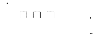
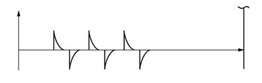
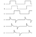
指数型パルスは、方形波パルス・ジェネレータからトランス410へ入力される各方形波入力パルスの立ち上がりエッジの間ならびに立ち下がりエッジの間に生成され、互いに逆の符号を有する(方形波入力パルスの立ち上がりエッジに起因する正の指数型パルス、および方形波入力パルスの立ち下がりエッジに起因する負の指数型パルス)。この種の、図4に示されるようなパルス・ジェネレータ400を使用することによって、隣り合うパルスが逆の極性を有する分離されたパルスのバースト(たとえば、秒当たり500から1500)を皮膚へ印加することが可能になり、それが、皮膚へ単一パルスを単に提供するだけ、あるいは同一極性の多くのパルスを提供するだけの場合に比べてより良好な毛孔拡張効果を提供する。
Exponential pulses are generated during the rising edge and falling edge of each square wave input pulse input from the square wave pulse generator to the transformer 410 and have opposite signs (the rising edge of the square wave input pulse). Positive exponential pulse due to edge and negative exponential pulse due to falling edge of square wave input pulse). By using a
また、パルスのバーストのそれぞれが同一バースト内に逆極性の隣接パルス(たとえば、+‐+‐+‐+‐+‐・・・)を含むパルスのバーストを皮膚に対して出力することによって、皮膚内における可能性のあるあらゆる電流蓄積が、逆極性の隣接パルスを使用することによって生じる相殺効果に起因して未然に防止される。これは、同一極性の電気パルスを出力する従来デバイスと対照的であり、それにおいては患者の皮膚内に電流の蓄積をもたらすことがあり、その電流の蓄積の結果として皮膚に生じる有害な効果を導くことがあり得る。 Also, by outputting a burst of pulses to the skin, each burst of pulses containing adjacent pulses of opposite polarity (eg, +-++-++-++ -...) within the same burst, Any potential current buildup within is obviated due to the canceling effect caused by the use of adjacent pulses of opposite polarity. This is in contrast to conventional devices that output electrical pulses of the same polarity, which can lead to the accumulation of current in the patient's skin, which can have a detrimental effect on the skin as a result of the accumulation of current. Can lead.
前述したとおり、バースト・パルス・ジェネレータは、患者の皮膚へ印加されることになる電流のコントロールが可能となるように、キャパシタに代えて誘導性エレメント(たとえばトランス)を使用する。電気パルス・ジェネレータ用にキャパシタを使用する従来デバイスにおいては、キャパシタが患者の皮膚と結合されるとき、結果としてもたらされる回路が、第1のキャパシタ(パルス・ジェネレータのキャパシタ)およびそれに並列の第2のキャパシタ(負荷として作用する皮膚の容量性/抵抗性効果に起因するキャパシタ)と実質上等しい。電圧が電気パルスとして皮膚へ印加されるとき、第1のキャパシタから第2のキャパシタへの電圧の放電が、最初の短時間にわたって非常に大きな電流スパイクをもたらすが、この大きな電流スパイクは、容易にコントロールすることができない。この結果、大きな電流スパイクによって引き起こされるマイナスの効果が患者の皮膚にもたらされることがあり得る。図4に示されるように、容量性エレメントに代えて誘導性エレメント(たとえばトランス)をパルス・ジェネレータ内に使用することによって、電気パルスを提供する電極を伴うプローブを患者の皮膚と結合したときに電流スパイクがもたらされることはない(『容量性の皮膚』が『誘導性パルス・ジェネレータ』から電流ならびに電圧を滑らかに受け取ることから)。 As previously mentioned, burst pulse generators use inductive elements (eg, transformers) instead of capacitors to allow control of the current that will be applied to the patient's skin. In conventional devices that use a capacitor for an electrical pulse generator, when the capacitor is coupled to the patient's skin, the resulting circuit comprises a first capacitor (pulse generator capacitor) and a second in parallel thereto. Capacitor (capacitor due to the capacitive / resistive effect of the skin acting as a load). When the voltage is applied to the skin as an electrical pulse, the discharge of the voltage from the first capacitor to the second capacitor results in a very large current spike over the first short time, which is easily I can't control it. This can have a negative effect on the patient's skin caused by large current spikes. As shown in FIG. 4, when an inductive element (eg, a transformer) is used in a pulse generator instead of a capacitive element, when a probe with an electrode providing an electrical pulse is coupled to the patient's skin. No current spikes are introduced (since the “capacitive skin” receives current and voltage smoothly from the “inductive pulse generator”).
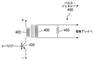
スイッチング・トランジスタ430は、図4Aに示されているような方形波パルスを、図4に示されているとおり、トランス410の一次巻き線へ提供する。図4のパルス・ジェネレータ400によって生成されるパルスは、負荷が純粋な抵抗(または誘導性もしくはそのほかのタイプのリアクタンス性負荷)の場合には、図4Bに示されているような逆対称極性の指数型減衰パルス列となる。パルス・ジェネレータ400を含むこの種の回路は、皮膚のインピーダンスとの優れた結合を提供する。さらに、前述の電流コントロールに加えて、トランス410のインダクタンスは、皮膚のキャパシタンスとともに共振回路を構成し、皮膚の孔または膜組織の開放を達成するためにはこれが望ましい。
電圧波形は、皮膚へ印加されたとき、皮膚の電気的等価回路が抵抗およびキャパシタンスの並列に等しいという事実に起因して好都合に修正される。結果として得られる電圧波形は、より長い立ち上がり時間(RC時定数に起因する)を有し、皮膚のキャパシタンスに依存するが、同一のピーク電流ならびに同一の指数型減衰波形を維持する。 The voltage waveform is conveniently modified due to the fact that when applied to the skin, the electrical equivalent circuit of the skin is equal to the resistance and capacitance in parallel. The resulting voltage waveform has a longer rise time (due to the RC time constant) and maintains the same peak current as well as the same exponential decay waveform, depending on the skin capacitance.
第1の実施態様に従ったこの種の回路は、あらかじめ定義済みの値ならびに電圧もしくは電流の形状のパルスを引き渡す伝統的なパルス・ジェネレータと比較して利点を提供する。第1の実施態様に従った方法によれば、より高いパルス当たりのエネルギ値を引き渡すことが可能であり、また同時に、高電流量が皮膚へ印加されたときに生じる皮膚に対する可能ダメージを回避することが可能である。第1の実施態様内に使用されている回路は、電流、電圧、および波形形状の値を自己調整する。特に、皮膚のインピーダンスが、その皮膚へ最初のパルスが印加された後に減少する。このように、最初のパルスが皮膚へ印加される時点における皮膚のインピーダンスがより高いことから、最初のパルスの電圧は、続くパルスより高くなる。2番目およびその後に続く皮膚へ印加されるパルスの電圧は、皮膚のインピーダンスの減少とともに減少するが、ピーク電流は、同一もしくはほぼ同一の値に維持される。 This type of circuit according to the first embodiment offers advantages compared to traditional pulse generators that deliver pulses in the form of predefined values and voltage or current. According to the method according to the first embodiment, it is possible to deliver higher energy values per pulse and at the same time avoid possible damage to the skin that occurs when a high amount of current is applied to the skin. It is possible. The circuit used in the first embodiment self adjusts the current, voltage and waveform shape values. In particular, the impedance of the skin decreases after the first pulse is applied to the skin. In this way, the voltage of the first pulse is higher than the following pulse because the impedance of the skin at the time the first pulse is applied to the skin is higher. The voltage of the second and subsequent pulses applied to the skin decreases with decreasing skin impedance, but the peak current is maintained at the same or nearly the same value.
代表的な電流ならびに電圧の値を次に示す。ケース1:10キロオームの負荷インピーダンス、100Vのピーク電圧、10ミリアンペアのピーク電流、220マイクロ秒のパルス幅。ケース2:1キロオームの負荷インピーダンス、10Vのピーク電圧、10ミリアンペアのピーク電流、220マイクロ秒のパルス幅。これらのパルスが、好ましくはバースト内において引き渡されるが、その場合のバースト・レートは、機械的振動レートと同一もしくはほぼ同一とする。バースト・レート(および機械的振動レート)の代表的な値は、40Hzから100Hzまでの間となる。 Typical current and voltage values are shown below. Case 1: 10 kOhm load impedance, 100 V peak voltage, 10 mA peak current, 220 microsecond pulse width. Case 2: 1 kOhm load impedance, 10 V peak voltage, 10 mA peak current, 220 microsecond pulse width. These pulses are preferably delivered within a burst, where the burst rate is the same or nearly the same as the mechanical vibration rate. Typical values for burst rate (and mechanical vibration rate) are between 40 Hz and 100 Hz.
本件出願の発明者は、電気パルスが皮膚へ印加されるときと同時に、かつパルスのバースト・レートと同一もしくはほぼ同一の周波数において機械的振動を使用することが、患者の皮膚へ印加される電気パルスの強度(電流ならびに電圧)に対してより大きな耐性を患者に持たせる結果となることも認識した。たとえば、50Hzの電気パルス・バースト・レート(すなわち、パルスのバーストとバーストの間のレート)を使用し、40から60Hzまでの間の範囲で機械的振動を、皮膚への電気パルス・バーストの印加と同時に提供して『マスキング効果』を提供することができる。また発明者は、電気パルス・バースト・レートの基本周波数もしくはその近傍(たとえば、その+/‐10%)において、電気パルス・バースト・レートの第1調波もしくはその近傍において、電気パルス・バースト・レートの第2調波もしくはその近傍において、かつ/または電気パルス・バースト・レートの第3調波もしくはその近傍において機械的振動を使用することが、患者に『快い感覚』を与え、その結果、患者が同時にその患者の皮膚へ印加される、より高い強度の電気パルスに耐えられるようになることも発見した。したがって、50Hzの電気パルス・バースト・レートについて言えば、40から60Hzまで、90から110Hzまで、140から160Hzまで、かつ/または190から210Hzまでのいずれかの機械的振動レートを伴う機械的振動を患者の皮膚に対して同時に印加すればよい。患者の皮膚に対する電気パルス・バーストの印加と同時にその患者の皮膚へ機械的振動を印加することによって、電気パルスのぴりぴりする感覚によって生じる患者の不快レベルが減少する(たとえば、いくぶんマスクされる)。 The inventor of this application uses the electrical vibration applied to the patient's skin at the same time as the electrical pulse is applied to the skin and at the same frequency as the pulse burst rate. It was also recognized that this resulted in patients having greater tolerance for pulse intensity (current and voltage). For example, using an electrical pulse burst rate of 50 Hz (ie, the rate between bursts of pulses), applying mechanical vibrations in the range between 40 and 60 Hz, applying electrical pulse bursts to the skin It can be provided at the same time to provide a “masking effect”. In addition, the inventor can use the electrical pulse burst rate at or near the fundamental frequency of the electrical pulse burst rate (for example, +/− 10% thereof) at the first harmonic of the electrical pulse burst rate or in the vicinity thereof. Using mechanical vibrations at or near the second harmonic of the rate and / or at or near the third harmonic of the electrical pulse burst rate gives the patient a “pleasant sensation” and, as a result, It has also been found that the patient becomes able to withstand the higher intensity electrical pulses that are simultaneously applied to the patient's skin. Thus, for an electrical pulse burst rate of 50 Hz, mechanical vibrations with any mechanical vibration rate from 40 to 60 Hz, 90 to 110 Hz, 140 to 160 Hz, and / or 190 to 210 Hz are What is necessary is just to apply simultaneously with respect to a patient's skin. By applying mechanical vibrations to the patient's skin simultaneously with the application of an electrical pulse burst to the patient's skin, the patient's discomfort level caused by the tingling sensation of the electrical pulse is reduced (eg, somewhat masked).
通常、方形波が皮膚へ印加される場合に、皮膚の容量性効果に起因して、時定数が約3マイクロ秒の指数型減衰電流を獲得することが可能になる。これは、抵抗とキャパシタの並列に対応する回路へ方形波電圧が印加されるときに生じるものである。 Normally, when a square wave is applied to the skin, it becomes possible to obtain an exponential decay current with a time constant of about 3 microseconds due to the capacitive effect of the skin. This occurs when a square wave voltage is applied to a circuit corresponding to a resistor and a capacitor in parallel.
この種の回路を用いれば、トランス410の磁気エネルギに等しい電気エネルギを印加することによって、ピーク電流だけが高められ、最大許容電圧まで皮膚を充電する。この効果は、各パルスが皮膚へ印加されている期間だけにわたる細胞膜もしくは皮膚の孔の開放をもっとも提供しやすい(毛孔拡張効果を達成しやすい)。 With this type of circuit, by applying electrical energy equal to the magnetic energy of the transformer 410, only the peak current is increased and the skin is charged to the maximum allowable voltage. This effect is most likely to provide for the opening of cell membranes or skin pores only during the period in which each pulse is applied to the skin (achieving a pore dilation effect).
皮膚へプローブをあてがう効果は、電極のアレイによって印加される電気パルスに起因して皮膚が振動することである。電気パルスは、好ましくは200から10,000Hzまでの間の固定周波数(最適には、2,500から3,000Hzまでの間の周波数)において印加され、パルスのバーストにグループ化される(たとえば、各バーストが100から1000個の個別のパルスに対応し、そのそれぞれは、同一のパルスのバースト内において隣接パルスに関して逆極性を有する)。各バーストのオン時間は、5から50ミリ秒までの間の固定値となり、2つの連続的なバーストの間のオフ時間は、5から50ミリ秒までの間の固定値となる(好ましいバースト・オン時間は10ミリ秒であり、連続するバーストとバーストの間の好ましいバースト・オフ時間は10ミリ秒である)。 The effect of applying the probe to the skin is that the skin vibrates due to electrical pulses applied by the array of electrodes. Electrical pulses are preferably applied at a fixed frequency between 200 and 10,000 Hz (optimally between 2,500 and 3,000 Hz) and grouped into bursts of pulses (eg, Each burst corresponds to 100 to 1000 individual pulses, each of which has a reverse polarity with respect to adjacent pulses within the same burst of pulses). The on-time of each burst is a fixed value between 5 and 50 milliseconds, and the off-time between two consecutive bursts is a fixed value between 5 and 50 milliseconds (the preferred burst The on-time is 10 milliseconds, and the preferred burst off time between successive bursts is 10 milliseconds).
前述したとおり、電極を介して皮膚へ印加される電気パルスは、好ましくはピーク‐ピーク電圧が160V、周波数が2,500から3,000Hzまでの間のいずれかに固定される指数型パルスとする。この種の電気パルスを提供する1つの方法は、図4に示されているようなパルス・ジェネレータ400に対応する電気的構造を用いることであり、それにおいてはパルス・ジェネレータ400のエレメントとしてトランス410が使用される。
As described above, the electric pulse applied to the skin through the electrodes is preferably an exponential pulse with a peak-to-peak voltage of 160 V and a frequency fixed between 2,500 and 3,000 Hz. . One way to provide this type of electrical pulse is to use an electrical structure corresponding to the
トランス410をはじめ、パルス・ジェネレータ400のそのほかのエレメントは、好ましくは図5に示したプローブ500内に収容されている。
The transformer 410 and other elements of the
図4に戻るが、トランス410の一次巻き線420は、オン・オフを切り替えるトランジスタ430によって駆動され、トランス410の二次巻き線440は、電極のアレイ(図1Aまたは1B参照)と直接結合され、それらの間には電気抵抗450が備えられる。電気抵抗450は、200キロオームもしくはそれを含む所定の範囲内(たとえば、100キロオームから500キロオームまで)の値であり、電極のアレイが皮膚へあてがわれてなく、それが結果として開放回路として動作されることになる場合の高電圧を回避するために備えられる。その種の状況においては、ピーク‐ピーク電圧が400Vもしくはその近辺の値となる。
Returning to FIG. 4, the primary winding 420 of the transformer 410 is driven by a
皮膚へ印加される電気パルスとともに、第1の実施態様においては、皮膚上へ塗布される物質の吸収を増加させるために、機械的振動もまた皮膚に与えられる。 Along with the electrical pulses applied to the skin, in a first embodiment, mechanical vibrations are also applied to the skin to increase the absorption of the substance applied onto the skin.
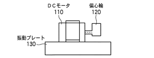
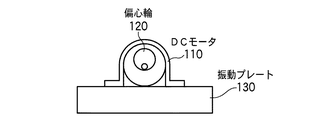
吸収効果は、同時的な毛孔拡張の増加によって高められるが、それにおいては、位相ならびに周波数において機械的振動が電気パルスの印加と同期されるときに吸収効果が最大となる。したがって、前述した例では、電極のアレイを介して皮膚に、たとえば50Hzとするバースト・オン/オフ周波数において電気パルス(2,200Hz)のバーストが与えられている間にわたり、振動プレートによって皮膚がまた、同じ周波数、たとえば50Hzで機械的に振動される。この機械的振動および電気パルスの印加は、皮膚の吸収効果を増加させるために、好ましくは互いに関して同相で提供される。この周波数ならびに位相の同期を達成する方法としては、いくつかのよく知られた方法がある。ここで述べている好ましい実施態様においては、機械的振動の提供に使用されるモータ(たとえば、図1Aおよび1Bを参照されたい)の偏心輪の運動を光学センサ(図示せず)によって検出し、検出した運動に基づいて電気パルスのバーストをゲートしている。 The absorption effect is enhanced by a simultaneous increase in pore expansion, where the absorption effect is maximized when mechanical vibrations are synchronized with the application of electrical pulses in phase as well as frequency. Thus, in the example described above, the skin is also caused by the vibrating plate while the skin is being given a burst of electrical pulses (2,200 Hz) at a burst on / off frequency of 50 Hz, for example, through the array of electrodes. Are mechanically vibrated at the same frequency, eg 50 Hz. This application of mechanical vibrations and electrical pulses is preferably provided in phase with respect to each other to increase the absorption effect of the skin. There are several well-known methods for achieving this frequency and phase synchronization. In the preferred embodiment described herein, the motion of the eccentric wheel of a motor (eg, see FIGS. 1A and 1B) used to provide mechanical vibration is detected by an optical sensor (not shown); A burst of electrical pulses is gated based on the detected motion.
このように前述した例においては、電気パルスのバーストが電極のアレイを介して皮膚に与えられている間にわたり、振動プレートを介して皮膚が同じ周波数で機械的に振動される。この機械的振動ならびに電気パルスの印加は、皮膚の吸収効果を増加させるために、好ましくは互いに関して同相で提供される。 Thus, in the example described above, the skin is mechanically vibrated at the same frequency through the vibrating plate while a burst of electrical pulses is applied to the skin through the array of electrodes. This mechanical vibration as well as the application of electrical pulses are preferably provided in phase with respect to each other in order to increase the absorption effect of the skin.
それに加えて、皮膚の表面と直交して機械的振動が印加されるとき、吸収効果がさらに増加される。出願人は、いずれかの特定の動作理論に限定されることを意図していないが、本発明の1ないしは複数の実施態様における物理現象の1つの可能性のある説明は、電気パルスが皮膚を『引き伸ばし』、その結果、皮膚の孔の直径が周期的に増加する間に、同時に機械的振動が皮膚の内側へ(開いた孔を介して)物質(ジェル、液体、またはクリーム)を『送り込む』というものである。機械的刺激と電気的刺激の同期は、(皮膚に対する電気的刺激に起因して)孔が最大『開放』直径にある同じ瞬間に、(皮膚に対する機械的刺激に起因して)『送り込み』作用が生じる効果を達成する。 In addition, the absorption effect is further increased when mechanical vibration is applied perpendicular to the skin surface. Although Applicants are not intending to be limited to any particular theory of operation, one possible explanation for a physical phenomenon in one or more embodiments of the present invention is that an electrical pulse is applied to the skin. “Stretching”, as a result, mechanical vibrations “feed” substances (gels, liquids, or creams) into the inside of the skin (via open pores) while the pore diameter of the skin increases periodically ]. The synchronization of mechanical and electrical stimulation is due to the “feed” action (due to mechanical stimulation to the skin) at the same moment when the hole is at the maximum “open” diameter (due to electrical stimulation to the skin). To achieve the effect.
本発明の第1の実施態様に従った装置は、次に示す2つの主要部分を有するプローブを含む:
(A)電源(たとえばバッテリ)ならびにパルス・ジェネレータを含むハンドル;および、
(B)振動を発生するためのコンポーネントを含み、かつ電極のアレイを含む振動ヘッド。
The apparatus according to the first embodiment of the invention comprises a probe having two main parts:
(A) a handle including a power source (eg, a battery) and a pulse generator; and
(B) A vibrating head that includes components for generating vibration and includes an array of electrodes.
第1の実施態様の好ましい構成においては、振動ヘッドが、皮膚に対する振動を発生するためのDC電気モータを含んでいる。図1Aおよび1Bは、DC電気モータ110を2つの異なる方向から示しており、DC電気モータ110の回転シャフトが、偏心運動を提供する偏心輪120になっている。この偏心運動は、DC電気モータ110の回転の間に振動プレート130(DC電気モータ110と直接結合されている)上に、DC電気モータ110の回転と同じ周波数(たとえば、50Hzもしくは60Hzまたはそのほかの望ましい周波数)の振動を発生する。このほかの電気パルスの提供に同期した振動を生じさせる方法も企図されるが、結局は本発明の範囲内に帰する。注意すべきは、前述したとおり、電気パルスのバースト・レートと同一もしくは略同一であるが、互いの同期を必須としない機械的パルスの使用が、皮膚に対する電気パルスだけを受けることによってもたらされるブーンという音を伴ったぴりぴりした感覚に関連付けされる患者の不快レベルを下げるという点において良好な効果を提供することである。また、各バースト内において互いに逆極性の隣接パルスを使用することは、患者の皮膚に対する電流の蓄積をまったくもたらさないが、同一極性の電気パルスを使用し、それが患者の皮膚へ与えられることになる従来デバイスにおいては、それがその有害な効果となり得る。
In a preferred configuration of the first embodiment, the vibration head includes a DC electric motor for generating vibrations against the skin. 1A and 1B show the DC
すでに説明したが、図4は、図2Aおよび2Bに示されている電極のアレイに対して電気パルスを提供するための回路を示している。図4の回路は、パルス・ジェネレータ400に対応しており、好ましくは図5のプローブ500のハウジング内に配置される。パルス・ジェネレータ400によって生成された電気パルスは、それらのパルスが皮膚へ与えられるとき、好ましくはピーク‐ピーク電圧が160V、周波数が2,500Hzから3,000Hzの間となる指数型パルスとなる。当然ではあるが、このほかのピーク‐ピーク電圧(たとえば、100V〜200V)ならびに動作周波数(50Hz〜15,000Hz)を採用してもよいが、結局はここで述べているとおり本発明の範囲内に帰する。それに代えて、鋸歯状波または正弦波パルスが電極へ提供されるようにしてもよいが、指数型パルスが、より良好な皮膚の毛孔拡張結果を提供すると見られる。
As already explained, FIG. 4 shows a circuit for providing electrical pulses to the array of electrodes shown in FIGS. 2A and 2B. The circuit of FIG. 4 corresponds to
図1Aおよび1Bには、DC電気モータ110と物理的に結合される振動プレート130が示されている。振動プレート130は、好ましくは50×50mmのサイズ(このほかのサイズも可能であるが結局は本発明の範囲内に帰する)であり、図2Aに示されているとおり、その上には電極のアレイを形成するための平行金属帯が配置されている。振動プレート130は、皮膚の吸収効果を高めるために、電極のアレイ(振動プレート上に配置される)を介して皮膚に対して提供される電気パルスと同一の位相ならびに周波数において振動される。
FIGS. 1A and 1B show a vibrating
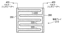
図2Aは、振動プレート130の皮膚側表面上に備えられる電極アレイ210の第1の実施態様を示しているが、これに示されているとおり、それぞれを好ましくは50mm×4mmのサイズとする5本の平行金属帯220が備えられている。5本の電極220のそれぞれの間には、隣接配置される電極から好ましくは6mmの間隔が設けられる。電極220は、交互に電気的に接続される(たとえば、第1行、第3行、および第5行が、電気ライン250によって互いに電気的に接続されており、第2行および第4行が、電気ライン260によって互いに電気的に接続されている)。7もしくは8の電極を有するというように、2を超える数の電極を有するこのほかの電極アレイの構成も可能であるが、結局は本発明の範囲内に帰することになる。
FIG. 2A shows a first embodiment of the
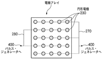
図2Bは、振動プレートの皮膚側表面上に備えられる電極アレイの第2の実施態様を示している。図2Bにおいては、それぞれが4mmの直径を有する25個の円形電極230があり、それぞれは、隣接配置される円形電極から少なくとも6mmの間隔が設けられる。これらの円形電極230は、交互に互いに電気的に接続される(たとえば、第1行、第3行、および第5行の電極が、電気ライン270によって互いに電気的に接続されており、第2行および第4行の電極が、電気ライン280によって互いに電気的に接続されている)。図2Bに示されている円形電極230の間の間隔は1から20mmまでの間において多様なものとなり、また円形電極230のサイズは直径が1から20mmまでの間において多様なものとなり得る。
FIG. 2B shows a second embodiment of the electrode array provided on the skin side surface of the vibrating plate. In FIG. 2B, there are 25 circular electrodes 230 each having a diameter of 4 mm, each spaced at least 6 mm from the adjacent circular electrodes. The circular electrodes 230 are alternately electrically connected to each other (eg, the electrodes of the first row, the third row, and the fifth row are electrically connected to each other by an
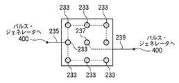
図2Cは、本発明の第3の実施態様に従って、振動プレートの、皮膚に面する外側表面上に備えられた電極のアレイを示している。図2Cにおいては、振動プレートの周縁に配置された電極233が示されており、それらは互いに電気的に結合され、さらに第1の電気接続235を介してパルス・ジェネレータ400の第1の出力へ結合される。また図2Cには、中心に配置された電極237も示されており、これはほかのいずれの電極とも電気的に結合されることなく、第2の電気接続239を介してパルス・ジェネレータ400の第2の出力へ電気的に結合される。
FIG. 2C shows an array of electrodes provided on the skin-facing outer surface of the vibrating plate, according to a third embodiment of the present invention. In FIG. 2C,
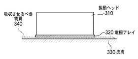
図3は、本発明の一実施態様に従って使用され、前もって皮膚へ塗布された物質をより良好に吸収させるために皮膚に対して電気的および機械的刺激の両方を提供するプローブの振動ヘッド310の側面図である。図3に示されているとおり、振動ヘッド310は、皮膚側のその表面上に備えられる電極アレイ320を含む。電極アレイ320は、たとえば図2Aまたは2Bのいずれかに示されているような態様で備えることができる。電極アレイ320と皮膚330の間には、吸収させるべき物質340が提供されており、それにおいて物質340は、前もって皮膚330に塗布されている(たとえば、プローブが皮膚330へあてがわれる前の30秒から2分までの間に皮膚に塗布される)。機械的振動および電気パルスの印加は、皮膚330への物質340の吸収を高める。
FIG. 3 illustrates a
図5は、本発明の1ないしは複数の実施態様に従って電気的および機械的刺激をともに皮膚へ与えるために使用することのできるハンド‐ヘルド・プローブ500の1つの構成を示している。プローブ500は、ユーザが片手で容易に持つことができるように構成されている。ユーザが手で握ってプローブ500を保持するプローブ500のボトム部分には、電気ケーブルを電気アウトレット(たとえば壁のアウトレット)へ結合し、AC電圧をプローブ500へ供給するためのアウトレット510を含めることができる。それに代えて、プローブ500のハウジング内に配置されるバッテリ(図示せず)を介してバッテリ電源を使用することもできる。バッテリ電源は、AC電源が容易に利用できない場合に使用することができる。また図4のパルス・ジェネレータ400は、好ましくはプローブ500のハンドル部分に収容される。
FIG. 5 illustrates one configuration of a hand-held probe 500 that can be used to provide both electrical and mechanical stimulation to the skin in accordance with one or more embodiments of the present invention. The probe 500 is configured so that the user can easily hold it with one hand. The bottom portion of the probe 500 that is held by the user to hold the probe 500 includes an
プローブ500のヘッド部分は、振動プレート130(図1Aまたは1B参照)が備えられる部分であり、また振動プレート130へ機械的振動を提供するDC電気モータ110(同様に図1Aまたは1B参照)が好ましくは収容されている部分でもある。電極のアレイ(図2Aまたは2B参照)は、振動プレート130の外側表面に備えられ、その結果、プローブ500によって治療されるべきユーザの皮膚に面する。
The head portion of the probe 500 is a portion provided with a vibration plate 130 (see FIG. 1A or 1B), and a DC electric motor 110 (also see FIG. 1A or 1B) that provides mechanical vibration to the
プローブを皮膚へあてがう一般的な時間は、数十秒台から数分台までとすることができる。 Typical time for applying the probe to the skin can be in the tens of seconds to minutes.
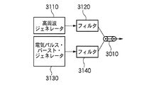
第4の実施態様においては、図6に示されているとおり、パルス・ジェネレータ400の出力(図4参照)がDC電流ジェネレータ610へ接続され、それが、前述した皮膚吸収/毛孔拡張効果に加えてイオン導入効果を誘発する。イオン導入効果については、当業者に周知であり、DCもしくはパルス化DCのいずれのイオン導入電気ジェネレータも現在市販されているものがいくつかある。DC電流ジェネレータ610によるDC出力は、プローブの電極と、患者の身体に接続されたグラウンド・プレートの間に印加される。患者の皮膚へ吸収させるべき物質に依存して、患者グラウンド・プレートコネクションが、当業者に周知の方法でDC電流ジェネレータ610の正または負のいずれかと結合される。連続DC電流の使用に代えて、連続DC電流の場合に等しい平均電流値を有する、5から50%までの間のデューティ・サイクルを有し、10から5000Hzまでの間の周波数を有するDC電流パルスを提供することも可能である。その種の場合においては、DC電流パルスのピーク電流が、パルス(オン)されている時間にわたってより高くなる。 In a fourth embodiment, as shown in FIG. 6, the output of the pulse generator 400 (see FIG. 4) is connected to a DC current generator 610, which in addition to the skin absorption / pore expansion effect described above. To induce an iontophoretic effect. The iontophoretic effect is well known to those skilled in the art, and there are a number of commercially available iontophoretic generators, either DC or pulsed DC. The DC output by the DC current generator 610 is applied between the electrode of the probe and a ground plate connected to the patient's body. Depending on the material to be absorbed into the patient's skin, the patient ground plate connection is coupled to either the positive or negative of the DC current generator 610 in a manner well known to those skilled in the art. Instead of using a continuous DC current, a DC current pulse having a duty cycle between 5 and 50% and a frequency between 10 and 5000 Hz with an average current value equal to that for continuous DC current Can also be provided. In such cases, the peak current of the DC current pulse is higher over the time it is pulsed (on).
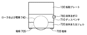
第5の実施態様においては、図7および8に示されているとおり、クリームまたはジェル720を保持するべく構成されたディスペンサまたはチャンバ710が、プローブの振動ヘッド内に組み込まれる。ディスペンサまたはチャンバ710は、電極アレイ705と振動プレート130の間に備えられる。電気パルスのバーストは、液体を施与する導体ローラ740および電極アレイ705によって印加される。第3の実施態様における場合のように、電極アレイ705と患者身体の間にDC電流を追加して、さらにイオン導入効果を誘発することもできる。振動ヘッドが患者の皮膚上において移動されるとき、ローラ740が、液体もしくはクリームまたはジェル720を患者の皮膚へ施与する。
In a fifth embodiment, as shown in FIGS. 7 and 8, a dispenser or chamber 710 configured to hold a cream or gel 720 is incorporated into the vibrating head of the probe. A dispenser or chamber 710 is provided between the electrode array 705 and the
振動ヘッド内のローラ740が配置されるチャンバ710には、液体、クリームまたはジェル物質720が、取り外し可能なキャップ(図示せず)を介して充填される。より詳細には、ユーザがこのキャップを取り外し(たとえば、キャップを開ける方向に回してプローブのヘッドから外し)、液体注ぎ口760を介して、患者の皮膚へ与えられることになる物質720をチャンバ710内へ充填する。その後ユーザは、キャップを閉じ(たとえば、キャップを閉じる方向に回して再び液体注ぎ口760に締め付け)、それによって、物質720がローラ740によって患者の皮膚へ塗布される準備が整うまで、プローブのチャンバ710内にそれを保持する。 The chamber 710 in which the roller 740 in the vibrating head is placed is filled with a liquid, cream or gel substance 720 via a removable cap (not shown). More specifically, the user removes the cap (eg, turns it in the direction of opening the cap and removes it from the probe head), and chamber 710 contains a substance 720 to be delivered to the patient's skin via the liquid spout 760. Fill in. The user then closes the cap (e.g., turns the cap in the closing direction and tightens again to the liquid spout 760), thereby allowing the probe chamber to remain ready for application of the substance 720 to the patient's skin by the roller 740. Hold it in 710.
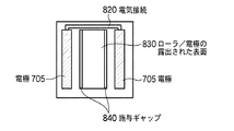
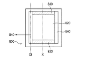
図8は、電極705の正面図を示しており、それにおいては電極が電気接続820によって互いに電気的に接続された2本の電極の帯として示されている。当然ではあるが、それに代えて、図2Aならびに2Bに示されているような、このほかのタイプの電極アレイも、この第5の実施態様において使用することができる。図8を参照すると、ローラ740の、患者の皮膚へ物質を塗布する露出された表面830が示されている。施与ギャップ840もまた図8に示されており、これらの施与ギャップ840は、チャンバ710内の液体、クリームまたはジェル物質720が徐々にチャンバ710から出ることを可能にし、その結果、ローラ740によって患者の皮膚へ塗布されることが可能になる。
FIG. 8 shows a front view of electrode 705, where the electrodes are shown as two strips of electrodes that are electrically connected to each other by
本発明の第6の実施態様においては、皮膚の吸収を高めるための装置が、電極のアレイ、および電極のアレイと電気的に結合されるパルス・ジェネレータを含む。電極のアレイの配置には、たとえば図2A〜2Cに示されている配置のいずれを用いてもよい。第6の実施態様の好ましい具体化においては、パルス・ジェネレータ400から電極のアレイに向けて出力された電気パルスが、図4Bに示されているパルス列等のような指数型パルス列になる。指数型電気パルスは、電極のアレイを介して皮膚へ印加され、図4、4A、4Bに示されているとおり、方形波電圧によって駆動される一次巻き線を伴う高電圧トランスの二次巻き線により生成される。
In a sixth embodiment of the invention, an apparatus for enhancing skin absorption includes an array of electrodes and a pulse generator electrically coupled to the array of electrodes. For example, any of the arrangements shown in FIGS. 2A to 2C may be used for the arrangement of the electrode array. In a preferred embodiment of the sixth embodiment, the electrical pulses output from the
この第6の実施態様においては、これまでの実施態様とは異なり、振動ヘッドが使用されず、電極のアレイを介した皮膚への電気パルスの提供によってのみ、皮膚吸収の増加が得られる。第6の実施態様に従った電極のアレイは、プローブのヘッドにあるプレート上に備えられ、それにおいてはヘッドならびにプレートが振動しない。このように第6の実施態様においては、図1Aならびに1Bに示されているような構造が使用されないが、プレートだけは、プローブのヘッドの適正な位置に電極を保持するために必要となる。 In this sixth embodiment, unlike the previous embodiments, no vibration head is used and an increase in skin absorption is obtained only by providing an electrical pulse to the skin through the array of electrodes. The array of electrodes according to the sixth embodiment is provided on a plate in the probe head, in which the head as well as the plate do not vibrate. Thus, in the sixth embodiment, a structure as shown in FIGS. 1A and 1B is not used, but only a plate is required to hold the electrodes in the proper position of the probe head.
第7の実施態様においては、第1〜第5の実施態様の場合と同様に振動ヘッドが使用されるが、プローブに備えられるコントロール(たとえばスイッチ)によって振動ヘッドのオンまたはオフを行うことが可能である。このコントロールを、プローブのオペレータは、患者の治療を行うために容易に操作することができる。 In the seventh embodiment, a vibrating head is used as in the first to fifth embodiments, but the vibrating head can be turned on or off by a control (for example, a switch) provided in the probe. It is. This control can be easily manipulated by the probe operator to treat the patient.
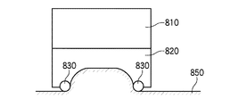
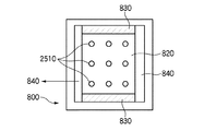
次に、図9〜11を参照して本発明の第8の実施態様を説明する。図9は、プローブのヘッド800の正面図を示しており、それにおいては、プローブの、患者の皮膚へあてがわれる部分が示されている。図10は、1つのベルト軸に沿って切断した断面図であり、図11は、プローブのヘッドの中心に沿って切断した断面図である。
Next, an eighth embodiment of the present invention will be described with reference to FIGS. FIG. 9 shows a front view of the
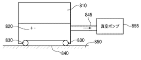
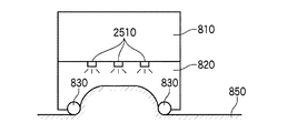
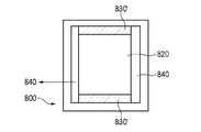
第8の実施態様は、あらかじめ皮膚へ塗布される物質、たとえば前もって皮膚へ塗布されたコラーゲン等の物質の極めて均等な皮下吸収を提供する。第8の実施態様において、皮膚へあてがわれるプローブのヘッド800は、振動プレート810、真空チャンバ820、ローラ830、およびローラ830の周囲に配置されるベルト840を含む。ローラ830は、導体ローラであり、それにおいてローラ830は、振動プレート810上に備えられる電極(たとえば、図2A〜2Cを参照されたい)と電気的に結合されている。ほかの実施態様における場合と同様に、パルス・ジェネレータ(たとえば、図4を参照されたい)が、患者の皮膚へ電気パルスを(導体ローラを介して)与えるために、振動プレート810上の電極と電気的に結合されている。
The eighth embodiment provides very even subcutaneous absorption of substances that are pre-applied to the skin, such as collagen that has been pre-applied to the skin. In an eighth embodiment, the
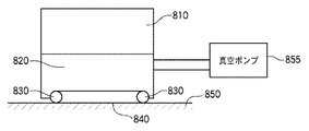
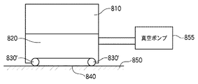
第8の実施態様においては、ローラ830が互いに約40mmだけ離隔されている。当然のことではあるが、このほかの離隔距離も可能であるが、結局は本発明の範囲内に帰する(たとえば、20mm〜80mmの離隔)。ローラ830は、真空チャンバ820の一方の端に配置されており、それにおいて真空チャンバ820は開口を有し、そこにはパイプ845が結合され、さらにそれが真空ポンプ855へ結合されている。
In the eighth embodiment, the
真空ポンプ855が作動されると、真空チャンバ820が皮膚850上に吸引効果をもたらし、それによってローラ830と皮膚850の間のより強い接触が可能になり、さらにそれによって、振動プレート810により生成される振動に加えて、皮膚850に対する追加のマッサージ効果が作り出される。ローラ830の両端にはベルト840が備わり、好ましくはそれをラバー・ベルトとする。ベルト840は、皮膚850と真空チャンバ820の本体の間における直接摩擦を回避するために使用されている。
When the
この第8の実施態様は、良好な皮膚吸収結果を提供し、セルライトを減少させるための物質を皮膚へ塗布した後の皮膚のセルライトを減少させる。この種の皮膚へ塗布できるセルライトを減少させるための物質は、たとえばジャルロン酸(jarulon acid)とすることができる。この種の物質は、皮膚上に前もって塗り広げておき、前述した実施態様の1つを使用して皮膚に吸収させることができる。 This eighth embodiment provides good skin absorption results and reduces skin cellulite after applying a substance to reduce cellulite to the skin. A substance for reducing cellulite that can be applied to this type of skin can be, for example, jarlon acid. This type of material can be pre-applied on the skin and absorbed by the skin using one of the previously described embodiments.
また、第8の実施態様は、第1〜第5の実施態様における場合のように振動プレートを有するとして説明されているが、その代替構成の中では、第6の実施態様ならびに(振動プレートがオフのときの)第7の実施態様における場合のように、非振動プレートを使用することができる。その場合においては、真空チャンバの上側に配置されるプレートが非振動となるが、そこに配置されている電極は含まれる。 The eighth embodiment is described as having a vibration plate as in the first to fifth embodiments, but in the alternative configuration, the sixth embodiment and (the vibration plate is As in the seventh embodiment (when off), non-vibrating plates can be used. In that case, the plate placed on the upper side of the vacuum chamber is non-vibrating, but the electrodes placed there are included.
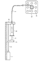
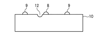
次に、図12〜14を参照して第9の実施態様を詳細に説明する。第9の実施態様は、モータ1、スクリュー2、スライド3、フレーム4、ピストン5、シリンジ6、パイプ(または管)7、およびヘッド10上の中心電極8ならびに周囲電極9(中心電極8の外側に配置されている)を含む。ヘッド10は、プローブのヘッド部分、たとえば、前述の実施態様の図5に示されているプローブのヘッドである(第5の実施態様においては、電極プレートに隣接するヘッド内のチャンバ内に物質が収められ、その場合にはシリンジが不要になることから例外とする)。
Next, the ninth embodiment will be described in detail with reference to FIGS. The ninth embodiment includes a motor 1, a
この第9の実施態様においては、シリンジ6が好ましくは、使い捨てタイプの一回使用シリンジであり、プローブに隣接して配置される(図12には、プローブのヘッド10だけが示されており、プローブの残りの部分は、図12に提供されている図中のヘッド10の背後に隠れている)。シリンジ6は、フレーム4内に挿入もしくは嵌め込まれ、フレーム4との相対的な移動はない。たとえば、このフレーム4は、治療されることになる患者が位置するベッドに隣接するテーブル上に配置することができる。
In this ninth embodiment, the
ピストン5は、フレーム4と相対的に移動可能であり、それにおいてその移動は、モータ1、スクリュー2、およびスライド3によってもたらされ、それらは統一的に移動手段として作用する。図12に示されている構成を用いると、プローブが自立構造となり、フレーム4と相対的に(シリンジ6とプローブのヘッド10を結合する管7を介してシリンジ6との結合を維持しつつ)所定量(たとえば、管7の長さに依存するが、1〜10フィート)の移動を行うことが可能になる。すなわち、シリンジ6を含むフレームをベッドに隣接するテーブル上に配置した状態でプローブを動かして、ベッド上に横たわる患者の皮膚の異なるエリアを治療することができる。代替構成においては、プローブならびにシリンジ6をともに、単一ブロック構成としてフレーム4上にマウントすることができる。その構成においては、全体のフレームを患者の皮膚の異なるエリアへ移動させ、フレーム内に挿入されているプローブを介して患者の治療を行うことができる。プローブのヘッドは、患者の皮膚に対してそれを配置することができるように、フレームの一端から外側へ延びる。
The piston 5 is movable relative to the frame 4, in which its movement is effected by the motor 1,
好ましい具体化においては、モータ1が、プローブへ供給される電源とは異なる電源によって電源供給される。しかしながら、別の具体化においては、モータ1およびプローブが同一の電源によって電源供給される。 In a preferred embodiment, the motor 1 is powered by a power supply that is different from the power supplied to the probe. However, in another embodiment, the motor 1 and the probe are powered by the same power source.
パイプまたは管7は、シリンジ6とプローブのヘッド10を接続するために使用される。管7は、好ましくは使い捨ての一回使用コンポーネントであり、たとえば柔軟なプラスチック製の管とすることができる。ヘッド10は、好ましくは、ほかの実施態様に関して前述したような振動ヘッドとする。代替構成においてはヘッド10が振動せず、その代替構成においては電気パルスだけが皮膚へ提供される(それにより皮膚のエレクトロポーレーション(electroporation)が行われて、シリンジ6および管7を介して皮膚へ提供される物質が吸収される)。管7は、好ましくは直径が0.5〜3ミリメートルであり、液体もしくはクリーム状の物質が管7を通って流れ、シリンジ6と結合される管7の第1の端部とは反対側の第2の端部において管7からそれを排出できるサイズに設定される。皮膚へ塗布されるこの種の物質としては、水性コラーゲン、水性エラスティン、およびそのほかのタイプの薬剤等、多数のものを含めることができる。
A pipe or tube 7 is used to connect the
ここで図14を参照するが、ヘッド10の端部に配置され、かつ中心電極8の周囲を囲むグルーブ11に至るまでの間に提供されているグルーブ12によって、管7とヘッド10が結合される。グルーブ12は、管7を受け入れ、滑り嵌めを提供できるサイズに設定されており、それにおいて管7は、好ましくはグルーブ12の一端が配置されるヘッド10の端部からグルーブ12内へ管7を送り込むことによってグルーブ12内に嵌め込まれる。この第9の実施態様においては、管7がヘッド10の上側表面(電極8、9が配置されている表面)の上に達しないように、あるいは管7がヘッド10の上側表面(プレート)のわずか下側まで達するようにグルーブ12のサイズが設定される。すなわち、治療の間に患者の皮膚に沿ってプローブのヘッド10を移動させるとき、患者が管7を知覚することがない。好ましくは、第9の実施態様に従った方法および/または装置を介して、患者の治療の間にわたり、管7が患者の皮膚と接触することがない。ヘッド10のトップ表面は、好ましくはプレート状の構成であり、患者の皮膚へ滑らかな感覚を提供する。
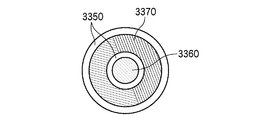
Referring now to FIG. 14, the tube 7 and the
ヘッド10のトップ表面上には、1つの中心電極8、および中心電極8の周囲に配置された複数の周囲電極9が備えられている。中心電極8の周囲を囲むグルーブまたはトラフ11は、好ましくは幅が1mmであり、それにおいてグルーブ11は、管7の一部が配置されるグルーブ12の一つの端部と結合している。すなわち、シリンジ6から(モータ1、スクリュー2、およびスライド3の動作を介して)物質が送出されると、その物質が管7(グルーブ12内に配置されている)を通って流れ、それによってグルーブ11内へ流れ込む。物質は、中心電極8の周囲を囲むグルーブ11内に集まり、第9の実施態様を介したエレクトロポーレーション(electroporation)治療(電気パルスならびに機械的振動を使用する)を施す間に皮膚によって吸収される。ヘッド10のトップ表面(プレート)が患者の皮膚と接触するとき、グルーブ11内の物質が患者の皮膚と接触し、その皮膚によって吸収される。
On the top surface of the
図12には、8個の周囲電極9が示されているが、第9の実施態様に従った本発明は、異なる数の周囲電極9を伴って動作することが可能である。たとえば、異なる構成においては、互いに反対側に(それらの間に中心電極8を伴って)配置された最小限2つの周囲電極9を使用することができる。また、第9の実施態様の別の違った構成においては、4個の周囲電極9を使用すること、あるいは8を超える数の周囲電極9(たとえば、中心電極8の周りを囲む16個の電極、32個の電極、または3、5、もしくは7といった奇数の周囲電極)を使用することもできる。
Although eight
図4(図4Aおよび4Bを併せて参照されたい)に示されているようなパルス・ジェネレータを使用して、プローブのヘッド10上に配置された電極8、9へ電気パルスを供給することができる。すでに説明したとおり、電気パルスの好ましい形状は、図4Bに示されているような指数関数形状である。それに代えて、正弦波もしくは鋸歯状波を供給してもよいが、指数型パルスの方が、より良好な皮膚の毛孔拡張効果を提供する。第9の実施態様に使用できるパルス・ジェネレータの動作については、前述の第1の実施態様に関連して詳細に説明済みであり、簡明のため、ここではそれを繰り返さない。
A pulse generator such as that shown in FIG. 4 (see also FIGS. 4A and 4B) may be used to supply electrical pulses to the
パルス・ジェネレータの2つの出力の一方(図4参照)が中心電極8に接続されており、パルス・ジェネレータの2つの出力の他方が周囲電極9の1つに接続されている。周囲電極9は、ヘッドの裏側において互いに電気的に結合されており(図2Cの破線を参照されたい)、その結果、パルス・ジェネレータの2つの出力の当該他方の上に供給される電気パルスのそれぞれは、周囲電極9のすべてに対して同時に供給される。
One of the two outputs of the pulse generator (see FIG. 4) is connected to the
8つの周囲電極9のそれぞれから皮膚へ提供される電気パルスの電圧は、1つの中心電極8から皮膚へ提供される電気パルスの電圧に対する『グラウンド』と考えることができる。中心電極8が、8つの周囲電極9のそれぞれより多くの電流を運ぶことから、周囲電極9がグラウンド接続のように作用し、それにおいて8つの周囲電極9のそれぞれによって運ばれる電流は、中心電極8によって運ばれる電流の約8分の1となる。
The voltage of the electric pulse provided to the skin from each of the eight surrounding
シリンジ6のピストン5は、モータ1によって駆動され、好ましい具体化においてはそれをDC電気モータとする。モータ1は、スクリュー2に接続されており、それがスクリュー2の特定の位置において、スクリュー2に取り付けられているスライド3を介してピストン5を移動する。プローブのヘッド10が患者の皮膚上に置かれると、電気パルスが電極8、9へ引き渡され、シリンジ6のピストン5が、液体もしくはクリーム状の物質(または薬剤)をシリンジ6内から患者の皮膚へ引き渡すためにモータ1によって移動される。液体、クリーム、または薬剤は、好ましくは患者の皮膚へゆっくりとコントロールされた態様で供給され、それらの物質が適正に皮膚内へ適切に吸収されることを可能にする。たとえば第9の実施態様に従った方法または装置を介して、水性コラーゲン、水性エラスティン、麻酔薬、またはそのほかのタイプの薬剤をシリンジ6内へ供給し、その後(それらを吸収させるべき)患者の皮膚へ供給することができる。
The piston 5 of the
第9の実施態様の、皮膚への電気パルスの印加およびそれと同期した皮膚への機械的振動(ほかの実施態様に関する振動プレートの説明を参照されたい)の同時の印加による皮膚吸収の向上は、シリンジ6によって引き渡される薬剤もしくはそのほかのタイプの物質の吸収を可能にする。代表的な薬剤の吸収量は、1〜5分当たり1立方センチメートルであり、第9の実施態様に従った方法および装置を使用する。これに関して言えば、ピストン5の移動が、患者の治療の間にわたってシリンジ6から適正な量の物質が排出されるようにタイミング設定され、それにおいては、プローブをオンにしたとき、そのイベントが、動作を開始するためのトリガ信号をモータ1へ提供することになる。続いてモータ1の動作がシリンジ6内の物質をシリンジ6から中心電極8の周囲を囲むグルーブ12内へ押し出す。
The enhancement of skin absorption of the ninth embodiment by the simultaneous application of electrical pulses to the skin and synchronized mechanical vibrations to the skin (see description of the vibration plate for other embodiments) is: Allows absorption of drugs or other types of substances delivered by the
物質は、前もってシリンジ内に取り入れられており、その結果、中に物質が供給済みのシリンジ6をフレーム4へ取り付け、管7を結合することによって、ヘッド10、すなわちそのプレートの外側表面上に電極8、9を伴うヘッド10を有するプローブを用いて薬剤および/またはそのほかの物質を患者の皮膚へ導くことのできる装置が提供される。すでに説明したとおり、ヘッド10が振動し、その結果、電気的振動ならびに機械的振動の両方が患者の皮膚へ提供され、同時に薬剤またはそのほかの物質が患者の皮膚へ(患者の治療の間に患者の皮膚と接触するトラフまたはグルーブ12内に配分された物質として)提供される。機械的振動および電気パルスの両方を使用するほど良好ではないが、皮膚の毛孔拡張効果を提供する代替構成においては、電気パルスだけが患者の皮膚へ提供される(ヘッドが振動しない)。この構成は、より安価に作られ、場合によっては適切なこともある。
The substance has been previously taken up in the syringe, so that the
モータ1、スクリュー2、スライド3、ピストン5、シリンジ6、フレーム4、および管7には、異なるタイプのプローブを結合し、皮膚吸収を高めるため、および経皮薬剤投与のための装置を提供することができる。たとえば、このほかの実施態様(プローブのヘッド内の容器に物質が蓄えられる実施態様を除く)に関して説明した任意のプローブを、上記のコンポーネントとともに使用してもよい。また、シリンジ6から物質を排出するための構造は、図12に関連して説明したスクリュー/スライド/モータ/の『移動手段』以外の方法によって達成することもできるが、結局は本発明の範囲に帰する。
Motor 1,
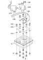
図13は、ヘッド10の背面を示しており、この図13には、電極8、9をヘッドへ結合するために使用されるコンポーネント、および電極8、9へ電気接続を提供するために使用されるコンポーネントも示されている。モータ1310は、モータ1310の出力に結合されている偏心輪1320を含めてヘッド10へ機械的振動を提供するために使用され、その結果、この装置は、電気的振動ならびに機械的振動の両方を同時に患者の皮膚へ提供する。機械的振動は、ほかの説明済みの本発明の実施態様に関して述べたとおり、好ましくは電気パルスと同期される。
FIG. 13 shows the back of the
電極8、9は、好ましくはヘッド10の正面プレート上に螺合される。ワッシャ1330およびねじ1340は、ワイヤ1350、1355と電極8、9を電気的に結合するために使用される。特にワイヤ1350(一端が、たとえば図4に示されているようなパルス・ジェネレータの2つの出力の一方へ結合される)は、中心電極9と電気的に接続され、ワイヤ1355(一端が、たとえば図4に示されているようなパルス・ジェネレータの2つの出力の他方へ結合される)は、周囲電極8と電気的に接続される。好ましい構成においては、抵抗1365がワイヤ1350と1355の間に介挿される。図13には、ねじ1380を介してヘッド10と結合されるハウジング1375も示されている。偏心輪1320は、ハウジング1375内において運動し、それによってプローブのヘッド10へ伝達される振動をもたらす。
The
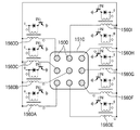
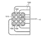
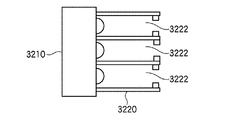
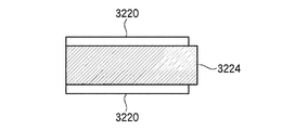
次に、図15および16を参照して本発明の第10の実施態様について説明する。第10の実施態様は、第9の実施態様に類似しているが、ヘッドについて異なる構成を使用していることをはじめ、複数のトランス(図4、4A、および4B参照)を備える点が異なる。図15は、プローブのヘッド1510上に配置されている電極1500の背面図を、図16は、電極1500の正面(皮膚側)図をそれぞれ示しており、それにおいては各電極が、それぞれの周囲を囲むグルーブまたはトラフ1530を有している。各グルーブ1530は、ヘッド1510の縁に達するアウトレットを有し、それにより、それぞれの管1550をそこへ嵌め込み、シリンジ6からグルーブ1530へ所定量の物質を供給することが可能になる。その場合、管1550は、ヘッド1510のトップ表面より上に達しない。図16に示されている多ポート管構成の変形として、多数の、電極の数に等しい数のシリンジを、それぞれのシリンジとそれぞれの電極を結合する管とともに備えることもできる。
Next, a tenth embodiment of the present invention will be described with reference to FIGS. The tenth embodiment is similar to the ninth embodiment except that it includes a plurality of transformers (see FIGS. 4, 4A, and 4B), including the use of different configurations for the head. . FIG. 15 shows a rear view of the
第10の実施態様においては、各電極1500がアクティブであり、それぞれ独自のパルス・トランス1560A〜1560Iと接続されている。シリンジ6からの物質は、それぞれの電極1500の周囲を囲むグルーブ1530へ供給される。電気パルスは、それぞれのパルス・トランス1560A〜1560Iからグルーブ1530へ供給され、それにおいては9電極構成の場合に、トランス1560C、1560E、1560G、および1560Iが、対応するそれぞれの電極へ正のパルスを提供し、同時にトランス1560A、1560B、1560D、1560F、および1560Hが、対応するそれぞれの電極へ負のパルスを提供する。より詳細に述べれば、トランス1560C、1560E、1560G、および1560Iは、それらの一次巻き線と二次巻き線が同相結合されており、トランス1560A、1560B、1560D、1560F、および1560Hは、それらの一次巻き線と二次巻き線が180度の位相差で結合されている(図15におけるこれらのトランスについて反対側に配置されたドットを参照されたい)。これらすべてのトランスの一次巻き線に対して同時に方形波が印加される場合には、ローからハイへの正の遷移が生じると、一次巻き線と二次巻き線が互いに同相結合されているトランスが正の指数型パルスを出力することになり、一次巻き線と二次巻き線が互いに180度の位相差で結合されているトランスが負の指数型パルスを出力することになる。
In the tenth embodiment, each
第10の実施態様においては、電極の第1のグループが正のパルスを受け取るときと、電極の第2のグループ(好ましくは、第1のグループと数において等しいか、ほぼ等しい)が負のパルスを受け取るときが同時となることが、良好な皮膚の毛孔拡張を提供する上で好ましい。パルスのタイプ、バースト持続時間、周波数等については、すでに説明済みの実施態様に類似である。また第10の実施態様は、前述した方法に従って、患者の皮膚への電気パルスの印加と同時に患者の皮膚へ印加される機械的振動を含むこともできる。 In a tenth embodiment, when the first group of electrodes receives a positive pulse, the second group of electrodes (preferably equal or nearly equal in number to the first group) is a negative pulse. It is preferred to provide good skin pore dilation at the same time. The type of pulse, burst duration, frequency, etc. are similar to the previously described embodiments. The tenth embodiment can also include mechanical vibration applied to the patient's skin simultaneously with the application of the electrical pulse to the patient's skin according to the method described above.
第11の実施態様においては、プローブのヘッド部分に配置されている複数の電極に対して電気パルスを出力するべく複数のトランスがそれぞれ備えられ、それにおいて複数のトランスは、対応するそれぞれの電極へ、別々の独立したパルスのバーストを提供する。たとえば、第11の実施態様におけるそれぞれのパルス・ジェネレータは、0度から360度までの範囲内において異なる位相シフト量を有することができる。これについて、トランスからの出力パルスは互いに同期され、互いに関して特定の位相ずれ関係を有する。 In the eleventh embodiment, a plurality of transformers are provided to output electric pulses to the plurality of electrodes arranged in the head portion of the probe, respectively, and the plurality of transformers are respectively connected to the corresponding electrodes. Provide separate and independent bursts of pulses. For example, each pulse generator in the eleventh embodiment can have a different amount of phase shift within a range from 0 degrees to 360 degrees. In this regard, the output pulses from the transformer are synchronized with each other and have a specific phase shift relationship with respect to each other.
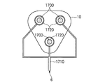
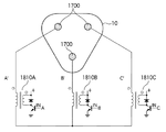
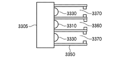
第11の実施態様に従った電極アレイの一例を図17、18、および19に示す。この例は、中心電極を伴わない3電極構成を提供する。まず図17を参照するが、この図はヘッド10の正面側を示しており、電極1700が、それぞれ管1710を介してシリンジ6と結合されており、それぞれの電極1700の周囲を囲むグルーブ1720内において物質を受け取る。前述の実施態様と同様に、図14に示されているとおり、ヘッド10の端まで延びているグルーブまたはパスが、そこへ管1710を滑り嵌めするために備えられ、その結果、管1710は、患者の皮膚と接触するヘッド10の上側表面(プレート)の上まで達しない。
An example of an electrode array according to the eleventh embodiment is shown in FIGS. This example provides a three-electrode configuration without a center electrode. First, referring to FIG. 17, this figure shows the front side of the
ここでヘッド10の背面を示した図18を参照すると、各トランス1810A、1810B、および1810Cが、極性は同一であるが、互いに特定量だけ遅延されているパルスを、それぞれのトランスと結合された電極1700の対応する1つへ提供している。図19は、それぞれのトランスへ供給される入力方形波パルスを示しており、それにおいてはトランス1810Cへ入力される方形波パルスが、トランス1810Bへ入力される方形波パルスに対して特定量(たとえば30度)だけ遅延されており、それもまたトランス1810Aへ入力される方形波パルスに対して特定量(たとえば30度)だけ遅延されている。これは、対応するそれぞれのトランス1810A、1810B、および1810Cへ適切なタイミングでトリガ『IN』信号を提供することによって容易に行うことができる。結果として、3つのパルス・ジェネレータのそれぞれから指数型パルスが出力されるが、それにおいてこれらの指数型パルスは、互いに関して一定量だけ位相シフトされている。
Referring now to FIG. 18, which shows the back of the
図17〜19に示されているような3電極3相ジェネレータ構成を用いる場合に、3つのパルス・ジェネレータによって出力される信号について、120度の位相シフト(たとえば、0度において出力される1つの信号、120度において出力される1つの信号、および240度において出力される1つの信号)を提供することが可能になる。これは、3相モータの回転に伴って生じるものに類似の態様の電界の回転を電極1700の間に提供する。より一般的に述べれば、当業者は、『n』個の電極および『n』個のパルス・ジェネレータを使用する第11の実施態様において、第11の実施態様に従った装置を介して治療される皮膚表面上に、所望の任意の特定タイプの電界分布を編み出すことが可能であると理解されることになろう。
When using a three-electrode three-phase generator configuration as shown in FIGS. 17-19, the signal output by the three pulse generators has a phase shift of 120 degrees (for example, one output at 0 degrees). Signal, one signal output at 120 degrees, and one signal output at 240 degrees). This provides an electric field rotation between
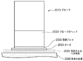
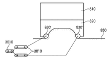
次に、図20を参照して第12の実施態様について説明する。第12の実施態様においては、プローブ2010が、皮膚吸収物質を皮膚へ提供するために使用される。それに関してプローブ2010は、この中ですでに説明した本発明の以前の実施態様のいずれかに従ったプローブとすることができる。図20に示されているとおり、プローブ2010は、振動ヘッド2020および振動ヘッド2020のエンド部分に備えられた電極アレイ2030を有する。第12の実施態様においては、プローブ2010のヘッド2020と患者の皮膚2040の間にガーゼ2033が備えられる。好ましくはガーゼ2033が、プローブ2010の振動ヘッド2020と同じサイズ(または実質的に同じサイズ)もしくはそれより大きいサイズを有するパッドであり、振動ヘッド2020が移動されると考えられる治療エリアをカバーする。好ましい具体化においては、ガーゼ2033が市販されているパッド(たとえば、厚さが0.1から1mmまでの間の矩形もしくは正方形)になる。ガーゼ2033をプローブ2010と患者の皮膚2040の間に備えた状態では、プローブ2010が患者の皮膚2040と直接触れない。ガーゼ2033は、患者の皮膚2040にわたってプローブ2010が容易に、かつガーゼ2033が用いられない場合に比べて少ない摩擦で移動できることを考慮に入れている。また発明者は、ガーゼ2033の使用が、患者の皮膚2040に対する皮膚吸収物質2035のより均質な塗布を提供することを発見した。ガーゼの代替として、そのほかのタイプの、コットン・ティッシュまたは合成(たとえばナイロン)ティッシュ等のパッドを、患者の皮膚2040とプローブ2010の間に使用してもよい。これらのパッドはすべて、プローブ2010の振動ヘッド2020(その中の容器)から(プローブ2010のヘッド2020内に皮膚吸収物質2035が蓄えられている実施態様について)パッド2033を通って患者の皮膚2040上へ、皮膚吸収物質2035が引き渡されることを可能にする充分な多孔性の特徴を有する。 Next, a twelfth embodiment will be described with reference to FIG. In the twelfth embodiment, probe 2010 is used to provide skin absorbing material to the skin. In that regard, probe 2010 may be a probe according to any of the previous embodiments of the invention already described herein. As shown in FIG. 20, the probe 2010 has a vibrating head 2020 and an electrode array 2030 provided at an end portion of the vibrating head 2020. In the twelfth embodiment, a gauze 2033 is provided between the head 2020 of the probe 2010 and the patient's skin 2040. Preferably, the gauze 2033 is a pad having the same size (or substantially the same size) or larger than the vibrating head 2020 of the probe 2010 and covers the treatment area where the vibrating head 2020 is considered to be moved. In a preferred embodiment, the gauze 2033 is a commercially available pad (eg, a rectangle or square between 0.1 and 1 mm thick). In a state where the gauze 2033 is provided between the probe 2010 and the patient's skin 2040, the probe 2010 does not directly touch the patient's skin 2040. The gauze 2033 takes into account that the probe 2010 can be easily moved across the patient's skin 2040 and with less friction than if gauze 2033 is not used. The inventors have also discovered that the use of gauze 2033 provides a more uniform application of skin absorbing material 2035 to the patient's skin 2040. As an alternative to gauze, other types of pads, such as cotton tissue or synthetic (eg nylon) tissue, may be used between the patient's skin 2040 and the probe 2010. All of these pads are on the patient's skin 2040 from the vibrating head 2020 (container therein) of the probe 2010 through the pad 2033 (for embodiments in which skin absorbing material 2035 is stored in the head 2020 of the probe 2010). It has sufficient porosity characteristics to allow skin absorbing material 2035 to be delivered.
第12の実施態様に従った本発明における重要な特徴は、プローブのヘッドと患者の皮膚の間にガーゼが備えられることである。1つの可能性のある具体化においては、ガーゼが、患者の皮膚ではなくプローブのヘッドへ添えられる。別の可能性のある具体化においては、ガーゼが、プローブのヘッドではなく患者の皮膚へ添えられる。いずれの具体化を用いても、皮膚への皮膚吸収物質のより均等な(ガーゼが使用されない場合と比較して)分布が得られ、同時に、より少ない(ガーゼが使用されない場合と比較して)摩擦を伴って患者の皮膚にわたるプローブのヘッドの(患者の皮膚の特定の領域を治療するための)移動を可能にする。第12の実施態様の1つの可能性のある具体化においては、医療用テープを用いるといった多様な、外すことのできる方法で患者の皮膚へガーゼを添えることが可能である。第12の実施態様の別の可能性のある具体化においては、ラバー・バンドを用いてガーゼ・パッドをプローブのヘッドへ留める(プローブのヘッドの側壁の周囲をラバー・バンドがグリップする)、もしくは粘着テープを用いてプローブのヘッドの側壁へガーゼ・パッドの周縁を接着する、あるいはプローブのヘッド上へのガーゼ・パッドの容易な嵌め込みおよび取り外しを可能にする外側(たとえばプラスチック製)シースをガーゼ・パッドに備えるといった多様な、外すことのできる方法でプローブのヘッドへガーゼを添えることが可能である。これらのいずれの場合においても、患者の皮膚から、もしくはプローブのヘッドからガーゼを容易に取り外し、使用後に廃棄することができる。 An important feature of the present invention according to the twelfth embodiment is that a gauze is provided between the probe head and the patient's skin. In one possible embodiment, gauze is attached to the probe head rather than to the patient's skin. In another possible embodiment, gauze is applied to the patient's skin rather than to the probe head. With either embodiment, a more even distribution of the skin-absorbing substance on the skin (compared to when gauze is not used) is obtained, and at the same time less (compared to when gauze is not used). Allows movement of the probe head (to treat specific areas of the patient's skin) across the patient's skin with friction. In one possible implementation of the twelfth embodiment, gauze can be applied to the patient's skin in a variety of removable ways, such as using medical tape. In another possible embodiment of the twelfth embodiment, a rubber band is used to fasten the gauze pad to the probe head (the rubber band grips around the side wall of the probe head), or Adhere the gauze pad rim to the probe head sidewall using adhesive tape, or an outer (eg, plastic) sheath that allows easy insertion and removal of the gauze pad onto the probe head. It is possible to attach gauze to the probe head in a variety of removable ways, such as preparing for a pad. In either of these cases, the gauze can be easily removed from the patient's skin or from the probe head and discarded after use.
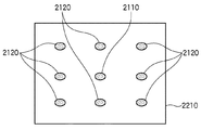
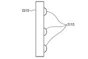
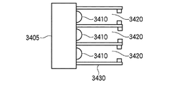
図21〜24を参照すると、第13の実施態様においては皮膚治療デバイスが、規定量のリドカイン、アスコルビン酸、もしくはそのほかの皮膚治療薬剤を皮膚内へ引き渡すべく構成される。第3の実施態様に関して説明したとおりの構成、すなわち中心電極2110および中心電極の周囲に配置される8つの周囲電極2120を伴い、中心電極2110がパルス・トランスの一方の出力へ接続され、8つの周囲電極2120がパルス・トランスの他方の出力へ接続される構成が可能なプローブのヘッド上において、プレート2210がヘッドと結合されており(図23および24参照)、電極2110および2120は、プローブのヘッド2130と患者の皮膚の間に備えられる。
Referring to FIGS. 21-24, in a thirteenth embodiment, a skin treatment device is configured to deliver a defined amount of lidocaine, ascorbic acid, or other skin treatment agent into the skin. A configuration as described with respect to the third embodiment, ie, with a
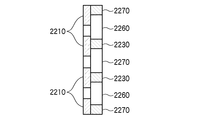
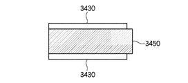
好ましくはプレート2210をプラスチック層(好ましい具体化においては厚さが300ミクロン)とし、ヘッド上に配置される9個の電極に対応する9個のホールが穿設される。プレートは、好ましくは60mm×60mmのトップ表面エリアを有する(トップ表面エリア上の異なるポイントに電極が配置される)。プラスチック層2210のトップには、非導体ラバーから作られた2つの同心正方形2230、2240が接着される(テーピング等のこのほかの接着方法も企図できるが、結局は本発明の範囲に帰する)。同心正方形2230、2240のそれぞれは、好ましくは5mmの幅および5mmの厚さを有する。外側の正方形2240と内側の正方形2230の間には、第1の(または外側)ガーゼ・パッド2260が嵌め込まれる。内側の正方形2230の内側には、第2の(または内側)ガーゼ・パッド2270が嵌め込まれる。したがって外側ガーゼ・パッド2260は8つの電極2120と接触し、内側ガーゼ・パッド2270は中心電極2110と接触する。内側の正方形2230は、内側ガーゼ・パッド2270と外側ガーゼ・パッド2260の間の電気的な分離を提供し、外側の正方形2240は、プレート2210のトップ表面に対して正しい位置に外側ガーゼ・パッド2270を保持する機能を提供する。内側ガーゼ・パッド2270および外側ガーゼ・パッド2260は、好ましくは内側の正方形2230および外側の正方形2240の厚さと同じ5mmの厚さを有する。
The
第13の実施態様の好ましい具体化においては、外側ガーゼ・パッド2240に約2mlの生理食塩水(1%のNaCl)を吸い込ませ、内側ガーゼ・パッドに0.5mlの5%塩酸リドカイン水溶液を吸い込ませる。プレート2210は、患者の皮膚とプローブの振動ヘッドの間に配置される。
In a preferred embodiment of the thirteenth embodiment, the
マウスに対して実施された実験では、マイクロ皮膚剥削治療の後に第13の実施態様に従ったシステムならびに方法によって、同じ電流×時間(『×』は乗算演算子)の積の値にセットされたイオン導入デバイスとの比較において同量の放射性リドカインが皮膚内へ渡されることが立証され、それにおいてはイオン導入デバイスの電流が、第1の正の相および第2の負の相において正となるようにセットされ、第13の実施態様に従ったシステムならびに方法の電流が、正のパルスの合計時間ごとのパルス当たりの積の平均電流がイオン導入デバイスの正の相と同じ値を持つように、かつ負のパルスの合計時間ごとのパルス当たりの積の平均電流がイオン導入デバイスの負の相と同じ値を持つようにセットされた。 In experiments conducted on mice, the same current x time ("x" is the multiplication operator) product value was set by the system and method according to the thirteenth embodiment after microdermabrasion treatment. It is demonstrated that the same amount of radioactive lidocaine is passed into the skin in comparison to the iontophoretic device, where the iontophoretic device current is positive in the first positive phase and the second negative phase. So that the current of the system and method according to the thirteenth embodiment is such that the average current of the product per pulse per total time of positive pulses has the same value as the positive phase of the iontophoresis device. And the average current of the product per pulse per total time of the negative pulse was set to have the same value as the negative phase of the iontophoresis device.
上記の実験は、第13の実施態様に従った本発明の利点を、イオン導入デバイスの使用との比較において立証した。本発明の1つの利点は、部分的には対称パルス電流の使用が貢献して電極に化学反応を生じないことである。これに対してイオン導入デバイスは、皮膚上におけるPHの変化を伴う電解を生じ、結果的にそれによって皮膚上に逆効果(たとえば、皮膚の赤み、皮膚の炎症、皮膚のやけど)をもたらす可能性がある。第13の実施態様に従った本発明の使用は、角質層(外気にさらされている皮膚の外側の層)を除去するマイクロ皮膚剥削を皮膚に施した後にその皮膚に対して皮膚吸収治療を提供することを可能にするが、イオン導入デバイスを使用して皮膚治療を提供すると、皮膚上にPHの変化を生じる場合には、より高いダメージをもたらす可能性がある。イオン導入デバイスに代えて本発明の第13の実施態様を使用するときにはこの問題が生じない。2つのテクニックをともに使用することによって(マイクロ皮膚剥削およびその後の第13の実施態様に従ったシステムまたは方法の使用による治療)、マウスに対する実験によって立証されたとおり、より高い皮膚治療物質のフロー(約50%の増加)が得られる。 The above experiments demonstrated the advantages of the present invention according to the thirteenth embodiment in comparison with the use of an iontophoretic device. One advantage of the present invention is that, in part, the use of a symmetric pulse current contributes and does not cause a chemical reaction at the electrode. In contrast, iontophoretic devices can cause electrolysis with changes in pH on the skin, which can result in adverse effects on the skin (eg, redness of the skin, skin irritation, skin burns). There is. The use of the present invention according to the thirteenth embodiment provides a skin absorption treatment for the skin after applying micro-dermabrasion to the skin to remove the stratum corneum (the outer layer of the skin exposed to the open air). While being able to provide, providing a skin treatment using an iontophoretic device may result in higher damage if it causes a change in PH on the skin. This problem does not occur when using the thirteenth embodiment of the present invention instead of an iontophoresis device. By using the two techniques together (treatment by micro-dermabrasion and subsequent use of the system or method according to the thirteenth embodiment), as demonstrated by experiments on mice, a higher skin treatment substance flow ( About 50% increase).
イオン導入デバイスと比較した場合の、第13の実施態様に従った本発明の追加のさらなる利点は、第13の実施態様に従った本発明が、皮膚治療物質として任意タイプのイオン化水性物質を使用する可能性を考慮に入れていることであり、塗布された物質の化学特性を変化させるリスク、したがって皮膚への逆効果をもたらすことのある電極における化学反応のリスクを伴わない。皮膚への逆効果の惹起は、イオン導入治療において生じ得る状況であり、そのため多くの物質の皮膚への塗布が阻害される。それに代えて第13の実施態様に従ったシステムまたは方法が使用されるときは、この問題を生じない。 An additional advantage of the present invention according to the thirteenth embodiment compared to the iontophoresis device is that the present invention according to the thirteenth embodiment uses any type of ionized aqueous material as a skin treatment material. The risk of changing the chemical properties of the applied material, and thus not the risk of chemical reactions at the electrode that can have adverse effects on the skin. Induction of adverse effects on the skin is a situation that can occur in iontophoretic treatment, which impedes the application of many substances to the skin. Instead, this problem does not occur when the system or method according to the thirteenth embodiment is used.
第13の実施態様の代替具体化においては、2つのガーゼ・パッドが2つのヒドロゲル・パッドと置き換えられ、外側パッドに1%のNaClが含められ、内側パッドに5%の塩酸リドカインが含められる。NaClのほかに、別のタイプの外側パッド用溶液として、このほかの水性イオン化導電性物質、あるいは、より大きい吸収表面を得るために、内側パッドに使用されている物質と同じ物質を含めることができる。塩酸リドカインのほかにも、別のタイプの内側パッド用の溶液として:アスコルビン酸、ジャルロン酸(jaluronic acid)、コラーゲン、エラスティン、コジック酸(cogic acid)、サリチル酸(salicilic acid)、リポソーム、消炎性ステロイド、あるいは局部麻酔剤を含めることができる。 In an alternative embodiment of the thirteenth embodiment, two gauze pads are replaced with two hydrogel pads, the outer pad contains 1% NaCl, and the inner pad contains 5% lidocaine hydrochloride. In addition to NaCl, another type of solution for the outer pad may include other aqueous ionized conductive materials, or the same materials used for the inner pad to obtain a larger absorbent surface. it can. In addition to lidocaine hydrochloride, as a solution for another type of inner pad: ascorbic acid, jaluronic acid, collagen, elastin, kogic acid, salicylic acid, liposome, anti-inflammatory steroid Alternatively, a local anesthetic can be included.
この実施態様の場合、パルスのバーストと同期された機械的振動の使用が、吸収レートの小さな増加をもたらし、さらに患者の、電流パルスによって生成される痛みに対する感覚を減少させ、それによって患者によって許容可能なパルス電流(すなわち、患者に身体的な不快感を生じさせないパルス電流レベル)を増加させることが可能になる。 In this embodiment, the use of mechanical vibrations synchronized with the burst of pulses results in a small increase in absorption rate, further reducing the patient's sensation of pain generated by the current pulse, thereby being tolerated by the patient. It is possible to increase the possible pulse current (ie the pulse current level that does not cause physical discomfort to the patient).
第13の実施態様については、前に説明した第3の実施態様に示されているような電極構成に関連して説明されているが、そのほかのタイプの電極構成を使用してもよく、その場合は、第1のセットの電極が、上に述べたような第1の溶液吸収パッドによって覆われ、第1のセットの電極と電気的に接続されていない第2のセットの電極が上に述べたような第2の溶液吸収パッドによって覆われる。 The thirteenth embodiment has been described in connection with the electrode configuration as shown in the third embodiment described previously, but other types of electrode configurations may be used, If the first set of electrodes is covered by a first solution absorbing pad as described above, and the second set of electrodes not electrically connected to the first set of electrodes is on top Covered by a second solution absorbent pad as described.
これまで述べてきたいくつかの皮膚吸収装置の実施態様を皮膚に対して実験的に適用した結果、物質の吸収の結果ならびにレートに顕著な変化が生じていることが立証された。市場で入手可能な標準的なマイクロ皮膚剥削を用いて前もって皮膚剥削が施された皮膚のエリアならびに前もって皮膚剥削が施されなかった隣接エリアにわたって分析を行った。この分析から、皮膚剥削を施したエリア内において得られた結果が、極めて一定かつ再現性があるのに対し、皮膚剥削を施さなかったエリアは、変動的であり、いくぶん一貫性に欠けていることが立証された。この不調和は、皮膚の角質層(角質化した、あるいは死んだ表皮の最外被層)が、皮膚へ塗布される物質の吸収に対するバリアとして作用し、さらにそれが皮膚の電気抵抗を増加させ、その結果、本発明に従った皮膚吸収治療の吸収効果をいくぶん低下させることに起因する。 Several skin absorption device embodiments described so far have been experimentally applied to the skin and have demonstrated significant changes in substance absorption results as well as rates. Analysis was performed over areas of skin that had been pre-skinned using standard micro-dermabrasion available on the market as well as adjacent areas that had not been pre-skinned. From this analysis, the results obtained in the skinned area were very constant and reproducible, whereas the areas that were not skinned were variable and somewhat inconsistent. It was proved. This incompatibility causes the stratum corneum of the skin (the keratinized or dead outer skin layer) to act as a barrier to the absorption of substances applied to the skin, which in turn increases the electrical resistance of the skin. As a result, this results from somewhat reducing the absorption effect of the skin absorption treatment according to the present invention.
角質層の厚さは、各個人によって異なり、さらに同一個人においても時間によって変動する。これが、本発明の各種実施態様に従った皮膚吸収装置の標準的な適用時間を見つけ出すことを困難にする変動性を惹起する。この理由から、本発明のさらに別の実施態様によれば、皮膚吸収治療方法が、皮膚吸収装置を適用する前にマイクロ皮膚剥削を施すことを含み、最初にマイクロ皮膚剥削を施さない実施態様に比較して、より一定かつ再現性のある結果を提供する。皮膚吸収治療に先行して行われるべきマイクロ皮膚剥削は、参照によりその全体がこれに援用されている米国特許第6,322,568号および米国特許第6,039,745号等のマティオリ・エンジニアリング(Mattioli Engineering,Ltd.)に譲渡された様々な米国特許に記述されているもの、あるいはそのほかのタイプの従来から知られている皮膚剥削治療とすることができる。 The thickness of the stratum corneum varies from individual to individual, and also varies with time in the same individual. This causes variability that makes it difficult to find a standard application time for skin absorption devices according to various embodiments of the present invention. For this reason, according to yet another embodiment of the present invention, the skin absorption treatment method includes an embodiment in which micro-dermabrasion is performed before applying the skin-absorbing device, and no micro-dermabrasion is performed first. In comparison, it provides more consistent and reproducible results. Micro-dermabrasion to be performed prior to skin absorption treatment is described in Mattiori Engineering, such as US Pat. No. 6,322,568 and US Pat. No. 6,039,745, which are hereby incorporated by reference in their entirety. It can be described in various US patents assigned to Mattioli Engineering, Ltd., or other types of conventionally known skin ablation treatments.
好ましくは、本発明の実施態様の1つに従った皮膚吸収増加デバイスを用いた治療がその後に施されることになるエリア内の皮膚の角質層を100ミクロンの厚さにわたって剥離するために、3分間の皮膚剥削治療が行われる。理想的に述べれば、皮膚剥削治療の完了の直後(たとえば5分以内)に皮膚吸収治療が行われる。当然ではあるが、このほかの皮膚剥削治療を施す時間的長さ、角質層を除去する深さ、および皮膚剥削治療から皮膚吸収治療までの時間間隔も企図されるが、前述したとおり、結局は本発明の範囲に帰する。 Preferably, in order to exfoliate the stratum corneum of the skin in an area to be subsequently treated with a skin absorption enhancing device according to one of the embodiments of the present invention over a thickness of 100 microns. A 3 minute dermabrasion treatment is performed. Ideally, the skin absorption treatment is performed immediately after completion of the dermabrasion treatment (eg, within 5 minutes). Of course, the length of time to apply other skin exfoliation treatments, the depth to remove the stratum corneum, and the time interval between skin exfoliation treatments and skin absorption treatments are also contemplated. Returning to the scope of the present invention.
次に、第14の実施態様について詳細に説明する。本発明の第14の実施態様は、皮膚吸収の増加ならびにセルライトの減少のための方法および装置に指向されており、前述した第5もしくは第8の実施態様の修正として使用することができる。第14の実施態様においては、発明者によって、セルライト減少の速さならびに効率を向上させるために、コントロールしながら皮膚表面およびセルライトならびに脂肪組織を有する皮膚表面の下側のエリアを暖めることが、皮膚へ(したがって、セルライトならびに脂肪組織を有する皮膚の下側の領域へ)導入されるべき物質の吸収レートを増加させることになると決定された。これは、結果として、患者のセルライトならびに脂肪組織のより迅速かつより効率的な減少をもたらしている。 Next, the fourteenth embodiment will be described in detail. The fourteenth embodiment of the present invention is directed to a method and apparatus for increased skin absorption and decreased cellulite and can be used as a modification of the fifth or eighth embodiment described above. In a fourteenth embodiment, the inventor warms the skin surface and the area underneath the skin surface with cellulite and adipose tissue in a controlled manner to improve the speed and efficiency of cellulite reduction, It was determined that this would increase the absorption rate of the substance to be introduced (hence cellulite as well as the area under the skin with adipose tissue). This has resulted in a faster and more efficient reduction of patient cellulite as well as adipose tissue.
皮膚を暖めることは、少なくとも2つの異なる方法でもたらすことができる:すなわち(a)プローブのヘッドに配置されたローラの間に配置される50Wの赤外線加熱ランプ、または(b)周波数13.54MHz、出力50Wの無線周波を使用し、プローブのヘッドに配置されたローラを経由してRFを皮膚に供給する。 Warming the skin can be effected in at least two different ways: (a) a 50 W infrared heating lamp placed between rollers placed in the probe head, or (b) a frequency of 13.54 MHz, Using RF with an output of 50 W, RF is delivered to the skin via a roller located on the probe head.
コントロールしながら皮膚を暖めることについて、限定の意図ではなく例示として述べれば、皮膚表面を好ましくは秒当たり5℃のレートで約50℃の温度まで暖める。より一般的に言えば、秒当たり2℃〜40℃のレートで45℃〜60℃の温度まで皮膚を暖めることができる。 By way of example, and not by way of limitation, of warming the skin under control, the skin surface is preferably warmed to a temperature of about 50 ° C. at a rate of 5 ° C. per second. More generally speaking, the skin can be warmed to a temperature of 45 ° C. to 60 ° C. at a rate of 2 ° C. to 40 ° C. per second.
無線周波を介して暖める場合には、無線周波を好ましくは連続波(CW)とするが、それに代えて、特定のデューティ・サイクル(たとえば20%から80%までの間)を有する波とすることもできる。代替構成においては、温度センサがプローブのヘッドに備えられ、皮膚がいつ所望の温度に到達するかについての決定を行う。所望の皮膚温度に到達すると、その所望の皮膚温度が維持されるように(したがって、上昇しないように)皮膚への熱供給がコントロールされる。たとえば、患者の皮膚が50℃になったことが検出されると無線周波がコントロールされ、それがCW信号からパルス信号へ切り替えられて皮膚へ印加される熱が少なくなり、皮膚の治療の間にわたってその所望の皮膚温度が維持される。 When warming via radio frequency, the radio frequency is preferably a continuous wave (CW), but instead a wave with a specific duty cycle (eg between 20% and 80%) You can also. In an alternative configuration, a temperature sensor is provided in the probe head to make a determination as to when the skin reaches the desired temperature. When the desired skin temperature is reached, the heat supply to the skin is controlled so that the desired skin temperature is maintained (and therefore does not rise). For example, when it is detected that the patient's skin has reached 50 ° C., the radio frequency is controlled, which is switched from a CW signal to a pulse signal to reduce the heat applied to the skin and during skin treatment. The desired skin temperature is maintained.
50Wの赤外線加熱ランプの使用のほかに、LED(発光ダイオード)もしくはレーザ・ダイオードをそれに代えて使用してもよく、また赤外線レンジに代えて、可視光レンジ(たとえば、300μm〜10μm)を使用してもよい。さらに、ランプのパワー出力が、必ずしも50Wである必要もない(たとえば、それを25W〜100Wの範囲内とすることができる)。 In addition to using a 50 W infrared heating lamp, an LED (light emitting diode) or laser diode may be used instead, and a visible light range (for example, 300 μm to 10 μm) is used instead of the infrared range. May be. Furthermore, the power output of the lamp need not necessarily be 50 W (eg, it can be in the range of 25 W to 100 W).
13.54MHz、50Wの無線周波信号の使用のほかに、0.5MHzから27MHzまでの無線周波をそれに代えて使用してもよく、またパワー出力についても、1から100Wまでのいずれかを使用することができる。低い無線周波は、皮膚表面の下のより深い部分を暖めることになり、高い無線周波は、皮膚表面の下のより浅い部分を暖めることになる。したがって、使用する特定の無線周波は、患者の、治療されることになるエリアに依存する。 In addition to the use of radio signals of 13.54 MHz and 50 W, radio frequencies of 0.5 MHz to 27 MHz may be used instead, and the power output is any of 1 to 100 W. be able to. A low radio frequency will warm the deeper part under the skin surface, and a high radio frequency will warm the shallower part under the skin surface. Thus, the particular radio frequency used depends on the patient's area to be treated.
ここで図25、26、および27を参照すると、第14の実施態様の1つの可能性のある具体化が示されている。赤外線発光ダイオード(LED)2510がプローブのヘッドに備えられており、それにおいてLED 2510は、振動プレート810の皮膚と対向する表面上に配置されている。皮膚が真空チャンバ820ならびに真空ポンプ855を介してプローブのヘッド内へ吸い込まれるとき、その皮膚850が、LED 2510を介して暖められ、それによって皮膚表面下のセルライト/脂肪組織が暖められる(可溶化を生じる)。プローブを介して物質が皮膚へ塗布されるとき、その物質は、暖められたセルライト/脂肪細胞へ容易にとりつくことができるようになり、それによってセルライト/脂肪細胞がより容易に患者によって代謝され、その結果、セルライトおよび脂肪が減少する。また図25、26、および27には、ローラ830のまわりに結合されたラバー・ベルト840も示されている。
Referring now to FIGS. 25, 26, and 27, one possible implementation of the fourteenth embodiment is shown. An infrared light emitting diode (LED) 2510 is provided in the probe head, where the
次に、図28、29、30、および31を参照すると、第14の実施態様の別の可能性のある具体化が示されている。図28、29、および30においては、ローラが導体ローラ830’になっており、それが、患者の皮膚へ印加されることになる電気パルスのバーストのための手段を提供する。また、これらの導体ローラ830’は、患者の皮膚へ直接印加される熱供給用の無線周波信号のためのメカニズムも提供する。ローラ830’は、好ましくは金属ローラもしくは導電性プラスチック・ローラとする。さらに図30には、同軸ケーブル3010も示されており、これらのケーブルが、プローブのヘッド上に配置されたローラ830’へ提供されることになる電気パルスのバーストならびに熱供給用の無線周波信号のための供給路を提供する。図31は、これらの信号をローラ830’へ供給できる1つの可能性のある方法を示しており、それにおいては無線周波ジェネレータ3110が無線周波信号を出力し、その後それが第1のフィルタ3120を通り、同軸ライン3010上に出力される。電気信号バースト・ジェネレータ3130は、電気パルスのバーストを出力し、その後それが第2のフィルタ3140を通り、同軸ライン3010上に出力される。第1のフィルタ3120は、電気パルスのバーストが無線周波ジェネレータ3110へ入り込むことを防止する帯域幅を有しており、第2のフィルタ3150は、熱供給用の無線周波信号が電気信号バースト・ジェネレータ3140へ入り込むことを防止する帯域幅を有している。電気信号バースト・ジェネレータ3140の1つの可能性のある回路実装は、たとえば図4に示されている。
Referring now to FIGS. 28, 29, 30, and 31, another possible implementation of the fourteenth embodiment is shown. In FIGS. 28, 29, and 30, the roller is a conductive roller 830 'that provides a means for a burst of electrical pulses to be applied to the patient's skin. These conductive rollers 830 'also provide a mechanism for a radio frequency signal for heat supply that is applied directly to the patient's skin. Roller 830 'is preferably a metal roller or a conductive plastic roller. Also shown in FIG. 30 are
前述した実施態様に関連して述べたとおり、電気パルスのバースト内の各電気パルスの好ましい周波数は、2500から3000Hzまでの間であり、したがって第1のフィルタ3120は、この特定の周波数レンジを遮断する(ただし、1MHzを超える周波数は通過させる)べく構成することができる。同様に第2のフィルタ3150は、1MHzを超える周波数レンジを遮断するが、より低い信号の通過を可能にするべく構成することができる(たとえば、ロー‐パス・フィルタ)。
As stated in connection with the previous embodiment, the preferred frequency of each electrical pulse within the burst of electrical pulses is between 2500 and 3000 Hz, so the
次に、図32A〜C、33A、33B、および33A〜Cを参照して本発明の第15の実施態様について説明する。この第15の実施態様は、患者の皮膚へ電気パルスおよび/または機械的振動を提供するプローブのヘッドに結合されるコンポーネントを経由して、患者の皮膚へ物質を供給する代替方法を提供する。これに関して、第15の実施態様は前述した第13の実施態様に類似しているが、皮膚治療物質を皮膚へ塗布する方法が異なる態様となる。 Next, a fifteenth embodiment of the present invention will be described with reference to FIGS. 32A to 32C, 33A, 33B, and 33A to 33C. This fifteenth embodiment provides an alternative method of delivering material to the patient's skin via a component coupled to the probe head that provides electrical pulses and / or mechanical vibrations to the patient's skin. In this regard, the fifteenth embodiment is similar to the thirteenth embodiment described above, but differs in the manner in which the skin treatment substance is applied to the skin.
図32Aは、ヘッド・アタッチメント3220に結合されたプローブのヘッド3210の横断面図を示している。ヘッド・アタッチメント3220は、好ましくはポリプロピレン(ブラスチック・コンポーネントとすることができる)から作られ、9つの円筒状開口3222を有し、その中に独立した9つの円筒状スポンジを嵌め込むことができる。図32Bは、ヘッド・アタッチメント3220の正面図を示しており、図32Cは、ヘッド・アタッチメント3220の円筒状開口3222の1つの横断面図を、円筒状開口3222内に円筒状スポンジ3224が嵌め込まれた状態として示している。円筒状スポンジの使用に代えて、コットン・ガーゼ、もしくはヒドロゲル・パッドを円筒状開口3222内へ嵌め込み、あるいはこれらのコンポーネントの組み合わせを使用することもできる(たとえば、3つをガーゼ・パッド、3つをスポンジ、3つをヒドロゲル・パッドとする)。アタッチメント・ヘッド3220は、プローブの正面に9つの電極が配置される場合について、9つの円筒状開口3220を有するものとして示されており、図32Aの側面図には、それらの電極3230のうちの3つが示されている(プローブの正面に備わる残りの電極はブロックされて示されていないが、9つの電極の配置については図2Cを参照されたい)。
FIG. 32A shows a cross-sectional view of a
プローブの正面に備わる9つの電極のそれぞれは、円筒状開口3222の一端に配置されており、それにおいてスポンジ3224は、図32Bにもっとも良好に示されているように、円筒状開口3222の他端からわずかに突出している。このようにスポンジは、このプローブを介して治療されることになる患者の皮膚上のエリアと接触するように構成されている。各スポンジ3222には、患者の皮膚へ塗布されることになる物質に浸漬され、たとえばヒドロゲル・パッドに4%のリドカインを吸い込ませることができる。電気パルス(これらは、間接的にスポンジ3222を経由して患者の皮膚と接続される)を介して患者の皮膚へ電気パルスが印加され、かつ/または機械的振動によって、スポンジ3222に供給された物質が患者の皮膚内へ容易に吸収される。
Each of the nine electrodes on the front of the probe is located at one end of a
好ましい構成においては、アタッチメント・ヘッド3220が使い捨てコンポーネントであり、患者の治療後に廃棄することができる。アタッチメント・ヘッド3220は、スナップ嵌め結合、あるいはほかの実施態様に関連して説明済みの別の方法等の多様な方法を用いてプローブのヘッド3210と取り外し可能に結合することができる。当然のことではあるが、プローブのヘッド3210上における電極の配置ならびに数が異なる場合には、その特定の配置に適合するべくアタッチメント3220上の開口の配置ならびに数が変更されることになる。
In a preferred configuration, the
図33Aおよび33Bは、第2のタイプの電極配置を示しており、それにおいては中心電極3310が中心に配置されたスポンジ3320の下側に備えられ、周囲電極3330が周囲に配置されたスポンジ3340の下側に備えられる。この構成においてはプローブのヘッド3305が円形であり、アタッチメント・ヘッド3350は、中心に配置されるスポンジ3320を収容するための内側円筒状開口3360、および周囲に配置されるスポンジ3340を収容するための外側円筒状開口3370を有する。図33Aは、アタッチメント・ヘッド3350が結合された状態のプローブのヘッド3305の横断面図を示しており、図33Bは、アタッチメント・ヘッド3350のそれぞれの開口の中にスポンジが嵌め込まれた状態のアタッチメント・ヘッド3350の正面図を示している。
FIGS. 33A and 33B show a second type of electrode arrangement, in which a
図34A〜34Cは、プローブのヘッド3405上における第3のタイプの電極配置を示している。この配置は、たとえば図17および18に示したものに対応しており、それにおいてはプローブのヘッド3405上に中心配置される電極が存在しない。この構成においては、アタッチメント・ヘッド3430の各3つの円筒状開口3420の下側に3つの電極3410が備えられており、アタッチメント・ヘッド3430は、たとえばポリプロピレンから作ることができる。円筒状開口3420のそれぞれには、患者の皮膚へ塗布される物質を吸い込ませたスポンジまたはガーゼを充填することができる。図34Aは、アタッチメント・ヘッド3430が取り外し可能に取り付けられた状態のプローブのヘッド3405の横断面図を示し、図34Bは、アタッチメント・ヘッド3430の正面図(開口3420内にスポンジが備えられていない状態)を示し、図34Cは、スポンジ3450が中に嵌め込まれた状態の円筒状開口3420の1つの横断面図を示している。
34A-34C illustrate a third type of electrode arrangement on the
以上、本発明の各種の実施態様について、本発明に従って説明してきた。ここで説明し、例示したテクニックならびに構造に対し、本発明の範囲から逸脱することなしに多くの修正および変形を行うことができる。したがって、ここで述べた装置は例示に過ぎず、本発明の範囲を制限しないものと理解されるべきである。たとえば、機械的振動の周波数および電気パルスのバーストの周波数は、いくつかの異なる実施態様に関連して説明したとおり、同一とすることもできれば、またそれらが互いの整数倍もしくは約数とすることもできる。したがって、たとえば50Hzの電気パルスのバースト周波数を100Hzの機械的振動とともに使用してもよく、その場合においても患者の皮膚の吸収度を増加し、敏感度を減少させる(たとえば、痛みを少なくする)効果が達成される。それに代えて、200Hzの電気パルスのバースト周波数を100Hzの機械的振動とともに使用してもよく、その場合においても吸収度を増加し、敏感度を減少させる効果が達成される。さらに、電極が配置されるプローブのプレートを、滅菌済みの使い捨て部品(たとえば、滅菌済みの容器から取り出した後にプローブのヘッドへ取り付けられる部品)とすることができる。この具体化においては、患者の治療を完了した後、使い捨てプレートをプローブから外して廃棄し、その後、別の患者を治療するために、新しい滅菌済みプレート(上に電極が備えられている)をプローブへ取り付ける。この種の具体化によって、それぞれの患者と直接接触するプローブの部分が、それぞれの患者の治療の後に廃棄されることから、異なる患者間の汚染が著しく低減される。 In the above, various embodiments of the present invention have been described according to the present invention. Many modifications and variations may be made to the techniques and structures described and illustrated herein without departing from the scope of the present invention. Accordingly, it should be understood that the devices described herein are exemplary only and do not limit the scope of the invention. For example, the frequency of mechanical vibrations and the frequency of bursts of electrical pulses can be the same as described in connection with several different embodiments, and they can be integer multiples or divisors of each other. You can also. Thus, for example, a burst frequency of 50 Hz electrical pulses may be used with 100 Hz mechanical vibrations, which still increases the patient's skin absorbency and decreases sensitivity (eg, reduces pain). The effect is achieved. Alternatively, a burst frequency of 200 Hz electrical pulses may be used with 100 Hz mechanical vibrations, in which case the effect of increasing the absorbency and decreasing the sensitivity is achieved. Further, the plate of the probe on which the electrodes are placed can be a sterile disposable part (eg, a part that is attached to the probe head after removal from the sterile container). In this embodiment, after completing the treatment of the patient, the disposable plate is removed from the probe and discarded, and then a new sterilized plate (with electrodes on it) is placed to treat another patient. Attach to the probe. This type of implementation significantly reduces contamination between different patients, since the portion of the probe that comes into direct contact with each patient is discarded after each patient's treatment.
1 モータ
2 スクリュー
3 スライド
4 フレーム
5 ピストン
6 シリンジ
7 パイプ(または管)
8 中心電極;電極
9 周囲電極
10 ヘッド
11 グルーブまたはトラフ
12 グルーブ
110 DC電気モータ
120 偏心輪
130 振動プレート
210 電極アレイ
220 電極;平行金属帯
230 円形電極
233 電極
235 第1の電気接続
237 電極
239 第2の電気接続
250 電気ライン
260 電気ライン
270 電気ライン
280 電気ライン
310 振動ヘッド
320 電極アレイ
330 皮膚
340 物質
400 パルス・ジェネレータ
410 トランス
420 一次巻き線
430 トランジスタ;スイッチング・トランジスタ
440 二次巻き線
450 電気抵抗
500 ハンド‐ヘルド・プローブ;プローブ
510 アウトレット
610 DC電流ジェネレータ
705 電極アレイ
710 チャンバ;ディスペンサまたはチャンバ
720 クリームまたはジェル;物質
740 ローラ;導体ローラ
760 液体注ぎ口
800 ヘッド;プローブのヘッド
810 振動プレート
820 真空チャンバ;電気接続
830 ローラ;露出された表面
830’ 導体ローラ
840 ベルト;ラバー・ベルト;施与ギャップ
845 パイプ
850 皮膚
855 真空ポンプ
1310 モータ
1320 偏心輪
1330 ワッシャ
1340 ねじ
1350 ワイヤ
1355 ワイヤ
1365 抵抗
1375 ハウジング
1380 ねじ
1500 電極
1510 ヘッド
1530 グルーブ;グルーブまたはトラフ
1550 管
1560A パルス・トランス
1560B パルス・トランス
1560C パルス・トランス
1560D パルス・トランス
1560E パルス・トランス
1560F パルス・トランス
1560G パルス・トランス
1560H パルス・トランス
1560I パルス・トランス
1700 電極
1710 管
1720 グルーブ
1810A トランス
1810B トランス
1810C トランス
2010 プローブ
2020 振動ヘッド
2030 電極アレイ
2033 ガーゼ;パッド
2035 皮膚吸収物質
2040 患者の皮膚
2110 中心電極
2120 周囲電極
2130 プローブのヘッド
2210 プラスチック層;プレート
2230 同心正方形;内側の正方形
2240 外側ガーゼ・パッド;外側の正方形;同心正方形
2260 外側ガーゼ・パッド;第1の(または外側)ガーゼ・パッド
2270 第2の(または内側)ガーゼ・パッド;内側ガーゼ・パッド
2510 赤外線発光ダイオード(LED)
3010 同軸ケーブル;同軸ライン
3110 無線周波ジェネレータ
3120 第1のフィルタ
3130 電気信号バースト・ジェネレータ
3140 第2のフィルタ
3150 第2のフィルタ
3210 プローブのヘッド
3220 アタッチメント・ヘッド;ヘッド・アタッチメント
3222 スポンジ;円筒状開口
3224 円筒状スポンジ
3230 電極
3305 プローブのヘッド
3310 中心電極
3320 中心に配置されたスポンジ
3330 周囲電極
3340 周囲に配置されたスポンジ
3350 アタッチメント・ヘッド
3360 内側円筒状開口
3370 外側円筒状開口
3405 プローブのヘッド
3410 電極
3420 円筒状開口
3430 アタッチメント・ヘッド
3450 スポンジ
1
8 Central electrode; Electrode 9 Peripheral electrode 10 Head 11 Groove or trough 12 Groove 110 DC electric motor 120 Eccentric ring 130 Vibration plate 210 Electrode array 220 Electrode; Parallel metal strip 230 Circular electrode 233 Electrode 235 First electrical connection 237 Electrode 239 First Two electrical connections 250 Electric line 260 Electric line 270 Electric line 280 Electric line 310 Vibrating head 320 Electrode array 330 Skin 340 Material 400 Pulse generator 410 Transformer 420 Primary winding 430 Transistor; Switching transistor 440 Secondary winding 450 Electrical resistance 500 hand-held probe; probe 510 outlet 610 DC current generator 705 electrode array 710 chamber; dispenser or chamber 720 cream or gel; substance 740 roller; conductor roller 760 liquid spout 800 head; probe head 810 vibration plate 820 vacuum chamber; electrical connection 830 roller; exposed surface 830 'conductor roller 840 belt; rubber belt; Gap 845 Pipe 850 Skin 855 Vacuum pump 1310 Motor 1320 Eccentric ring 1330 Washer 1340 Screw 1350 Wire 1355 Wire 1365 Resistance 1375 Housing 1380 Screw 1500 Electrode 1510 Head 1530 Pulse 15 60 Transformer 15・ Transformer 1560D Pulse transformer 1560E Pulse transformer 1560F Pulse transformer 1560G Pulse Transformer 1560H Pulse Transformer 1560I Pulse Transformer 1700 Electrode 1710 Tube 1720 Groove 1810A Transformer 1810B Transformer 1810C Trans 2010 Probe Probe 2020 Vibrating Head 2030 Electrode Array 2033 Gauze; Pad 2035 Skin Absorbing Material 12040 Electrode 2130 probe head 2210 plastic layer; plate 2230 concentric square; inner square 2240 outer gauze pad; outer square; concentric square 2260 outer gauze pad; first (or outer) gauze pad 2270 second ( Or inside) gauze pad; inside gauze pad 2510 infrared light emitting diode (LED)
3010 Coaxial cable;
Claims (29)
(a)前記物質を前記患者の皮膚表面上へ、(i)前記皮膚表面に対する電気パルスのバースト、および(ii)前記皮膚表面に対する振動を同時に提供するプローブのヘッドを介して塗布すること、
を包含し、それにおいて前記振動が、前記皮膚表面へ印加される電気パルスのバースト・レートと実質的に同一の周波数レート、前記同一の周波数レートの第1調波、および/または前記同一の周波数レートの第2調波において前記皮膚表面へ印加される治療方法。 A therapeutic method for providing a substance to be absorbed on a patient's skin, comprising:
(A) applying the substance onto the skin surface of the patient via (i) a burst of electrical pulses to the skin surface and (ii) a probe head that simultaneously provides vibration to the skin surface;
Wherein the vibration is substantially the same frequency rate as the burst rate of the electrical pulses applied to the skin surface, the first harmonic of the same frequency rate, and / or the same frequency. A treatment method applied to the skin surface at a second harmonic of the rate.
(a1)指数関数形状のパルスであって、隣り合うパルスに関して逆の極性を有する指数関数形状のパルスを獲得すること、および、
(a2)電気パルスのバースト内において前記指数関数形状のパルスを出力すること、
を包含する、請求項1に記載の治療方法。 Application of the burst of electrical pulses is
(A1) obtaining an exponential shaped pulse having an opposite polarity with respect to adjacent pulses; and
(A2) outputting the exponential shaped pulse within a burst of electrical pulses;
The treatment method of Claim 1 including this.
前記患者の皮膚を(i)無線周波信号、および(ii)ランプのうちの1つによって暖めること、
を含み、それにおいて前記治療方法が、前記患者の皮膚表面の下にあるセルライトもしくは脂肪組織を低減するためのものである、請求項1に記載の治療方法。 In addition, before applying the substance to the patient's skin,
Heating the patient's skin by one of (i) a radio frequency signal and (ii) a lamp;
The method of claim 1, wherein the method of treatment is for reducing cellulite or adipose tissue underlying the skin surface of the patient.
前記患者の皮膚へ前記物質を塗布するべく構成されたプローブ、
第1のバースト・レートにおいて電気パルスのバーストを生成するべく構成された電気信号パルス・ジェネレータ、
第1の振動レートにおいて機械的振動を生成するべく構成された機械的振動ジェネレータ、
前記プローブ上に配置され、かつ前記機械的振動ジェネレータと結合される振動プレートであって、前記患者の皮膚へ前記機械的振動を提供するべく構成された振動プレート、および、
前記プローブ上に配置され、かつ前記電気信号パルス・ジェネレータと結合される複数の電極であって、前記患者の皮膚へ前記電気パルスのバーストを提供するべく構成された複数の電極、
を包含し、それにおいて前記第1のバースト・レートが、前記第1の振動レートと等しいかもしくは実質的に等しい治療デバイス。 A device for treating a patient by applying a substance to the patient's skin,
A probe configured to apply the substance to the patient's skin;
An electrical signal pulse generator configured to generate a burst of electrical pulses at a first burst rate;
A mechanical vibration generator configured to generate mechanical vibrations at a first vibration rate;
A vibration plate disposed on the probe and coupled to the mechanical vibration generator, the vibration plate configured to provide the mechanical vibration to the patient's skin; and
A plurality of electrodes disposed on the probe and coupled to the electrical signal pulse generator, the plurality of electrodes configured to provide a burst of the electrical pulses to the patient's skin;
Wherein the first burst rate is equal to or substantially equal to the first vibration rate.
固定された無線周波において無線周波信号を生成するべく構成された無線周波ジェネレータ、および、
前記無線周波信号を前記患者の皮膚へ印加するための手段、
を包含する、請求項4に記載の治療デバイス。 further,
A radio frequency generator configured to generate a radio frequency signal at a fixed radio frequency; and
Means for applying the radio frequency signal to the skin of the patient;
The treatment device of claim 4, comprising:
(a)皮膚剥削装置を用いて前記皮膚表面の領域に皮膚剥削治療を施すこと、
(b)その後、前記皮膚内における吸収が意図された物質を前記皮膚に塗布すること、
(c)10から200Hzまでの間の振動を前記皮膚へ印加すること、および、
(d)周波数が50から15,000Hzまでの間、かつピーク電圧が5から200Vまでの間の電気パルスのバースト列を、前記皮膚上に置かれる電極のアレイへ印加すること、
を包含し、それにおいて前記電気パルスのバースト列および前記振動が、前記皮膚に塗布された前記物質の吸収を高めるために同時に前記皮膚へ印加される、治療方法。 A therapeutic method for increasing absorption of a substance provided on a patient's skin surface, comprising:
(A) performing a skin abrasion treatment on the skin surface area using a skin abrasion device;
(B) then applying to the skin a substance intended for absorption in the skin;
(C) applying vibrations between 10 and 200 Hz to the skin; and
(D) applying a burst train of electrical pulses with a frequency between 50 and 15,000 Hz and a peak voltage between 5 and 200 V to an array of electrodes placed on the skin;
Wherein the burst train of electrical pulses and the vibration are applied to the skin simultaneously to enhance absorption of the substance applied to the skin.
(e)前記ステップ(b)ならびに(c)を実行するとき、前記皮膚内における実質的に均等な吸収を提供するために、前記皮膚へ真空が印加されること、
を包含する、請求項8に記載の治療方法。 further,
(E) when performing steps (b) and (c), a vacuum is applied to the skin to provide substantially uniform absorption within the skin;
The treatment method of Claim 8 including this.
患者の皮膚の一部の皮膚剥削を行い、前記患者の皮膚から皮膚の上層を取り除くべく構成された皮膚剥削ユニット、
前記患者の皮膚へ物質を塗布するべく構成されたプローブ、
第1の振動周波数において前記患者の皮膚の前記部分へ振動を印加するべく構成された振動ユニット、および、
第1のバースト・レートにおいて前記患者の皮膚の前記部分へ電気パルスのバーストを印加するべく構成された電気パルス・バースト・ユニット、
を包含し、それにおいて前記電気パルスのバーストおよび前記振動が、前記プローブを介して前記皮膚に塗布された前記物質の吸収を高めるために同時に前記患者の皮膚の前記部分に提供される、治療デバイス。 A device for treating a patient,
An exfoliating unit configured to exfoliate a portion of a patient's skin and to remove an upper layer of skin from the patient's skin;
A probe configured to apply a substance to the patient's skin;
A vibration unit configured to apply vibration to the portion of the patient's skin at a first vibration frequency; and
An electrical pulse burst unit configured to apply a burst of electrical pulses to the portion of the patient's skin at a first burst rate;
A treatment device wherein the burst of electrical pulses and the vibration are simultaneously provided to the portion of the patient's skin to enhance absorption of the substance applied to the skin via the probe .
前記患者の皮膚の前記部分へ前記電気パルスのバーストおよび前記振動が提供されるとき、前記患者の皮膚の前記部分が前記プローブへ向かって吸引されるように、前記患者の皮膚の前記部分へ真空を印加するべく構成された真空ユニット、
を包含する、請求項15に記載の治療デバイス。 further,
A vacuum is applied to the portion of the patient's skin so that when the burst of electrical pulses and the vibration are provided to the portion of the patient's skin, the portion of the patient's skin is aspirated toward the probe. A vacuum unit configured to apply
The treatment device of claim 15, comprising:
前記プローブの皮膚と向かい合う表面上に備えられる複数の電極であって、前記電気パルス・バースト・ユニットと伝達可能に結合された複数の電極、
を包含する、請求項15に記載の治療デバイス。 further,
A plurality of electrodes provided on a surface of the probe facing the skin, the electrodes being communicatively coupled to the electrical pulse burst unit;
The treatment device of claim 15, comprising:
前記プローブ上に備えられ、前記患者の皮膚の前記部分上において転がるべく構成された少なくとも1つのローラ、
を包含する、請求項15に記載の治療デバイス。 further,
At least one roller provided on the probe and configured to roll on the portion of the patient's skin;
The treatment device of claim 15, comprising:
固定された無線周波において無線周波信号を生成するべく構成された無線周波ジェネレータ・ユニット、および、
前記無線周波信号を前記少なくとも1つのローラへ引き渡すべく構成された同軸ケーブル、
を包含し、それにおいて前記無線周波信号は、1MHzから27MHzまでの間であり、前記患者の皮膚の前記部分の下側の患者の領域を暖めるために使用される、請求項19に記載の治療デバイス。 further,
A radio frequency generator unit configured to generate a radio frequency signal at a fixed radio frequency; and
A coaxial cable configured to deliver the radio frequency signal to the at least one roller;
20. The treatment of claim 19, wherein the radio frequency signal is between 1 MHz and 27 MHz and is used to warm a patient area under the portion of the patient's skin. device.
(a)前記皮膚の領域に対して皮膚剥削を施すこと、
(b)ランプまたは無線周波信号を用いて前記皮膚を暖めること、
(c)プローブを用いて前記皮膚の前記領域へ機械的振動を印加すること、および、
(d)ステップ(c)において前記皮膚の前記領域へ機械的パルスが印加されるときと同時に前記プローブを用いて前記皮膚の前記領域へ電気パルスを印加すること、
を包含する方法。 A method for reducing skin cellulite, comprising:
(A) applying skin exfoliation to the skin area;
(B) warming the skin using a lamp or radio frequency signal;
(C) applying a mechanical vibration to the area of the skin using a probe; and
(D) applying an electrical pulse to the region of the skin using the probe at the same time as a mechanical pulse is applied to the region of the skin in step (c);
Including the method.
(e)ステップ(c)および(d)と同時に、前記プローブが前記皮膚の前記領域に沿って移動する間に、前記プローブにおいて、前記皮膚の前記領域の少なくとも一部を前記プローブへ向かって吸引する吸引力を生成すること、
を包含する、請求項21に記載の方法。 further,
(E) Simultaneously with steps (c) and (d), while the probe moves along the region of the skin, the probe draws at least a portion of the region of the skin toward the probe. Generating a suction force to
The method of claim 21, comprising:
ステップ(b)と(c)の間に、セルライト減少物質を前記皮膚へ塗布すること、
を包含し、それにおいては前記振動を印加するステップが、前記皮膚内における前記物質の吸収を高め、かつ
前記吸引力を生成するステップが、前記皮膚内において前記物質を均等に分布する、請求項22に記載の方法。 further,
Applying a cellulite reducing substance to the skin during steps (b) and (c);
Wherein applying the vibration enhances absorption of the substance in the skin and generating the suction force distributes the substance evenly in the skin. 23. The method according to 22.
前記患者の皮膚の部分を、前記患者の皮膚の前記部分の角質層を取り除くことによって治療するべく構成された皮膚剥削ユニット、
ランプまたは無線周波信号を介して前記患者の皮膚の前記部分の下側の前記患者の領域を暖めるための手段、
前記患者の皮膚の前記部分の下側のセルライトを減少する物質を前記患者の皮膚の前記部分へ引き渡すべく構成されたプローブ、
前記患者の皮膚の前記部分に対して機械的振動を印加するべく構成された振動ユニット、および、
前記患者の皮膚の前記部分に対して電気パルスのバーストを印加するべく構成された電気パルス・バースト印加ユニット、
を包含し、それにおいては前記電気パルスのバーストが前記患者の皮膚の前記部分に対して、前記機械的振動が前記患者の皮膚の前記部分に対して印加されるときと同時に、かつ前記患者の皮膚の前記部分が暖められるときと同時に印加されるデバイス。 A device for reducing patient cellulite,
An exfoliating unit configured to treat a portion of the patient's skin by removing the stratum corneum of the portion of the patient's skin;
Means for warming the patient area under the portion of the patient's skin via a lamp or radio frequency signal;
A probe configured to deliver a substance that reduces cellulite below the portion of the patient's skin to the portion of the patient's skin;
A vibration unit configured to apply mechanical vibrations to the portion of the patient's skin; and
An electrical pulse burst application unit configured to apply a burst of electrical pulses to the portion of the patient's skin;
Wherein the burst of electrical pulses is applied to the portion of the patient's skin, the mechanical vibration is applied to the portion of the patient's skin, and the patient's skin. A device that is applied simultaneously when the part of the skin is warmed.
前記プローブが前記患者の皮膚に沿って移動される間に、前記プローブにおいて、前記患者の皮膚の前記部分を前記プローブへ向かって吸引する吸引力を生成するべく構成された吸引ユニット、
を包含する、請求項24に記載のデバイス。 further,
A suction unit configured to generate a suction force in the probe that sucks the portion of the patient's skin toward the probe while the probe is moved along the patient's skin;
25. The device of claim 24, comprising:
(a)端面上に備えられた電極を有するプローブ・ヘッドであって機械的に振動することのできるプローブ・ヘッドへ、前記電極の上側にそれぞれ配置された複数の開口を有するアタッチメント・デバイスであって、前記複数の開口内に備えられる、薬剤が吸い込まされた複数の吸収ユニットを伴うアタッチメント・デバイスを嵌めること、および、
(b)前記患者の前記皮膚表面の上へ薬剤を、前記患者の皮膚内において前記薬剤の吸収を生じさせるために(i)電極を経由した前記皮膚表面に対する電気パルス、および(ii)前記機械的に振動するプローブ・ヘッドを介した前記皮膚表面に対する機械的振動のうちの少なくとも1つを提供する前記プローブ・ヘッドを介して塗布すること、
を包含する治療方法。 A therapeutic method for providing a substance to be absorbed on the skin surface of a patient comprising:
(A) An attachment device having a plurality of openings respectively disposed above the electrodes to a probe head having an electrode provided on an end face and capable of mechanical vibration. Fitting an attachment device with a plurality of absorption units into which the medicament has been inhaled provided in the plurality of openings; and
(B) a drug on the patient's skin surface, (i) an electrical pulse to the skin surface via an electrode to cause absorption of the drug in the patient's skin, and (ii) the machine Applying via the probe head providing at least one of mechanical vibrations to the skin surface via a probe head that vibrates in a mechanical manner;
A therapeutic method comprising:
複数の電極が配置されたヘッドを有するプローブ、
前記プローブの前記ヘッドに隣接して備えられた振動プレート、
複数の開口を有し、前記プローブの前記ヘッドへ取り外し可能に取り付けられるべく構成されたアタッチメント・デバイス、
前記アタッチメント・デバイスの前記複数の開口にそれぞれ適合するべく構成された複数の吸収ユニットであって、前記患者の皮膚へ塗布されるべき前記薬剤が吸い込まされている複数の吸収ユニット、
前記プローブ内に備えられ、前記複数の電極へ電気パルスのバーストを引き渡すべく構成されたパルス・ジェネレータ、および、
前記プローブ内に備えられ、前記プローブの前記ヘッドに機械的振動を発生させるべく構成された振動ユニット、
を包含する装置。 A device for transdermal administration of a drug to a patient's skin,
A probe having a head in which a plurality of electrodes are arranged;
A vibration plate provided adjacent to the head of the probe;
An attachment device having a plurality of openings and configured to be removably attached to the head of the probe;
A plurality of absorption units each adapted to fit into the plurality of openings of the attachment device, wherein the plurality of absorption units are inhaled with the medicament to be applied to the patient's skin;
A pulse generator provided in the probe and configured to deliver a burst of electrical pulses to the plurality of electrodes; and
A vibration unit provided in the probe and configured to generate mechanical vibrations in the head of the probe;
Including the device.
Applications Claiming Priority (1)
| Application Number | Priority Date | Filing Date | Title |
|---|---|---|---|
| US10/784,913 US7083580B2 (en) | 2001-04-06 | 2004-02-24 | Method and apparatus for skin absorption enhancement and transdermal drug delivery |
Publications (1)
| Publication Number | Publication Date |
|---|---|
| JP2005296629A true JP2005296629A (en) | 2005-10-27 |
Family
ID=34750462
Family Applications (1)
| Application Number | Title | Priority Date | Filing Date |
|---|---|---|---|
| JP2005047835A Withdrawn JP2005296629A (en) | 2004-02-24 | 2005-02-23 | Method and apparatus for cutaneous absorption enhancement and percutaneous drug delivery |
Country Status (6)
| Country | Link |
|---|---|
| US (3) | US7083580B2 (en) |
| EP (1) | EP1568395A1 (en) |
| JP (1) | JP2005296629A (en) |
| CN (1) | CN1721010A (en) |
| CA (1) | CA2498079A1 (en) |
| MX (1) | MXPA05002236A (en) |
Cited By (8)
| Publication number | Priority date | Publication date | Assignee | Title |
|---|---|---|---|---|
| JP2010525881A (en) * | 2007-04-27 | 2010-07-29 | エコー セラピューティクス, インコーポレイテッド | Skin permeation device for analyte detection or transdermal drug delivery |
| JP2013542035A (en) * | 2010-11-12 | 2013-11-21 | シネロン メディカル リミテッド | Method and device for soft tissue treatment |
| JP2013544175A (en) * | 2010-12-03 | 2013-12-12 | シネロン メディカル リミテッド | Method and apparatus for improving electrode skin contact |
| JP2015128599A (en) * | 2005-06-17 | 2015-07-16 | 日東電工株式会社 | Permeate delivery system and method of use |
| JP2016016030A (en) * | 2014-07-04 | 2016-02-01 | ヤーマン株式会社 | Cosmetic treatment apparatus |
| JP2017511234A (en) * | 2014-03-21 | 2017-04-20 | ロレアル | Skin care device combining sound waves and iontophoresis |
| KR20190103624A (en) * | 2018-02-28 | 2019-09-05 | 주식회사 제우기술 | Electrical stimulation device |
| WO2025205758A1 (en) * | 2024-03-27 | 2025-10-02 | 株式会社カネカ | Drug delivery device |
Families Citing this family (160)
| Publication number | Priority date | Publication date | Assignee | Title |
|---|---|---|---|---|
| US6641591B1 (en) | 1999-08-26 | 2003-11-04 | John H. Shadduck | Instruments and techniques for controlled removal of epidermal layers |
| US7496401B2 (en) * | 2001-04-06 | 2009-02-24 | Mattioli Engineering Ltd | Method and apparatus for skin absorption enhancement and transdermal drug delivery |
| US7083580B2 (en) * | 2001-04-06 | 2006-08-01 | Mattioli Engineering Ltd. | Method and apparatus for skin absorption enhancement and transdermal drug delivery |
| US6980854B2 (en) * | 2001-04-06 | 2005-12-27 | Mattioli Engineering Ltd. | Method and apparatus for skin absorption enhancement and transdermal drug delivery of lidocaine and/or other drugs |
| US7010343B2 (en) | 2001-04-06 | 2006-03-07 | Mattioli Engineering Ltd. | Method and apparatus for skin absorption enhancement and transdermal drug delivery |
| US7520875B2 (en) | 2001-04-06 | 2009-04-21 | Mattioli Engineering Ltd. | Method and apparatus for skin absorption enhancement and transdermal drug delivery |
| US7349733B2 (en) * | 2001-11-02 | 2008-03-25 | Ceramatel, Inc. | Iontophoretic drug delivery systems |
| US9283597B2 (en) * | 2002-12-02 | 2016-03-15 | Cfd Research Corporation | Miniaturized electrothermal flow induced infusion pump |
| CA2594231C (en) * | 2004-12-27 | 2016-04-19 | Standen Ltd. | Treating a tumor or the like with electric fields at different orientations |
| US8467868B1 (en) | 2005-04-26 | 2013-06-18 | University Of South Florida | Method of transdermal drug delivery |
| US7300409B2 (en) * | 2005-05-12 | 2007-11-27 | S.C. Johnson & Son, Inc. | Therapy patch |
| US10548659B2 (en) | 2006-01-17 | 2020-02-04 | Ulthera, Inc. | High pressure pre-burst for improved fluid delivery |
| US7967763B2 (en) | 2005-09-07 | 2011-06-28 | Cabochon Aesthetics, Inc. | Method for treating subcutaneous tissues |
| US9358033B2 (en) | 2005-09-07 | 2016-06-07 | Ulthera, Inc. | Fluid-jet dissection system and method for reducing the appearance of cellulite |
| US8518069B2 (en) | 2005-09-07 | 2013-08-27 | Cabochon Aesthetics, Inc. | Dissection handpiece and method for reducing the appearance of cellulite |
| US9011473B2 (en) | 2005-09-07 | 2015-04-21 | Ulthera, Inc. | Dissection handpiece and method for reducing the appearance of cellulite |
| US9486274B2 (en) | 2005-09-07 | 2016-11-08 | Ulthera, Inc. | Dissection handpiece and method for reducing the appearance of cellulite |
| US20070065515A1 (en) * | 2005-09-22 | 2007-03-22 | Key Douglas J | Methods and compositions for treating skin lines and wrinkles and improving skin quality |
| US20070232966A1 (en) * | 2005-11-30 | 2007-10-04 | Robert Applebaum | Apparatus for skin and muscle treatment |
| US7885793B2 (en) | 2007-05-22 | 2011-02-08 | International Business Machines Corporation | Method and system for developing a conceptual model to facilitate generating a business-aligned information technology solution |
| US9248317B2 (en) | 2005-12-02 | 2016-02-02 | Ulthera, Inc. | Devices and methods for selectively lysing cells |
| US8048089B2 (en) | 2005-12-30 | 2011-11-01 | Edge Systems Corporation | Apparatus and methods for treating the skin |
| US8133191B2 (en) * | 2006-02-16 | 2012-03-13 | Syneron Medical Ltd. | Method and apparatus for treatment of adipose tissue |
| US20080031833A1 (en) * | 2006-03-13 | 2008-02-07 | Oblong John E | Combined energy and topical composition application for regulating the condition of mammalian skin |
| US20070217199A1 (en) * | 2006-03-17 | 2007-09-20 | Light Dimensions, Inc. | Light-based dermal enhancing apparatus and methods of use |
| WO2007109136A2 (en) * | 2006-03-17 | 2007-09-27 | Light Dimensions, Inc. | Light-based enhancing apparatuses and methods of use |
| US9566088B2 (en) | 2006-03-29 | 2017-02-14 | Edge Systems Llc | Devices, systems and methods for treating the skin |
| US10172644B2 (en) | 2006-03-29 | 2019-01-08 | Edge Systems Llc | Devices, systems and methods for treating the skin |
| KR101039758B1 (en) | 2006-04-28 | 2011-06-09 | 젤티크 애스세틱스, 인코포레이티드. | Cryoprotectants for use with therapeutic devices for improved cooling of subcutaneous lipid-rich cells |
| US20080065176A1 (en) * | 2006-09-11 | 2008-03-13 | Rainbow Communications, Inc. | Vacuum and negative ions assisted phototheraphy device |
| US9132031B2 (en) | 2006-09-26 | 2015-09-15 | Zeltiq Aesthetics, Inc. | Cooling device having a plurality of controllable cooling elements to provide a predetermined cooling profile |
| US20080077201A1 (en) | 2006-09-26 | 2008-03-27 | Juniper Medical, Inc. | Cooling devices with flexible sensors |
| US8192474B2 (en) | 2006-09-26 | 2012-06-05 | Zeltiq Aesthetics, Inc. | Tissue treatment methods |
| USD585997S1 (en) | 2006-10-13 | 2009-02-03 | Light Dimensions, Inc. | Light-based dermal enhancing apparatus |
| WO2008060494A2 (en) * | 2006-11-09 | 2008-05-22 | Lumenis, Inc. | Apparatus and method for treating tissue |
| CN101120904B (en) * | 2006-11-13 | 2011-06-29 | 李复生 | Therapeutic device for cancer diseases |
| US20080177219A1 (en) * | 2007-01-23 | 2008-07-24 | Joshi Ashok V | Method for Iontophoretic Fluid Delivery |
| US8121696B2 (en) * | 2007-02-02 | 2012-02-21 | Rommel P. Vallero | Topical analgesia using electrical and vibration stimuli |
| US7930036B1 (en) | 2007-02-23 | 2011-04-19 | Pravin Joshi | Tactile application of herboelectrical stimulation to augment mammary glands |
| CN104069567A (en) * | 2007-03-19 | 2014-10-01 | 茵苏莱恩医药有限公司 | Drug delivery device |
| US8622991B2 (en) * | 2007-03-19 | 2014-01-07 | Insuline Medical Ltd. | Method and device for drug delivery |
| US8968221B2 (en) * | 2007-04-17 | 2015-03-03 | Bwt Property, Inc. | Apparatus and methods for phototherapy |
| US20080287839A1 (en) | 2007-05-18 | 2008-11-20 | Juniper Medical, Inc. | Method of enhanced removal of heat from subcutaneous lipid-rich cells and treatment apparatus having an actuator |
| US8523927B2 (en) | 2007-07-13 | 2013-09-03 | Zeltiq Aesthetics, Inc. | System for treating lipid-rich regions |
| CN101842132B (en) * | 2007-08-01 | 2013-06-12 | 西纳龙医药有限公司 | Method and device for collagen growth stimulation |
| EP3488833B1 (en) | 2007-08-21 | 2025-10-22 | Zeltiq Aesthetics, Inc. | Monitoring the cooling of subcutaneous lipid-rich cells, such as the cooling of adipose tissue |
| US8439940B2 (en) | 2010-12-22 | 2013-05-14 | Cabochon Aesthetics, Inc. | Dissection handpiece with aspiration means for reducing the appearance of cellulite |
| KR101527456B1 (en) * | 2007-11-05 | 2015-06-11 | 에프케이에이 디스트리뷰팅 코., 엘엘씨 디/비/에이 홈딕스, 엘엘씨 | Massage apparatus with heater |
| WO2009088884A1 (en) | 2008-01-04 | 2009-07-16 | Edge Systems Corporation | Apparatus and method for treating the skin |
| WO2009097451A1 (en) | 2008-01-29 | 2009-08-06 | Edge Systems Corporation | Apparatus and method for treating the skin |
| US8814836B2 (en) | 2008-01-29 | 2014-08-26 | Edge Systems Llc | Devices, systems and methods for treating the skin using time-release substances |
| US8882685B2 (en) * | 2008-05-27 | 2014-11-11 | Bwt Property, Inc. | Apparatus and methods for phototherapy |
| US20090299266A1 (en) * | 2008-06-02 | 2009-12-03 | Mattioli Engineering Ltd. | Method and apparatus for skin absorption enhancement and transdermal drug delivery |
| US8221411B2 (en) | 2008-07-28 | 2012-07-17 | Medtronic, Inc. | Systems and methods for cardiac tissue electroporation ablation |
| KR101013581B1 (en) * | 2008-08-06 | 2011-02-14 | 라종주 | Electric skin beauty machine |
| US8603073B2 (en) | 2008-12-17 | 2013-12-10 | Zeltiq Aesthetics, Inc. | Systems and methods with interrupt/resume capabilities for treating subcutaneous lipid-rich cells |
| US8167280B2 (en) * | 2009-03-23 | 2012-05-01 | Cabochon Aesthetics, Inc. | Bubble generator having disposable bubble cartridges |
| US20100274175A1 (en) * | 2009-04-22 | 2010-10-28 | Mattioli Engineering Ltd. | Method and apparatus for skin absorption enhancement and transdermal drug delivery |
| JP5519000B2 (en) | 2009-04-30 | 2014-06-11 | ゼルティック エステティックス インコーポレイテッド | Devices, systems, and methods for removing heat from fat-rich subcutaneous cells |
| AU2010280361B2 (en) | 2009-08-04 | 2015-10-08 | Pollogen Ltd. | Cosmetic skin rejuvination |
| US11096708B2 (en) | 2009-08-07 | 2021-08-24 | Ulthera, Inc. | Devices and methods for performing subcutaneous surgery |
| US9358064B2 (en) | 2009-08-07 | 2016-06-07 | Ulthera, Inc. | Handpiece and methods for performing subcutaneous surgery |
| US8523791B2 (en) * | 2009-08-11 | 2013-09-03 | Laboratoire Naturel Paris, Llc | Multi-modal drug delivery system |
| IT1395992B1 (en) * | 2009-10-27 | 2012-11-09 | Caccia | HEAD FOR ELECTROPORATION |
| US9386837B2 (en) * | 2009-10-29 | 2016-07-12 | Synoia Technologies Ltd. | Multi-application skin care system |
| RU2012123457A (en) * | 2009-11-16 | 2013-12-27 | Поллоген Лтд. | NON-INVASIVE FAT REMOVAL |
| US11590346B2 (en) | 2009-11-16 | 2023-02-28 | Pollogen Ltd. | Apparatus and method for cosmetic treatment of human mucosal tissue |
| US20110144725A1 (en) | 2009-12-11 | 2011-06-16 | Bwt Property, Inc. | Phototherapy Apparatus With Interactive User Interface |
| CA2787374A1 (en) | 2010-01-25 | 2011-07-28 | Zeltiq Aesthetics, Inc. | Home-use applicators for non-invasively removing heat from subcutaneous lipid-rich cells via phase change coolants, and associated devices, systems and methods |
| IT1400214B1 (en) * | 2010-05-25 | 2013-05-24 | Bonifacio | ELECTRO-DIFFUSER DEVICE FOR PHYSIOTHERAPY. |
| US8676338B2 (en) | 2010-07-20 | 2014-03-18 | Zeltiq Aesthetics, Inc. | Combined modality treatment systems, methods and apparatus for body contouring applications |
| TWI527577B (en) * | 2010-12-24 | 2016-04-01 | Ya Man Ltd | Skin care device |
| US10722395B2 (en) | 2011-01-25 | 2020-07-28 | Zeltiq Aesthetics, Inc. | Devices, application systems and methods with localized heat flux zones for removing heat from subcutaneous lipid-rich cells |
| EP2688634A1 (en) * | 2011-03-23 | 2014-01-29 | Bruce K. Redding, Jr. | Systems and methods for enhancing the delivery of compounds to skin pores using ultrasonic waveforms |
| US8768455B2 (en) * | 2011-06-13 | 2014-07-01 | Triune Ip Llc | Topical applicator |
| KR101273879B1 (en) * | 2011-08-19 | 2013-06-17 | (주)센트로닉스 | Electric module for skin irritation |
| KR200467410Y1 (en) * | 2011-08-19 | 2013-06-12 | (주)아모레퍼시픽 | Massage device for face |
| WO2013059706A1 (en) * | 2011-10-19 | 2013-04-25 | Neuro Resouce Group, Inc. | Electrode apparatus and method of manufacturing electrodes |
| KR101850129B1 (en) | 2012-01-16 | 2018-05-30 | 스위스 스파 시스템 엘티디. | Hand-held Device for Electrically Powered Skin Treatment |
| ITRE20120011A1 (en) * | 2012-02-16 | 2013-08-17 | Mantis S R L | ELECTROMEDICAL DEVICE |
| US9186490B2 (en) * | 2012-06-26 | 2015-11-17 | Franklin J. Chang | Skin treatment device |
| DE102012013534B3 (en) | 2012-07-05 | 2013-09-19 | Tobias Sokolowski | Apparatus for repetitive nerve stimulation for the degradation of adipose tissue by means of inductive magnetic fields |
| US9545523B2 (en) | 2013-03-14 | 2017-01-17 | Zeltiq Aesthetics, Inc. | Multi-modality treatment systems, methods and apparatus for altering subcutaneous lipid-rich tissue |
| US9844460B2 (en) | 2013-03-14 | 2017-12-19 | Zeltiq Aesthetics, Inc. | Treatment systems with fluid mixing systems and fluid-cooled applicators and methods of using the same |
| US10238812B2 (en) | 2013-03-15 | 2019-03-26 | Edge Systems Llc | Skin treatment systems and methods using needles |
| EP3437575B1 (en) | 2013-03-15 | 2021-04-21 | Edge Systems LLC | Devices and systems for treating the skin |
| EP2815787A3 (en) * | 2013-04-30 | 2015-04-08 | Bomedus GmbH | Electrode assembly and device for the treatment of pain |
| RU2016109788A (en) * | 2013-09-19 | 2017-10-24 | Конинклейке Филипс Н.В. | SKIN PROCESSING DEVICE USING RADIO FREQUENCY ELECTRIC CURRENT |
| ES2974899T3 (en) | 2014-01-31 | 2024-07-02 | Zeltiq Aesthetics Inc | Compositions and treatment systems for enhanced cooling of lipid-rich tissue |
| US20150250413A1 (en) * | 2014-03-07 | 2015-09-10 | eldeeN, LLC | Systems and apparatus for needle-penetration pain management |
| US10675176B1 (en) | 2014-03-19 | 2020-06-09 | Zeltiq Aesthetics, Inc. | Treatment systems, devices, and methods for cooling targeted tissue |
| USD777338S1 (en) | 2014-03-20 | 2017-01-24 | Zeltiq Aesthetics, Inc. | Cryotherapy applicator for cooling tissue |
| US9962220B2 (en) * | 2014-04-27 | 2018-05-08 | Lumenis Ltd. | Modular aesthetic treatment handpiece |
| US10952891B1 (en) | 2014-05-13 | 2021-03-23 | Zeltiq Aesthetics, Inc. | Treatment systems with adjustable gap applicators and methods for cooling tissue |
| US10935174B2 (en) | 2014-08-19 | 2021-03-02 | Zeltiq Aesthetics, Inc. | Stress relief couplings for cryotherapy apparatuses |
| US10568759B2 (en) | 2014-08-19 | 2020-02-25 | Zeltiq Aesthetics, Inc. | Treatment systems, small volume applicators, and methods for treating submental tissue |
| GB201415611D0 (en) | 2014-09-03 | 2014-10-15 | Univ Strathclyde | Apparatus for topical application of material |
| WO2016106396A1 (en) | 2014-12-23 | 2016-06-30 | Edge Systems Llc | Devices and methods for treating the skin using a rollerball or a wicking member |
| US10179229B2 (en) | 2014-12-23 | 2019-01-15 | Edge Systems Llc | Devices and methods for treating the skin using a porous member |
| US9861818B2 (en) * | 2014-12-31 | 2018-01-09 | Ziip, Llc | Method and device for electrical current treatment |
| US11969594B2 (en) | 2014-12-31 | 2024-04-30 | Ziip, Inc. | Electrical current stimulator apparatus |
| US11491342B2 (en) | 2015-07-01 | 2022-11-08 | Btl Medical Solutions A.S. | Magnetic stimulation methods and devices for therapeutic treatments |
| US20180001107A1 (en) | 2016-07-01 | 2018-01-04 | Btl Holdings Limited | Aesthetic method of biological structure treatment by magnetic field |
| US10695575B1 (en) | 2016-05-10 | 2020-06-30 | Btl Medical Technologies S.R.O. | Aesthetic method of biological structure treatment by magnetic field |
| US11266850B2 (en) | 2015-07-01 | 2022-03-08 | Btl Healthcare Technologies A.S. | High power time varying magnetic field therapy |
| EP4197517A1 (en) | 2015-07-08 | 2023-06-21 | HydraFacial LLC | Devices, systems and methods for promoting hair growth |
| KR101788301B1 (en) * | 2015-09-17 | 2017-10-20 | 주식회사 엘림텍 | Electroporation device and control method thereof |
| CN107645946A (en) * | 2015-10-13 | 2018-01-30 | 伊曼·沙菲路 | Smart Joint Care |
| US11154418B2 (en) | 2015-10-19 | 2021-10-26 | Zeltiq Aesthetics, Inc. | Vascular treatment systems, cooling devices, and methods for cooling vascular structures |
| US11253717B2 (en) | 2015-10-29 | 2022-02-22 | Btl Healthcare Technologies A.S. | Aesthetic method of biological structure treatment by magnetic field |
| FR3043332B1 (en) * | 2015-11-06 | 2019-05-10 | Seb S.A. | DEVICE FOR APPLYING A PRODUCT TO BE DISTRIBUTED ON THE SKIN OF A USER BY IONTOPHORESIS |
| US11504348B2 (en) * | 2015-12-15 | 2022-11-22 | L'oreal | Iontophoresis method of delivering vitamin C through the skin and iontophoresis device comprising: an electrode assembly including at least one electrode and an aqueous active agent |
| GB201522851D0 (en) * | 2015-12-23 | 2016-02-03 | Cutitronics Ltd | Apparatus for topical application of material |
| US10463531B2 (en) * | 2015-12-30 | 2019-11-05 | L'oreal | Iontophoresis massager |
| AU2017206118B2 (en) | 2016-01-07 | 2021-09-30 | Zeltiq Aesthetics, Inc. | Temperature-dependent adhesion between applicator and skin during cooling of tissue |
| US10765552B2 (en) | 2016-02-18 | 2020-09-08 | Zeltiq Aesthetics, Inc. | Cooling cup applicators with contoured heads and liner assemblies |
| WO2017189732A1 (en) | 2016-04-26 | 2017-11-02 | Textural Concepts, LLC | A method and apparatus for the treatment of cellulite with the combination of low level light, ultrasound, and vacuum |
| US11464993B2 (en) | 2016-05-03 | 2022-10-11 | Btl Healthcare Technologies A.S. | Device including RF source of energy and vacuum system |
| US11247039B2 (en) | 2016-05-03 | 2022-02-15 | Btl Healthcare Technologies A.S. | Device including RF source of energy and vacuum system |
| US11534619B2 (en) | 2016-05-10 | 2022-12-27 | Btl Medical Solutions A.S. | Aesthetic method of biological structure treatment by magnetic field |
| US11382790B2 (en) | 2016-05-10 | 2022-07-12 | Zeltiq Aesthetics, Inc. | Skin freezing systems for treating acne and skin conditions |
| US10555831B2 (en) | 2016-05-10 | 2020-02-11 | Zeltiq Aesthetics, Inc. | Hydrogel substances and methods of cryotherapy |
| US10682297B2 (en) | 2016-05-10 | 2020-06-16 | Zeltiq Aesthetics, Inc. | Liposomes, emulsions, and methods for cryotherapy |
| US10583287B2 (en) | 2016-05-23 | 2020-03-10 | Btl Medical Technologies S.R.O. | Systems and methods for tissue treatment |
| US10556122B1 (en) | 2016-07-01 | 2020-02-11 | Btl Medical Technologies S.R.O. | Aesthetic method of biological structure treatment by magnetic field |
| US12201704B2 (en) | 2016-07-25 | 2025-01-21 | Allan Danto | System and method for treating skin and areas proximate thereto |
| US11141219B1 (en) | 2016-08-16 | 2021-10-12 | BTL Healthcare Technologies, a.s. | Self-operating belt |
| CN106236087A (en) * | 2016-08-31 | 2016-12-21 | 苏州格林泰克科技有限公司 | A kind of glue-free biopotential electrode and electrode auxiliary device |
| KR101787736B1 (en) | 2016-11-09 | 2017-11-15 | (주)휴마코스 | Mask having massage function and mask system having the same |
| US11076879B2 (en) | 2017-04-26 | 2021-08-03 | Zeltiq Aesthetics, Inc. | Shallow surface cryotherapy applicators and related technology |
| KR102505417B1 (en) * | 2017-11-03 | 2023-03-03 | 엘지전자 주식회사 | Skin care device |
| USD870304S1 (en) * | 2018-01-04 | 2019-12-17 | Comper Chuangxiang (Beijing) Technology Co. | Beauty instrument |
| CN112789013A (en) | 2018-07-31 | 2021-05-11 | 斯尔替克美学股份有限公司 | Method, device and system for improving skin |
| US20210353210A1 (en) * | 2018-11-08 | 2021-11-18 | MEDIFORM ITALIA S.r.l. | Electric device for the skin allergy test |
| US11730668B2 (en) | 2020-06-29 | 2023-08-22 | Therabody, Inc. | Vibrating therapy system and device |
| US11219762B2 (en) | 2019-03-04 | 2022-01-11 | Vitality Concepts International Ltd. | Therapeutic device for female genital predictive permeation |
| US12558146B2 (en) | 2019-04-11 | 2026-02-24 | Btl Medical Solutions A.S. | Methods and devices for aesthetic treatment of biological structures by radiofrequency and magnetic energy |
| US12156689B2 (en) | 2019-04-11 | 2024-12-03 | Btl Medical Solutions A.S. | Methods and devices for aesthetic treatment of biological structures by radiofrequency and magnetic energy |
| EP3952984B1 (en) | 2019-04-11 | 2024-09-04 | BTL Medical Solutions a.s. | Devices for aesthetic treatment of biological structures by radiofrequency and magnetic energy |
| CN110876832A (en) * | 2019-11-19 | 2020-03-13 | 南京从景生物技术有限公司 | An electronic patch for transdermal drug delivery based on radio frequency radiator |
| US11291474B2 (en) | 2020-01-06 | 2022-04-05 | Ed F. Nicolas | Skin treatment tool applicator tip |
| US11878167B2 (en) | 2020-05-04 | 2024-01-23 | Btl Healthcare Technologies A.S. | Device and method for unattended treatment of a patient |
| JP2023515722A (en) | 2020-05-04 | 2023-04-13 | ビーティーエル ヘルスケア テクノロジーズ エー.エス. | Devices and methods for unattended care of patients |
| US12611545B2 (en) | 2020-05-04 | 2026-04-28 | Btl Healthcare Technologies A.S. | Device and method for unattended treatment of a patient |
| US11564863B2 (en) | 2020-06-29 | 2023-01-31 | Therabody, Inc. | Cooling attachment module for facial treatment device |
| CN115734778B (en) | 2020-06-29 | 2024-04-12 | 席拉博迪股份有限公司 | Vibration therapy systems and devices |
| BR102020023091A2 (en) * | 2020-11-12 | 2022-05-24 | Marcelo Martins Grasti | Iontophoresis device with mechanical vibration and wireless communication |
| USD976431S1 (en) | 2021-03-02 | 2023-01-24 | Therabody, Inc. | Facial treatment device |
| USD1004793S1 (en) | 2021-03-02 | 2023-11-14 | Therabody, Inc. | Facial treatment device |
| US12324500B2 (en) * | 2021-04-05 | 2025-06-10 | John H. Shadduck | Systems and methods for treating lips and skin |
| CA3231401A1 (en) | 2021-09-10 | 2023-03-16 | Hydrafacial Llc | Devices, systems and methods for treating the skin |
| USD1065551S1 (en) | 2021-09-10 | 2025-03-04 | Hydrafacial Llc | Skin treatment device |
| USD1016615S1 (en) | 2021-09-10 | 2024-03-05 | Hydrafacial Llc | Container for a skin treatment device |
| USD1116120S1 (en) | 2021-10-11 | 2026-03-03 | Hydrafacial Llc | Skin treatment device |
| USD1042807S1 (en) | 2021-10-11 | 2024-09-17 | Hydrafacial Llc | Skin treatment tip |
| CA3260012A1 (en) | 2021-10-13 | 2023-04-20 | Btl Medical Solutions A.S. | Devices for aesthetic treatment of biological structures by radiofrequency and magnetic energy |
| US11896816B2 (en) | 2021-11-03 | 2024-02-13 | Btl Healthcare Technologies A.S. | Device and method for unattended treatment of a patient |
| USD1112778S1 (en) | 2022-03-04 | 2026-02-10 | Hydrafacial Llc | Light therapy device for skin care |
| USD1084369S1 (en) | 2023-02-10 | 2025-07-15 | Hydrafacial Llc | Skin treatment tip |
| US20260097226A1 (en) | 2024-10-08 | 2026-04-09 | Btl Medical Solutions A.S. | Devices and methods for application of a magnetic field to the nervous system |
Family Cites Families (65)
| Publication number | Priority date | Publication date | Assignee | Title |
|---|---|---|---|---|
| GB1077143A (en) | 1964-09-30 | 1967-07-26 | Norman Alexander Macleod | Improvements in an applicator for use in the therapeutic treatment of skin |
| DE2242079A1 (en) | 1972-08-26 | 1974-03-07 | Bruns Dieter | DEVICE FOR THE SIMULTANEOUS APPLICATION OF MASSAGE MOVEMENTS AND THERAPEUTICALLY EFFECTIVE IRRITATION CURRENTS |
| US4141359A (en) | 1976-08-16 | 1979-02-27 | University Of Utah | Epidermal iontophoresis device |
| US4301794A (en) | 1978-10-18 | 1981-11-24 | Robert Tapper | Method for iontophoretic treatment |
| US5135479A (en) * | 1983-08-18 | 1992-08-04 | Drug Delivery Systems, Inc. | Programmable control and mounting system for transdermal drug applicator |
| US4822470A (en) | 1987-10-09 | 1989-04-18 | Baylor College Of Medicine | Method of and apparatus for cell poration and cell fusion using radiofrequency electrical pulses |
| DE3739563C1 (en) | 1987-11-22 | 1989-04-13 | Fresenius Ag | Infusion syringe pump |
| JP2706465B2 (en) | 1988-04-27 | 1998-01-28 | 株式会社寺西電機製作所 | Portable massage machine |
| US4887594A (en) | 1988-06-09 | 1989-12-19 | Louis Siegel | Vibratory medicator |
| EP0346513A1 (en) | 1988-06-15 | 1989-12-20 | Etama Ag | Assembly for electrotherapy |
| ATE177959T1 (en) | 1989-05-10 | 1999-04-15 | Drug Delivery Systems Inc | ELECTRICAL SYSTEM WITH MULTIPLE SIGNALS FOR TRANSDERMAL DRUG ADMINISTRATION |
| US5135478A (en) * | 1989-05-10 | 1992-08-04 | Drug Delivery Systems Inc. | Multi-signal electrical transdermal drug applicator |
| US5320597A (en) * | 1991-02-08 | 1994-06-14 | Becton, Dickinson And Company | Device and method for renewing electrodes during iontophoresis |
| MX9101782A (en) * | 1990-10-29 | 1992-06-05 | Alza Corp | IONTOPHORETICAL SUPPLY DEVICE AND METHOD TO HYDRATE THE SAME |
| US5158537A (en) * | 1990-10-29 | 1992-10-27 | Alza Corporation | Iontophoretic delivery device and method of hydrating same |
| US5688233A (en) | 1992-08-17 | 1997-11-18 | Genetronics, Inc. | Electronincorporation enhanced transdermal delivery of molecules |
| US6009345A (en) | 1992-08-17 | 1999-12-28 | Genetronics, Inc. | Method and apparatus for a combination of electroporation and iontophoresis for the delivery of drugs and genes |
| JPH0670987A (en) | 1992-08-28 | 1994-03-15 | Katsuro Tachibana | Medicine dosing and body liquid taking-out unit and device therefor |
| US5667487A (en) | 1993-04-07 | 1997-09-16 | Henley; Julian L. | Ionosonic drug delivery apparatus |
| US5415629A (en) | 1993-09-15 | 1995-05-16 | Henley; Julian L. | Programmable apparatus for the transdermal delivery of drugs and method |
| US5445611A (en) | 1993-12-08 | 1995-08-29 | Non-Invasive Monitoring Company (Nimco) | Enhancement of transdermal delivery with ultrasound and chemical enhancers |
| US6368333B2 (en) | 1994-06-29 | 2002-04-09 | Mattioli Engineering Ltd. | V-shaped handpiece for dermabrasion |
| JPH0866229A (en) | 1994-08-31 | 1996-03-12 | Matsushita Electric Works Ltd | Head blood circulation accelerator and head blood circulation acceleration method |
| US20030088205A1 (en) | 1994-09-07 | 2003-05-08 | Chandrasekaran Santosh Kumar | Electrotransport delivery of leuprolide |
| JP2964884B2 (en) | 1994-10-12 | 1999-10-18 | 株式会社毛髪クリニックリーブ二十一 | Hair growth device |
| US5879322A (en) * | 1995-03-24 | 1999-03-09 | Alza Corporation | Self-contained transdermal drug delivery device |
| US5624415A (en) | 1995-04-24 | 1997-04-29 | Alza Corporation | Reduction of skin irritation and resistance during electrotransport |
| US6039745A (en) | 1995-06-29 | 2000-03-21 | Mattioli Engineering Ltd. | Equipment for microdermoabrasion through a flow of air/reducing substances mix and relative handpiece |
| US6041253A (en) | 1995-12-18 | 2000-03-21 | Massachusetts Institute Of Technology | Effect of electric field and ultrasound for transdermal drug delivery |
| US6245347B1 (en) * | 1995-07-28 | 2001-06-12 | Zars, Inc. | Methods and apparatus for improved administration of pharmaceutically active compounds |
| US5983131A (en) | 1995-08-11 | 1999-11-09 | Massachusetts Institute Of Technology | Apparatus and method for electroporation of tissue |
| IT1286939B1 (en) | 1996-03-07 | 1998-07-24 | Umberto Mozzini | PORTABLE DEVICE FOR THE TRANSMISSION OF MECHANICAL VIBRATIONS AND ELECTRICAL EFFECTS ON THE EPIDERMIS |
| US5778894A (en) | 1996-04-18 | 1998-07-14 | Elizabeth Arden Co. | Method for reducing human body cellulite by treatment with pulsed electromagnetic energy |
| JPH10174704A (en) | 1996-10-18 | 1998-06-30 | Aisin Seiki Co Ltd | Massage equipment |
| US5830177A (en) | 1996-11-22 | 1998-11-03 | Anticancer, Inc. | Skin vibration method for topical targeted delivery of beneficial agents into hair follicles |
| US6104959A (en) | 1997-07-31 | 2000-08-15 | Microwave Medical Corp. | Method and apparatus for treating subcutaneous histological features |
| US6775569B2 (en) | 1997-11-05 | 2004-08-10 | Hisamitsu Pharmaceutical Co., Inc. | Electroporation device for in vivo delivery of therapeutic agents |
| US6022316A (en) | 1998-03-06 | 2000-02-08 | Spectrx, Inc. | Apparatus and method for electroporation of microporated tissue for enhancing flux rates for monitoring and delivery applications |
| US6007502A (en) | 1998-03-23 | 1999-12-28 | Worldra Co., Ltd. | Ion facial massage system |
| US6398753B2 (en) | 1998-04-03 | 2002-06-04 | Mcdaniel David H. | Ultrasound enhancement of percutaneous drug absorption |
| JP2002520101A (en) * | 1998-07-13 | 2002-07-09 | ジェネトロニクス、インコーポレーテッド | Method and apparatus for localized delivery of electrically assisted cosmetic agents |
| US6443914B1 (en) * | 1998-08-10 | 2002-09-03 | Lysonix, Inc. | Apparatus and method for preventing and treating cellulite |
| EP1163024B1 (en) | 1999-01-28 | 2003-12-17 | Cyto Pulse Sciences, Inc. | Delivery of macromolecules into cells |
| BR0008123A (en) | 1999-02-10 | 2001-11-13 | Gmp Drug Delivery Inc | Plaster-based device to increase local release of a treatment agent within target tissues, and the process of releasing a treatment agent into the target of a body vesicle |
| US6553253B1 (en) | 1999-03-12 | 2003-04-22 | Biophoretic Therapeutic Systems, Llc | Method and system for electrokinetic delivery of a substance |
| US6379324B1 (en) | 1999-06-09 | 2002-04-30 | The Procter & Gamble Company | Intracutaneous microneedle array apparatus |
| WO2001003638A1 (en) * | 1999-07-12 | 2001-01-18 | Dermispa Group, Inc. | Massage and toning device and method of use |
| US20030078499A1 (en) | 1999-08-12 | 2003-04-24 | Eppstein Jonathan A. | Microporation of tissue for delivery of bioactive agents |
| US7133717B2 (en) * | 1999-08-25 | 2006-11-07 | Johnson & Johnson Consumer Companies, Inc. | Tissue electroperforation for enhanced drug delivery and diagnostic sampling |
| EP1246665B1 (en) * | 2000-01-07 | 2005-08-24 | Biowave Corporation | Electrotherapy apparatus |
| US6592595B1 (en) | 2000-03-31 | 2003-07-15 | Edge Systems Corporation | Microdermabrasion and suction massage apparatus and method |
| US6271422B1 (en) | 2000-06-01 | 2001-08-07 | Abbott Laboratories | Method for fluoromethylation of alcohols via halogenative decarboxylation |
| US6517499B1 (en) | 2000-08-15 | 2003-02-11 | Mercedes R. Pereira | Massage device with rotating elements |
| ITPR20000068A1 (en) | 2000-12-19 | 2002-06-19 | Irene Cantoni | AESTHETIC TREATMENT EQUIPMENT. |
| US6687537B2 (en) | 2001-04-06 | 2004-02-03 | Mattioli Engineering Ltd. | Method and apparatus for skin absorption enhancement and cellulite reduction |
| US6748266B2 (en) | 2001-04-06 | 2004-06-08 | Mattioli Engineering Ltd. | Method and apparatus for skin absorption enhancement and transdermal drug delivery |
| US6980854B2 (en) | 2001-04-06 | 2005-12-27 | Mattioli Engineering Ltd. | Method and apparatus for skin absorption enhancement and transdermal drug delivery of lidocaine and/or other drugs |
| US6743215B2 (en) | 2001-04-06 | 2004-06-01 | Mattioli Engineering Ltd. | Method and apparatus for skin absorption enhancement and cellulite reduction |
| DE60123842T2 (en) | 2001-04-06 | 2007-09-06 | Mattioli Engineering Ltd. | DEVICE FOR IMPROVING THE ABSORPTION THROUGH THE SKIN |
| US7083580B2 (en) | 2001-04-06 | 2006-08-01 | Mattioli Engineering Ltd. | Method and apparatus for skin absorption enhancement and transdermal drug delivery |
| US7010343B2 (en) | 2001-04-06 | 2006-03-07 | Mattioli Engineering Ltd. | Method and apparatus for skin absorption enhancement and transdermal drug delivery |
| EP1450876B1 (en) | 2001-11-07 | 2016-08-17 | Syneron Medical Ltd. | Integrated transdermal drug delivery system |
| ES2271395T3 (en) * | 2002-02-23 | 2007-04-16 | Hwajin Cosmetics Co., Ltd. | TOTAL SKIN TREATMENT SYSTEM AND PROCEDURE USING THE SAME. |
| US7245963B2 (en) | 2002-03-07 | 2007-07-17 | Advisys, Inc. | Electrode assembly for constant-current electroporation and use |
| EP1583468A1 (en) * | 2002-12-16 | 2005-10-12 | Velcro Industries B.V. | Inflatable products and methods of their formation and use |
-
2004
- 2004-02-24 US US10/784,913 patent/US7083580B2/en not_active Expired - Lifetime
- 2004-10-14 US US10/963,565 patent/US7532926B2/en not_active Expired - Fee Related
-
2005
- 2005-02-21 EP EP05290385A patent/EP1568395A1/en not_active Withdrawn
- 2005-02-23 JP JP2005047835A patent/JP2005296629A/en not_active Withdrawn
- 2005-02-23 CA CA002498079A patent/CA2498079A1/en not_active Abandoned
- 2005-02-24 MX MXPA05002236A patent/MXPA05002236A/en active IP Right Grant
- 2005-02-24 CN CN200510071615.4A patent/CN1721010A/en active Pending
-
2006
- 2006-07-28 US US11/494,567 patent/US7376460B2/en not_active Expired - Fee Related
Cited By (10)
| Publication number | Priority date | Publication date | Assignee | Title |
|---|---|---|---|---|
| JP2015128599A (en) * | 2005-06-17 | 2015-07-16 | 日東電工株式会社 | Permeate delivery system and method of use |
| JP2010525881A (en) * | 2007-04-27 | 2010-07-29 | エコー セラピューティクス, インコーポレイテッド | Skin permeation device for analyte detection or transdermal drug delivery |
| JP2013063328A (en) * | 2007-04-27 | 2013-04-11 | Echo Therapeutics Inc | Skin permeation device for analyte sensing or transdermal drug delivery |
| JP2013542035A (en) * | 2010-11-12 | 2013-11-21 | シネロン メディカル リミテッド | Method and device for soft tissue treatment |
| JP2013544175A (en) * | 2010-12-03 | 2013-12-12 | シネロン メディカル リミテッド | Method and apparatus for improving electrode skin contact |
| JP2017511234A (en) * | 2014-03-21 | 2017-04-20 | ロレアル | Skin care device combining sound waves and iontophoresis |
| JP2016016030A (en) * | 2014-07-04 | 2016-02-01 | ヤーマン株式会社 | Cosmetic treatment apparatus |
| KR20190103624A (en) * | 2018-02-28 | 2019-09-05 | 주식회사 제우기술 | Electrical stimulation device |
| KR102123082B1 (en) * | 2018-02-28 | 2020-06-15 | 주식회사 제우기술 | Electrical stimulation device |
| WO2025205758A1 (en) * | 2024-03-27 | 2025-10-02 | 株式会社カネカ | Drug delivery device |
Also Published As
| Publication number | Publication date |
|---|---|
| MXPA05002236A (en) | 2006-04-27 |
| US20060264806A1 (en) | 2006-11-23 |
| CA2498079A1 (en) | 2005-08-24 |
| EP1568395A1 (en) | 2005-08-31 |
| US7083580B2 (en) | 2006-08-01 |
| US7376460B2 (en) | 2008-05-20 |
| US20040220622A1 (en) | 2004-11-04 |
| US7532926B2 (en) | 2009-05-12 |
| CN1721010A (en) | 2006-01-18 |
| US20050049642A1 (en) | 2005-03-03 |
Similar Documents
| Publication | Publication Date | Title |
|---|---|---|
| US7083580B2 (en) | Method and apparatus for skin absorption enhancement and transdermal drug delivery | |
| US7520875B2 (en) | Method and apparatus for skin absorption enhancement and transdermal drug delivery | |
| US7496401B2 (en) | Method and apparatus for skin absorption enhancement and transdermal drug delivery | |
| US6980854B2 (en) | Method and apparatus for skin absorption enhancement and transdermal drug delivery of lidocaine and/or other drugs | |
| US7471979B2 (en) | Method and apparatus for skin absorption enhancement and transdermal drug delivery | |
| US6748266B2 (en) | Method and apparatus for skin absorption enhancement and transdermal drug delivery | |
| KR101970644B1 (en) | Multifunctional skin treatment device for enhancement of transdermal delivery | |
| US6743215B2 (en) | Method and apparatus for skin absorption enhancement and cellulite reduction | |
| WO2003018117A2 (en) | Apparatus for skin enhancement and cellulite reduction | |
| US20090299266A1 (en) | Method and apparatus for skin absorption enhancement and transdermal drug delivery | |
| KR102759330B1 (en) | Multifunctional skin treatment device for enhancement of transdermal delivery | |
| US20150112300A1 (en) | Method for enhanced trans-tissue delivery of therapeutic substances | |
| JP2019500194A (en) | Electrokinetic transdermal and transmucosal delivery facilitator | |
| HK1095105B (en) | Method and apparatus for skin absorption enhancement and transdermal drug delivery of lidocaine and/or other drugs | |
| HK1073267A (en) | Method and apparatus for skin absorption enhancement and transdermal drug delivery | |
| HK1086208A (en) | Mathod and apparatus for skin absorption enhancement and transdermal drug delivery |
Legal Events
| Date | Code | Title | Description |
|---|---|---|---|
| A621 | Written request for application examination |
Free format text: JAPANESE INTERMEDIATE CODE: A621 Effective date: 20070525 |
|
| A761 | Written withdrawal of application |
Free format text: JAPANESE INTERMEDIATE CODE: A761 Effective date: 20090717 |
|
| A521 | Request for written amendment filed |
Free format text: JAPANESE INTERMEDIATE CODE: A821 Effective date: 20090717 |