JP2005296493A - Pachinko game machine - Google Patents
Pachinko game machine Download PDFInfo
- Publication number
- JP2005296493A JP2005296493A JP2004120200A JP2004120200A JP2005296493A JP 2005296493 A JP2005296493 A JP 2005296493A JP 2004120200 A JP2004120200 A JP 2004120200A JP 2004120200 A JP2004120200 A JP 2004120200A JP 2005296493 A JP2005296493 A JP 2005296493A
- Authority
- JP
- Japan
- Prior art keywords
- storage area
- display
- counter value
- stored
- counter
- Prior art date
- Legal status (The legal status is an assumption and is not a legal conclusion. Google has not performed a legal analysis and makes no representation as to the accuracy of the status listed.)
- Pending
Links
- 238000003860 storage Methods 0.000 claims abstract description 139
- 238000001514 detection method Methods 0.000 claims description 25
- 239000000725 suspension Substances 0.000 claims description 6
- 238000009826 distribution Methods 0.000 claims description 4
- 238000012545 processing Methods 0.000 abstract description 19
- 230000000694 effects Effects 0.000 description 40
- 239000004973 liquid crystal related substance Substances 0.000 description 6
- 238000000034 method Methods 0.000 description 6
- 238000004458 analytical method Methods 0.000 description 5
- 239000000758 substrate Substances 0.000 description 5
- 238000010586 diagram Methods 0.000 description 4
- 238000005259 measurement Methods 0.000 description 4
- 238000003780 insertion Methods 0.000 description 3
- 230000037431 insertion Effects 0.000 description 3
- 230000005540 biological transmission Effects 0.000 description 2
- 238000004364 calculation method Methods 0.000 description 2
- 239000011521 glass Substances 0.000 description 2
- 230000001174 ascending effect Effects 0.000 description 1
- 230000004397 blinking Effects 0.000 description 1
- 238000004590 computer program Methods 0.000 description 1
- 238000012937 correction Methods 0.000 description 1
- 238000004519 manufacturing process Methods 0.000 description 1
- 239000011159 matrix material Substances 0.000 description 1
- 239000010409 thin film Substances 0.000 description 1
Images


Landscapes
- Pinball Game Machines (AREA)
- Display Devices Of Pinball Game Machines (AREA)
Abstract
Description
この発明は、相互に識別可能な複数種類の識別情報を変動表示した後に確定表示された識別情報が所定の識別情報であった場合に大当りが発生するパチンコ機に関する。 The present invention relates to a pachinko machine in which a big hit is generated when identification information that is confirmed and displayed after variably displaying a plurality of types of identification information that can be distinguished from each other is predetermined identification information.
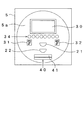
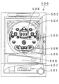
従来、この種のパチンコ機として、図11に示すパチンコ機が知られている。図11は、従来のパチンコ機の主要構成を示す正面説明図である。
パチンコ機500に設けられた発射レバー501を操作して発射された遊技球が、遊技盤502に設けられた第1種始動口503に入賞すると、パチンコ機500に備えられたCPUが、大当りカウンタ(たとえば、0〜952の計953個の大当りカウンタ値をカウントする)から大当りカウンタ値を1つ取得し、その取得した大当りカウンタ値が予め設定されている所定の大当り値(たとえば、7、277、293)の中のいずれかと同じである場合は大当りと判定し、いずれとも異なる場合はハズレと判定する(以下、大当りかハズレかの判定を大当り判定という)。続いてCPUは、特別図柄表示器504による特別図柄の変動パターンを複数の変動パターンの中から選択し、その選択した変動パターンの実行を特別図柄表示器504に指示する。これにより、特別図柄表示器504が、CPUにより指示された変動パターンに従って、複数の特別図柄(たとえば、0〜9の数字を示す10個の特別図柄)を縦方向に配列した図柄列を横方向の3つの表示領域においてそれぞれ上から下へ変動表示(スクロール表示ともいう)させる。
そして、特別図柄の変動表示の開始から所定時間経過すると、各表示領域における特別図柄の変動表示が停止し、上記大当り判定の結果に対応する停止図柄が各表示領域に確定表示される。つまり、大当り判定の結果が大当りであった場合は大当り図柄が表示され、ハズレであった場合はハズレ図柄が表示される。
Conventionally, a pachinko machine shown in FIG. 11 is known as this type of pachinko machine. FIG. 11 is a front explanatory view showing a main configuration of a conventional pachinko machine.
When a game ball launched by operating the launch lever 501 provided in the pachinko machine 500 wins the first type starting port 503 provided in the game board 502, the CPU provided in the pachinko machine 500 receives the big hit counter (For example, a total of 953 jackpot counter values from 0 to 952 are counted.) One jackpot counter value is acquired, and the acquired jackpot counter value is set to a predetermined jackpot value (for example, 7, 277). 293) is determined to be a big hit, and if it is different from any of them, it is determined to be a lost game (hereinafter, the determination of a big hit or a lost game is referred to as a big hit determination). Subsequently, the CPU selects a variation pattern of the special symbol by the special symbol display 504 from a plurality of variation patterns, and instructs the special symbol display 504 to execute the selected variation pattern. As a result, the special symbol display unit 504 horizontally arranges a symbol row in which a plurality of special symbols (for example, ten special
When a predetermined time elapses from the start of the special symbol variation display, the special symbol variation display in each display region is stopped, and the stop symbol corresponding to the result of the jackpot determination is fixedly displayed in each display region. That is, when the result of the big hit determination is a big hit, a big hit symbol is displayed, and when it is a loss, a lost symbol is displayed.
ここで、大当り図柄(たとえば、図11に示すような「777」)が表示されると大当りが発生し、扉式の開閉部材505が開作動し、大入賞口506が開口する。大入賞口506に遊技球が入賞すると、入賞球1個に付き、所定個数(たとえば、15個)の賞球が上受け皿507に払出される。また、大入賞口506に入賞した入賞球の数が所定数(たとえば、10個)に達するか、あるいは、大入賞口506が開口してから所定時間(たとえば、30秒)経過するかのいずれかの条件が満たされると、開閉部材505が閉作動し、大入賞口506が閉口する。さらに、大入賞口506に入賞した遊技球が大入賞口506の内部に設けられた特定領域508を通過すると、大入賞口506が連続して開口する権利が発生する。このように、大入賞口506が開口してから閉口するまでを1ラウンドとし、遊技球が特定領域508を通過することを条件として、複数のラウンド(たとえば、最大15ラウンド)の遊技を連続して行うことができる。以下、その遊技を大当り遊技という。
Here, when a big hit symbol (for example, “777” as shown in FIG. 11) is displayed, a big hit is generated, the door-type opening /
また、特別図柄の変動表示中、あるいは大当り遊技中に遊技球が第1種始動口503に入賞した場合は、その入賞による特別図柄の変動表示の開始は最大4回まで保留され、その入賞時にCPUが大当りカウンタから取得した大当りカウンタ値およびCPUが選択した変動パターンは、CPUがアクセスするRAMの記憶領域に記憶される。図12は記憶領域の構成を示す説明図である。CPUは、保留が発生する毎に記憶領域の保留順位1番から4番までの計4つの記憶領域に、大当りカウンタ値および変動パターンをそれぞれ保留順に記憶する。そして、CPUは、保留順(保留順位の番号が小さい順)に大当りカウンタ値および変動パターンを読出し、その読出したデータに従って特別図柄表示器504に特別図柄の変動表示を実行させる。
また、特別図柄の変動開始から確定表示までを1回の変動表示とした場合に、変動表示が1回終了する毎に保留数が1個減少し、保留順位が1つずつ繰り上がり、各保留順位に対応して記憶されている各データが自身の保留順位よりも1つ若い順位の記憶領域へ移動し、その移動先の記憶領域に記憶されているデータに上書きされる。
保留の数(以下、保留数という)は、4個のLEDから構成される保留数表示LED509の点灯数により表示される。
In addition, if the game ball wins the first type start port 503 during the special symbol fluctuation display or the big hit game, the start of the special symbol fluctuation display due to the winning is suspended up to four times. The jackpot counter value obtained by the CPU from the jackpot counter and the variation pattern selected by the CPU are stored in a storage area of the RAM accessed by the CPU. FIG. 12 is an explanatory diagram showing the configuration of the storage area. The CPU stores the jackpot counter value and the variation pattern in the order of the hold in the total of four storage areas from the
In addition, if the display from the start of change of the special symbol to the final display is changed once, the number of holds will decrease by 1 each time the change display ends, and the hold order will be increased by one. Each data stored corresponding to the rank moves to a storage area one rank lower than its own holding rank, and the data stored in the destination storage area is overwritten.
The number of holdings (hereinafter referred to as the holding number) is displayed by the number of lighting of the holding
ところで、上記パチンコ機500のように、特別図柄表示器が1つ設けられており、保留数の上限が4個に設定された第1種始動口を1つ備えた仕様を長年に亘って続けてきたため、遊技者に飽きられてきた。
そこで本願発明者は、保留数の上限がそれぞれ4個に設定された第1種始動口を2つ設け、各第1種始動口に対応した専用の特別図柄表示器を計2つ設けたパチンコ機を開発した。
By the way, like the pachinko machine 500, one special symbol display is provided, and the specification including one
Therefore, the inventor of the present application provides two first-type start ports each having an upper limit of the number of holdings set to four, and two special symbol displays corresponding to each first-type start port. A machine was developed.
しかし、図12に示した記憶領域を保留順位8番までのデータを記憶できるように拡張し、2つの第1種始動口のうち、いずれかに入賞する毎に大当りカウンタ値および変動パターンを保留順に記憶領域に記憶していくと、記憶されているデータがどの第1種始動口に入賞したときに記憶されたものか識別できなくなるため、記憶されているデータに対応するコマンドを特別図柄表示器を制御する制御基板へ送信した場合、その制御基板は受信したコマンドに基づいてどちらの特別図柄表示器を制御すればよいか判定できなくなってしまうという問題が発生した。
また、保留数が5個以上になっているときに保留順位を繰り上げると、データの移動処理を5個以上の記憶領域において実行しなければならないため、保留数の上限が4個であった従来と比べると、CPUの処理負担が増大するという問題も発生した。
However, the storage area shown in FIG. 12 has been expanded to store data up to the holding order No. 8, and the big hit counter value and the fluctuation pattern are held every time one of the two first-type starting ports wins. If it is stored in the storage area in order, it will not be possible to identify which
Further, if the holding order is increased when the number of holdings is five or more, the data movement process must be executed in five or more storage areas, so the upper limit of the number of holdings is four in the prior art As compared with the above, there is a problem that the processing load of the CPU increases.
そこでこの発明は、上述の諸問題を解決するためになされたものであり、記憶領域に記憶されているデータが、複数の第1種始動口のうち、どの第1種始動口に入賞したときに記憶されたデータであるか判定することができ、かつ、記憶領域に記憶されているデータの移動処理量を減少させることができるパチンコ機を実現することを目的とする。 Accordingly, the present invention has been made to solve the above-described problems, and when the data stored in the storage area wins a first type start port among a plurality of first type start ports. An object of the present invention is to realize a pachinko machine that can determine whether or not the data is stored in the storage area and can reduce the amount of movement processing of the data stored in the storage area.
この発明は、上記目的を達成するため、請求項1に記載の発明では、遊技球を発射する遊技球発射装置により発射された遊技球が、遊技盤面上の遊技領域に設けられた所定の領域を通過したことを検出して検出信号を出力する検出手段と、前記検出信号が出力されたときにカウンタからカウンタ値を取得し、その取得したカウンタ値が大当りに相当するカウンタ値であるか否かにより大当りかハズレかを判定する判定手段と、前記遊技球が前記所定の領域を通過した場合に、相互に識別可能な複数種類の識別情報を変動表示した後に前記判定手段の判定結果に対応する識別情報を確定表示するとともに、前記変動表示を行っている途中で前記遊技球が前記所定の領域を通過した場合は、その通過による前記変動表示を保留する表示装置とを備えており、前記表示装置は、前記識別情報の変動開始から確定表示までを1回の変動表示とした場合に、前記変動表示を行っている場合は、その変動表示が終了した後に、前記保留を行った数と同じ回数分の変動表示を行うことが可能なパチンコ機において、前記所定の領域が前記遊技領域に複数設けられており、前記検出手段が前記所定の領域毎に設けられており、前記保留が発生した順番を示す順番情報と、前記保留が発生したときに前記カウンタから取得したカウンタ値とを含むグループ情報をグループ単位で記憶可能な記憶領域を前記所定の領域と対応付けて複数ずつ有する複数の記憶領域グループと、前記検出手段から出力された検出信号が、どの検出手段から出力されたかの出力判定を行い、前記グループ情報を、前記順番に従うとともに前記出力判定の結果と対応付けて各記憶領域グループに振り分ける振分手段と、前記表示装置が、いずれかの記憶領域グループに記憶されている前記グループ情報を用いて前記変動表示を行った場合に、その用いられたグループ情報が記憶されていた記憶領域グループの中において前記用いられたグループ情報の順番の次の順番で記憶されていた他のグループ情報を、前記用いられたグループ情報が記憶されていた記憶領域に移動する移動手段とを備えたという技術的手段を用いる。
In order to achieve the above object, according to the first aspect of the present invention, in the invention according to
たとえば、後述の最良の形態に係るパチンコ機1は、第1種始動口21,22(所定の領域)と、第1種始動口21,22に入賞した遊技球を検出して検出信号をそれぞれ出力する第1種始動口スイッチ21a,22a(検出手段)と、保留が発生した順番を示す入賞順カウンタ値と、大当りカウンタ(カウンタ)から取得した大当りカウンタ値(カウンタ値)とを含む始動入賞データ(グループ情報)をグループ単位で記憶可能な第1記憶領域〜第4記憶領域を第1種始動口21,22に対応付けて有する記憶領域グループA、B(複数の記憶領域グループ)とを備える。
また、メインCPU112は、第1種始動口処理(図7)において、第1種始動口スイッチ21a,22aのどちらから出力された検出信号であるかを判定し、始動入賞データを上記順番に従うとともに、上記判定の結果と対応付けて記憶領域グループAまたはBに振り分ける(振分手段)。また、メインCPU112は、特別図柄処理(図8〜図10)において、記憶領域グループAの第1記憶領域に記憶されている始動入賞データを用いて変動表示を行った場合は、記憶領域グループAの第2記憶領域に記憶されている始動入賞データを記憶領域グループAの第1記憶領域に移動する(移動手段)。また、記憶領域グループBの第1記憶領域に記憶されている始動入賞データを用いて変動表示を行った場合は、記憶領域グループBの第2記憶領域に記憶されている始動入賞データを記憶領域グループBの第1記憶領域に移動する(移動手段)。なお、上記括弧内の記載は、請求項1の記載に対応するものである。
For example, the
Further, the main CPU 112 determines which one of the first type start port switches 21a and 22a is the detection signal output in the first type start port processing (FIG. 7), and follows the start winning data in the above order. Then, it is allocated to the storage area group A or B in association with the result of the determination (distribution means). When the main CPU 112 performs variable display using the start winning data stored in the first storage area of the storage area group A in the special symbol processing (FIGS. 8 to 10), the storage area group A The start winning data stored in the second storage area is moved to the first storage area of the storage area group A (moving means). In addition, when the variable display is performed using the start winning data stored in the first storage area of the storage area group B, the start winning data stored in the second storage area of the storage area group B is stored in the storage area. Move to the first storage area of group B (moving means). Note that the description in parentheses corresponds to the description in
振分手段が、検出手段から出力された検出信号が、どの検出手段から出力されたかの出力判定を行い、グループ情報を、順番に従うとともに出力判定の結果と対応付けて各記憶領域グループに振り分けるため、各グループ情報に対応付けられている出力判定の結果を解析すれば、どの所定の領域を通過したときに記憶されたグループ情報であるか判定することができる。
しかも、移動手段が、その用いられたグループ情報が記憶されていた記憶領域グループの中において上記用いられたグループ情報の順番の次の順番で記憶されていた他のグループ情報を、上記用いられたグループ情報が記憶されていた記憶領域に移動する。
つまり、変動表示に用いられたグループ情報が記憶されていた記憶領域グループの中でのみグループ情報の移動を行うことができるため、その移動を行うCPUの処理量を減少させることができる。
In order for the allocating unit to determine the output of which detection unit the detection signal output from the detection unit is output, and to distribute the group information to each storage area group in accordance with the order and the output determination result, By analyzing the output determination result associated with each group information, it is possible to determine which predetermined region the group information is stored when passing through.
Moreover, the moving means used the other group information stored in the order next to the used group information in the storage area group in which the used group information was stored. Move to the storage area where the group information was stored.
That is, the group information can be moved only within the storage area group in which the group information used for the variable display is stored, so that the processing amount of the CPU that performs the movement can be reduced.
[全体の主要構成]
まず、この実施形態のパチンコ機の主要構成について図1および図2を参照して説明する。図1は、そのパチンコ機の外観を正面から見た説明図である。図2は図1に示すパチンコ機に備えられた遊技盤を正面から見た概略説明図である。
図1に示すように、パチンコ機1には、外殻を構成する外枠2が設けられており、その外枠2にはガラス枠3が開閉可能に取付けられている。ガラス枠3の内側には遊技盤5が設けられており、外枠2の前面右下方には、遊技盤5へ遊技球を発射する発射装置を操作する発射レバー15aが回動可能に取付けられている。遊技盤5の下方には、払出された賞球や貸球を収容する上受け皿6が設けられており、上受け皿6の下方には、上受け皿6の収容可能数を超えて流下した賞球を収容する下受け皿7が設けられている。
外枠2の左側面には、プリペイドカードユニット90が接続されており、プリペイドカードユニット90には、プリペイドカードを挿入するカード挿入口98が設けられている。カード挿入口98の内部には、プリペイドカードに記録された情報(残り度数)を読取るとともに、その情報を貸球要求の数に応じて書換え、残り度数を算出する装置が設けられている。上受け皿6の前面には、遊技球の貸出しを行う場合に押す貸出ボタン81と、カード挿入口98に挿入されているプリペイドカードを返却するために押す返却ボタン82と、プリペイドカードユニット90により読取られたプリペイドカードの残り度数などを表示する度数表示部84とが備えられている。
[Overall main configuration]
First, the main configuration of the pachinko machine of this embodiment will be described with reference to FIGS. 1 and 2. FIG. 1 is an explanatory view of the appearance of the pachinko machine as viewed from the front. FIG. 2 is a schematic explanatory view of the game board provided in the pachinko machine shown in FIG.
As shown in FIG. 1, the
A
図2に示すように、遊技盤5の円形に区画された遊技領域5aには、特別図柄表示器31,32と、第1種始動口21,22と、演出画像表示器30と、8個のLEDから構成される保留数表示LED34と、変動入賞装置40とが備えられている。遊技領域5aに発射された遊技球が第1種始動口21に入賞すると特別図柄表示器31が特別図柄の変動表示を開始し、第1種始動口22に入賞すると特別図柄表示器32が特別図柄の変動表示を開始する。特別図柄表示器31,32は、複数の特別図柄(たとえば0〜99の数字を表現した図柄)を変動表示する。ここで、変動表示とは、複数の特別図柄を縦方向に配列した特別図柄列を上下方向へ移動(スクロールともいう)させたり、複数の特別図柄を横方向に配列した特別図柄列を左右方向へ移動させたり、あるいは、特別図柄を移動させないで特別図柄を1つずつ順番に表示したりする表示態様のことである。特別図柄表示器31,32の一方が特別図柄を変動表示しているときに遊技球が他方の特別図柄表示器に対応する第1種始動口に入賞した場合は、他方の特別図柄表示器32も特別図柄の変動表示を開始する。
As shown in FIG. 2, the game area 5 a divided into a circular shape on the
特別図柄表示器31が特別図柄を変動表示している途中で遊技球が第1種始動口21に入賞した場合は、その入賞による特別図柄の変動表示開始が保留され、特別図柄表示器32が特別図柄を変動表示している途中で遊技球が第1種始動口22に入賞した場合は、その入賞による特別図柄の変動表示開始が保留される。保留数の上限は、第1種始動口21,22に対してそれぞれ4個設定されており、計8個保留可能となっている。保留数は、保留数表示LED34を構成するLEDの点灯数によって表示される。
演出画像表示器30は、特別図柄表示器31,32による特別図柄の変動表示の開始に伴って、所定の演出画像を表示する。たとえば、大当り発生を予告する演出画像などを表示する。特別図柄表示器31,32は、特別図柄の変動表示を開始してから所定時間経過後に変動表示を停止し、所定の特別図柄を確定表示する。このとき、特別図柄表示器31,32の一方が大当り図柄(たとえば「7」)を確定表示すると大当りが発生し、変動入賞装置40に設けられた大入賞口開閉部材41が開放され、大入賞口が開口し、大当り遊技が開始される。
なお、図示しないが、遊技盤5には、複数の入賞口、風車、入賞しなかった遊技球を遊技盤5の裏側へ流下させるためのアウト口などが設けられている。また、遊技盤5には、遊技球の流下方向を変化させる多くの遊技釘が打ち込まれている。
If the game ball wins the first
The
Although not shown, the
[パチンコ機1の電気的構成]
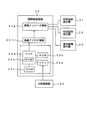
次に、パチンコ機1の主な電気的構成についてそれをブロックで示す図3を参照して説明する。
パチンコ機1には、主制御基板100が設けられており、その主制御基板100には、マイクロプロセッサ110が搭載されている。マイクロプロセッサ110は、メインCPU112と、ROM114と、RAM116とを備える。メインCPU112は、後述する第1種始動口処理、特別図柄処理、入賞の発生の検出など、遊技の進行に必要な主な制御および処理を実行する。ROM114には、メインCPU112が各種制御などを実行するための各種制御プログラム、制御プログラム実行時に参照する各種テーブルなどが記録されている。RAM116は、後述する記憶領域グループA,Bと、メインCPU112の処理結果などの遊技中に発生する各種データおよびROM114から読出された制御プログラムなどを一時的に格納する記憶領域と、電源遮断時に停電直前の遊技状態を示すデータなどをバックアップして記憶するバックアップ領域とを備える。
[Electric configuration of pachinko machine 1]
Next, the main electrical configuration of the
The
主制御基板100には、次に記載するものが電気的に接続されている。遊技球が第1種始動口21に入賞したことを検出する第1種始動口スイッチ(SW)21a、遊技球が第1種始動口22に入賞したことを検出する第1種始動口スイッチ(SW)22a、特別図柄表示器31,32を制御する図柄制御基板33、遊技中に発生する効果音を制御する音声制御基板79、保留数表示LED34などのLEDやランプ類などの発光部材の点灯・点滅を制御するランプ制御基板300、電源基板71、賞球および貸球の払出しなどを制御する払出制御基板200、大当りの発生や賞球払出数などに関する遊技盤情報をパチンコホールの管理室などに設けられたホールコンピュータへ送信するための遊技枠情報端子基板52、盤面中継基板51、遊技枠中継基板53である。
The following is electrically connected to the main control board 100. A first type start port switch (SW) 21a for detecting that a game ball has won the first
払出制御基板200には、主制御基板100から送信されてくる賞球コマンド、プリペイドカードユニット90からCR接続基板56を介して送信されてくる貸球要求信号などを受信するマイクロプロセッサ210が搭載されており、マイクロプロセッサ210には、賞球および貸球の払出しなどの制御を実行するサブCPU212と、このサブCPU212が賞球および貸球の払出しなどの制御を実行するための各種制御プログラムが記録されたROM214と、払出すべき賞球または貸球の総数やサブCPU212が各種制御プログラムを実行する際にROM214から読出された制御プログラムなどを一時的に格納するRAM216とが搭載されている。また、RAM216は、電源遮断時に、入賞数や未払いの賞球総数などを示すデータをバックアップして記憶するバックアップ領域を備える。
また、払出制御基板200には、電源基板71、発射モータ15eを駆動するための発射モータ駆動基板15c、遊技枠情報端子基板52および払出中継基板55が電気的に接続されている。発射モータ駆動基板15cには、発射モータ駆動基板15cから発射モータ15eへ駆動信号を出力させるための発射スイッチ(SW)15dが電気的に接続されている。
The payout control board 200 is equipped with a
The payout control board 200 is electrically connected to a
遊技枠中継基板53には、下受け皿7が遊技球で満杯になったことを検出する下皿満杯検出スイッチ(SW)72、球切れを検出する球切れ検出スイッチ(SW)73およびセンサ中継基板54が電気的に接続されている。センサ中継基板54は、払出装置62に備えられた前部払出センサ(SW)62a、後部払出センサ(SW)62bおよび払出中継基板55と電気的に接続されている。払出中継基板55には、払出モータ62cが電気的に接続されている。
盤面中継基板51には、大入賞口に入賞した遊技球を検出する大入賞口スイッチ(SW)41a、右入賞口(図示せず)に入賞した遊技球を検出する右入賞口スイッチ(SW)24a、左入賞口(図示せず)に入賞した遊技球を検出する左入賞口スイッチ(SW)23a、右下入賞口(図示せず)に入賞した遊技球を検出する右下入賞口スイッチ(SW)14a、左下入賞口(図示せず)に入賞した遊技球を検出する左下入賞口スイッチ(SW)44aおよび大入賞口中継基板50が電気的に接続されている。
The game frame relay board 53 includes a lower dish full detection switch (SW) 72 for detecting that the
The board relay board 51 has a big prize opening switch (SW) 41a for detecting a game ball won in the big prize opening, and a right prize opening switch (SW) for detecting a game ball won in the right prize opening (not shown). 24a, a left winning port switch (SW) 23a for detecting a game ball won in a left winning port (not shown), a lower right winning port switch (for detecting a game ball won in a lower right winning port (not shown)) SW) 14a, a lower left winning port switch (SW) 44a for detecting a game ball won in a lower left winning port (not shown) and a big winning
大入賞口中継基板50には、大入賞口内の特定領域(図示せず)を通過した遊技球を検出する特定領域スイッチ(SW)42aと、遊技球を特定領域へ案内する状態と案内しない状態とに変化する部材を動作させる特定領域ソレノイド(SL)42bと、大入賞口開閉部材41を開閉動作させる大入賞口ソレノイド(SL)41bとが電気的に接続されている。電源基板71は、CR接続基板56と電気的に接続されており、CR接続基板56には、度数表示部84に残り度数を表示するための回路が搭載された度数表示基板57と、プリペイドカードユニット90とが電気的に接続されている。度数表示基板57には、貸出ボタン81と、貸出ボタンランプ83とが電気的に接続されている。
電源基板71は、AC24V(50Hz/60Hz)の主電源70から電源の供給を受け、各基板および装置へ動作電源を供給する。図示しないが、電源基板71には、パチンコ機1の電源のON・OFFを行う電源スイッチ(SW)と、RAM116,216のバックアップ領域に記憶されているデータをクリアするためのRAMクリアスイッチとが設けられている。
The special winning
The
[図柄制御基板33の電気的構成]
次に、図柄制御基板33の主な電気的構成について、それをブロックで示す図4を参照して説明する。
図柄制御基板33にはキャラクタROM33cが搭載されており、そのキャラクタROM33cには、特別図柄、大当り図柄、ハズレ図柄、演出画像、大当り遊技中に表示する画像などを特別図柄表示器31,32に表示するための画像データが記録されている。
図柄制御基板33に搭載されたサブCPU33aは、主制御基板100のメインCPU112から送信されてきた変動開始コマンドおよび変動停止コマンドなどの画像制御コマンドを受信するとともに、その受信したコマンドの内容をROM33bに記録されたコンピュータプログラムに従って解析する。続いてサブCPU33aは、その解析結果をVDP(ビデオ・ディスプレイ・プロセッサ)33dへ送出し、VDP33dは、キャラクタROM33cから上記解析結果に対応した画像データを読出す。
[Electrical Configuration of Symbol Control Board 33]
Next, the main electrical configuration of the
A
The sub CPU 33a mounted on the
VDP33dは、キャラクタROM33cから読出した画像データを構成するドットの表示領域におけるアドレス、表示色などを上記解析結果に基づいて演算し、その演算結果を内蔵のパレットRAM33eに一時的に格納する。続いてVDP33dは、パレットRAM33eに格納されている演算結果に基づいてRGB信号を液晶アナログ基板33fへ送出する。続いて液晶アナログ基板33fは、取込んだRGB信号の色補正および輝度調整を行い、その信号を液晶インバータ基板33gへ送出する。液晶インバータ基板33gは、バックライト電源の役割を果たし、取込んだ信号を昇圧(たとえば、12Vから600V)し、特別図柄表示器31,32および演出画像表示器30へ送出する。そして特別図柄表示器31,32および演出画像表示器30は、取込んだ信号に対応する液晶ドットをスイッチングして表示する。これにより、各種の画像が表示される。
なお、この実施形態では、特別図柄表示器31,32および演出画像表示器30は、それぞれTFT(Thin Film Transistor)を画素駆動素子とするアクティブマトリックス方式の液晶表示装置である。
The
In this embodiment, the special symbol displays 31 and 32 and the
[記憶領域]
次に、遊技球が第1種始動口21,22に入賞したときに発生するデータを記憶するための記憶領域ついて図5および図6を参照して説明する。
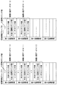
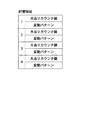
図5は記憶領域グループA、Bの説明図であり、図6は図5に示す状態から各データが移動した後の状態を示す説明図である。
RAM116には記憶領域グループAおよび記憶領域グループBが備えられている。記憶領域グループAは、遊技球が第1種始動口21に入賞したときに発生したデータを記憶し、記憶領域グループBは、遊技球が第1種始動口22に入賞したときに発生したデータを記憶する。記憶領域グループA、Bは、それぞれ第1記憶領域ないし第4記憶領域の4つの記憶領域を備える。遊技球が第1種始動口21または22に入賞すると、入賞順カウンタ値、大当りカウンタ値、大当り図柄カウンタ値およびリーチカウンタ値の計4種類のデータが発生し、それら4種類のデータが記憶領域に記憶される。
[Storage area]
Next, a storage area for storing data generated when a game ball wins the first
FIG. 5 is an explanatory diagram of the storage area groups A and B, and FIG. 6 is an explanatory diagram showing a state after each data is moved from the state shown in FIG.
The RAM 116 includes a storage area group A and a storage area group B. The storage area group A stores data generated when the game ball wins the first
入賞順カウンタ値は、遊技球が第1種始動口21,22に入賞した順番をカウントする入賞順カウンタのカウンタ値であり、遊技球が第1種始動口21または22に入賞する毎に「1」ずつカウントアップする。たとえば、入賞順カウンタがのカウンタ値が「9」のときに遊技球が第1種始動口21または22に入賞すると、カウンタ値は「10」となり、その「10」が入賞順カウンタ値として記憶領域に記憶される。
大当りカウンタ値は、大当り判定に用いるカウンタ値をカウントする大当りカウンタのカウンタ値であり、大当りカウンタは、複数のカウンタ値、この実施形態では0〜952の計953個の大当りカウンタ値をカウントする。たとえば、遊技球が第1種始動口21または22に入賞したときに大当りカウンタが「7」をカウントしていたときは、そのカウンタ値「7」が大当りカウンタ値として記憶領域に記憶される。
The winning order counter value is a counter value of a winning order counter that counts the order in which the game balls have won the first type start
The jackpot counter value is a counter value of a jackpot counter that counts a counter value used for jackpot determination. The jackpot counter counts a plurality of counter values, that is, a total of 953 jackpot counter values of 0 to 952 in this embodiment. For example, when the big hit counter is counting “7” when the game ball wins the first
大当り図柄カウンタ値は、大当り図柄を決定するために用いるカウンタ値をカウントする大当り図柄カウンタのカウンタ値であり、大当り図柄カウンタは、複数のカウンタ値、この実施形態では0〜99の計100個のカウンタ値をカウントする。たとえば、大当り図柄を決定するタイミングになったときに大当り図柄カウンタが「7」をカウントしていたときは、そのカウンタ値「7」が大当り図柄カウンタ値として記憶領域に記憶される。
リーチカウンタ値は、特別図柄の変動パターンとしてリーチパターンを決定するか否かの判定を行うために用いるカウンタ値をカウントするリーチカウンタのカウンタ値であり、リーチカウンタは、複数の数値、この実施形態では、0〜49の計50個のカウンタ値をカウントする。たとえば、リーチパターンを決定するか否かを判定するタイミングになったときにリーチカウンタが「17」をカウントしていたときは、そのカウンタ値「17」がリーチカウンタ値として記憶領域に記憶される。なお、リーチとは、大当り図柄になる一歩手前の状態をいい、リーチパターンとは、リーチ特有の演出画像を表示する変動パターンをいう。この実施形態では、大当り図柄を「7」、「77」であるとすると、特別図柄表示器31,32が特別図柄「6」または「76」を表示している状態をリーチといい、特別図柄「6」または「76」が表示されたとき、あるいは、それよりも数図柄前のときから特別図柄の変動速度(移動速度)を低下させ、大当り図柄を通過したり、戻ったりするなど、大当り図柄で停止するかどうか、遊技者をハラハラドキドキさせる演出を行う変動パターンをリーチパターンという。
The jackpot symbol counter value is a counter value of the jackpot symbol counter that counts the counter value used to determine the jackpot symbol. The jackpot symbol counter has a plurality of counter values, in this embodiment, a total of 100 counter values of 0 to 99. Count the counter value. For example, if the big hit symbol counter is counting “7” when it is time to determine the big hit symbol, the counter value “7” is stored in the storage area as the big hit symbol counter value.
The reach counter value is a counter value of a reach counter that counts a counter value used to determine whether or not to determine a reach pattern as a special symbol variation pattern. Then, a total of 50 counter values from 0 to 49 are counted. For example, when the reach counter is counting “17” when it is time to determine whether or not to determine the reach pattern, the counter value “17” is stored in the storage area as the reach counter value. . Reach refers to a state one step before the big hit symbol, and reach pattern refers to a variation pattern that displays a reach-specific effect image. In this embodiment, when the jackpot symbol is “7” or “77”, the
以下、入賞順カウンタ値、大当りカウンタ値、大当り図柄カウンタ値およびリーチカウンタ値を始動入賞データといい、記憶領域グループAに記憶されている始動入賞データには符号Aを付し、記憶領域グループBに記憶されている始動入賞データには符号Bを付す。また、入賞順カウンタ値を符号AまたはBの後に付す。
図5に示す例では、記憶領域グループAの第1記憶領域から第3記憶領域に始動入賞データA10,A11,A13が記憶されており、記憶領域グループBの第1記憶領域および第2記憶領域に始動入賞データB12,B14が記憶されている。記憶領域グループA、Bに記憶されている始動入賞データは、入賞順カウンタ値の小さい順に読出され、その読出された各カウンタ値に基づいて大当り判定および特別図柄表示器31,32の制御が行われる。図5に示す例では、記憶領域グループAの第1記憶領域に記憶されている始動入賞データA10が最も小さいため、始動入賞データA10が最初に読出され、以下、特別図柄の変動表示が終了する毎に、始動入賞データA11、B12、A13、B14の順に読出される。
また、特別図柄の変動表示が1回終了する毎に、その変動表示に用いられた始動入賞データが記憶されていた記憶領域の他の始動入賞データが、自身の記憶領域の記憶順位よりも記憶順位が1つ若い記憶領域へそれぞれ移動する。図6に示す例では、記憶領域グループAに記憶されていた始動入賞データA10が読出されたため、記憶領域グループAの第2記憶領域に記憶されていた始動入賞データA11が第1記憶領域へ移動し、第3記憶領域に記憶されていた始動入賞データA13が第2記憶領域へ移動している。
Hereinafter, the winning order counter value, the jackpot counter value, the jackpot symbol counter value, and the reach counter value are referred to as starting winning data. The starting winning data stored in the storage area group A is denoted by the symbol A, and the storage area group B. The start winning data stored in is attached with a symbol B. The winning order counter value is added after the symbol A or B.
In the example shown in FIG. 5, start winning data A10, A11, A13 are stored in the third storage area from the first storage area of the storage area group A, and the first storage area and the second storage area of the storage area group B are stored. The start winning data B12 and B14 are stored. The start winning data stored in the storage area groups A and B are read in ascending order of the winning order counter values, and the jackpot determination and the control of the
In addition, every time the variation display of the special symbol is finished once, the other start winning data in the storage area in which the start winning data used for the variation display is stored is stored more than the storage order of the own storage area. Each storage area moves to the next lower rank. In the example shown in FIG. 6, since the start winning data A10 stored in the storage area group A is read, the starting winning data A11 stored in the second storage area of the storage area group A is moved to the first storage area. Then, the start winning data A13 stored in the third storage area is moved to the second storage area.
[遊技の主な流れ]
次に、遊技の主な流れについて図7ないし図10を参照して説明する。
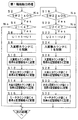
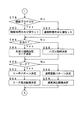
図7はメインCPU112が実行する第1種始動口処理の流れを示すフローチャートである。図8はメインCPU112が実行する特別図柄処理の流れを示すフローチャートであり、図9は図8の処理の続きを示すフローチャートであり、図10は図9の処理の続きを示すフローチャートである。
(第1種始動口処理)
メインCPU112は、第1種始動口スイッチ(SW)21aがONしたか否か、つまり遊技球が第1種始動口21に入賞したか否かの出力判定を行い(図7のステップ(以下、Sと略す)2)、入賞したと判定すると(S2:Yes)、第1種始動口21に対する保留数U1が上限の4個未満であるか否かを判定する(S4)。ここで、4個未満であると判定すると(S4:Yes)、保留数U1に「1」を加算する(S6)。続いてメインCPU112は、入賞順カウンタに「1」を加算し(S8)、その加算後の入賞順カウンタのカウンタ値を入賞順カウンタ値C1として記憶領域グループAの空き領域のうち、最も小さい順位の記憶領域に記憶する(S10)。続いてメインCPU112は、このとき大当りカウンタがカウントしたカウンタ値を取得し、それを大当りカウンタ値C2として、S10にて入賞順カウンタ値C1が記憶された記憶領域に記憶する(S12)。続いてメインCPU112は、このとき大当り図柄カウンタがカウントしたカウンタ値を取得し、それを大当り図柄カウンタ値C3として、S12にて大当りカウンタ値C2が記憶された記憶領域に記憶する(S14)。続いてメインCPU112は、このときリーチカウンタがカウントしてカウンタ値を取得し、それをリーチカウンタ値C4として、S14にて大当り図柄カウンタ値C3が記憶された記憶領域に記憶する(S16)。
[Main game flow]
Next, the main flow of the game will be described with reference to FIGS.
FIG. 7 is a flowchart showing the flow of the first type start port process executed by the main CPU 112. FIG. 8 is a flowchart showing the flow of special symbol processing executed by the main CPU 112, FIG. 9 is a flowchart showing the continuation of the processing of FIG. 8, and FIG. 10 is a flowchart showing the continuation of the processing of FIG.
(
The main CPU 112 determines whether or not the first type start port switch (SW) 21a is turned on, that is, whether or not the game ball has won the first type start port 21 (steps in FIG. 2) If it is determined that a prize has been won (S2: Yes), it is determined whether or not the number of holdings U1 for the first
また、メインCPU112は、遊技球が第1種始動口21に入賞していないと判定した場合は(S2:No)、第1種始動口スイッチ(SW)22aがONしたか否か、つまり、遊技球が第1種始動口22に入賞したか否かの判定を行い(S18)、入賞したと判定すると(S18:Yes)、第1種始動口22に対する保留数U2が上限の4個未満であるか否かを判定する(S20)。ここで、4個未満であると判定すると(S20:Yes)、保留数U2に「1」を加算する(S22)。続いてメインCPU112は、入賞順カウンタに「1」を加算し(S24)、その加算後の入賞順カウンタのカウンタ値を入賞順カウンタ値C1として記憶領域グループBの空き領域のうち、最も小さい順位の記憶領域に記憶する(S26)。続いてメインCPU112は、このとき大当りカウンタがカウントしたカウンタ値を取得し、それを大当りカウンタ値C2として、S26にて入賞順カウンタ値C1が記憶された記憶領域に記憶する(S28)。続いてメインCPU112は、このとき大当り図柄カウンタがカウントしたカウンタ値を取得し、それを大当り図柄カウンタ値C3として、S28にて大当りカウンタ値C2が記憶された記憶領域に記憶する(S30)。続いてメインCPU112は、このときリーチカウンタがカウントしてカウンタ値を取得し、それをリーチカウンタ値C4として、S30にて大当り図柄カウンタ値C3が記憶された記憶領域に記憶する(S32)。
以上のようにメインCPU112は、遊技球が第1種始動口21に入賞したときは始動入賞データを記憶領域グループAに記憶し、第1種始動口22に入賞したときは始動入賞データを記憶領域グループBに記憶する。つまり、遊技球が第1種始動口21および22のどちらに入賞したかに応じて始動入賞データを記憶領域グループA、Bに振り分けて記憶する。
When the main CPU 112 determines that the game ball has not won the first type starting port 21 (S2: No), whether or not the first type starting port switch (SW) 22a is turned on, that is, It is determined whether or not the game ball has won the first type starting port 22 (S18), and if it is determined that the winning ball has been won (S18: Yes), the number of holds U2 for the first
As described above, the main CPU 112 stores the start winning data in the storage area group A when the game ball wins the first
(特別図柄処理)
メインCPU112は、特別図柄表示器31および32のいずれかが特別図柄を変動中であるか否かを判定し(図8のS50)、変動中ではないと判定した場合は(S50:No)、保留数U1が1以上であるか否かを判定する(S52)。ここで1以上であると判定した場合は(S52:Yes)、保留数U2が1以上であるか否かを判定し(S54)、1以上であると判定した場合は(S54:Yes)、記憶領域グループA、Bの各第1記憶領域に記憶されている入賞順カウンタ値をそれぞれ読出す(S56)。続いてメインCPU112は、S56にて読出した記憶領域グループAの第1記憶領域から読出した入賞順カウンタ値Aが、記憶領域グループBの第1記憶領域から読出した入賞順カウンタ値Bよりも小さいか否かを判定する(S58)。
つまり、入賞順カウンタ値Aの方が入賞順カウンタ値Bよりも前に記憶されたか否かを判定する。ここで、入賞順カウンタ値Aの方が入賞順カウンタ値Bよりも前に記憶されたと判定した場合は(S58:Yes)、保留数U1から「1」を減算し(S60)、記憶領域グループAの第1記憶領域に記憶されている始動入賞データを読出して所定の記憶領域に一時記憶する(S62)。続いてメインCPU112は、その一時記憶した始動入賞データが記憶領域グループAから読出したものであることを示すフラグAをONし(S64)、記憶領域グループAの他の記憶領域に記憶されている始動入賞データを、自身の記憶順位よりも1つ小さい記憶順位の記憶領域へそれぞれ移動させる(S66)。
(Special symbol processing)
The main CPU 112 determines whether any of the
That is, it is determined whether or not the winning order counter value A is stored before the winning order counter value B. If it is determined that the winning order counter value A is stored before the winning order counter value B (S58: Yes), “1” is subtracted from the holding number U1 (S60), and the storage area group The start winning data stored in the first storage area A is read and temporarily stored in a predetermined storage area (S62). Subsequently, the main CPU 112 turns on the flag A indicating that the temporarily stored start winning data is read from the storage area group A (S64), and is stored in another storage area of the storage area group A. The start winning data is moved to a storage area having a storage order that is one smaller than its own storage order (S66).
またメインCPU112は、入賞順カウンタ値Aの方が入賞順カウンタ値Bよりも前に記憶されていない、つまり入賞順カウンタ値Bの方が入賞順カウンタ値Aよりも前に記憶されたと判定した場合は(S58:No)、保留数U2から「1」を減算し(S68)、記憶領域グループBの第1記憶領域に記憶されている始動入賞データを読出して所定の記憶領域に一時記憶する(S70)。続いてメインCPU112は、その一時記憶した始動入賞データが記憶領域グループBから読出したものであることを示すフラグBをONし(S72)、記憶領域グループBの他の記憶領域に記憶されている始動入賞データを、自身の記憶順位よりも1つ小さい記憶順位の記憶領域へそれぞれ移動させる(S74)。 Further, the main CPU 112 determines that the winning order counter value A is not stored before the winning order counter value B, that is, the winning order counter value B is stored before the winning order counter value A. In this case (S58: No), “1” is subtracted from the holding number U2 (S68), and the start winning data stored in the first storage area of the storage area group B is read and temporarily stored in a predetermined storage area. (S70). Subsequently, the main CPU 112 turns on the flag B indicating that the temporarily stored start winning data is read from the storage area group B (S72) and is stored in another storage area of the storage area group B. The start winning data is moved to a storage area having a storage order that is one lower than its own storage order (S74).
またメインCPU112は、保留数U1は「1」以上あるが(S52:Yes)、保留数U2が存在しないと判定した場合は(S54:No)、記憶領域グループAの第1記憶領域に記憶されている始動入賞データを読出して一時記憶し(S62)、フラグAをONし(S64)、記憶領域グループAのデータ移動を行う(S66)。またメインCPU112は、保留数U1は存在しないが(S52:No)、保留数U2が「1」以上あると判定した場合は(S76:No)、記憶領域グループBの第1記憶領域に記憶されている始動入賞データを読出して一時記憶し(S70)、フラグBをONし(S72)、記憶領域グループBのデータ移動を行う(S74)。 If the main CPU 112 determines that the number of holds U1 is “1” or more (S52: Yes) but the number of holds U2 does not exist (S54: No), it is stored in the first storage area of the storage area group A. The start winning data is read and temporarily stored (S62), the flag A is turned on (S64), and the data of the storage area group A is moved (S66). Further, when the main CPU 112 determines that the hold number U1 does not exist (S52: No) but the hold number U2 is “1” or more (S76: No), the main CPU 112 stores the hold number U1 in the first storage area of the storage area group B. The start winning data is read and temporarily stored (S70), the flag B is turned ON (S72), and the data of the storage area group B is moved (S74).
そしてメインCPU112は、確変フラグがONしているか否かを判定する(図9のS78)。ここで確変とは、高確率および通常確率の2種類の大当りの発生確率のうち、高確率に設定されている遊技状態のことをいい、確変フラグとは、遊技状態が確変に変化していることを示すフラグをいう。ここで、確変フラグがONしていると判定した場合は(S78:Yes)、確変時用大当り値をセットし(S80)、ONしていないと判定した場合は(S78:No)、通常時用大当り値をセットする(S82)。ここで、大当り値とは、大当りカウンタのカウンタ値のうち、メインCPU112が大当たりと判定するカウンタ値をいい、確変時用大当り値とは、確変時の大当り判定において用いる大当り値であり、通常時用大当り値とは、通常時の大当り判定において用いる大当り値である。たとえば、通常時用大当り値は、「7」「277」「293」の計3個であり、確変時用大当り値は、「7」「53」「89」「137」「173」「197」「257」「277」「293」「307」「337」「359」「409」「457」「487」「523」の計16個の大当り値である。つまり、確変時の大当り発生確率は、通常時よりも約5倍(=16/3)に高くなっている。 Then, the main CPU 112 determines whether or not the probability variation flag is ON (S78 in FIG. 9). Here, the probability change means a gaming state that is set to a high probability among the two types of jackpot occurrence probabilities, a high probability and a normal probability, and the probability variation flag indicates that the gaming state has changed to a certain probability. A flag indicating that. Here, when it is determined that the probability variation flag is ON (S78: Yes), a jackpot value for probability variation is set (S80), and when it is determined that the probability variation flag is not ON (S78: No), normal time A big jackpot value is set (S82). Here, the jackpot value is a counter value determined by the main CPU 112 as a jackpot value out of the counter value of the jackpot counter. The jackpot value for probability change is a jackpot value used in the jackpot determination at the time of probability change. The jackpot value is a jackpot value used in the jackpot determination in normal times. For example, the normal-time big hit values are “7”, “277”, and “293” in total, and the positive-change big hit values are “7”, “53”, “89”, “137”, “173”, and “197”. “257”, “277”, “293”, “307”, “337”, “359”, “409”, “457”, “487”, and “523”, a total of 16 jackpot values. That is, the probability of occurrence of a big hit at the time of probability change is about five times (= 16/3) higher than the normal time.
続いてメインCPU112は、先のS62またはS70にて一時記憶した始動入賞データに含まれる大当りカウンタ値を読出し、それと同じ数値の大当り値がS80またはS82にてセットした大当り値の中に存在するか否か検索し、存在する場合は大当りと判定し(S84:Yes)、存在しない場合はハズレと判定する(S84:No)。ここで大当りと判定した場合は(S84:Yes)、先のS62またはS70にて一時記憶した始動入賞データに含まれる大当り図柄カウンタ値を読出し、大当り図柄を決定する(S86)。この大当り図柄の決定は、大当り図柄カウンタ値と大当り図柄とを対応付けて構成される大当り図柄テーブルを用いて行い、その大当り図柄テーブルから大当り図柄カウンタ値に対応する大当り図柄を選択する。たとえば、大当り図柄テーブルが、大当り図柄カウンタ値0〜2と、大当り図柄「7」、「55」および「77」とを対応付けて構成されている場合に大当り図柄カウンタ値が「2」であった場合は、その「2」に対応する大当り図柄「77」を大当り図柄テーブルから選択する。 Subsequently, the main CPU 112 reads the jackpot counter value included in the start winning data temporarily stored in the previous S62 or S70, and whether the same big jackpot value exists in the jackpot value set in S80 or S82. If it exists, it is determined that it is a big hit (S84: Yes), and if it does not exist, it is determined that it is lost (S84: No). When it is determined that the game is a big hit (S84: Yes), the big hit symbol counter value included in the start winning data temporarily stored in the previous S62 or S70 is read and the big hit symbol is determined (S86). The determination of the jackpot symbol is performed using a jackpot symbol table configured by associating the jackpot symbol counter value with the jackpot symbol, and the jackpot symbol corresponding to the jackpot symbol counter value is selected from the jackpot symbol table. For example, when the jackpot symbol table is configured by associating the jackpot symbol counter values 0 to 2 with the jackpot symbols “7”, “55”, and “77”, the jackpot symbol counter value is “2”. In the case, the jackpot symbol “77” corresponding to “2” is selected from the jackpot symbol table.
また、この実施形態では、大当り図柄を表示する場合は、特別図柄の変動パターンとして必ずリーチパターンを実行するためリーチパターンの実行を決定する(S86)。またメインCPU112は、ハズレと判定した場合は(S84:No)、ハズレ図柄を決定する(S88)。このハズレ図柄の決定は、複数のハズレ図柄カウンタ値と複数のハズレ図柄とを対応付けて構成されるハズレ図柄テーブルと、ハズレ図柄カウンタとを用いて行う。たとえば、ハズレ図柄テーブルが、ハズレ図柄カウンタ値0〜99と、ハズレ図柄「0」〜「99」とを対応付けて構成されており、ハズレ図柄カウンタが0〜99のカウンタ値をカウントする場合に、ハズレ図柄カウンタから取得したカウンタ値が「6」であった場合は、その「6」に対応するハズレ図柄「6」をハズレ図柄テーブルから選択する。 Further, in this embodiment, when a big hit symbol is displayed, execution of the reach pattern is determined in order to always execute the reach pattern as the variation pattern of the special symbol (S86). When determining that the main CPU 112 has lost (S84: No), the main CPU 112 determines a lost symbol (S88). This losing symbol determination is performed using a losing symbol table configured by associating a plurality of losing symbol counter values with a plurality of losing symbols, and a losing symbol counter. For example, when the lost symbol table is configured by associating the lost symbol counter values 0 to 99 with the lost symbols “0” to “99”, and the lost symbol counter counts the counter values 0 to 99. When the counter value acquired from the lost symbol counter is “6”, the lost symbol “6” corresponding to “6” is selected from the lost symbol table.
続いてメインCPU112は、先のS62またはS70にて一時記憶した始動入賞データに含まれるリーチカウンタ値を読出し、そのリーチカウンタ値が所定のリーチカウンタ値(たとえば、「7」「17」「27」「37」のいずれか)である場合はリーチパターンを実行すると判定し(S90:Yes)、所定のリーチカウンタ値でない場合はリーチパターンを実行しないと判定する(S90:No)。ここでリーチパターンを実行すると判定した場合は(S90:Yes)、リーチパターンの種類を決定する(S92)。この決定は、複数のカウンタ値と複数種類のリーチパターンとを対応付けて構成されるリーチパターンテーブルと、複数のカウンタ値をカウントするリーチパターンカウンタとを用いて行う。たとえば、リーチパターンカウンタが0〜29の計30個のカウンタ値をカウントし、リーチパターンテーブルが0〜29のカウンタ値とリーチパターン0〜29とを対応付けて構成されている場合に、リーチパターンカウンタから取得したカウンタ値が「10」であった場合は、その「10」に対応するリーチパターン10をリーチパターンテーブルから選択する。なお、各リーチパターンには、特別図柄の変動表示を開始してから大当り図柄またはハズレ図柄が確定表示されるまでにかかる時間(以下、変動時間という)と、リーチパターンの内容とがそれぞれ対応付けられている。
Subsequently, the main CPU 112 reads the reach counter value included in the start winning data temporarily stored in S62 or S70, and the reach counter value is a predetermined reach counter value (for example, “7” “17” “27”). If it is “37”, it is determined that the reach pattern is to be executed (S90: Yes), and if it is not the predetermined reach counter value, it is determined that the reach pattern is not to be executed (S90: No). If it is determined that the reach pattern is to be executed (S90: Yes), the type of reach pattern is determined (S92). This determination is performed using a reach pattern table configured by associating a plurality of counter values with a plurality of types of reach patterns, and a reach pattern counter that counts a plurality of counter values. For example, when the reach pattern counter counts a total of 30 counter values from 0 to 29, and the reach pattern table is configured by associating the counter values from 0 to 29 with the
続いてメインCPU112は、リーチのときに演出画像表示器30に表示する画像(以下、リーチ演出画像という)の種類を決定する(S94)。この決定は、複数のカウンタ値と複数種類のリーチ演出画像とを対応付けて構成されるリーチ演出画像テーブルと、複数のカウンタ値をカウントするリーチ演出画像カウンタとを用いて行う。たとえば、リーチ演出画像カウンタが0〜9の計10個のカウンタ値をカウントし、リーチ演出画像テーブルが0〜9のカウンタ値とリーチ演出画像0〜9とを対応付けて構成されている場合に、リーチ演出画像カウンタから取得したカウンタ値が「5」であった場合は、その「5」に対応するリーチ演出画像5をリーチ演出画像テーブルから選択する。
またメインCPU112は、リーチパターンを実行しないと判定した場合は(S90:No)、通常変動パターンを決定する(S96)。この決定は、複数のカウンタ値と複数種類の通常変動パターンとを対応付けて構成される通常変動パターンテーブルと、複数のカウンタ値をカウントする通常変動パターンカウンタとを用いて行う。たとえば、通常変動パターンカウンタが0〜19の計20個のカウンタ値をカウントし、通常変動パターンテーブルが0〜19のカウンタ値と通常変動パターン0〜19とを対応付けて構成されている場合に、通常変動パターンカウンタから取得したカウンタ値が「15」であった場合は、その「15」に対応する通常変動パターン15を通常変動パターンテーブルから選択する。なお、各通常変動パターンには、変動時間と、通常変動パターンの内容とがそれぞれ対応付けられている。
Subsequently, the main CPU 112 determines the type of image (hereinafter referred to as reach effect image) to be displayed on the
When determining that the reach pattern is not to be executed (S90: No), the main CPU 112 determines the normal variation pattern (S96). This determination is performed using a normal variation pattern table configured by associating a plurality of counter values with a plurality of types of normal variation patterns, and a normal variation pattern counter that counts a plurality of counter values. For example, when the normal variation pattern counter counts a total of 20 counter values from 0 to 19, and the normal variation pattern table is configured by associating the counter values from 0 to 19 with the
続いてメインCPU112は、通常変動パターンのときに演出画像表示器30に表示する画像(以下、通常演出画像という)の種類を決定する(S98)。この決定は、複数のカウンタ値と複数種類の通常演出画像とを対応付けて構成される通常演出画像テーブルと、複数のカウンタ値をカウントする通常演出画像カウンタとを用いて行う。たとえば、通常演出画像カウンタが0〜19の計20個のカウンタ値をカウントし、通常演出画像テーブルが0〜19のカウンタ値と通常演出画像0〜19とを対応付けて構成されている場合に、通常演出画像カウンタから取得したカウンタ値が「12」であった場合は、その「12」に対応する通常演出画像12を通常演出画像テーブルから選択する。
続いてメインCPU112は、フラグAがONしているか否かを判定し(図10のS100)、ONしていると判定した場合は(S100:Yes)、変動開始コマンドAを図柄制御基板33へ送信し(S102)、その変動開始コマンドAに含まれているリーチパターンまたは通常変動パターンの変動時間の計測を開始する(S104)。
Subsequently, the main CPU 112 determines the type of image (hereinafter referred to as a normal effect image) to be displayed on the
Subsequently, the main CPU 112 determines whether or not the flag A is ON (S100 in FIG. 10). If it is determined that the flag A is ON (S100: Yes), the fluctuation start command A is sent to the
また、フラグAがONしていないと判定した場合は(S100:No)、変動開始コマンドBを図柄制御基板33へ送信し(S112)、その変動開始コマンドBに含まれているリーチパターンまたは通常変動パターンの変動時間の計測を開始する(S114)。
変動開始コマンドAは、特別図柄表示器31に特別図柄の変動表示を開始させるためのコマンドであり、変動開始コマンドBは、特別図柄表示器32に特別図柄の変動表示を開始させるためのコマンドである。各変動開始コマンドには、先のS86〜S98にて決定した内容を示すデータが含まれる。
一方、変動開始コマンドAを受信した図柄制御基板33は、サブCPU33aが変動開始コマンドAを解析し、その解析結果に基づいて特別図柄表示器31に特別図柄の変動表示を実行させ、演出画像表示器30に所定の演出画像を表示させる。また、変動開始コマンドBを受信した場合は、その変動開始コマンドBの解析結果に基づいて特別図柄表示器32に特別図柄の変動表示を実行させ、演出画像表示器30に所定の演出画像を表示させる。
If it is determined that the flag A is not ON (S100: No), the variation start command B is transmitted to the symbol control board 33 (S112), and the reach pattern included in the variation start command B or normal Measurement of the variation time of the variation pattern is started (S114).
The change start command A is a command for starting the special symbol display on the
On the other hand, in the
そしてメインCPU112は、先のS104にて計測を開始した変動時間がタイムアップすると、特別図柄表示器31による特別図柄の変動表示を終了するタイミングになったと判定し(S106:Yes)、特別図柄表示器31の変動停止を指示する変動停止コマンドAを図柄制御基板33へ送信し(S108)、フラグAをOFFする(S110)。また、先のS114にて計測を開始した変動時間がタイムアップすると、特別図柄表示器32による特別図柄の変動表示を終了するタイミングになったと判定し(S116:Yes)、特別図柄表示器32の変動停止を指示する変動停止コマンドBを図柄制御基板33へ送信し(S118)、フラグAをOFFする(S120)。
一方、変動停止コマンドAを受信した図柄制御基板33のサブCPU33aは、特別図柄表示器31の変動表示を停止させ、先のS86にて決定した大当り図柄、またはS88にて決定したハズレ図柄を特別図柄表示器31に確定表示させる。また、変動停止コマンドBを受信した図柄制御基板33のサブCPU33aは、特別図柄表示器32の変動表示を停止させ、先のS86にて決定した大当り図柄、またはS88にて決定したハズレ図柄を特別図柄表示器32に確定表示させる。
Then, the main CPU 112 determines that it is time to end the variation display of the special symbol by the
On the other hand, the sub CPU 33a of the
以上のように、メインCPU112は、記憶領域グループAから読出した始動入賞データに基づいて特別図柄表示器31に特別図柄の変動表示を行わせる場合は変動開始コマンドAを図柄制御基板33へ送信し、その変動表示を停止させる場合は変動停止コマンドAを図柄制御基板33へ送信する。また、記憶領域グループBから読出した始動入賞データに基づいて特別図柄表示器32に特別図柄の変動表示を行わせる場合は変動開始コマンドBを図柄制御基板33へ送信し、その変動表示を停止させる場合は変動停止コマンドBを図柄制御基板33へ送信する。
つまり、メインCPU112は、記憶領域グループA、Bのどちらから読出した始動入賞データであるかを識別可能なコマンドを図柄制御基板33へ送信するため、図柄制御基板33は、受信したコマンドが特別図柄表示器31,32のどちらを制御するためのコマンドであるかを正確に判定することができる。
As described above, the main CPU 112 transmits the variation start command A to the
That is, since the main CPU 112 transmits a command that can identify which start winning data is read from the storage area group A or B to the
[最良の形態の効果]
(1)以上のように上記最良の形態のパチンコ機1を使用すれば、メインCPU112は、第1種始動口スイッチ21a,22aから出力された検出信号が、どちらの第1種始動口スイッチから出力されたかの出力判定を行い、始動入賞データを、入賞順カウンタ値に従うとともに出力判定の結果を示す識別符号A、Bと対応付けて記憶領域グループA、Bに振り分けることができるため、各始動入賞データに対応付けられている符号A、Bを解析すれば、第1種始動口21,22のどちらに入賞したときに記憶された始動入賞データであるか判定することができる。
従って、メインCPU112が識別符号A、Bが付された変動開始コマンドおよび変動停止コマンドを図柄制御基板33へ送信することにより、図柄制御基板33は受信したコマンドが特別図柄表示器31,32のどちらを制御するためのコマンドであるかを判定することができる。このため、受信したコマンドに対応する特別図柄表示器を制御することができる。
(2)しかも、特別図柄の変動表示に用いられた始動入賞データが記憶されていた記憶領域グループの中でのみ始動入賞データの移動を行うことができるため、その移動を行うメインCPU112の処理量を減少させることができる。
[Effect of the best form]
(1) As described above, if the
Therefore, when the main CPU 112 transmits the fluctuation start command and the fluctuation stop command with the identification codes A and B to the
(2) Moreover, since the start winning data can be moved only within the storage area group in which the starting winning data used for the special symbol variation display is stored, the processing amount of the main CPU 112 that performs the movement Can be reduced.
[その他の実施形態]
(1)前記最良の形態では、特別図柄表示器を2つ備えたパチンコ機を説明したが、1つ、または3つ以上設けてもよい。特別図柄表示器を3つ以上設けた場合は、その数と同じ数の第1種始動口を設け、記憶領域グループも同数増設し、各記憶領域と各第1種始動口とを対応付ける。このように特別図柄表示器を3つ以上設けた場合も前記最良の形態による効果(1)および(2)と同じ効果を奏することができる。
(2)記憶領域グループに記憶されている始動入賞データの移動は、一度に行うのではなく、パチンコ機1のマシンサイクル(たとえば2ms)毎に始動入賞データを1つだけ移動させることもできる。これによれば、データ移動のためのメインCPU112の処理量をさらに軽減することができる。
(3)前記各実施形態において記載した数値およびデータの種類などは一例であり、他の数値およびデータに変更できることは勿論である。
[Other Embodiments]
(1) In the best mode, a pachinko machine equipped with two special symbol displays has been described, but one or three or more may be provided. When three or more special symbol indicators are provided, the same number of first type start ports are provided, the same number of storage area groups are added, and each storage area is associated with each first type start port. Thus, even when three or more special symbol indicators are provided, the same effects as the effects (1) and (2) of the best mode can be obtained.
(2) The start winning data stored in the storage area group is not moved at a time, but only one start winning data can be moved every machine cycle (for example, 2 ms) of the
(3) The numerical values and data types described in the above embodiments are merely examples, and of course, other numerical values and data can be changed.
[請求項1と実施形態との対応関係]
第1種始動口21,22が所定の領域に対応し、第1種始動口スイッチ21a,22aが検出手段に対応する。大当りカウンタがカウンタに対応し、特別図柄表示器31,32が表示装置に対応する。入賞順カウンタ値が順番情報に対応し、始動入賞データがグループ情報に対応する。
そしてメインCPU112が実行する特別図柄処理のS78〜S84(図9)が判定手段として機能し、第1種始動口処理(図7のS2〜S32)が振分手段として機能し、特別図柄処理のS66,S74(図8)が移動手段として機能する。
[Correspondence between
The first type start
The special symbol processing S78 to S84 (FIG. 9) executed by the main CPU 112 functions as a determination unit, and the first type start port processing (S2 to S32 in FIG. 7) functions as a distribution unit. S66 and S74 (FIG. 8) function as moving means.
1 パチンコ機
21,22 第1種始動口(所定の領域)
21a,22a 第1種始動口スイッチ(検出手段)
30 演出画像表示器
31,32 特別図柄表示器(表示装置)
A10 始動入賞データ(グループ情報)
1
21a,
30
A10 Start winning data (group information)
Claims (1)
前記検出信号が出力されたときにカウンタからカウンタ値を取得し、その取得したカウンタ値が大当りに相当するカウンタ値であるか否かにより大当りかハズレかを判定する判定手段と、
前記遊技球が前記所定の領域を通過した場合に、相互に識別可能な複数種類の識別情報を変動表示した後に前記判定手段の判定結果に対応する識別情報を確定表示するとともに、前記変動表示を行っている途中で前記遊技球が前記所定の領域を通過した場合は、その通過による前記変動表示を保留する表示装置とを備えており、
前記表示装置は、前記識別情報の変動開始から確定表示までを1回の変動表示とした場合に、前記変動表示を行っている場合は、その変動表示が終了した後に、前記保留を行った数と同じ回数分の変動表示を行うことが可能なパチンコ機において、
前記所定の領域が前記遊技領域に複数設けられており、
前記検出手段が前記所定の領域毎に設けられており、
前記保留が発生した順番を示す順番情報と、前記保留が発生したときに前記カウンタから取得したカウンタ値とを含むグループ情報をグループ単位で記憶可能な記憶領域を前記所定の領域と対応付けて複数ずつ有する複数の記憶領域グループと、
前記検出手段から出力された検出信号が、どの検出手段から出力されたかの出力判定を行い、前記グループ情報を、前記順番に従うとともに前記出力判定の結果と対応付けて各記憶領域グループに振り分ける振分手段と、
前記表示装置が、いずれかの記憶領域グループに記憶されている前記グループ情報を用いて前記変動表示を行った場合に、その用いられたグループ情報が記憶されていた記憶領域グループの中において前記用いられたグループ情報の順番の次の順番で記憶されていた他のグループ情報を、前記用いられたグループ情報が記憶されていた記憶領域に移動する移動手段と、
を備えたことを特徴とするパチンコ機。
Detecting means for detecting that the game ball launched by the game ball launching device for launching the game ball has passed a predetermined area provided in the game area on the game board surface and outputting a detection signal;
A determination means for acquiring a counter value from a counter when the detection signal is output, and determining whether the acquired counter value is a counter value corresponding to a big hit or not based on whether or not the big hit or lost;
When the game ball passes through the predetermined area, a plurality of types of identification information that can be distinguished from each other are variably displayed, and then identification information corresponding to the determination result of the determination means is fixedly displayed, and the variation display is displayed. When the game ball passes the predetermined area in the middle of performing, the display includes a display device that holds the change display due to the passage,
In the case where the display device performs the variable display from the start of change of the identification information to the fixed display, and when the variable display is performed, the number of the suspension is performed after the variable display is completed. In pachinko machines that can display the same number of fluctuations as
A plurality of the predetermined areas are provided in the gaming area;
The detection means is provided for each of the predetermined areas;
A plurality of storage areas which can store group information including order information indicating the order in which the suspension occurs and the counter value acquired from the counter when the suspension occurs are associated with the predetermined area. A plurality of storage area groups each having
A distribution unit that performs an output determination as to which detection unit outputs the detection signal output from the detection unit, and distributes the group information to each storage area group in accordance with the order and in association with the output determination result. When,
When the display device performs the variable display using the group information stored in one of the storage area groups, the use is performed in the storage area group in which the used group information is stored. Moving means for moving other group information stored in the order next to the order of the group information received to the storage area in which the used group information was stored;
A pachinko machine characterized by comprising
Priority Applications (1)
| Application Number | Priority Date | Filing Date | Title |
|---|---|---|---|
| JP2004120200A JP2005296493A (en) | 2004-04-15 | 2004-04-15 | Pachinko game machine |
Applications Claiming Priority (1)
| Application Number | Priority Date | Filing Date | Title |
|---|---|---|---|
| JP2004120200A JP2005296493A (en) | 2004-04-15 | 2004-04-15 | Pachinko game machine |
Publications (1)
| Publication Number | Publication Date |
|---|---|
| JP2005296493A true JP2005296493A (en) | 2005-10-27 |
Family
ID=35328741
Family Applications (1)
| Application Number | Title | Priority Date | Filing Date |
|---|---|---|---|
| JP2004120200A Pending JP2005296493A (en) | 2004-04-15 | 2004-04-15 | Pachinko game machine |
Country Status (1)
| Country | Link |
|---|---|
| JP (1) | JP2005296493A (en) |
Cited By (9)
| Publication number | Priority date | Publication date | Assignee | Title |
|---|---|---|---|---|
| JP2007209367A (en) * | 2006-02-06 | 2007-08-23 | Daiichi Shokai Co Ltd | Game machine |
| JP2009240693A (en) * | 2008-03-31 | 2009-10-22 | Kyoraku Sangyo Kk | Game machine |
| JP2009261896A (en) * | 2008-03-31 | 2009-11-12 | Kyoraku Sangyo Kk | Game machine |
| JP2009261894A (en) * | 2008-03-31 | 2009-11-12 | Kyoraku Sangyo Kk | Game machine |
| JP2012040407A (en) * | 2011-10-24 | 2012-03-01 | Daiichi Shokai Co Ltd | Game machine |
| JP2015024143A (en) * | 2014-08-25 | 2015-02-05 | 株式会社平和 | Game machine |
| JP2015231537A (en) * | 2015-07-27 | 2015-12-24 | 株式会社ソフイア | Game machine |
| JP2016005714A (en) * | 2015-09-11 | 2016-01-14 | 京楽産業.株式会社 | Game machine |
| JP2016005713A (en) * | 2015-09-11 | 2016-01-14 | 京楽産業.株式会社 | Game machine |
-
2004
- 2004-04-15 JP JP2004120200A patent/JP2005296493A/en active Pending
Cited By (11)
| Publication number | Priority date | Publication date | Assignee | Title |
|---|---|---|---|---|
| JP2007209367A (en) * | 2006-02-06 | 2007-08-23 | Daiichi Shokai Co Ltd | Game machine |
| JP2009240693A (en) * | 2008-03-31 | 2009-10-22 | Kyoraku Sangyo Kk | Game machine |
| JP2009261896A (en) * | 2008-03-31 | 2009-11-12 | Kyoraku Sangyo Kk | Game machine |
| JP2009261894A (en) * | 2008-03-31 | 2009-11-12 | Kyoraku Sangyo Kk | Game machine |
| JP2011019952A (en) * | 2008-03-31 | 2011-02-03 | Kyoraku Sangyo Kk | Game machine |
| JP2011019956A (en) * | 2008-03-31 | 2011-02-03 | Kyoraku Sangyo Kk | Game machine |
| JP2012040407A (en) * | 2011-10-24 | 2012-03-01 | Daiichi Shokai Co Ltd | Game machine |
| JP2015024143A (en) * | 2014-08-25 | 2015-02-05 | 株式会社平和 | Game machine |
| JP2015231537A (en) * | 2015-07-27 | 2015-12-24 | 株式会社ソフイア | Game machine |
| JP2016005714A (en) * | 2015-09-11 | 2016-01-14 | 京楽産業.株式会社 | Game machine |
| JP2016005713A (en) * | 2015-09-11 | 2016-01-14 | 京楽産業.株式会社 | Game machine |
Similar Documents
| Publication | Publication Date | Title |
|---|---|---|
| JP2009112774A (en) | Gaming machine that executes a basic game and a second game in which the prize changes depending on the player's choice | |
| JP6461726B2 (en) | Game machine | |
| JP2006262938A (en) | Game machine | |
| JP2019134745A (en) | Game machine | |
| JP2009207847A (en) | Gaming machine that performs rearranging of identical symbols consecutively in predetermined direction from display position of special symbol | |
| JP2005348889A (en) | Pachinko game machine | |
| AU2011247856B2 (en) | Gaming machine running common game | |
| JP2005296493A (en) | Pachinko game machine | |
| JP2003070974A (en) | Game machine | |
| JP4184995B2 (en) | Pachinko machine | |
| JP2002186704A (en) | Gaming machine | |
| JP2007313194A (en) | Game machine | |
| JP5783752B2 (en) | Game management device | |
| JP4504992B2 (en) | Game machine | |
| JP2003340061A (en) | Gaming machines and gaming programs | |
| JP5343215B2 (en) | Game machine | |
| JP2006006447A (en) | Game machine | |
| JP2009050619A (en) | Game machine | |
| JP2008000259A (en) | Game machine | |
| JP2006181145A (en) | Game machine | |
| JP5544556B2 (en) | Game machine | |
| JP2005006719A (en) | Game machine | |
| JP5789103B2 (en) | Game management device | |
| JP4801496B2 (en) | Game machine | |
| JP2009005890A (en) | Game machine |
Legal Events
| Date | Code | Title | Description |
|---|---|---|---|
| A131 | Notification of reasons for refusal |
Free format text: JAPANESE INTERMEDIATE CODE: A131 Effective date: 20080226 |
|
| A977 | Report on retrieval |
Free format text: JAPANESE INTERMEDIATE CODE: A971007 Effective date: 20080229 |
|
| A521 | Written amendment |
Free format text: JAPANESE INTERMEDIATE CODE: A523 Effective date: 20080417 |
|
| A131 | Notification of reasons for refusal |
Free format text: JAPANESE INTERMEDIATE CODE: A131 Effective date: 20080520 |
|
| A521 | Written amendment |
Free format text: JAPANESE INTERMEDIATE CODE: A523 Effective date: 20080716 |
|
| A02 | Decision of refusal |
Free format text: JAPANESE INTERMEDIATE CODE: A02 Effective date: 20090407 |