JP2005296471A - Game machine - Google Patents
Game machine Download PDFInfo
- Publication number
- JP2005296471A JP2005296471A JP2004119569A JP2004119569A JP2005296471A JP 2005296471 A JP2005296471 A JP 2005296471A JP 2004119569 A JP2004119569 A JP 2004119569A JP 2004119569 A JP2004119569 A JP 2004119569A JP 2005296471 A JP2005296471 A JP 2005296471A
- Authority
- JP
- Japan
- Prior art keywords
- game board
- gaming
- board
- game
- gaming machine
- Prior art date
- Legal status (The legal status is an assumption and is not a legal conclusion. Google has not performed a legal analysis and makes no representation as to the accuracy of the status listed.)
- Pending
Links
- 239000010409 thin film Substances 0.000 claims abstract description 28
- 239000000126 substance Substances 0.000 claims abstract description 17
- 230000001699 photocatalysis Effects 0.000 claims abstract description 15
- 229920003002 synthetic resin Polymers 0.000 claims description 24
- 239000000057 synthetic resin Substances 0.000 claims description 24
- GWEVSGVZZGPLCZ-UHFFFAOYSA-N Titan oxide Chemical compound O=[Ti]=O GWEVSGVZZGPLCZ-UHFFFAOYSA-N 0.000 claims description 12
- 229920000515 polycarbonate Polymers 0.000 claims description 8
- 239000004417 polycarbonate Substances 0.000 claims description 8
- OGIDPMRJRNCKJF-UHFFFAOYSA-N titanium oxide Inorganic materials [Ti]=O OGIDPMRJRNCKJF-UHFFFAOYSA-N 0.000 claims description 5
- 229920005989 resin Polymers 0.000 abstract description 3
- 239000011347 resin Substances 0.000 abstract description 3
- 239000000203 mixture Substances 0.000 abstract description 2
- 239000000758 substrate Substances 0.000 description 24
- 239000002904 solvent Substances 0.000 description 18
- 238000000034 method Methods 0.000 description 10
- 239000004973 liquid crystal related substance Substances 0.000 description 8
- QVGXLLKOCUKJST-UHFFFAOYSA-N atomic oxygen Chemical compound [O] QVGXLLKOCUKJST-UHFFFAOYSA-N 0.000 description 7
- 238000000576 coating method Methods 0.000 description 7
- 239000000428 dust Substances 0.000 description 7
- 239000001301 oxygen Substances 0.000 description 7
- 229910052760 oxygen Inorganic materials 0.000 description 7
- 239000011248 coating agent Substances 0.000 description 6
- 238000001125 extrusion Methods 0.000 description 6
- 125000006850 spacer group Chemical group 0.000 description 6
- 229910010413 TiO 2 Inorganic materials 0.000 description 5
- 230000015572 biosynthetic process Effects 0.000 description 4
- 210000000078 claw Anatomy 0.000 description 4
- 238000002834 transmittance Methods 0.000 description 4
- 238000001035 drying Methods 0.000 description 3
- 230000000694 effects Effects 0.000 description 3
- 230000003068 static effect Effects 0.000 description 3
- 239000010936 titanium Substances 0.000 description 3
- VEXZGXHMUGYJMC-UHFFFAOYSA-N Hydrochloric acid Chemical compound Cl VEXZGXHMUGYJMC-UHFFFAOYSA-N 0.000 description 2
- 241000208125 Nicotiana Species 0.000 description 2
- 235000002637 Nicotiana tabacum Nutrition 0.000 description 2
- 238000007598 dipping method Methods 0.000 description 2
- 239000001257 hydrogen Substances 0.000 description 2
- 229910052739 hydrogen Inorganic materials 0.000 description 2
- 239000005416 organic matter Substances 0.000 description 2
- 239000002245 particle Substances 0.000 description 2
- -1 polyethylene Polymers 0.000 description 2
- 239000007921 spray Substances 0.000 description 2
- 229920000178 Acrylic resin Polymers 0.000 description 1
- 239000004925 Acrylic resin Substances 0.000 description 1
- VYZAMTAEIAYCRO-UHFFFAOYSA-N Chromium Chemical compound [Cr] VYZAMTAEIAYCRO-UHFFFAOYSA-N 0.000 description 1
- 239000004698 Polyethylene Substances 0.000 description 1
- XUIMIQQOPSSXEZ-UHFFFAOYSA-N Silicon Chemical compound [Si] XUIMIQQOPSSXEZ-UHFFFAOYSA-N 0.000 description 1
- OUUQCZGPVNCOIJ-UHFFFAOYSA-M Superoxide Chemical compound [O-][O] OUUQCZGPVNCOIJ-UHFFFAOYSA-M 0.000 description 1
- CKUAXEQHGKSLHN-UHFFFAOYSA-N [C].[N] Chemical compound [C].[N] CKUAXEQHGKSLHN-UHFFFAOYSA-N 0.000 description 1
- 150000001450 anions Chemical class 0.000 description 1
- CREMABGTGYGIQB-UHFFFAOYSA-N carbon carbon Chemical compound C.C CREMABGTGYGIQB-UHFFFAOYSA-N 0.000 description 1
- 239000011203 carbon fibre reinforced carbon Substances 0.000 description 1
- 229910052804 chromium Inorganic materials 0.000 description 1
- 239000011651 chromium Substances 0.000 description 1
- 235000019504 cigarettes Nutrition 0.000 description 1
- 230000005611 electricity Effects 0.000 description 1
- 239000010408 film Substances 0.000 description 1
- 229910052735 hafnium Inorganic materials 0.000 description 1
- 230000003301 hydrolyzing effect Effects 0.000 description 1
- 238000005286 illumination Methods 0.000 description 1
- 238000004519 manufacturing process Methods 0.000 description 1
- 239000000463 material Substances 0.000 description 1
- 239000000155 melt Substances 0.000 description 1
- 229910021645 metal ion Inorganic materials 0.000 description 1
- 230000001590 oxidative effect Effects 0.000 description 1
- 229920000573 polyethylene Polymers 0.000 description 1
- 229910052710 silicon Inorganic materials 0.000 description 1
- 239000010703 silicon Substances 0.000 description 1
- 238000003980 solgel method Methods 0.000 description 1
- 238000005507 spraying Methods 0.000 description 1
- 229910052719 titanium Inorganic materials 0.000 description 1
- 229910052720 vanadium Inorganic materials 0.000 description 1
- LEONUFNNVUYDNQ-UHFFFAOYSA-N vanadium atom Chemical compound [V] LEONUFNNVUYDNQ-UHFFFAOYSA-N 0.000 description 1
- XLYOFNOQVPJJNP-UHFFFAOYSA-N water Substances O XLYOFNOQVPJJNP-UHFFFAOYSA-N 0.000 description 1
- 229910052725 zinc Inorganic materials 0.000 description 1
- 229910052726 zirconium Inorganic materials 0.000 description 1
Images
Landscapes
- Pinball Game Machines (AREA)
- Display Devices Of Pinball Game Machines (AREA)
Abstract
【課題】 表示装置に表示された所定の画像を視認可能とするとともに、ホールの従業員等による拭き取り作業を必要とせずに、付着した汚れ等を除去することができる遊技盤を備えた遊技機を提供する。
【解決手段】 遊技球が流下する遊技領域を有する遊技盤と、遊技盤の裏面側に設けられた表示装置とを備えた遊技機において、遊技盤が、所定の透明性を有する第1の合成樹脂によって形成された基盤と、光触媒物質によって形成され、所定の透明性を有する薄膜層とによって構成されていることを要旨とする。
【選択図】 図6PROBLEM TO BE SOLVED: To provide a gaming machine provided with a game board that makes it possible to visually recognize a predetermined image displayed on a display device and can remove attached dirt and the like without requiring a wiping operation by an employee or the like of a hall. I will provide a.
In a gaming machine comprising a gaming board having a gaming area where a gaming ball flows down and a display device provided on the back side of the gaming board, the gaming board has a first composition having a predetermined transparency. The gist of the invention is that it is constituted by a base formed of a resin and a thin film layer formed of a photocatalytic substance and having a predetermined transparency.
[Selection] Figure 6
Description
本発明は、遊技球が流下する遊技領域を有する遊技盤と、該遊技盤の裏面側に設けられた表示装置とを備えた遊技機に関する。 The present invention relates to a gaming machine including a gaming board having a gaming area where gaming balls flow down, and a display device provided on the back side of the gaming board.
従来、遊技球が流下する遊技領域を有する遊技盤と、遊技領域に遊技球を発射させるための発射ハンドルとを備えた遊技機が知られている。 2. Description of the Related Art Conventionally, a gaming machine including a game board having a game area where game balls flow down and a launching handle for launching the game balls into the game area is known.
このような遊技機は、遊技者が発射ハンドルを操作する(回転させる)ことによって、遊技球が遊技領域に発射されるように構成されている。また、遊技機は、遊技領域に発射された遊技球が所定の入賞口(始動口や大入賞口)に入球することによって、所定数の遊技球が賞球として払い出されるように構成されている。 Such a gaming machine is configured such that when a player operates (rotates) a launch handle, a game ball is launched into the game area. Further, the gaming machine is configured such that a predetermined number of game balls are paid out as prize balls when game balls launched into the game area enter a predetermined prize opening (starting opening or big prize opening). Yes.
上述した遊技機に備えられた発射ハンドルは、遊技者によって操作されるものであるため、遊技者の手垢やタバコのヤニなどによって汚れ等が発射ハンドルに付着する。従って、発射ハンドルを清潔に保つために、発射ハンドルに付着した汚れ等を除去する必要があるが、ホールには多数の遊技機が設置されているため、ホールの従業員等が発射ハンドルに付着した汚れ等を拭き取ろうとすると、この拭き取り作業に必要な作業量が多大なものとなる。 Since the above-described launching handle provided in the gaming machine is operated by the player, dirt or the like adheres to the launching handle due to the player's hand dust or tobacco dust. Therefore, in order to keep the launching handle clean, it is necessary to remove dirt, etc. attached to the launching handle. However, since a lot of gaming machines are installed in the hall, employees of the hall etc. are attached to the launching handle. If an attempt is made to wipe off the dirt and the like, the amount of work required for the wiping work becomes enormous.
そこで、ホールの従業員等による拭き取り作業を必要とせずに、発射ハンドルに付着した汚れ等を除去する方法として、光触媒性物質によって形成された層によって発射ハンドルをコーティングする方法が考えられた(例えば、特許文献1)。
ところで、近年、所定の透明性を有する遊技盤と、該遊技盤の裏面側に設けられた表示装置とを備えた遊技機が知られている。この遊技機においては、遊技盤が所定の透明性を有するため、遊技盤の裏面側に大きな表示装置を設けることが可能である。従って、この遊技機は、大きな表示装置に所定の画像(識別情報の可変表示や演出画像)を表示することによって、遊技の興趣の向上を図っている。 By the way, in recent years, a gaming machine including a gaming board having a predetermined transparency and a display device provided on the back side of the gaming board is known. In this gaming machine, since the gaming board has a predetermined transparency, a large display device can be provided on the back side of the gaming board. Therefore, this gaming machine aims to improve the interest of the game by displaying a predetermined image (variable display of identification information or effect image) on a large display device.
一方、この遊技機は、所定の透明性を有する遊技盤を介して、表示装置に表示された所定の画像を遊技者が視認できるように構成されているため、遊技盤に汚れ等が付着すると、表示装置に表示された所定の画像を視認することが困難となる恐れがある。 On the other hand, this gaming machine is configured so that a player can visually recognize a predetermined image displayed on the display device through a gaming board having a predetermined transparency, so that dirt or the like adheres to the gaming board. The predetermined image displayed on the display device may be difficult to visually recognize.
従って、遊技盤に付着した汚れ等を除去する必要があるが、ホールには多数の遊技機が設置されているため、ホールの従業員等が遊技盤に付着した汚れ等を拭き取ろうとすると、この拭き取り作業に必要な作業量が多大なものとなるという問題があった。また、上述した光触媒性物質は非透明な物質であるため、該光触媒性物質によって形成された層を遊技盤に形成すると、遊技盤を介して表示装置に表示された所定の画像を視認することができなくなるという問題があった。 Therefore, it is necessary to remove dirt, etc. attached to the game board, but since a lot of gaming machines are installed in the hall, employees of the hall etc. try to wipe off dirt attached to the game board, There has been a problem that the amount of work required for this wiping work becomes enormous. In addition, since the photocatalytic substance described above is a non-transparent substance, when a layer formed of the photocatalytic substance is formed on the game board, a predetermined image displayed on the display device can be visually recognized via the game board. There was a problem that could not be.
そこで、本発明は、上述の問題を解決するためになされたものであり、表示装置に表示された所定の画像を視認可能とするとともに、ホールの従業員等による拭き取り作業を必要とせずに、付着した汚れ等を除去することができる遊技盤を備えた遊技機を提供することを目的とする。 Therefore, the present invention has been made to solve the above-described problems, and allows a predetermined image displayed on the display device to be visually recognized, without requiring a wiping operation by an employee of the hall, etc. It is an object of the present invention to provide a gaming machine including a gaming board that can remove attached dirt and the like.
本発明の第1の特徴は、遊技球が流下する遊技領域を有する遊技盤と、遊技盤の裏面側に設けられた表示装置とを備えた遊技機において、遊技盤が、所定の透明性を有する第1の合成樹脂によって形成された基盤と、光触媒物質によって形成され、所定の透明性を有する薄膜層とによって構成されていることを要旨とする。 A first feature of the present invention is a gaming machine including a gaming board having a gaming area in which a gaming ball flows down, and a display device provided on the back side of the gaming board, wherein the gaming board has predetermined transparency. The gist of the present invention is that the substrate is formed of a base formed of the first synthetic resin and a thin film layer formed of a photocatalytic substance and having a predetermined transparency.
かかる特徴によれば、薄膜層が、光触媒物質によって形成されていることにより、遊技盤は、ホールの従業員等による拭き取り作業を必要とせずに、該遊技盤に付着した汚れ等を除去することができる。 According to this feature, since the thin film layer is formed of a photocatalytic substance, the game board can remove dirt and the like attached to the game board without requiring wiping work by hall employees or the like. Can do.
また、薄膜層が、所定の透明性を有することにより、遊技盤は、表示装置に表示された所定の画像(識別情報の可変表示や演出画像等)を、該遊技盤を介して遊技者に視認させることができる。 In addition, since the thin film layer has predetermined transparency, the game board can display a predetermined image (variable display of identification information, production image, etc.) displayed on the display device to the player via the game board. It can be visually recognized.
本発明の第1の特徴において、光触媒物質は、酸化チタンによって構成されていることが好ましい。 In the first aspect of the present invention, the photocatalytic substance is preferably composed of titanium oxide.
本発明の第2の特徴は、第1の合成樹脂が、ポリカーボネートによって構成されていることを要旨とする。 The gist of the second feature of the present invention is that the first synthetic resin is made of polycarbonate.
かかる特徴によれば、第1の合成樹脂が、ポリカーボネートによって構成されていることにより、大入賞口や始動口等を遊技盤に取り付けるための取付孔を、遊技盤を切削することによって形成する場合に、遊技盤を容易に切削することができる。 According to such a feature, when the first synthetic resin is made of polycarbonate, an attachment hole for attaching a prize winning opening, a start opening or the like to the game board is formed by cutting the game board. In addition, the game board can be easily cut.
本発明によれば、表示装置に表示された所定の画像を視認可能とするとともに、ホールの従業員等による拭き取り作業を必要とせずに、付着した汚れ等を除去することができる遊技盤を備えた遊技機を提供することができる。 According to the present invention, it is possible to visually recognize a predetermined image displayed on the display device, and it is provided with a game board capable of removing attached dirt and the like without requiring a wiping operation by a hole employee or the like. Can be provided.
以下、本発明を実施するための最良の形態を、図面を参照しながら具体的に説明する。なお、各図面においては、同一の部材には同一の符号を付しており、以下の説明において、重複した説明は省略されている。 Hereinafter, the best mode for carrying out the present invention will be specifically described with reference to the drawings. In addition, in each drawing, the same code | symbol is attached | subjected to the same member and the overlapping description is abbreviate | omitted in the following description.
(遊技機の構成)
以下において、本実施形態における遊技機の構成について、図面を参照しながら説明する。図1は、本実施形態における遊技機1の概観を示す斜視図である。
(Composition of gaming machine)
Hereinafter, the configuration of the gaming machine in the present embodiment will be described with reference to the drawings. FIG. 1 is a perspective view showing an overview of the gaming machine 1 in the present embodiment.
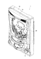
図1に示すように、遊技機1は、遊技機1を遊技場に設置するための外枠10と、外枠10の前面側に開閉可能に設けられた内枠20と、遊技球が流下する遊技領域が設けられた遊技盤30と、回転操作されることによって遊技領域に遊技球を発射するように構成された発射ハンドル9とを具備する。
As shown in FIG. 1, the gaming machine 1 includes an
また、遊技盤30上の遊技領域には、誘導部材3と、誘導部材4と、一般入賞口5と、始動口6と、大入賞口7と、アウト口8とが設けられている。なお、図1においては、遊技領域に設けられた釘は省略されている。
In the game area on the
誘導部材3は、遊技盤30上の遊技領域の上方に設けられ、遊技領域に発射された遊技球の流下方向を変化させるものである。また、誘導部材4は、誘導部材3の下方に設けられ、遊技領域に発射された遊技球の流下方向を変化させるものである。
The
一般入賞口5は、一般入賞口5に遊技球が入球すると、所定数(例えば、15個)の遊技球が賞球として払い出されるように構成されている。 The general winning opening 5 is configured such that when a game ball enters the general winning opening 5, a predetermined number (for example, 15) of game balls are paid out as winning balls.
始動口6は、始動口6内に設けられた始動領域を遊技球が通過すると、遊技状態を大当り状態に移行させるか否かの判定(大当り判定)に用いる乱数が抽出されるように構成されている。また、始動口6は、始動口6に遊技球が入球すると、所定数(例えば、10個)の遊技球が賞球として払い出されるように構成されている。
The
大入賞口7は、遊技状態が大当り状態に移行されると、所定の条件に従って開閉するように構成されている。また、大入賞口7は、大入賞口7に遊技球が入球すると、所定数(例えば、15個)の遊技球が賞球として払出されるように構成されている。
The
アウト口8は、一般入賞口5、始動口6及び大入賞口7等の何れにも入球しなかった遊技球を受け入れるものである。
The out port 8 receives a game ball that has not entered any of the general winning port 5, the
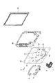
図2は、本実施形態における遊技機1に設けられた遊技盤30、スペーサ40及び液晶表示装置50の配置関係を示す斜視図である。図2に示すように、遊技盤30の裏面側には、スペーサ40が配置され、該スペーサ40の裏面側には、液晶表示装置50が配置されている。
FIG. 2 is a perspective view showing an arrangement relationship of the
具体的には、遊技盤30は、所定の透明性(例えば、光の透過率が50%以上)を有する合成樹脂(例えば、ポリカーボネート)によって構成されている。また、遊技盤30には、誘導部材3を取り付けるための取付孔31と、誘導部材4を取り付けるための取付孔32と、始動口6を取り付けるための取付孔33と、大入賞口7を取り付けるための取付孔34とが設けられている。さらに、遊技盤30には、遊技領域に発射された遊技球の流下方向を変化させる複数の釘2(図2では、1本のみを図示)を取り付けるための釘下孔35が設けられている。
Specifically, the
スペーサ40は、遊技盤30に取り付けられた始動口6や大入賞口7の裏機構(ソレノイド等)が液晶表示装置50に接触しないようにするためのスペースを、遊技盤30と液晶表示装置50との間に形成するためのものである。
The spacer 40 is a space for preventing the back mechanism (solenoid or the like) of the
液晶表示装置50は、識別情報(例えば、特別図柄)の可変表示、遊技を盛り上げるための演出画像等を表示する。なお、遊技者は、液晶表示装置50に表示された所定の画像を、所定の透明性を有する遊技盤30を介して視認することができる。
The liquid
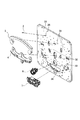
図3は、本実施形態における遊技盤30の拡大斜視図である。図3に示すように、遊技盤30には、上述した取付孔31、取付孔32、取付孔33、取付孔34及び釘下孔35が設けられている。
FIG. 3 is an enlarged perspective view of the
具体的には、誘導部材3は、取付孔31に嵌め込まれるとともに、誘導部材3に設けられた所定の爪(不図示)が遊技盤30の裏面側に係止されることによって、遊技盤30に固定される。なお、誘導部材3は、ねじ止めされることによって、遊技盤30に固定されてもよい。
Specifically, the
誘導部材4は、取付孔32に嵌め込まれるとともに、誘導部材4に設けられた所定の爪(不図示)が遊技盤30の裏面側に係止されることによって、遊技盤30に固定される。なお、誘導部材4は、ねじ止めされることによって、遊技盤30に固定されてもよい。
The guide member 4 is fixed to the
始動口6は、取付孔33に嵌め込まれるとともに、始動口6に設けられた所定の爪(不図示)が遊技盤30の裏面側に係止されることによって、遊技盤30に固定される。なお、始動口6は、ねじ止めされることによって、遊技盤30に固定されてもよい。
The
大入賞口7は、取付孔34に嵌め込まれるとともに、大入賞口7に設けられた所定の爪(不図示)が遊技盤30の裏面側に係止されることによって、遊技盤30に固定される。なお、大入賞口7は、ねじ止めされることによって、遊技盤30に固定されてもよい。
The
釘2は、螺旋状に形成された凸部(ねじ山)を有し、螺旋状に形成された凹部(ねじ谷)を内側に有する釘下孔35にねじ込まれることによって、遊技盤30に固定される。
The nail 2 has a convex portion (screw thread) formed in a spiral shape, and is fixed to the
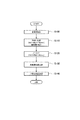
(遊技盤の形成方法)
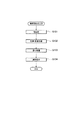
以下において、本実施形態における遊技盤30の形成方法について、図面を参照しながら説明する。図4は、本実施形態における遊技盤30の形成方法を示すフロー図である。
(Game board formation method)
Below, the formation method of the
図4に示すように、ステップ100において、所定の透明性(例えば、光の透過率が50%以上)を有する合成樹脂(粒上の材料)を、板状の合成樹脂板(第1段階)を形成する押出し成形機に投入する。なお、所定の透明性を有する合成樹脂とは、ポリカーボネート、アクリル系樹脂、ポリエチレン等の合成樹脂である。
As shown in FIG. 4, in
ステップ110において、押出し成形機は、投入された合成樹脂を加工することによって、板状の合成樹脂板(第1段階)を成形する。具体的には、押出し成形機は、投入された合成樹脂に熱を加えることによって、該合成樹脂を溶融するとともに、溶融された合成樹脂(溶融樹脂)を、金型を通じて押出す。また、押出し成形機は、金型を通じて押出された溶融樹脂を冷却し、板状の合成樹脂板(第1段階)を成形する。
In
なお、合成樹脂板(第1段階)は、1枚の合成樹脂板(第1段階)から所定枚数(本実施形態では4枚)分の基盤(遊技盤30)を切り出すことができる大きさ(例えば、880mm×925mm×10.5mm)を有するものとする。また、押出し成形機によって成形された合成樹脂板(第1段階)は、該合成樹脂板(第1段階)を切り離すダイシング装置に搬送される。 The synthetic resin plate (first stage) is large enough to cut out a predetermined number (four in this embodiment) of bases (game board 30) from one synthetic resin plate (first stage) ( For example, it shall have 880 mm x 925 mm x 10.5 mm). Further, the synthetic resin plate (first stage) formed by the extrusion molding machine is conveyed to a dicing apparatus that separates the synthetic resin plate (first stage).
ステップ120において、ダイシング装置は、押出し成形機によって成型された合成樹脂板(第1段階)を、所定枚数(本実施形態では4枚)の基盤(遊技盤30)に切り離す。なお、1枚の基盤の大きさは、428mm×450mm×10.5mmであるものとする。また、ダイシング装置によって切り離された各基盤は、基盤の表面に薄膜層を形成する装置(溶剤を塗布する塗布装置や塗布された溶剤を乾燥させる遠赤処理装置等)に搬送される。
In
ステップ130において、塗布装置は、光触媒物質(例えば、酸化チタン(TiO2))等を含む溶剤を基盤の表面側に噴射(スプレー)することによって、該溶剤を基盤の表面側に塗布する。また、遠赤処理装置は、基盤に塗布された溶剤を乾燥させることによって、基盤の表面側に薄膜層を形成する(薄膜層形成工程)。なお、この薄膜層形成工程の詳細については、後述ずる(図5を参照)。
In
なお、表面側及び裏面側に薄膜層が形成された基盤(合成樹脂板(第2段階))は、取付孔31〜取付孔34及び釘下孔35を形成するルータ加工装置に搬送される。
In addition, the board | substrate (synthetic resin board (2nd step)) in which the thin film layer was formed in the surface side and the back surface side is conveyed to the router processing apparatus which forms the attachment hole 31-the
ステップ140において、ルータ加工装置は、所定の加工データに基づいて、合成樹脂板(第2段階)を切削することによって、取付孔31〜取付孔34及び釘下孔35を形成する。
In
以下において、上述した薄膜層形成工程について、図面を参照しながら説明する。図5は、本実施形態における薄膜層形成工程を示すフロー図である。 Hereinafter, the above-described thin film layer forming step will be described with reference to the drawings. FIG. 5 is a flowchart showing a thin film layer forming step in the present embodiment.
図5に示すように、ステップ131において、前処理装置は、基盤の表面側に熱を加える処理(前処理)を行う。具体的には、前処理装置は、前処理装置に備えられたバーナー等によって基盤の表面側に熱を加えることによって、基盤の表面側にケイ素皮膜を形成する。 As shown in FIG. 5, in step 131, the pretreatment apparatus performs a treatment (pretreatment) for applying heat to the surface side of the substrate. Specifically, the pretreatment device forms a silicon film on the surface side of the substrate by applying heat to the surface side of the substrate with a burner or the like provided in the pretreatment device.
ステップ132において、除塵・除電装置は、基盤の表面側に付着している塵や基盤の表面に帯電している静電気を取り除く処理(塵除・除電処理)を行う。 In step 132, the dust removing / static eliminating device performs a process (dust removing / static eliminating process) for removing dust adhering to the surface side of the substrate and static electricity charged on the surface of the substrate.
ステップ133において、塗布装置は、光触媒物質(酸化チタン(TiO2))を含む溶剤を、基盤の表面側に噴射(スプレー)することによって、該溶剤を基盤の表面側に塗布する処理(塗布処理)を行う。例えば、塗布装置は、チタンアルコシキドを加水分解した後に、少量の塩酸等を加えた溶剤を、基盤の表面側に噴射する。 In step 133, the coating apparatus sprays a solvent containing a photocatalytic substance (titanium oxide (TiO2)) onto the surface side of the substrate, thereby applying the solvent to the surface side of the substrate (coating process). I do. For example, the coating apparatus sprays a solvent to which a small amount of hydrochloric acid or the like is added to the surface side of the substrate after hydrolyzing titanium alkoxide.
なお、塗布装置は、溶剤の入った溶剤槽に基盤を浸漬することによって、該溶剤を基盤の表面側に塗布してもよい(ディッピング)。 Note that the coating device may apply the solvent to the surface side of the base by dipping the base in a solvent tank containing the solvent (dipping).
ステップ134において、遠赤処理装置は、基盤の表面側に塗布された溶剤を乾燥させる処理(遠赤処理)を行う。具体的には、遠赤処理装置は、基盤の表面側に塗布された溶剤(光触媒物質(酸化チタン(TiO2))を含む溶剤)を乾燥させることによって、粒子の直径が1μm以下の酸化チタン(TiO2)によって構成された薄膜層を、基盤の表面側に形成する(ゾルゲル法)。
In
(遊技盤の構成)
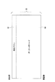
以下において、本実施形態における遊技盤30の構成について説明する。図6は、本実施形態における遊技盤30の構成を示す断面図である。
(Game board configuration)
Below, the structure of the
図6に示すように、遊技盤30は、所定の透明性を有する合成樹脂(ポリカーボネート)によって形成された基盤60と、光触媒物質(酸化チタン(TiO2))によって基盤60の表面側に形成され、所定の透明性を有する薄膜層61とによって構成されている。
As shown in FIG. 6, the
基盤60は、ポリカーボネートによって形成され、所定の透明性(光の透過率が50%以上)を有する。また、薄膜層61は、粒子の直径が1μm以下の酸化チタン(TiO2)によって形成され、所定の透明性(光の透過率が50%以上)を有する。
The
上述した薄膜層61は、ホール内の照明やホール外からの太陽光等に含まれる紫外線(波長が400nm以下)が照射されることによって、薄膜層61(遊技盤30)の表面側に付着した汚れ等(手垢やタバコのヤニ)を分解する。
The above-described
具体的には、薄膜層61は、紫外線が照射されることによって、電子及び正孔を生成し、生成された電子及び正孔は、水や酸素等と反応することによって、OHラジカルやスーパーオキサイドアニオン(O2 −)等の活性酸素を生成する。ここで、活性酸素のエネルギーは、120kcal/molであるのに対し、有機物等(薄膜層61の表面側に付着した汚れ等)を構成する分子(炭素−炭素、炭素−窒素、酸素−水素、窒素−水素)の結合エネルギーは、100kcal/mol前後である。従って、生成された活性酸素は、有機物等を構成する分子の結合を切り離すことができる。すなわち、薄膜層61は、紫外線の照射によって生成された活性酸素の酸化力・還元力によって、薄膜層61(遊技盤30)の表面側に付着した汚れ等を分解することができる。
Specifically, the
なお、基盤60の表面側に塗布される溶剤は、クロムやバナジウム等の金属イオンを加えた酸化チタン(TiO2)によって構成されていてもよい。このような溶剤によって形成された薄膜層61は、紫外線(波長が400nm以下)だけではなく、可視光線(波長が400nm以上)が照射されることによっても、活性酸素を生成し、薄膜層61の表面側に付着した汚れ等(有機物等)を分解することができる。
In addition, the solvent applied to the surface side of the
なお、薄膜層61は、TiO2に代えて、TiO2よりも酸素の含有比率が低い酸化チタン(TiO、Ti2O3、Ti3O5等)によって形成されていてもよい。また、薄膜層61は、TiO2に代えて、Zn、Zr、Hf等を主体とする酸化物無機物質によって形成されていてもよい。
Incidentally, the
さらに、薄膜層61は、基盤60の表面側に加えて、基盤60の裏面側に形成されていてもよい。
Furthermore, the
(遊技盤の作用、及び、効果)
本実施形態における遊技盤30によれば、光触媒物質(TiO2)によって形成された薄膜層61が基盤60の表面側に形成されていることにより、遊技盤30は、ホール内の照明やホール外からの太陽光の照射によって、遊技盤30の表面側に付着した汚れ(手垢やタバコのヤニ等)を、ホールの従業員等による拭き取り作業を必要とせずに除去することができる。
(Action and effect of game board)
According to the
また、基盤60の表面側に、所定の透明性を有する薄膜層61が形成されていることにより、遊技盤30は、液晶表示装置50に表示された所定の画像(識別情報の可変表示や演出画像等)を、該遊技盤30を介して遊技者に視認可能とすることができる。
In addition, since the
さらに、基盤60が、ポリカーボネートによって構成されていることにより、始動口6、大入賞口7及び釘2を遊技盤30に取り付けるための取付孔31〜取付孔34及び釘下孔35を、遊技盤を切削することによって形成する場合に、遊技盤30を容易に切削することができる。
Further, since the
また、遠赤処理装置が、基盤60に塗布された溶剤(光触媒物質(TiO2)等を含む)を遠赤処理(ステップ134)によって乾燥させるため、遠赤処理装置は、該溶剤を短時間で乾燥させることができる。
Further, since the far-red processing apparatus dries the solvent (including the photocatalytic substance (TiO 2 ) and the like) applied to the
1・・・遊技機、2・・・釘、3・・・誘導部材、3a、3b・・・誘導口、4・・・誘導部材、4a、4b・・・誘導口、5・・・一般入賞口、6・・・始動口、7・・・大入賞口、8・・・アウト口、9・・・発射ハンドル、10・・・外枠、20・・・内枠、30・・・遊技盤、31〜34・・・取付孔、35・・・釘下孔、40・・・スペーサ、50・・・表示装置、60・・・基盤、61・・・薄膜層 DESCRIPTION OF SYMBOLS 1 ... Game machine, 2 ... Nail, 3 ... Guide member, 3a, 3b ... Guide port, 4 ... Guide member, 4a, 4b ... Guide port, 5 ... General Winning port, 6 ... Starting port, 7 ... Large winning port, 8 ... Out port, 9 ... Launch handle, 10 ... Outer frame, 20 ... Inner frame, 30 ... Game board, 31-34 ... mounting hole, 35 ... nail pilot hole, 40 ... spacer, 50 ... display device, 60 ... base, 61 ... thin film layer
Claims (3)
前記遊技盤は、
所定の透明性を有する第1の合成樹脂によって形成された基盤と、
光触媒物質によって形成され、所定の透明性を有する薄膜層とによって構成されていることを特徴とする遊技機。 A gaming machine comprising a gaming board having a gaming area where gaming balls flow down, and a display device provided on the back side of the gaming board,
The game board
A base formed of a first synthetic resin having a predetermined transparency;
A gaming machine comprising a thin film layer formed of a photocatalytic substance and having a predetermined transparency.
The gaming machine according to claim 1, wherein the first synthetic resin is made of polycarbonate.
Priority Applications (1)
| Application Number | Priority Date | Filing Date | Title |
|---|---|---|---|
| JP2004119569A JP2005296471A (en) | 2004-04-14 | 2004-04-14 | Game machine |
Applications Claiming Priority (1)
| Application Number | Priority Date | Filing Date | Title |
|---|---|---|---|
| JP2004119569A JP2005296471A (en) | 2004-04-14 | 2004-04-14 | Game machine |
Publications (1)
| Publication Number | Publication Date |
|---|---|
| JP2005296471A true JP2005296471A (en) | 2005-10-27 |
Family
ID=35328724
Family Applications (1)
| Application Number | Title | Priority Date | Filing Date |
|---|---|---|---|
| JP2004119569A Pending JP2005296471A (en) | 2004-04-14 | 2004-04-14 | Game machine |
Country Status (1)
| Country | Link |
|---|---|
| JP (1) | JP2005296471A (en) |
Citations (9)
| Publication number | Priority date | Publication date | Assignee | Title |
|---|---|---|---|---|
| JPH09173783A (en) * | 1995-10-27 | 1997-07-08 | Matsushita Electric Ind Co Ltd | Flat glass, resin plate, manufacturing method thereof and pollutant removal method |
| JPH09313948A (en) * | 1996-05-28 | 1997-12-09 | Nippon Parkerizing Co Ltd | Resin or resin coating material having photocatalyst surface and method for producing the same |
| JPH10272231A (en) * | 1997-03-31 | 1998-10-13 | Sharp Corp | Gaming equipment |
| JPH1119281A (en) * | 1997-07-03 | 1999-01-26 | Taiyo Elec Co Ltd | Game machine |
| JPH11319579A (en) * | 1998-05-15 | 1999-11-24 | Toshiba Lighting & Technology Corp | Photocatalyst and lighting equipment |
| JP2000025156A (en) * | 1998-07-13 | 2000-01-25 | Sekisui Jushi Co Ltd | Protective film |
| JP2000176090A (en) * | 1998-12-17 | 2000-06-27 | Takeya Co Ltd | Method of attaching photocatalyst to pachinko machine part and pachinko machine part |
| JP2000185138A (en) * | 1998-12-22 | 2000-07-04 | Taiyo Elec Co Ltd | Gaming machine |
| JP2000198947A (en) * | 1999-01-06 | 2000-07-18 | Maruki Shokai:Kk | Weather-resistant member and method for forming protective film for member |
-
2004
- 2004-04-14 JP JP2004119569A patent/JP2005296471A/en active Pending
Patent Citations (9)
| Publication number | Priority date | Publication date | Assignee | Title |
|---|---|---|---|---|
| JPH09173783A (en) * | 1995-10-27 | 1997-07-08 | Matsushita Electric Ind Co Ltd | Flat glass, resin plate, manufacturing method thereof and pollutant removal method |
| JPH09313948A (en) * | 1996-05-28 | 1997-12-09 | Nippon Parkerizing Co Ltd | Resin or resin coating material having photocatalyst surface and method for producing the same |
| JPH10272231A (en) * | 1997-03-31 | 1998-10-13 | Sharp Corp | Gaming equipment |
| JPH1119281A (en) * | 1997-07-03 | 1999-01-26 | Taiyo Elec Co Ltd | Game machine |
| JPH11319579A (en) * | 1998-05-15 | 1999-11-24 | Toshiba Lighting & Technology Corp | Photocatalyst and lighting equipment |
| JP2000025156A (en) * | 1998-07-13 | 2000-01-25 | Sekisui Jushi Co Ltd | Protective film |
| JP2000176090A (en) * | 1998-12-17 | 2000-06-27 | Takeya Co Ltd | Method of attaching photocatalyst to pachinko machine part and pachinko machine part |
| JP2000185138A (en) * | 1998-12-22 | 2000-07-04 | Taiyo Elec Co Ltd | Gaming machine |
| JP2000198947A (en) * | 1999-01-06 | 2000-07-18 | Maruki Shokai:Kk | Weather-resistant member and method for forming protective film for member |
Similar Documents
| Publication | Publication Date | Title |
|---|---|---|
| JP7054239B2 (en) | Pachinko machine | |
| CN101557936A (en) | Manufacturing method of window for display device, window for display device and wireless terminal unit comprising the same | |
| TW201337316A (en) | Coated articles including anti-fingerprint and/or smudge-reducing coatings, and/or methods of making the same | |
| JP6813422B2 (en) | Game machine | |
| RU2007133738A (en) | TRACTION ELEMENT OF ELEVATOR INSTALLATION (OPTION) AND METHOD FOR ITS MANUFACTURE | |
| US20090308841A1 (en) | Pattern forming method, substrate processing method and mold structure replication method | |
| JP2005296471A (en) | Game machine | |
| CN108189610A (en) | Surface of shell forming method, housing and mobile terminal | |
| CN102323719A (en) | Continuous exposure method and device | |
| JP6067904B1 (en) | Method for manufacturing board case for gaming machine and board case for gaming machine | |
| JP2011045579A (en) | Game machine | |
| WO2018117122A1 (en) | Plate with printed layer, cover member, and display device | |
| JP4662261B2 (en) | Game board manufacturing method | |
| JP2000070535A (en) | Gaming machine | |
| JP5993893B2 (en) | Game machine | |
| JP5862905B2 (en) | Game machine | |
| KR200280766Y1 (en) | An instant lottery ticket of sticker type | |
| KR100957844B1 (en) | Manufacturing method of decoration mirror | |
| JP7054236B2 (en) | Pachinko machine | |
| JP7054238B2 (en) | Pachinko machine | |
| JP7039047B2 (en) | Pachinko machine | |
| JP7056956B2 (en) | Pachinko machine | |
| JP7039046B2 (en) | Pachinko machine | |
| JP2010280086A (en) | Processing method of glass product having resin coating film | |
| JP6267470B2 (en) | Game machine |
Legal Events
| Date | Code | Title | Description |
|---|---|---|---|
| A621 | Written request for application examination |
Free format text: JAPANESE INTERMEDIATE CODE: A621 Effective date: 20061207 |
|
| A131 | Notification of reasons for refusal |
Free format text: JAPANESE INTERMEDIATE CODE: A131 Effective date: 20091027 |
|
| A977 | Report on retrieval |
Free format text: JAPANESE INTERMEDIATE CODE: A971007 Effective date: 20091028 |
|
| A521 | Written amendment |
Free format text: JAPANESE INTERMEDIATE CODE: A523 Effective date: 20091222 |
|
| A02 | Decision of refusal |
Free format text: JAPANESE INTERMEDIATE CODE: A02 Effective date: 20100511 |
|
| RD02 | Notification of acceptance of power of attorney |
Free format text: JAPANESE INTERMEDIATE CODE: A7422 Effective date: 20110405 |