JP2005296462A - Sphere delivery device for gaming machine - Google Patents
Sphere delivery device for gaming machine Download PDFInfo
- Publication number
- JP2005296462A JP2005296462A JP2004119446A JP2004119446A JP2005296462A JP 2005296462 A JP2005296462 A JP 2005296462A JP 2004119446 A JP2004119446 A JP 2004119446A JP 2004119446 A JP2004119446 A JP 2004119446A JP 2005296462 A JP2005296462 A JP 2005296462A
- Authority
- JP
- Japan
- Prior art keywords
- sphere
- delivery device
- gaming machine
- unit
- guide
- Prior art date
- Legal status (The legal status is an assumption and is not a legal conclusion. Google has not performed a legal analysis and makes no representation as to the accuracy of the status listed.)
- Granted
Links
Images


Landscapes
- Pinball Game Machines (AREA)
- Slot Machines And Peripheral Devices (AREA)
Abstract
【課題】
本発明の第1の目的は、揚送装置と払出装置を一体化し、小型、安価かつ消費エネルギーが少ない遊技機の球体送り出し装置を提供することである。
本発明の第2の目的は、使用される球体を遊技機内で磨くことができる遊技機の球体送り出し装置を提供することである。
本発明の第3の目的は、球体磨きによって発生したゴミを自動的に排除できる遊技機の球体送り出し装置を提供することである。
【解決手段】
バラ積み状態で球体を保留する保留ボウル、前記保留ボウルから球体を受け入れ、一つずつ強制的に送り出す送り出し装置、前記送り出し装置から送り出された球体を列にして上方に案内する案内部、前記案内部の出口に配置した検出部、前記検出部の検出に基づいて前記送り出し装置を停止する制御部とを含む遊技機の球体送り出し装置である。
【選択図】図2【Task】
A first object of the present invention is to provide a ball delivery device for a gaming machine that integrates a lifting device and a payout device, and is small, inexpensive, and consumes less energy.
A second object of the present invention is to provide a sphere delivery device for a gaming machine that can polish the sphere used in the gaming machine.
A third object of the present invention is to provide a sphere delivery device for a gaming machine that can automatically eliminate dust generated by sphere polishing.
[Solution]
Reservation bowl for retaining spheres in a stacked state, a delivery device that accepts spheres from the retention bowl and forcibly sends them one by one, a guide unit that guides the spheres sent from the delivery device in a row, and the guidance A ball delivery device for a gaming machine, comprising: a detection unit disposed at an outlet of the unit; and a control unit that stops the delivery device based on detection by the detection unit.
[Selection] Figure 2
Description
本発明は、遊技機に用いる球体送り出し装置に関する。
詳しくは、遊技機の機構を簡単化し、安価に提供できる球体送り出し装置に関する。
さらに詳しくは、球体の検出装置を備えた球体送り出し装置に関する。
なお、本明細書で使用する「球体」の代表例は、パチンコ球である。
The present invention relates to a sphere delivery device used in a gaming machine.
More specifically, the present invention relates to a sphere delivery device that can simplify the mechanism of a gaming machine and provide it at a low cost.
More specifically, the present invention relates to a sphere delivery device provided with a sphere detection device.
A representative example of the “sphere” used in the present specification is a pachinko sphere.
遊技機内の下位に配置した貯留部から揚送装置によって上位に配置した上部貯留タンクにパチンコ球を送給して貯留し、入賞時に上部貯留タンクから落下させつつ払出装置で所定数を払い出す遊技機が知られている(例えば、特許文献1参照。)。 A game in which a pachinko ball is fed and stored from a storage unit arranged at a lower position in a gaming machine to an upper storage tank arranged at a higher level by a lifting device, and a predetermined number is paid out by a payout device while dropping from the upper storage tank at the time of winning a prize The machine is known (for example, refer to Patent Document 1).
前記従来技術において、球体は揚送装置によって上部貯留部に揚送され、別に設けられた払出装置で払い出される。
換言すれば、球体の積極的送り出し装置が二つ必要であり、設置スペースが大きくなると共に、コスト高であり、さらに消費エネルギーも大きいという問題がある。
In the prior art, the sphere is lifted to the upper storage portion by the lifting device, and is paid out by a separately provided dispensing device.
In other words, two positive ball feeding devices are required, and there are problems that the installation space becomes large, the cost is high, and the energy consumption is also large.
本発明の第1の目的は、揚送装置と払出装置を一体化し、小型、安価かつ消費エネルギーが少ない遊技機の球体送り出し装置を提供することである。
本発明の第2の目的は、使用される球体を遊技機内で磨くことができる遊技機の球体送り出し装置を提供することである。
本発明の第3の目的は、球体磨きによって発生したゴミを自動的に排除できる遊技機の球体送り出し装置を提供することである。
A first object of the present invention is to provide a ball delivery device for a gaming machine in which a lifting device and a payout device are integrated to be small, inexpensive, and consume less energy.
A second object of the present invention is to provide a sphere delivery device for a gaming machine that can polish the sphere used in the gaming machine.
A third object of the present invention is to provide a sphere delivery device for a gaming machine that can automatically eliminate dust generated by sphere polishing.
この目的を達成するため、請求項1の発明にかかる遊技機の球体送り出し装置は次のように構成されている。
バラ積み状態で球体を保留する保留ボウル、前記保留ボウルから球体を受け入れ、一つずつ強制的に送り出す送り出し装置、前記送り出し装置から送り出された球体を列にして上方に案内する案内部、前記案内部の出口に配置した検出部、前記検出部の検出に基づいて前記送り出し装置を停止する制御部とを含む遊技機の球体送り出し装置である。
In order to achieve this object, a ball delivery device for a gaming machine according to the invention of claim 1 is configured as follows.
Reservation bowl for retaining spheres in a stacked state, a delivery device that accepts spheres from the retention bowl and forcibly sends them one by one, a guide unit that guides the spheres sent from the delivery device in a row, and the guidance A ball delivery device for a gaming machine, comprising: a detection unit disposed at an outlet of the unit; and a control unit that stops the delivery device based on detection by the detection unit.
この構成において、保留ボウルにバラ積み状態に保留された球体は、送り出し装置によって一つずつ強制的に送り出され、案内部によって列状に案内される。
そして、案内部の出口から所定の装置に払い出される。
検出部は、案内部の出口から払い出される球体を検出する。
そして制御部は、その検出信号をカウントする。
そのカウント数が所定の数になった場合、制御部は球体送り出し装置を停止する。
換言すれば、送り出し装置は所定数の球体の払出装置と揚送装置を兼ね備えている。
したがって、一つの送り出し装置のみ設置すればよいので、装置は小型、かつ、安価であり、さらに、消費エネルギーも少ないという利点がある。
In this configuration, the spheres held in a bulk state in the holding bowl are forcibly sent one by one by the feeding device and guided in a row by the guide unit.
And it pays out to the predetermined | prescribed apparatus from the exit of a guide part.
The detection unit detects a sphere paid out from the exit of the guide unit.
And a control part counts the detection signal.
When the count reaches a predetermined number, the control unit stops the sphere delivery device.
In other words, the delivery device has a predetermined number of spherical dispensing devices and a lifting device.
Therefore, since only one delivery device needs to be installed, the device is advantageous in that it is small and inexpensive, and further consumes less energy.
請求項2の発明は、請求項1の発明において、前記案内部に球体磨き部を着脱可能に取り付けた遊技機の球体送り出し装置である。
この構成において、球体は案内部によって案内されつつ揚送される。
したがって、球体は、案内部の壁に着脱可能に取り付けられた球体磨き部に対し相対移動する。
換言すれば、球体は球体磨き部によって擦られつつ移動するので、自動的に磨かれる利点を有する。
また、球体磨き部は案内部に取り付けられるので、特別な装置を設けないので小型に形成できる利点を有する。
さらに、球体磨き部は案内部に着脱可能であるので、球体磨き機能が低下した場合、直ぐさま交換可能である。
A second aspect of the present invention is the sphere feeding device of a gaming machine according to the first aspect of the present invention, wherein a sphere polishing portion is detachably attached to the guide portion.
In this configuration, the sphere is lifted while being guided by the guide.
Therefore, the sphere moves relative to the sphere polishing portion detachably attached to the wall of the guide portion.
In other words, since the sphere moves while being rubbed by the sphere polishing portion, it has the advantage of being automatically polished.
In addition, since the sphere polishing portion is attached to the guide portion, there is an advantage that it can be formed in a small size without providing a special device.
Furthermore, since the sphere polishing part can be attached to and detached from the guide part, when the sphere polishing function is deteriorated, it can be replaced immediately.
請求項3の発明は、請求項2の発明において、前記案内部が、断面角形のパイプ遊技機の球体送り出し装置である。
この構成において、案内部が断面角形のパイプであるから、球体がこのパイプ内を移動する場合、角部において球体とパイプの間にスペースができる。
混入したゴミ等は、この角部空間に追いやられ、球体の通路から排除されるので、球体の移送を効率良く行うことができる。
According to a third aspect of the present invention, in the second aspect of the present invention, the guide portion is a sphere feeding device for a pipe game machine having a square cross section.
In this configuration, since the guide portion is a square pipe, when the sphere moves in the pipe, a space is created between the sphere and the pipe at the corner.
The mixed dust is driven into this corner space and removed from the passage of the sphere, so that the sphere can be transferred efficiently.
請求項4の発明は、請求項3の発明において、前記球体磨き部が、断面角形パイプの角部に配置されている遊技機の球体送り出し装置である。
この構成において、球体磨き部は、パイプの角部に配置されている。
換言すれば、前記したように角部の場合、パイプと球体の間に空間があるため、球体磨き部はその空間に配置される。
したがって、球体磨き部の設置用スペースを新たに設けなくともよいので、装置を小型化できる利点がある。
According to a fourth aspect of the present invention, in the third aspect of the invention, the sphere polishing portion is a sphere feeding device for a gaming machine in which the sphere polishing portion is arranged at a corner portion of a square cross-section pipe.
In this configuration, the sphere polishing portion is disposed at the corner of the pipe.
In other words, as described above, in the case of the corner portion, since there is a space between the pipe and the sphere, the sphere polishing portion is arranged in the space.
Therefore, it is not necessary to newly provide a space for installing the sphere polishing portion, and there is an advantage that the apparatus can be downsized.
請求項5の発明は、請求項3の発明において、前記案内部が、スパイラル状である遊技機の球体送り出し装置である。
この構成において、球体はパイプのねじれにより進行方向に対し直角方向にトルクを受けるので、進行方向に伸びる軸線の回りを回動する。
換言すれば、球体の周面が球体磨き部に対し相対移動するので、なんらの装置を設けずとも球体の全周を磨くことができる利点を有する。
A fifth aspect of the present invention is the sphere delivery device for a gaming machine according to the third aspect, wherein the guide portion has a spiral shape.
In this configuration, the sphere receives torque in a direction perpendicular to the traveling direction due to twisting of the pipe, and thus rotates around an axis extending in the traveling direction.
In other words, since the circumferential surface of the sphere moves relative to the sphere polishing portion, there is an advantage that the entire circumference of the sphere can be polished without providing any device.
請求項6の発明は、請求項2の発明において、前記案内部が、上下方向にループしている請求項2の遊技機の球体送り出し装置である。
この構成において、球体の通路が上下方向にループしているので、ループの底に内部のゴミが落下する。
したがって、この底部に配置した排出孔から、球体磨き部によって球体表面から取り除いたゴミを落下させることができる。
したがって、簡単な装置で通路内のゴミを排除することができる利点がある。
The invention according to claim 6 is the ball delivery device for a gaming machine according to claim 2, wherein the guide portion loops in the vertical direction.
In this configuration, since the spherical passage loops in the vertical direction, dust inside falls to the bottom of the loop.
Therefore, the dust removed from the surface of the sphere by the sphere polishing portion can be dropped from the discharge hole arranged at the bottom.
Therefore, there is an advantage that dust in the passage can be eliminated with a simple device.
バラ積み状態で球体を保留する保留ボウル、前記保留ボウルから球体を受け入れ、一つずつ強制的に送り出す送り出し装置、前記送り出し装置から送り出された球体を列にして上方に案内する案内部、前記案内部の出口に配置した検出部、前記検出部の検出信号に基づいて前記送り出し装置を停止する制御部とを含み、前記案内部が断面角形のパイプであり、前記パイプの角部に球体磨き部を配置した遊技機の球体送り出し装置である。 Reservation bowl for retaining spheres in a stacked state, a delivery device that accepts spheres from the retention bowl and forcibly sends them one by one, a guide unit that guides the spheres sent from the delivery device in a row, and the guidance And a control unit that stops the delivery device based on a detection signal of the detection unit, and the guide unit is a pipe having a square cross section, and a sphere polishing unit at a corner of the pipe This is a ball delivery device for a gaming machine in which is arranged.
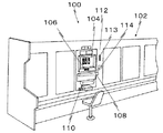
図1は本発明の実施例の球体送り出し装置が内蔵される遊技機列の斜視図である。
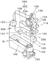
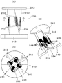
図2は本発明の実施例の球体送り出し装置を内蔵したゲーム機の概略斜視図である。
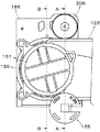
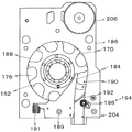
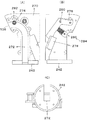
図3は、実施例の球体送り出し装置の平面図である。
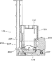
図4は、図3におけるA―A線断面図である。
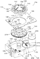
図5は、実施例の球体送り出し装置の分解斜視図である。
図6は、図3におけるB―B線断面図である。
図7は、図6におけるC―C線断面図である。
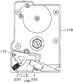
図8は、実施例の球体送り出し装置の裏面図である。
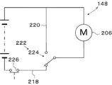
図9は、実施例の制動部の回路図である。
図10は、実施例の球体磨き部の正面図、D―D線断面図及び縦断面斜視図である。
図11は、実施例の検知部の正面図、背面図及び裏面図である。
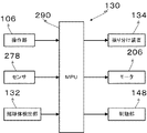
図12は、実施例の制御部のブロック図である。
図13は、実施例の作用説明用のフローチャートである。
FIG. 1 is a perspective view of a gaming machine row in which a sphere delivery device according to an embodiment of the present invention is built.
FIG. 2 is a schematic perspective view of a game machine incorporating the sphere feeding device according to the embodiment of the present invention.
FIG. 3 is a plan view of the spherical body delivery device of the embodiment.
4 is a cross-sectional view taken along line AA in FIG.
FIG. 5 is an exploded perspective view of the spherical body feeding device of the embodiment.
6 is a cross-sectional view taken along line BB in FIG.
7 is a cross-sectional view taken along line CC in FIG.
FIG. 8 is a back view of the sphere feeding device of the embodiment.
FIG. 9 is a circuit diagram of the braking unit of the embodiment.
FIG. 10 is a front view, a DD line cross-sectional view, and a vertical cross-sectional perspective view of the sphere polishing portion of the embodiment.
FIG. 11 is a front view, a rear view, and a rear view of the detection unit of the embodiment.
FIG. 12 is a block diagram of the control unit of the embodiment.
FIG. 13 is a flowchart for explaining the operation of the embodiment.
図1において、複数の遊技機100が列設され、島102を構成している。
次に遊技機100の概要を図1及び2を参照して説明する。
遊技機100は、その正面に上から順に、ゲーム内容等の表示部104、操作部106、球体投入皿108及び入賞球払出皿110が配置されている。
In FIG. 1, a plurality of
Next, an outline of the
The
操作部106は、遊技の開始、遊技形式の選択等の指示信号を出力し、例えば、複数の押しボタンスイッチにより構成されている。
球体投入皿108は、賭け球体をバラ状態で受け入れ、底面の傾斜により所定の投入口に順次供給する機能を有する。
入賞球払出皿110は、払い出された入賞球をバラ状体で保留する機能を有する。
The
The
The winning
隣接する遊技機100との間に台間装置112が配置され、購入球体の払出ノズル114が球体投入皿108の上方に配置されている。
詳述すれば、台間装置112の受け入れ口113に所定金額、又はプリペイドカードを挿入し、受け入れた所定金額に対し所定数の球体が払出ノズル114に払い出される。
払い出された球体は、払出ノズル114によって球体投入皿108に供給される。
An
More specifically, a predetermined amount or a prepaid card is inserted into the
The dispensed sphere is supplied to the
遊技機100の内部には、球体送り出し装置120が配置されている。
球体送り出し装置120は、保留ボウル122、送り出し部124、案内部126、検出部128及び制御部130を含んでいる。
保留ボウル122は、横長矩形であり、底部が送り出し部124側へ傾斜しており、球体Bをバラ積み状態で保留する。
A
The spherical
The holding
送り出し部124は、保留ボウル122から受け取った球体Bを一つずつ送り出す機能を有している。
案内部126は、送り出し部124により送り出された球体Bを一列に並べて上方へ案内する機能を有する。
検出部128は、案内部126の先端から払い出される球体Bを検出する機能を有する。
The
The
The
制御部130は、検出部128及び賭球体検出部132並びに操作部106から信号を受け、選択的に送り出し部124及び振り分け部134に制御信号を出力する。
賭球体検出器132は、球体投入皿108から受け入れた球体Bを、操作部106からの賭球体受け入れ指示に基づいて所定数を計数し、保留ボウル122へ送り出すと共に賭球体検出信号を制御部130に出力する。
The
The betting
振分装置134は、案内部126の出口136から払い出された球体Bを払出ノズル114への通路138又は入賞球払出皿110への通路140へ選択的に振り分ける機能を有している。
The
次に、図2から図8を参照して送り出し部124を説明ずる。
送り出し部124は、分離部142、押出部144、駆動部146及び制動部148を含んでいる。
Next, the
The
まず、分離部142を説明する。
分離部142は、バラ積み状態の球体Bを一個づつ区分けする機能を有している。
実施例において分離部142は、保留ボウル122に隣接配置され、かつ、上下方向に伸びるシリンダ状の保留部150の底部に配置された円板形の分離ディスク152である。
保留部150の上部開口は、通常、着脱可能な蓋151により閉止されている。
First, the
The
In the embodiment, the
The upper opening of the holding
分離ディスク152は、回転中心部が円錐状に上方に凸に形成された滑落部154、その周囲にリング状に配置された平板部156を有している。
滑落部154には、等角度間隔で攪拌突起158が形成されている。
本実施例において攪拌突起158は、120度間隔で回転軸線から周方向に伸びるリブ状の突起である。
The
On the sliding
In this embodiment, the stirring
平板部156は、その周縁部が保留部150の下に配置されている。
滑落部154の周囲に分離ディスク152の回転軸線を中心とする凹溝160が形成されている。
複数の通孔162が回転軸線を中心とする同一円上に等間隔で凹溝160に形成されている。
The peripheral portion of the
A
A plurality of through
換言すれば、通孔162の間にはリブ165が位置している。
通孔162の周方向の幅は、球体Bの直径よりも僅かに大きく、長さは球体Bの直径の二倍以下に形成され、かつ、滑落部154及び平板部156の上面から滑らかな曲面で接続されている。
換言すれば、通孔162には球体1個のみが位置することができる。
In other words, the
The circumferential width of the through-
In other words, only one sphere can be positioned in the through
次に押出部144を説明する。
押出部144は、分離ディスク152とほぼ同径の円板状の押出ディスク164である。
押出ディスク164の上面には、押出ディスク164の回転軸線から周方向にインボリュート曲線状に伸びる保持溝166が通孔162に相対して形成されている。
換言すれば、所定の高さの下押出条168がインボリュート曲線状に伸びている。
なお、下押出条168は、球体Bをスムーズに移動させることが出来る場合、直線又は弧状に形成されることができる。
Next, the extruding
The extruding
A holding
In other words, the
In addition, the
分離ディスク152の裏面にも上押出条170が下押出条168に相対して形成されている。
これら分離ディスク152と押出ディスク164は、ボールベアリング172を挟んで一体化され、送出ディスク174を構成している。
したがって、下押出条168、上押出条170、分離ディスク152の下面及び押出ディスク164上面によって囲まれ、周面が開口した保持空間176が形成されている。
An upper
The
Therefore, a holding
押出ディスク164は、ベース178の上面に形成された円形穴180内に配置されている。
円形穴180の中央に固定軸182がほぼ垂直に固定され、その上端部にベアリング172が取り付けられている。
これにより、送出ディスク174は回転自在に支持されている。
The
A fixed
As a result, the
円形穴180の周側から中心部に向かって伸びる案内片184を有する案内プレート186がベース178の上面に固定されている。
案内プレート186は、案内片184、円形の案内孔188及び案内片184と案内孔188とにより形成した導出通路190とを有する。
なお、案内片184は、ベース178に固定した軸189にピボット可能に取付け、かつ、付勢体191、例えばスプリングによって図7において時計方向へ付勢され、図7に示す位置でストッパ(図示せず)により停止されている。
案内片184に球体Bが衝突した場合、案内片184が僅かにスプリング力に反して回動し、衝突のショックが緩和される。
A
The
The
When the sphere B collides with the
案内片184の先端は、分離ディスク152と押出ディスク164との間に形成された溝196に配置され、かつ、保持空間176の奥壁近傍に位置している。
したがって、通孔162に落下した球体Bは、押出ディスク162の保持溝166の底に支えられ、下押出条168及び上押出条170に押され、その直径部を案内孔188に案内されつつ送出ディスク174の回転ととも回動される。
The leading end of the
Therefore, the sphere B that has fallen into the through
そして、球体Bは案内片184に誘導され、導出路190を通って送出ディスク174の周方向に移動する。
導出路190は、球体Bの直径よりも僅かに幅が広く形成されている。
したがって、球体Bは導出路190を一列に並んで移動する。
導出路190に相対する円形穴180の周壁が開口され、出口開口192が形成されている。
Then, the sphere B is guided by the
The lead-out
Accordingly, the sphere B moves along the lead-out
A peripheral wall of the
出口開口192の近傍に球体切り装置194が配置されている。
球体切装置194は、ガイドローラ196、揺動レバー198、付勢体200及びセンサ202を含んでいる。
ガイドローラ196は、レバー198の一端に取付けられている。
A
The
The
レバー198は、ベース178の裏面側の凹部に配置されている。
レバー198は、スプリングである付勢体200によって図8において反時計方向に付勢されている。
これにより、ガイドローラ196は、出口開口192の近傍に配置され、出口通路204内の位置に保持される。
The
The
As a result, the
出口通路204は、導出路190と同様に球体Bが一列で移動可能である。
また、ガイドローラ196は、球体Bによって付勢体200の付勢力に反して出口通路204外に移動可能である。
したがって、球体切り装置194を通過した球体Bは、戻ることができない。
なお、センサ202は、配置せずとも良い。なぜなら、その機能は検出部128のセンサ278で代用可能であるから。
In the
Further, the
Therefore, the sphere B that has passed the
Note that the
次に駆動部146を説明する。
駆動部146は、送出ディスク174を所定速度で回転する機能を有する。
駆動部146は、電気モータ206及び伝動機構208を含んでいる。
Next, the
The
The
電気モータ206は、ベース178に倒立状態に固定され、その出力軸に固定した出力ギヤ207を有している。
伝動機構208は、円形穴180に隣接して形成したギヤ穴210内に直立する固定軸212に回転自在に取り付けた大径ギヤ214と一体の小径ギヤ216を含んでいる。
The
The
出力ギヤ207は、大径ギヤ214に噛み合い、小径ギヤ216は押出ディスク164の外周に形成したギヤ218に噛み合っている。
したがって、送出ディスク174は、電気モータ206によって伝動機構208を介して回転される。
The
Accordingly, the
次に、制動部148を図9を参照して説明する。
制動部148は、所定数の球体Bが払い出された後、送出ディスク174を急速停止し、球Bが過払いされないようにする機能を有する。
したがって、制動部148は、同様の機能を有する他の装置に変更することができる。
Next, the
The
Therefore, the
制動部148は、電気モータ206の給電回路218をショートさせることにより、電気モータ206に制動力を付与する電気ブレーキユニット220を用いることができる。
The
電気ブレーキユニット220は、電動モータ206の給電回路218において、モータ206と並列に接続されたスイッチングユニット222を含んでいる。
スイッチングユニット222は、本実施例ではスイッチ224であるが、同様の機能を有する他のスイッチング手段に変更することができる。
The
The
給電回路218には、ゲーム機の制御装置(図示せず)からの指令で開閉されるスイッチ226が直列に接続されている。
スイッチ224が閉じられた場合(図9の状態)、給電回路218は、閉回路になり、モータ206が所定の方向に回転される。
このとき、電気ブレーキユニット220は開放回路のため機能しない。
スイッチ224が開放され、スイッチングユニット222が閉になった場合、電気ブレーキユニット220は閉回路になる。
A
When the
At this time, the
When the
この状態において、送出ディスク174の慣性回転によりモータ206は発電機として機能し、電気ブレーキユニット220に電流が流れる。
電動モータ206は、閉状態の電気ブレーキユニット220によってショートされるため、発電機としての電動モータ206の負荷が最大になり、制動力が伝動機構208を介して送出ディスク174に加わる。
In this state, the
Since the
結果として、送出ディスク174は、僅かな慣性回転量で停止する。
前記電気ブレーキユニット220のみで制動力が不足する場合、モータ206から押出ディスク164の間の伝動機構208に電磁ブレーキユニット、若しくは、機械的ブレーキユニットを追加し、又は、それらに置き換えることができる。
制動力が不足する場合とは、例えば、余計に球体Bが出口136から払い出される場合である。
As a result, the
When the braking force is insufficient with only the
The case where the braking force is insufficient is, for example, a case where the sphere B is paid out from the
次に案内部126を図4を参照して説明する。
案内部126は、送り出し部124によって送り出された球体Bを一列に整列して上方に案内する機能を有する。
出口通路204に案内パイプ230が接続されている。
案内パイプ230は、ほぼ水平の出口通路204からほぼ垂直方向に立ち上がる湾曲部232と垂直上方に伸びる直線部234とを含んでいる。
Next, the
The
A
The
これら通路235は、断面矩形であって、球体Bの直径よりも僅かに大きい内法寸法を持っている。
直線部234は、所定長さのパイプ片を所定数接続することにより、その長さを段階的に設定可能にすることが望ましい。
案内パイプ230の断面は、円形、三角形、四角形及び五角形であってもよい。
しかし、後述の球体磨き部等との関係で角形が好ましい。
These
It is desirable that the
The cross section of the
However, a square shape is preferable in relation to a sphere polishing portion described later.
次に案内部126に配置した球体磨き部236を図10を参照して説明する。
球体磨き部236は、球体Bの案内機能と磨き機能とを有している。
球体磨き部236は、所定長さの角パイプ238及び球体磨き部材240とを含んでいる。
Next, the
The
The
角パイプ238は、両端のフランジ部242をネジ等の固定手段で固定することにより適宜数接続することができる。
角パイプ238のパイプの通路254の寸法は、通路235と同一であるが、スパイラル状である。
このスパイラル状角パイプ238は、図10(C)に示すように、縦方向に二分割した部品を組み合わせて構成することにより、製造が容易である。
しかし、直線部234と同様直線的に形成することができる。
The
The dimension of the
As shown in FIG. 10 (C), the spiral
However, like the
球体磨き部材240は、断面五角形の基材244に合成繊維からなるファイバー246の基部を束ねて埋め込み、ブラシ248を構成している。
基材244は、樹脂により成型し、僅かに弾性を有している。
角パイプ238の角部250に基材244よりも僅かに小さい矩形の装着孔252を形成してある。
The
The
A rectangular mounting
装着孔252は、図10(B)に示すように、各角部250に形成してもよいが、選択した少なくとも一以上の角部250に配置してもよい。
また、装着孔252を複数形成する場合、同一の角部250に形成すること、球体Bの進行方向に対し下流側にずれるよう螺旋状に形成すること、又は、ランダムに形成することができる。
The mounting
Further, when a plurality of mounting
しかし、装着孔252を螺旋状に形成した場合、球体Bに対しブラシ248によってその進行方向線回りの回転トルクを連続的に一方向に付与できる。
結果として、球体Bがその方向に僅かずつ回動されるため、球体Bの全周をブラシ248によって磨くことができる効果がある。
However, when the mounting
As a result, since the sphere B is slightly rotated in that direction, the entire circumference of the sphere B can be polished with the
基材244は、装着孔252に押し込まれ、装着孔252と基材244との間の摩擦力により保持される。
しかし、基材244の背面をサポータ(図示せず)によって押さえることにより抜け止めをすることが好ましい。
The
However, it is preferable to prevent the
したがって、基材244は装着孔252に対し着脱自在である。
換言すれば、ブラシ248が汚れ、又は、摩耗した場合、容易に交換することができる。
球体Bが球体磨き部236の球体通路254を通る場合、その周面はブラシ248の先端によって擦られる。
Accordingly, the
In other words, if the
When the sphere B passes through the
したがって、球体Bの表面に付着している油等は、ブラシ248に掻き取られ、球体Bは磨かれる。
ブラシ248が螺旋状に配置された場合、ブラシ248から球体Bに進行方向線回りのトルクが付与されるので、球体Bはその方向に回るため、球体Bの全周を磨くことができる。
Accordingly, oil or the like adhering to the surface of the sphere B is scraped off by the
When the
実施例のように、角パイプ238にした場合、通路254は矩形であり、球体Bは円であるため、角部に空間が形成される。
その空間に磨き部材240としてのブラシ248を配置することにより、特別な装置を設けること無く配置できる利点がある。
また、掻き落とされた油分等の塊がその空間を落下することが出来るので、排出物を効果的に排出することができる。
In the case of the
By arranging the
Moreover, since the lump of oil etc. which were scraped off can fall in the space, discharged | emitted matter can be discharged | emitted effectively.
次に排出部260を図2を参照して説明する。
排出部260は、球体Bに付着しているゴミ等を案内部126から排出する機能を有する。
球体磨き部236の下流に排出部260が配置されている。
排出部260は、ループ状のパイプ262である。
Next, the
The
A
The
パイプ262は、通路235と同一寸法であって、上下方向にループするループ通路264を有し、その通路264の最下部に排出孔266が形成されている。
したがって、排出孔266から球体Bに付着して来たゴミ等が離脱し、角部の空間を通ってループの最下部に落下し、さらに、排出孔266から落下することができる。
排出部260の下流に検出部128が配置されている。
The
Accordingly, the dust or the like adhering to the sphere B is detached from the
A
次に検出部128を図11を参照して説明する。
検出部128は、払い出される球体Bを検出する機能を有する。
したがって、同様の機能を有する他の装置に変更することができる。
実施例の検出部128は、払出ベース270に形成された倒立J形の払出通路272、被動ローラ274、レバー276及びセンサ278を含んでいる。
通路272は通路235と同一寸法である。
Next, the
The
Therefore, it can be changed to another device having the same function.
The detecting
The
被動ローラ274は、回動軸280に固定されたL形のレバー276の一端に固定された軸282に回転自在に取り付けられている。
被動ローラ274は、払出通路272に位置する待機位置と通路272外の被動位置に移動することができる。
The driven
The driven
レバ276は、付勢手段284、例えばスプリング286によって図11(B)おいて時計方向に付勢されている。
換言すれば、被動ローラ274はスプリング286によって待機位置に向かって付勢され、払出ベース270のストッパ(図示せず)によって係止されて前述の待機位置に保持される。
The
In other words, the driven
センサ278は、レバー276の他端の回動経路に相対して払出ベース270に固定されている。
被動ローラ274が払出通路272の外に押し出されたとき、したがって、レバー276が待機位置から所定角度回動された場合、レバ276の一端がセンサ278によって検知される。
The
When the driven
センサ278は、レバ276の一端を検知した場合、検知信号を出力する。
検出部128は、払出ベース270を通路272の軸線回りに回動可能に設け、アクチュエータによって選択的に所定の位置に回動させることにより出口136の位置を変更することができる。
When the
The
この位置変更により、球体投入皿108または入賞球払出皿110に選択的に払い出すことが出来る。
この場合、検出部128は、振り分け部134を兼ねることになる。
By changing the position, it is possible to selectively pay out to the
In this case, the
次に制御部130を図12を参照して説明する。
制御部130は、マイクロプロセッサ290であり、操作部106、センサ278及び賭球体検出部132から信号を受けとり、所定の処理を行った後、振り分け部134、球体送り出し装置120のモータ206及び制動部148を制御する機能を有している。
Next, the
The
換言すれば、記憶した処理プログラムにより、操作部106、センサ278及び賭球体検出部134からの信号に基づいて、振り分け装置134の振り分け及びモータ206の起動停止を制御する。
In other words, based on the signals from the
つぎに、本実施例の作用を図13のフローチャートを参照しつつ説明する。
まずステップS11において、台間装置112の受け入れ口113に投入された現金又はプリペイドカードが識別される。
これら現金又はカードを識別した場合、購入可能な金額を判別し、ステップS12に進む。
Next, the operation of the present embodiment will be described with reference to the flowchart of FIG.
First, in step S11, the cash or prepaid card inserted into the receiving
When the cash or card is identified, the purchaseable amount is determined, and the process proceeds to step S12.
次にステップS13において、操作部106の購入ボタンが押されたか判別する。
購入ボタンが押された場合、ステップS13に進み、振り分け装置134を球体投入皿108側に切り換える。
次にステップS14において、送り出し部124のモータ206を起動する。
この処理と並行して受け入れた現金を収納し、又は、プリペイドカードに残金が記憶される。
Next, in step S13, it is determined whether the purchase button on the
When the purchase button is pressed, the process proceeds to step S13, and the
Next, in step S14, the
The cash received in parallel with this processing is stored, or the balance is stored in the prepaid card.
モータ206の起動によって、伝動機構208を介して送出ディスク174が回転される。
送出ディスク174の回転により、その上に載っている多数の球体Bは、通孔162に落下する。
When the
Due to the rotation of the
図2に示すように、保留部150の下端開口は複数の通孔162に相対しているので、重力で落下するにも関わらず、球体Bは同時に複数の通孔162に落下出来る。
このため、送出ディスク174が高速回転しても通孔162には必ず球体Bが保留されているため、それら球体Bは歯抜けすることなく払い出だされる。
As shown in FIG. 2, since the lower end opening of the retaining
For this reason, even if the
送出ディスク174の回転により、攪拌突起158が一体に移動し、球体Bを突き上げる。
結果として、球体Bが攪拌され、通孔162に落下するので払出の効率が高まる。
したがって、保持空間176に球体Bが保留されない事態を防ぐことができるので、単位時間当たりの払出数を増加することができる。
Due to the rotation of the
As a result, the sphere B is agitated and falls into the through-
Therefore, since the situation where the sphere B is not held in the holding
球体Bは、高速度で移動しているので、通孔162において、その慣性により落下量が少ない場合がある。
その場合、球体Bは通孔162が十分に長いので、保持空間176に確実に落下する。
Since the sphere B is moving at a high speed, the amount of fall may be small in the through
In that case, since the through-
保持空間176に落下した球体Bは、案内孔188によってガイドされつつ下押出条160及び上押出条170によって押されるので、その下面を保持溝166底部に支えられて送出ディスク174とともに移動する。
Since the sphere B that has fallen into the holding
球体Bが案内片184に達した場合、送出ディスク174と同方向の移動は案内片184によって阻止されるので、案内片184によって送出ディスク174の周方向の導出路190に案内され、出口開口192を通って出口通路204に払い出される。
When the sphere B reaches the
球体Bは出口開口192を通過した直後、ガイドローラ196を押すので、レバー198の一端部がセンサ202に近接し、センサ202はカウント信号を出力する。
球体Bが通過した後、ローラ196、したがってレバー198はスプリング200によって元の位置に戻され、次の払出に備える。
したがって、球体Bが導出路190に戻ることはない。
Immediately after passing through the
After the sphere B has passed, the
Therefore, the sphere B does not return to the lead-out
センサ202からの信号が周期的に出力しない場合、エラーと判断し、モータ206を停止することができる。
送出ディスク174により順次送り出される球体Bは、湾曲部232、直線部234、球体磨き部236、排出部260及び検出部128の通路を一列に順次押し上げられ、被動ローラ274に達する。
When the signal from the
The sphere B sequentially delivered by the
被動ローラ274は、移動する球体Bによって待機位置から被動位置に移動される。
被動ローラ274と球体Bとの接触部が直径部を超えた場合、スプリング286によってレバー276が待機位置へ急速に移動される。
これにより、球体Bは勢いよく出口136から払い出される。
The driven
When the contact portion between the driven
As a result, the sphere B is vigorously paid out from the
払い出された球体Bは、通路138及び払出ノズル114を経由して球体投入皿108に供給される。
レバー276の検知位置への移動により、センサ278が検知信号を出力する。
ステップS15において、この検知信号が計数され、ステップS16において所定の払出数と比較される。
The discharged sphere B is supplied to the
As the
In step S15, this detection signal is counted and compared with a predetermined number of payouts in step S16.
所定の払出数に満たない場合、ステップS15に戻り、所定の払出数になるまで払出が行われる。
ステップS16において所定の払出数になった場合、ステップS17に進み、モータ206が停止され、かつ、制動部148が作動される。
When the predetermined number of payouts is not reached, the process returns to step S15, and payout is performed until the predetermined number of payouts is reached.
When the predetermined number of payouts is reached in step S16, the process proceeds to step S17, the
換言すれば、所定数の球体Bが払い出された場合、モータ206が停止され、電気ブレーキユニット220が作動して送出ディスク174は急速停止する。
したがって、送出ディスク174は急速停止されるので、球体Bの過払出を生じない。
In other words, when a predetermined number of spheres B are paid out, the
Therefore, since the
次に、操作部106の遊技開始ボタンが押されたケースを説明する。
ステップS21において開始ボタンが押されない場合、ステップS11に戻る。
遊技開始ボタンが押された場合、ステップS22に進む。
ステップS22において、賭球体検出部134において所定数の賭球体を検出した場合、ステップS23に進み、遊技が開始される。
Next, a case where the game start button of the
If the start button is not pressed in step S21, the process returns to step S11.
When the game start button is pressed, the process proceeds to step S22.
In step S22, when a predetermined number of betting balls are detected by the betting
次に遊技を開始後、ステップS24において入賞が判別される。
入賞しない場合、ステップS11に戻る。
入賞した場合、振り分け装置134を入賞球払出皿110側に切り換える。
次にステップS26においてモータ206を起動させ、前述のように出口136から球体Bを一個ずつ払い出す。
Next, after the game is started, a winning is determined in step S24.
If no prize is won, the process returns to step S11.
When winning, the
Next, in step S26, the
払い出された球体Bは、通路140を経由して入賞球払出皿110へ供給される。
球体Bの通過毎にセンサ278から検知信号が発せられるので、ステップS27において検知信号が計数される。
The paid out sphere B is supplied to the winning
Since a detection signal is emitted from the
次にステップS28において計数値が入賞所定値と比較され、入賞所定値よりも少ない場合、ステップS27に戻って払出を継続する。
ステップS28において、計数値が入賞所定値と一致した場合、ステップS29に進み、モータ206が停止され、かつ、制動部148が作動されて前述のように急速停止され、球体Bの過払いが防止される。
その後プログラムは、ステップS29からステップS11に戻る。
なお、保留ボウル122に球体Bの残量センサを設け、保留球体が所定量よりも減少した場合、外部の補給装置から球体Bの補給を受けるよう構成されている。
Next, in step S28, the count value is compared with the predetermined prize value. If the count value is smaller than the predetermined prize value, the process returns to step S27 and the payout is continued.
In step S28, if the count value matches the winning predetermined value, the process proceeds to step S29, the
Thereafter, the program returns from step S29 to step S11.
The
上記したように、本発明において、球体送り出し装置は所定数の球体の払出装置と揚送装置を兼ね備えている。
したがって、一つの球体送り出し装置のみ設置すればよいので、装置を小型にでき、かつ、安価であり、さらに、消費エネルギーも少ないという利点がある。
また、球体磨き部は案内装置の壁に取り付けられるので、特別な装置を設けないので小型に構成できる利点を有する。
さらに、球体磨き部は案内装置の壁に着脱可能であるので、球体磨き機能が低下した場合、直ぐさま交換可能である。
混入したゴミ等は、角パイプの角部空間に追いやられ、球体の通路から排除されるので、球体の移送を効率良く行うことができる。
球体磨き部は、角パイプと球体の間の空間に配置されるため、球体磨き部の設置用スペースを新たに設けなくともよいので、装置を小型化できる利点がある。
球体の周面が球体磨き部に対し移動するので、なんらの装置を設けずとも球体の全周を磨くことができる利点を有する。
ループ通路の底に内部のゴミが落下するので、底部に配置した排出孔から、球体磨き部によって球体表面から取り除いたゴミを落下させることができ、簡単な装置で通路内のゴミを排除することができる利点がある。
As described above, in the present invention, the sphere feeding device has both a predetermined number of sphere dispensing devices and a lifting device.
Therefore, since only one sphere delivery device needs to be installed, there is an advantage that the device can be reduced in size, is inexpensive, and consumes less energy.
Further, since the sphere polishing portion is attached to the wall of the guide device, there is an advantage that it can be made compact because no special device is provided.
Furthermore, since the sphere polishing part can be attached to and detached from the wall of the guide device, it can be replaced immediately if the sphere polishing function is degraded.
The mixed dust or the like is driven into the corner space of the square pipe and removed from the passage of the sphere, so that the sphere can be efficiently transferred.
Since the sphere polishing unit is disposed in the space between the square pipe and the sphere, it is not necessary to newly provide a space for installing the sphere polishing unit, and there is an advantage that the apparatus can be downsized.
Since the circumferential surface of the sphere moves relative to the sphere polishing portion, there is an advantage that the entire circumference of the sphere can be polished without providing any device.
Internal dust falls to the bottom of the loop passage, so the dust removed from the surface of the sphere by the sphere polisher can be dropped from the discharge hole located at the bottom, eliminating the dust in the passage with a simple device There is an advantage that can be.
B 球体
120 送り出し装置
122 保留ボウル
126 案内部
128 検出部
130 制御部
230 パイプ
236 球体磨き部
B Sphere
120 Delivery device
122 Reservation bowl
126 Guide
128 detector
130 Control unit
230 pipe
236 Sphere Polishing Club
Claims (6)
前記保留ボウルから球体を受け入れ、一つずつ強制的に送り出す送り出し装置(120)、
前記送り出し装置から送り出された球体を列にして上方に案内する案内部(126)、
前記案内部の出口に配置した検出部(128)、
前記検出部の検出に基づいて前記送り出し装置を停止する制御部(130)、
とを含む遊技機の球体送り出し装置。 Reservation bowl (122) for reserving sphere (B) in bulk
A delivery device (120) for receiving spheres from the holding bowl and forcibly delivering them one by one,
A guide section (126) for guiding the spheres sent out from the sending-out device upward in a row,
A detector (128) disposed at the outlet of the guide,
A control unit (130) for stopping the delivery device based on the detection of the detection unit,
A ball delivery device for a gaming machine including:
Priority Applications (1)
| Application Number | Priority Date | Filing Date | Title |
|---|---|---|---|
| JP2004119446A JP4941905B2 (en) | 2004-04-14 | 2004-04-14 | Sphere delivery device for gaming machine |
Applications Claiming Priority (1)
| Application Number | Priority Date | Filing Date | Title |
|---|---|---|---|
| JP2004119446A JP4941905B2 (en) | 2004-04-14 | 2004-04-14 | Sphere delivery device for gaming machine |
Publications (3)
| Publication Number | Publication Date |
|---|---|
| JP2005296462A true JP2005296462A (en) | 2005-10-27 |
| JP2005296462A5 JP2005296462A5 (en) | 2007-05-24 |
| JP4941905B2 JP4941905B2 (en) | 2012-05-30 |
Family
ID=35328715
Family Applications (1)
| Application Number | Title | Priority Date | Filing Date |
|---|---|---|---|
| JP2004119446A Expired - Fee Related JP4941905B2 (en) | 2004-04-14 | 2004-04-14 | Sphere delivery device for gaming machine |
Country Status (1)
| Country | Link |
|---|---|
| JP (1) | JP4941905B2 (en) |
Cited By (8)
| Publication number | Priority date | Publication date | Assignee | Title |
|---|---|---|---|---|
| JP2008035945A (en) * | 2006-08-02 | 2008-02-21 | Sankyo Kk | Game machine |
| JP2008035946A (en) * | 2006-08-02 | 2008-02-21 | Sankyo Kk | Game machine |
| JP2008035947A (en) * | 2006-08-02 | 2008-02-21 | Sankyo Kk | Game machine |
| JP2011092774A (en) * | 2008-07-17 | 2011-05-12 | Fujishoji Co Ltd | Game machine |
| JP2014094063A (en) * | 2012-11-08 | 2014-05-22 | Daito Hanbai Kk | Game ball conveyance device |
| JP2014111067A (en) * | 2013-11-07 | 2014-06-19 | Sankyo Co Ltd | Slot machine |
| JP2016052415A (en) * | 2014-09-03 | 2016-04-14 | サクサ株式会社 | Ball put-out device |
| JP2016073767A (en) * | 2016-01-07 | 2016-05-12 | 大都販売株式会社 | Game ball conveying device |
Citations (5)
| Publication number | Priority date | Publication date | Assignee | Title |
|---|---|---|---|---|
| JPH10249039A (en) * | 1997-03-10 | 1998-09-22 | Ajina Giken Kk | Pachinko ball carrying device |
| JPH11244505A (en) * | 1998-02-27 | 1999-09-14 | Sanyo Electric Co Ltd | Dust removal structure of pachinko game machine |
| JP2002315864A (en) * | 2001-04-23 | 2002-10-29 | Mirai Enterprises:Kk | Spinning machine |
| JP2003071113A (en) * | 2002-07-18 | 2003-03-11 | Takeya Co Ltd | Ball polishing/hoisting device |
| JP2004081634A (en) * | 2002-08-27 | 2004-03-18 | Ace Denken:Kk | Polishing apparatus and game apparatus |
-
2004
- 2004-04-14 JP JP2004119446A patent/JP4941905B2/en not_active Expired - Fee Related
Patent Citations (5)
| Publication number | Priority date | Publication date | Assignee | Title |
|---|---|---|---|---|
| JPH10249039A (en) * | 1997-03-10 | 1998-09-22 | Ajina Giken Kk | Pachinko ball carrying device |
| JPH11244505A (en) * | 1998-02-27 | 1999-09-14 | Sanyo Electric Co Ltd | Dust removal structure of pachinko game machine |
| JP2002315864A (en) * | 2001-04-23 | 2002-10-29 | Mirai Enterprises:Kk | Spinning machine |
| JP2003071113A (en) * | 2002-07-18 | 2003-03-11 | Takeya Co Ltd | Ball polishing/hoisting device |
| JP2004081634A (en) * | 2002-08-27 | 2004-03-18 | Ace Denken:Kk | Polishing apparatus and game apparatus |
Cited By (8)
| Publication number | Priority date | Publication date | Assignee | Title |
|---|---|---|---|---|
| JP2008035945A (en) * | 2006-08-02 | 2008-02-21 | Sankyo Kk | Game machine |
| JP2008035946A (en) * | 2006-08-02 | 2008-02-21 | Sankyo Kk | Game machine |
| JP2008035947A (en) * | 2006-08-02 | 2008-02-21 | Sankyo Kk | Game machine |
| JP2011092774A (en) * | 2008-07-17 | 2011-05-12 | Fujishoji Co Ltd | Game machine |
| JP2014094063A (en) * | 2012-11-08 | 2014-05-22 | Daito Hanbai Kk | Game ball conveyance device |
| JP2014111067A (en) * | 2013-11-07 | 2014-06-19 | Sankyo Co Ltd | Slot machine |
| JP2016052415A (en) * | 2014-09-03 | 2016-04-14 | サクサ株式会社 | Ball put-out device |
| JP2016073767A (en) * | 2016-01-07 | 2016-05-12 | 大都販売株式会社 | Game ball conveying device |
Also Published As
| Publication number | Publication date |
|---|---|
| JP4941905B2 (en) | 2012-05-30 |
Similar Documents
| Publication | Publication Date | Title |
|---|---|---|
| JPH0581506A (en) | Coin dispenser | |
| JP4941905B2 (en) | Sphere delivery device for gaming machine | |
| US20030032387A1 (en) | Coin dispensing apparatus with removable auxiliary storage unit | |
| JP4047610B2 (en) | Medal paying device and medal dropping mechanism for medal paying device | |
| JP2002119709A (en) | Ball ejection apparatus for pachinko machine | |
| JP2744940B2 (en) | Spherical dispensing device | |
| US7775863B2 (en) | Coin dispending device and method for rapidly recycling coins | |
| JP4665098B2 (en) | Sphere delivery device for gaming machine | |
| JP3563368B2 (en) | Ball control device of pachinko machine | |
| JP2004000809A (en) | Ball control device for pachinko machine | |
| JP2006000368A (en) | Mechanism for collectively feeding game token for device between game machines | |
| JP4318631B2 (en) | Game machine | |
| EP0203779A2 (en) | Coin dispenser | |
| JP4344547B2 (en) | Ball dispensing device | |
| JP4635134B2 (en) | Sphere counting device | |
| JP2006055551A (en) | Game machine | |
| JP3709771B2 (en) | Coin dispensing device | |
| JPH1142360A (en) | Gaming machine island | |
| JP2006271526A (en) | Ball dispensing device and game machine | |
| JP6145604B2 (en) | Disc sorting apparatus, disc sorting assembly, and disc processing method using the same | |
| JP4844155B2 (en) | IC coin processing device | |
| JP5028581B2 (en) | Coin dispensing device and coin depositing and dispensing machine using the coin dispensing device | |
| JP4216755B2 (en) | Medal lending machine | |
| JP4810676B2 (en) | Sphere feeding device | |
| JPS6246393A (en) | Controller for coin dispensor |
Legal Events
| Date | Code | Title | Description |
|---|---|---|---|
| A521 | Request for written amendment filed |
Free format text: JAPANESE INTERMEDIATE CODE: A523 Effective date: 20070403 |
|
| A621 | Written request for application examination |
Free format text: JAPANESE INTERMEDIATE CODE: A621 Effective date: 20070403 |
|
| A977 | Report on retrieval |
Free format text: JAPANESE INTERMEDIATE CODE: A971007 Effective date: 20100203 |
|
| A131 | Notification of reasons for refusal |
Free format text: JAPANESE INTERMEDIATE CODE: A131 Effective date: 20100210 |
|
| A521 | Request for written amendment filed |
Free format text: JAPANESE INTERMEDIATE CODE: A523 Effective date: 20100402 |
|
| A131 | Notification of reasons for refusal |
Free format text: JAPANESE INTERMEDIATE CODE: A131 Effective date: 20101122 |
|
| A521 | Request for written amendment filed |
Free format text: JAPANESE INTERMEDIATE CODE: A523 Effective date: 20110117 |
|
| TRDD | Decision of grant or rejection written | ||
| A01 | Written decision to grant a patent or to grant a registration (utility model) |
Free format text: JAPANESE INTERMEDIATE CODE: A01 Effective date: 20120220 |
|
| A01 | Written decision to grant a patent or to grant a registration (utility model) |
Free format text: JAPANESE INTERMEDIATE CODE: A01 |
|
| A61 | First payment of annual fees (during grant procedure) |
Free format text: JAPANESE INTERMEDIATE CODE: A61 Effective date: 20120220 |
|
| R150 | Certificate of patent or registration of utility model |
Ref document number: 4941905 Country of ref document: JP Free format text: JAPANESE INTERMEDIATE CODE: R150 |
|
| FPAY | Renewal fee payment (event date is renewal date of database) |
Free format text: PAYMENT UNTIL: 20150309 Year of fee payment: 3 |
|
| R250 | Receipt of annual fees |
Free format text: JAPANESE INTERMEDIATE CODE: R250 |
|
| R250 | Receipt of annual fees |
Free format text: JAPANESE INTERMEDIATE CODE: R250 |
|
| R250 | Receipt of annual fees |
Free format text: JAPANESE INTERMEDIATE CODE: R250 |
|
| R250 | Receipt of annual fees |
Free format text: JAPANESE INTERMEDIATE CODE: R250 |
|
| R250 | Receipt of annual fees |
Free format text: JAPANESE INTERMEDIATE CODE: R250 |
|
| R250 | Receipt of annual fees |
Free format text: JAPANESE INTERMEDIATE CODE: R250 |
|
| R250 | Receipt of annual fees |
Free format text: JAPANESE INTERMEDIATE CODE: R250 |
|
| R250 | Receipt of annual fees |
Free format text: JAPANESE INTERMEDIATE CODE: R250 |
|
| R250 | Receipt of annual fees |
Free format text: JAPANESE INTERMEDIATE CODE: R250 |
|
| LAPS | Cancellation because of no payment of annual fees |