JP4635134B2 - Sphere counting device - Google Patents
Sphere counting device Download PDFInfo
- Publication number
- JP4635134B2 JP4635134B2 JP2003396330A JP2003396330A JP4635134B2 JP 4635134 B2 JP4635134 B2 JP 4635134B2 JP 2003396330 A JP2003396330 A JP 2003396330A JP 2003396330 A JP2003396330 A JP 2003396330A JP 4635134 B2 JP4635134 B2 JP 4635134B2
- Authority
- JP
- Japan
- Prior art keywords
- sphere
- rotating disk
- opening
- hole
- head
- Prior art date
- Legal status (The legal status is an assumption and is not a legal conclusion. Google has not performed a legal analysis and makes no representation as to the accuracy of the status listed.)
- Expired - Lifetime
Links
Images


Landscapes
- Pinball Game Machines (AREA)
Description
本発明は、球体を使用するゲーム機の球体計数装置に関する。
詳しくは、バラ積みした球体を一個ずつ高速で送り出すための球体計数装置に関する。
さらに詳しくは、入賞したときに所定数の球体を一個ずつ送り出すための球体計数装置に関する。
なお、ゲーム機の代表例は、パチンコ又はスロットマシンであり、球体の代表例は、パチンコ玉である。
The present invention relates to a sphere counting device for a game machine using a sphere .
More specifically, the present invention relates to a sphere counting device for sending spheres stacked in bulk one by one at high speed.
More specifically, the present invention relates to a sphere counter for sending out a predetermined number of spheres one by one when winning.
A typical example of a game machine is a pachinko or a slot machine, and a typical example of a sphere is a pachinko ball.
第1の従来技術として、垂立する球体入口筒体と、この球体入口筒体の出口に配置した球体通過センサと、球体収容孔を有する回転歯車と、回転歯車の下方に配置した球体落下阻止体、及び、回転歯車の下方に配置した球体カウントセンサを含んでいる球体カウンターが知られている(例えば、特許文献1参照。)。
第2の従来技術として、硬貨をバラ積み状態で保留する硬貨貯蔵ホッパと、硬貨貯蔵ホッパの下方に位置し、かつ、回転する孔付円板と、孔付円板に形成された複数の孔と、前記孔の回転軌道の下方に位置する案内ピンと放出板及び、放出板に案内されつつ移動する硬貨を検出する、硬貨の投出装置が知られている(例えば、特許文献2参照。)。
As a first prior art, a sphere entrance cylinder that is suspended, a sphere passage sensor disposed at the exit of the sphere entrance cylinder, a rotation gear having a sphere receiving hole, and a sphere fall prevention disposed below the rotation gear A sphere counter including a sphere count sensor disposed below the body and the rotating gear is known (see, for example, Patent Document 1).
As a second conventional technique, a coin storage hopper that holds coins in a piled state, a disk with holes that is positioned below the coin storage hopper and rotates, and a plurality of holes formed in the disk with holes In addition, there are known a guide pin and a discharge plate located below the rotation trajectory of the hole, and a coin dispensing device that detects a coin that moves while being guided by the discharge plate (see, for example, Patent Document 2). .
前記第1の従来技術は、球体入口筒体内に一列に縦方向に整列させた球体を、その重力により球体一個が位置できる球体収容孔内に落下させる。
この落下を球体通過センサで検知して回転歯車を所定角度回転させる。
この回転により、球体収容孔が所定角度回転して球体ガイド筒上に位置する。
球体収容孔内の球体が球体ガイド筒に落下して入賞球として払い出される。
また、球体ガイド筒に落下した球体はカウントセンサによってカウントされる。
この従来技術は、球体が球体入口筒内に一列に整列され、かつ、重力による落下を利用しているため、単位時間当たりの払出数は重力に依存するという問題がある。
換言すれば、球体の単位時間当たりの払出数に限界があった。
In the first prior art, the spheres vertically aligned in a row in the sphere inlet cylinder are dropped into a sphere receiving hole in which one sphere can be located by gravity.
This fall is detected by a sphere passage sensor, and the rotating gear is rotated by a predetermined angle.
By this rotation, the sphere receiving hole rotates by a predetermined angle and is positioned on the sphere guide tube.
The sphere in the sphere housing hole falls on the sphere guide tube and is paid out as a winning ball.
In addition, the sphere dropped on the sphere guide tube is counted by the count sensor.
This prior art has a problem that the number of payouts per unit time depends on the gravity because the spheres are aligned in a line in the sphere inlet tube and use the drop due to gravity.
In other words, there is a limit to the number of balls that can be dispensed per unit time.
前記第2の従来技術は、バラ積み状態の硬貨が孔付円板の孔に落下し、底部材に
支えられつつ孔付円板とともに回転する。
その回転途上において、硬貨が案内ピンにより移動を阻止され、さらに放出板によって案内されて一個ずつ払い出される。
硬貨は、放出板により案内されているときにスイッチにより検出され、カウントされる。
この従来技術は、案内ピン及び放出板に硬貨が衝突して出口に案内されるので、案内ピン及び放出板は耐久性がなかった。
In the second prior art, coins in a stacked state fall into the hole of the holed disk, and rotate with the holed disk while being supported by the bottom member.
During the rotation, the coins are prevented from moving by the guide pins, and are further guided by the discharge plate to be paid out one by one.
Coins are detected and counted by the switch while being guided by the discharge plate.
In this prior art, since the coin collides with the guide pin and the discharge plate and is guided to the outlet, the guide pin and the discharge plate are not durable.
本発明の第1の目的は、単位時間当たりの払出数が多い球体計数装置を提供することである。
本発明の第2の目的は、耐久性を有する球体計数装置を提供することである。
本発明の第3の目的は、所定数の球体を高速で払い出すことができる球体計数装置を提供することである。
A first object of the present invention is to provide a sphere counting device having a large number of payouts per unit time.
A second object of the present invention is to provide a durable sphere counting device .
A third object of the present invention is to provide a sphere counting device capable of paying out a predetermined number of spheres at high speed.
この目的を達成するため、請求項1にかかる球体計数装置は以下のように構成される。
複数の球体をバラ積み状態に保留する筒状のヘッド、前記ヘッドの下方に位置し、前記ヘッドの下方に位置し、上面の中央部に回転軸線を頂点とする錘形部が形成され、当該錘形部の周囲に前記回転軸線を中心とするリング状であって、断面形状が前記球体の外周面曲率よりも大きな曲率を有する弧状の案内溝が形成され、かつ、1つの球体が上面側から下面側に移動可能であって、前記球体の直径の二分の一以下の範囲で長孔に形成された縦向きの複数の第1開口部を前記案内溝の底部に有し、下面に前記第1開口部の回転方向前後に配置した上側突条を有する第1回転ディスク、前記第1回転ディスクの下方に位置し、かつ、前記第1回転ディスクと同軸で一体回転し、さらに、前記第1開口部に相対する真下に形成した載置部及び当該載置部の回転方向前後に配置した突条によって前記第1開口部に連通すると共に横向きに形成された第2開口部を有する第2回転ディスク、前記突条と上側突条との間には隙間が形成され、前記第1回転ディスクと前記第2回転ディスクとの間の前記隙間であって、かつ、前記第1開口部及び第2開口部に相対して位置し、前記第2回転ディスクの周方向へ球体を案内する固定ガイド、前記固定ガイドに沿って前記第1回転ディスクの周方向に伸び、前記球体の直径よりも僅かに広い幅を有する溝状の出口通路、前記出口通路の一側に配置され、前記出口通路を狭める方向に付勢されると共に通過する球体によって移動される受動体、前記受動体の所定の移動を検知し、払出球体のカウントのための検出信号を出力するセンサ、とを有する球体計数装置である。
In order to achieve this object, the sphere counter according to claim 1 is configured as follows.
A cylindrical head that holds a plurality of spheres in a stacked state, is located below the head, is located below the head, and is formed with a spindle-shaped portion with the rotation axis as the apex at the center of the upper surface. An arcuate guide groove having a curvature larger than the outer peripheral surface curvature of the sphere is formed around the spindle portion, the ring shape having the rotation axis as the center, and one sphere is on the upper surface side A plurality of vertical first openings formed in a long hole in a range equal to or less than one-half of the diameter of the sphere at the bottom of the guide groove, A first rotating disk having upper ridges disposed before and after the rotation direction of the first opening, positioned below the first rotating disk and rotating integrally with the first rotating disk; and A mounting portion formed directly below one opening, and the A second rotating disk that communicates with the first opening and has a second opening formed sideways by a protrusion disposed before and after the mounting portion in the rotation direction, and a gap between the protrusion and the upper protrusion. Formed in the gap between the first rotating disk and the second rotating disk, and positioned relative to the first opening and the second opening. A fixed guide for guiding a sphere in a circumferential direction, a groove-shaped outlet passage extending in the circumferential direction of the first rotating disk along the fixed guide and having a width slightly wider than the diameter of the sphere, one of the outlet passages A passive body which is arranged on the side and is urged in a direction to narrow the exit passage and is moved by a passing sphere, detects a predetermined movement of the passive body, and outputs a detection signal for counting out a dispensing sphere A sphere having a sensor A few devices.
この構成において、多数の球体は、バラ積み状態に第1回転ディスク上方のヘッドに保留される。
第1回転ディスク上の球体は、重力によって第1回転ディスクの第1開口部に落下し、さらに、第2回転ディスクの第2開口部に落下し、少なくとも、第2開口部に保留される。
保留された球体は、回転ディスクの回転と共に移動し、その移動途上で固定ガイドによって少なくとも第2回転ディスクの周方向に案内され、続いて配置されている出口から払い出される。
In this configuration, a large number of spheres are held on the head above the first rotary disk in a stacked state.
The sphere on the first rotating disk falls to the first opening of the first rotating disk due to gravity, and further falls to the second opening of the second rotating disk, and is retained at least in the second opening.
The held sphere moves along with the rotation of the rotating disk, and is guided at least in the circumferential direction of the second rotating disk by the fixed guide in the course of movement, and then is discharged from the outlet disposed.
換言すれば、球体は自由落下によって第1開口部及び/又は第2開口部に保留されるが、ヘッドに対し複数の第1開口部が相対しているため、同時に複数の球体が第1開口部に落下できる。
このため、球体の払出が実質的に重力によって制限されないので、単位時間当たりの球体の払出数を多量にすることができる利点がある。
また、開口部に保留された球体の払出は、回転ディスクの周方向に案内する固定ガイドと回転ディスクとの協働によってなされる。
換言すれば、球体が固定ガイドによって強制的に回転ディスクの周方向に案内されるので、確実に払出できる利点がある。
さらに、水平部の球体は、球体が通孔の後縁に跳ね上げられる場合、球体はその下側左右周面と通孔後縁とがほぼ均等に接触するのでそのほぼ真上に跳ね上がる。
結果として、ほぼ真下に落ちるので、通孔が近く、通孔に落下する効率が高まる。
In other words, the sphere is retained in the first opening and / or the second opening by free fall, but since the plurality of first openings are opposed to the head, the plurality of spheres are simultaneously opened in the first opening. Can fall to the part.
For this reason, since the payout of the sphere is not substantially limited by gravity, there is an advantage that the number of payout of the sphere per unit time can be increased.
In addition, the sphere held in the opening is paid out by the cooperation of the rotating guide and the fixed guide for guiding the rotating disc in the circumferential direction.
In other words, since the sphere is forcibly guided in the circumferential direction of the rotating disk by the fixed guide, there is an advantage that it can be surely paid out.
Further, when the sphere is flipped up to the rear edge of the through hole, the sphere of the horizontal portion jumps up almost right above the lower left and right peripheral surfaces and the through hole rear edge.
As a result, since it falls almost directly below, the through hole is close and the efficiency of dropping into the through hole is increased.
請求項2の発明は、請求項1の発明において、前記第1開口部が、通孔である球体払出装置である。
この構成において、多数の球体は第1回転ディスクの上面に保留され、重力により第1開口部である通孔に落下する。
換言すれば、第1回転ディスクの周縁部は回転ディスクの構成部材により連結されているので、強度が高い。
すなわち、十分な強度を有しているので、第1回転ディスクの上に金属からなる多数の球体を載置することができる。
したがって、球体を高速で払い出してもまだ第1回転ディスク上に球体が積層する量の球体を載置できるので、球体を間断なくスピーディに払出できる。
A second aspect of the present invention is the spherical body dispensing device according to the first aspect, wherein the first opening is a through hole.
In this configuration, a large number of spheres are retained on the upper surface of the first rotating disk, and fall into the through hole that is the first opening due to gravity.
In other words, the peripheral edge portion of the first rotating disk is connected by the constituent members of the rotating disk, so that the strength is high.
That is, since it has sufficient strength, a large number of spheres made of metal can be placed on the first rotating disk.
Therefore, even if the sphere is paid out at a high speed, the sphere of the amount that the spheres are stacked can still be placed on the first rotating disk, so that the sphere can be quickly and quickly delivered.
請求項3の発明は、請求項1の発明において、前記第2回転ディスクは載置部と、前記載置部から第1回転ディスクに向かって突出し、かつ、周方向に向かって所定の間隔で延びる複数の突条を有し、前記突条間が第2開口部である球体払出装置である。
この構成において、第2開口部に落下した球体は、第2回転ディスクの載置部に支えられ、かつ、突条によって押されて回転ディスクと共に回転する。
したがって、球体は、回転ディスクの周囲を囲っているガイドとのみ摺動しつつ移動するので、スムーズに移動するので、安定して払い出される。
According to a third aspect of the present invention, in the first aspect of the invention, the second rotating disk protrudes from the mounting section toward the first rotating disk from the mounting section, and at a predetermined interval in the circumferential direction. It is a spherical body dispensing device that has a plurality of extending ridges, and the space between the ridges is a second opening.
In this configuration, the sphere that has dropped into the second opening is supported by the mounting portion of the second rotating disk, and is pushed by the protrusions to rotate together with the rotating disk.
Therefore, since the sphere moves while sliding only with the guide surrounding the periphery of the rotating disk, the sphere moves smoothly, so that it is dispensed stably.
請求項4の発明は、請求項3において、前記固定ガイドが、球体の半径よりも載置部から離れて上方に配置されている球体送り出し装置である。
この構成において、球体が固定ガイドによって案内されている場合、半径よりも上部を押される。
換言すれば、球体は上向き外面を押されるので、固定ガイドから下方に押し付けられる反力を受ける。
これにより、球体は載置部に押し付けられつつ固定ガイドによって案内されるので、球体の位置が安定し、高速払出できる。
A fourth aspect of the present invention is the spherical body feeding device according to the third aspect, wherein the fixed guide is disposed above and away from the mounting portion with respect to the radius of the spherical body.
In this configuration, when the sphere is guided by the fixed guide, the upper part is pushed beyond the radius.
In other words, since the sphere is pushed upward on its outer surface, it receives a reaction force that is pushed downward from the fixed guide.
Thereby, since the sphere is guided by the fixed guide while being pressed against the mounting portion, the position of the sphere is stabilized and high-speed payout can be performed.
請求項5の発明は、請求項1において、前記第1回転ディスクは、周縁部にリング状の案内溝を有し、かつ、前記案内溝に1つの球体が上面側から下面側に移動可能な通孔を複数有する球体送り出し装置である。
この構成において、ヘッド内の球体が少なくなった場合、球体が孔の縁部に衝突して跳ね上げられる。
案内溝内の球体は、球体が孔の後縁に跳ね上げられる場合、球体はその下側左右周面と孔後縁とがほぼ均等に接触するのでそのほぼ真上に跳ね上がる。
このため、落下したときに再び案内溝内に位置し、孔に落下する率が向上し、払出効率がアップするとともに、最後の1個まで払い出すことができる利点がある。
According to a fifth aspect of the present invention, in the first aspect, the first rotating disk has a ring-shaped guide groove at a peripheral portion, and one sphere can move from the upper surface side to the lower surface side in the guide groove. It is a sphere delivery device having a plurality of through holes.
In this configuration, when the number of spheres in the head decreases, the sphere collides with the edge of the hole and jumps up.
When the sphere in the guide groove is flipped up to the trailing edge of the hole, the sphere jumps up almost right above the lower left and right peripheral surfaces and the hole trailing edge almost uniformly.
For this reason, when it falls, it is located in a guide groove again, and there is an advantage that the rate of dropping into the hole is improved, the payout efficiency is increased, and the last one can be paid out.
請求項6の発明は、請求項1において、前記ヘッドは、第1回転ディスクの直ぐ上であって、かつ、前記固定ガイドに相対する位置に膨出部を有し、前記膨出部は第1回転ディスクの開口部の相対縁との距離が前記球体の直径未満である球体送り出し装置である。
この構成において、球体は、膨出部と開口部の相対縁との距離が球体の直径よりも小さいため、膨出部において、第1回転ディスクの第1開口部に落下できない。
これによって、球体が固定ガイドに案内されている場合、その上に球体が積み重ならないので球体の移動が安定し、結果として球体の払出を安定して行える利点がある。
According to a sixth aspect of the present invention, in the first aspect, the head includes a bulging portion at a position immediately above the first rotating disk and facing the fixed guide, and the bulging portion is the first bulging portion. In this sphere delivery device, the distance from the relative edge of the opening of the one-rotation disk is less than the diameter of the sphere.
In this configuration, since the distance between the bulging portion and the relative edge of the opening is smaller than the diameter of the sphere, the sphere cannot fall into the first opening of the first rotating disk at the bulging portion.
As a result, when the sphere is guided by the fixed guide, the sphere does not stack on it, so that the movement of the sphere is stable, and as a result, there is an advantage that the sphere can be discharged stably.
本発明の最良の形態の球体送り出し装置は、複数の球体をバラ積み状態に保留する筒状のヘッド、前記ヘッドの下方に位置し、かつ、1つの球体が上面側から下面側に移動可能な複数の通孔である第1開口部を周縁部に有する第1回転ディスク、前記第1回転ディスクの下方に位置し、かつ、前記第1回転ディスクと同軸で一体回転し、さらに、前記第1開口部に相対して形成された第2開口部を有する第2回転ディスク、前記第1回転ディスクと前記第2回転ディスクとの間、かつ、前記第1及び第2開口部に相対して位置し、前記第2回転ディスクの周方向へ球体を案内する固定ガイド、前記固定ガイドに続いて配置された出口、とを有し、前記ヘッドは、第1回転ディスクの直ぐ上であって、かつ、前記固定ガイドに相対する位置に膨出部を有し、前記膨出部は第1回転ディスクの第1開口部の相対縁との距離が前記球体の直径未満である。 The sphere feeding device of the best mode of the present invention is a cylindrical head that holds a plurality of spheres in a stacked state, is located below the head, and one sphere is movable from the upper surface side to the lower surface side. A first rotating disk having a first opening as a plurality of through holes at a peripheral edge thereof, positioned below the first rotating disk and rotating integrally with the first rotating disk, and further, A second rotating disk having a second opening formed relative to the opening, between the first rotating disk and the second rotating disk, and positioned relative to the first and second openings. A fixed guide for guiding a sphere in a circumferential direction of the second rotating disk, an outlet disposed following the fixed guide, and the head is directly above the first rotating disk, and Swell at a position facing the fixed guide Has a section, the bulging portion is less than the diameter of the distance the spheres relative edge of the first opening of the first rotating disk.
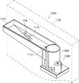
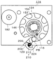
図1は、実施例の球体送り出し装置をパチンコ台に装着した斜視図である。
図2は、実施例の球体送り出し装置の平面図である。
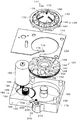
図3は、実施例の球体送り出し装置のヘッドを取り外した斜視図である
図4は、実施例の球体送り出し装置の分解斜視図である。
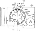
図5は、図2におけるA―A線断面図である。
図6は、実施例の球体送り出し装置の底面図である。
図7は、実施例の球体送り出し装置の第1回転ディスクを取り除いた平面図である。
図8は、実施例の球体送り出し装置の制動装置である電気ブレーキユニットの回路図である。
FIG. 1 is a perspective view of the ball delivery device of the embodiment mounted on a pachinko machine.
FIG. 2 is a plan view of the spherical body delivery device of the embodiment.
FIG. 3 is a perspective view in which the head of the spherical body delivery device of the embodiment is removed. FIG. 4 is an exploded perspective view of the spherical body delivery device of the embodiment.
5 is a cross-sectional view taken along line AA in FIG.
FIG. 6 is a bottom view of the sphere delivery device of the embodiment.
FIG. 7 is a plan view of the sphere delivery device of the embodiment with the first rotating disk removed.
FIG. 8 is a circuit diagram of an electric brake unit which is a braking device of the spherical body feeding device of the embodiment.
図1において、ゲーム機(パチンコ台)100の枠102の背面上部に球体PBの保留皿104が取り付けられている。
保留皿104はほぼ矩形であり、右側端部に球体送り出し装置106の一部を構成する上下方向に伸びる筒状のヘッド108が樹脂で一体に成形されている。
この樹脂は、静電気の帯電を防止するため導電性樹脂を採用し、アースすることが好ましい。
保留皿104の底110は、ヘッド108に向かって傾斜している。
したがって、保留皿104に保留された球体PBは自然にヘッド108に向かって転がる。
In FIG. 1, a retaining
The
This resin is preferably grounded by using a conductive resin in order to prevent electrostatic charge.
The
Therefore, the sphere PB held on the holding
ヘッド108は、バラ積み状態に球体PBを保留する機能を有している。
ヘッド108は、垂立している断面円形の筒状体である。
ヘッド108の上部の保留皿104に面した一部に、球体PBの直径の約三倍の幅を有する縦長のスリット112が形成されている。
この幅が狭い場合、球体PBのジャムが生じやすく、また、広すぎるとヘッド108内に大量の球体PBが転がり込み、回転ディスク114の回転抵抗が増加し、好ましくない。
保留皿104内の球体PBは、このスリット112を通過してヘッド108内に転がり込む。
ヘッド108の球体PBの保留量は、後述の回転ディスク114上に一回の最大払出数の約2倍に設定する。
少ない場合、最大数払出が連続して行われた場合、スリット112を介しての球体PBの補給が追いつかず、二回目の最大払出数が不足することがあり、多すぎる場合、回転ディスクの回転抵抗が大きくなり、大容量モータが必要になってコスト高になると共に消費エネルギーが多いためである。
The
The
A vertically long slit 112 having a width about three times the diameter of the sphere PB is formed in a part of the
If this width is narrow, jamming of the sphere PB tends to occur, and if it is too wide, a large amount of sphere PB rolls into the
The sphere PB in the
The holding amount of the sphere PB of the
In the case of a small number, if the maximum number of payouts is continuously performed, the replenishment of the sphere PB through the
次に球体送り出し装置106を説明する。
図2から図5に示すように、球体送り出し装置106は、前述のヘッド108、回転ディスク114、固定ガイド116、ベース118および回転ディスク114に隣接配置された出口120を含んでいる。
球体送り出し装置106は、ゲーム機のコントローラによって指示された所定数の球体PBを所定時間の間に次工程へ送り出す機能を有する。
Next, the
As shown in FIGS. 2 to 5, the spherical
The
次に回転ディスク114を説明する。
回転ディスク114は、ヘッド108から受け取った球体PBを一個ずつ保留部に受け取り、区分けする機能を有している。
図4に示すように、回転ディスク114は、上側の第1回転ディスク122と下側の第2回転ディスク124とで構成されている。
回転ディスク114は、後述の伝動手段を介して駆動源から回転駆動される。
Next, the
The
As shown in FIG. 4, the
The
図5に示すように、第1回転ディスク122は、その上面128の中央部が、回転軸線130を頂点とする錐形に形成された錐形部132と、その錐形部132の周囲に回転軸線130を中心とした水平部134が形成されている。
換言すれば、第1回転ディスク122の周縁部に回転軸線を中心とするリング状の水平部134が形成されている。
なお、錐形は四角錐や三角錐でもよいが、実施例に示す円錐形の場合、錐形の全周において均等な球体PBに対する案内効果を得られるので最も好ましい。
As shown in FIG. 5, the first
In other words, a ring-shaped
The pyramid may be a quadrangular pyramid or a triangular pyramid. However, the conical shape shown in the embodiment is most preferable because a uniform guiding effect on the sphere PB can be obtained in the entire circumference of the cone.
実施例において、水平部134は、錐形部132に形成した案内溝136である。
案内溝136は、平面において形成してもよい。
案内溝136は、回転軸線130を中心とするリング状に形成され、その断面において、球体PBの外周面の曲率の約3倍大きい曲率を有する。
したがって、案内溝136は、球体PBが位置することができ、球体PBの下部の約4分の1が落ち込む深さを有している。
In the embodiment, the
The
The
Therefore, the
第1開口部138である通孔140が、水平部134である案内溝136の底部において、所定の間隔で複数配置されている。
通孔140の前縁及び後縁の弧状部は、図5に示すように、球体PBの下側の左右周面に対しほぼ均等に位置している、換言すれば、左右均等の傾斜を有している。
第1開口部138は、実施例のように楕円形の孔にすることが、第1回転ディスク122の強度が大きいので好ましい。
しかし、後述の第2開口部142のように、側方が開口した溝状でもよい。
A plurality of through-
As shown in FIG. 5, the arcuate portions of the front edge and the rear edge of the through-
The
However, like the
案内溝136は、通孔140部に位置する球体PBの位置を安定させ、効率よく球体PBを通孔140に落下させる機能を有する。
第2回転ディスク124にも、第1開口部138に相対して第2開口部142が形成してある。
第2回転ディスク124は、図4及び図7に示すように、下部の円板部144及びその円板部144から上方に突出し、円板部144の中心部から周方向に延びる突条146を有する。
The
A
As shown in FIGS. 4 and 7, the second
円板部144の周縁には、被動歯車148が形成されている。
突条146は、通孔140の数と同数設けられ、所定の間隔で配置され、通孔140の間のリブ150の下方に配置される。
球体PBをスムーズに回転ディスク114の周方向に押し出すため、突条146は円板部144の周縁に近づくほど回転方向の後位に位置するよう湾曲形成することが好ましい。
A driven
The
In order to smoothly extrude the spherical body PB in the circumferential direction of the
したがって、円板部144の上面である載置部152と回転方向前後の突条146によって、第2回転ディスク124の周面側が開口した保持部154が所定の間隔で形成される。
第2回転ディスク124は、ベース118に形成したリング状のガイド溝156内に配置され、ガイド溝156の中心部において垂立する固定軸158にベアリング160を介して回転自在に取り付けられている。
Therefore, the holding
The second
第1回転ディスク122は、スクリュウ162によって第2回転ディスク124と同心に固定されて、一体化されている。
第1回転ディスク122の裏面には、突条146と同様形状であって、かつ、下方に突出する上側突条164が形成されている。
上側突条164の下端と突条146の上端との間は、所定の隙間166が形成されている。
The first
On the back surface of the first
A
したがって、第1開口部138と第2開口部142は、上下に重なって上下方向に伸びる楕円形の保持穴168を構成する。
保持穴168は、載置部152が底であって、突条146及び上側突条164とで回転方向前後を画定され、上部を第1回転ディスク122の周縁部170で囲われ、周面が開口している。
しかし、上側突条164及び回転ディスク122の周縁部170で囲わなくとも、球体PBを移動させる機能は発揮できる。
Therefore, the
The holding
However, the function of moving the sphere PB can be exhibited without being surrounded by the
載置部152と周縁部170の間隔は、球体PBの直径よりも僅かに大きく、保持穴168に落下した球体PBがそれらの間を通過できる。
周縁部170を設けない場合、球体PBの頂部が第1回転ディスク122の上面から突出しないように設定される。
この構成により、球体PBが、上面128上の球体PBによって保持穴168から押し出されないようにしている。
The interval between the mounting
When the
With this configuration, the sphere PB is prevented from being pushed out of the holding
上面128には、回転軸線130から放射状に等間隔にリブ172が形成され、ヘッド108内の球体PBを攪拌すると共に、上面128に沿って転げ落ちる球体PBを案内して案内溝136にスムーズに落下するようにしてある。
なお、第1回転ディスク122の厚みは、球体PBの直径の2から3倍に設定することができる。
通孔140内に複数の球体PBを保留可能にし、球体PBが通孔140内に常に保留されるようにすることにより、球体PBを連続的に払い出すためである。
The thickness of the first
This is because a plurality of spheres PB can be retained in the through
案内溝136を平面部に形成した場合、第1回転ディスク122の回転により、上面128上の球体PBは遠心力を受けるため、回転ディスク114の周縁部に移動するから、案内溝136に落下し、その後、通孔140に落下することができ、スムーズに球体PBが通孔140に落下する。
When the
第1回転ディスク122と第2回転ディスク124は、樹脂で製作することが好ましい。
複雑な形状を一体成形することにより、安価に製造できるからである。
この場合、第1回転ディスク122は、耐久性に優れるナイロン系の樹脂にし、第2回転ディスク124は機械的強度に優れる樹脂が適している。
結果として、回転ディスク114の耐久性が向上する。
The first
This is because it can be manufactured at low cost by integrally molding a complicated shape.
In this case, the first
As a result, the durability of the
しかし、第1回転ディスク122と第2回転ディスク124は、樹脂などにより一体成形することができる。
この場合、製造工程が短縮され、複雑な形状を精度良く安価に製造することができる。
通孔140の幅(図2において第1回転ディスク122の半径方向)は、球体PBの直径よりも僅かに大きく設定されている。
また、通孔140の長さは(第1回転ディスク122の周方向)、球体PBの直径の2倍以下の範囲で形成され、全体として長孔に形成されている。
However, the first
In this case, the manufacturing process is shortened, and a complicated shape can be manufactured accurately and inexpensively.
The width of the through hole 140 (in the radial direction of the first
Further, the length of the through hole 140 (circumferential direction of the first rotating disk 122) is formed in a range not more than twice the diameter of the sphere PB, and is formed as a long hole as a whole.
このように長孔にすることにより、回転ディスク114が高速で回転しても、球体PBの通孔140に落下可能な時間を長くして確実に落下させることができる。
長さを2倍以下にすることにより、複数の球体PBが通孔140内で重なることはあるが、出口120に同時に相対することがないので、2個同時に払い出されることがない。
By making such a long hole, even if the
By setting the length to 2 times or less, a plurality of spheres PB may overlap in the through-
図5に示すように、回転ディスク114はヘッド108のすぐ下方に位置し、その上面128のほぼ全面がヘッド108の下端開口199に相対している。詳述すると、複数の第1開口部138がヘッド108の下端開口199に相対している。
したがって、ヘッド108内の球体PBは同時に複数の第1開口138に落下することができる。
そして、球体PBは、保持穴168に保留される。
As shown in FIG. 5, the
Accordingly, the sphere PB in the
The spherical body PB is held in the holding
次に固定ガイド116を説明する。
固定ガイド116は、回転ディスク114と一体に移動している球体PBを回転ディスク114の周方向に案内する機能を有している。
ベース118の上面に、ほぼ円形のガイド孔173を有するガイドプレート174が固定されている。
ガイドプレート174は、ガイド穴173によって球体PBを案内するため、耐摩耗性のある材料、例えば、ステンレスで作ることができるが、耐摩耗性樹脂によって作っても良い。
Next, the fixed
The fixed
A
Since the
ガイドプレート174の一部がガイド孔173の中心部に向かって突出して固定ガイド116を構成している。
この固定ガイド116によって、ガイド孔173からほぼ接線方向に延びた後、周方向に延びる導出路176が形成される。
これにより、固定ガイド116は、図5に示すように隙間166に位置し、その先端は固定軸近傍の第1回転ディスク122と第2回転ディスク124の間のリング溝178に位置している。
A part of the
The fixed
As a result, the fixed
固定ガイド116の先端がリング溝178に配置されることにより、第1回転ディスク122と第2回転ディスク124とで支持することができ、片持ち支持されている固定ガイド116の振動を抑制することができる。
ガイド孔173の円径部は、回転軸線130と同心に配置され、ヘッド108の内方のほぼ延長上に位置している。
これにより、保持穴168内の球体PBがガイド孔172によって案内されて回転ディスク114と一体に移動することができる。
しかし、ガイド孔173の機能は、ガイド溝156によって代替え可能である。その場合、固定ガイド116は、単体で形成され、上記と同様に配置される。
The Rukoto tip of the fixed
Circle diameter of the
Thereby, the spherical body PB in the holding
However, the function of the
次に回転ディスク114の駆動装置180を説明する。
駆動装置180は、回転ディスク114を所定の速度で回転させる機能を有する。
駆動装置180は、本実施例において電動モーター182及び減速機構184を含んでいるが、同様の機能を有する他の装置に変更することができる。
Next, the driving
The
The
次に減速機構184を説明する。
被動歯車148は、ガイド溝156に隣接配置されたギヤ穴186にほぼ垂直に固定されたシャフト188に回転自在に支持された駆動ギヤ192と噛み合っている。
この駆動ギヤ192は、一体に形成された被動歯車190を介してガイドプレート174上面に固定された電動モータ182の出力軸(図示せず)に固定されたギヤ194と噛み合っている。
この構成により、回転ディスク114は、電動モータ182によって所定の速度で回転される。
Next, the
The driven
The
With this configuration, the
次に出口120を説明する。
出口120は、固定ガイド116によって回転ディスク114の周方向に案内された球体PBが突条146によって押し出される部位である。
出口120に連続して出口通路200がベース118に形成されている。
出口通路200は、断面矩形の溝状であって、図4に示すようにガイド溝156に対し周方向に伸びている。
出口通路200の底面202は、ガイド溝156に連続し、フラットである。
Next, the
The
An
The
The
次に球体PBの検出装置210を説明する。
この検出装置210は、出口120を通過した球体PBを検出する機能を有している。
したがって、同様の機能を有する他の装置に変更することができる。
実施例の検出装置210は、出口通路200においてガイド溝156に隣接して位置する受動体212、図6に示すようにベース118の裏面の凹部214に配置した受動体212を取り付けたレバー216、センサ218及びレバー216を図6において支軸220を中心に反時計方向に回動させるスプリング222を含んでいる。
受動体212は、耐久性を考慮し、ローラにすることが好ましい。
レバー216は、受動体212が固定ガイド116に近づくように付勢されている。
Next, the
The
Therefore, it can be changed to another device having the same function.
The
The
The
しかしながら、受動体212は、貫通する円弧孔224の端部に係止され、固定ガイド116と受動体212との間隔が球体PBの直径よりも小さい距離で静止されている。
レバー216を圧縮スプリングで付勢する場合、スプリング力のバラツキが少ないので、スプリング力の調整が必要なく、さらに、耐久性を有する。
レバー216の他端部は、図6の位置から時計方向に回動された場合、センサ218の検知領域に移動するよう配置されている。
換言すれば、受動体212が球体PBによって固定ガイド116から離れるように移動されたとき、センサ218は、検出信号を出力する。
However, the
When the
The other end of the
In other words, when the
この検出信号は、払い出した球体PBのカウントに用いられる。
センサ218は、塵埃の影響を受けない近接センサが好ましいが、光電センサ等他のセンサを使用することができる。
図5に示すように、ヘッド108の内方は、案内溝136の外縁に隣接している。
これにより、球体PBが案内溝136に速やかに落下するようにしている。
さらに、出口120の上方のヘッド108の内面に、膨出部226が形成されている。
この膨出部226と第1開口部138の対面する縁部228との距離は、球体PBの直径よりも僅かに小さく形成されている。
これにより、出口120直上において、保持穴168内の球体PBの上に球体PBが乗ることがないので、確実に1つの球体PBのみが払い出される。
This detection signal is used to count the paid out sphere PB.
The
As shown in FIG. 5, whichever of the
Thereby, the sphere PB is quickly dropped into the
Further, a bulging
The distance between the bulging
Thereby, since the sphere PB does not get on the sphere PB in the holding
次に回転ディスク114の制動装置230を説明する。
制動装置230は、図8に示すように、電動モータ182の給電回路232をショートさせることにより、電動モータ182に制動力を付与する電気ブレーキユニット234を用いることができる。
電気ブレーキユニット234は、電動モータ182の給電回路232において、モータ182と並列に接続されたスイッチングユニット236を含んでいる。
スイッチングユニット236は、本実施例ではスイッチ238であるが、同様の機能を有する他のスイッチング手段に変更することができる。
Next, the
As shown in FIG. 8, the
The
The
給電回路232には、ゲーム機の制御装置(図示せず)からの指令で開閉されるスイッチ240が直列に接続されている。
スイッチ240が閉じられた場合、給電回路232は、閉回路になり、モータ182が所定の方向に回転される。
このとき、スイッチ238は開のため、電気ブレーキユニット234は機能しない。
スイッチ240が開放され、スイッチ238が閉になった場合、電気ブレーキユニット234は閉回路になる。
The
When the
At this time, since the
When the
この状態において、慣性回転によりモータ182は発電機として機能し、電気ブレーキユニット234に電流が流れる。
電動モータ182は、閉状態の電気ブレーキユニット234によってショートされるため、発電機としての電動モータ182の負荷が最大になり、制動力が減速機構184を介して回転ディスク114に加わる。
結果として、回転ディスク114は、僅かな慣性回転量で停止する。
In this state, the
Since the
As a result, the
次に実施例の作用を説明する。
球体PBは、図示しない自動配給装置によって保留皿104に補給される。
保留皿104内の球体PBは、底110の傾斜によってヘッド108へ向かって転がり、スリット112を通過してヘッド108に達する。
ヘッド108に流入した球体PBは、ヘッド108にバラ積み状態で保留される。
最下の第1回転ディスク122に接触する球体PBは、上面128の斜面によって案内溝136へ重力により転がり落ちる傾向を有する。
Next, the operation of the embodiment will be described.
The sphere PB is supplied to the holding
The sphere PB in the
The sphere PB that has flowed into the
The sphere PB in contact with the lowermost first
しかし、第1回転ディスク122が静止している場合、球体PBは釣り合った状態で静止している。
払出指示に基づいて電動モータ182が回転した場合、球体PBの払い出しに伴って第1回転ディスク122上の球体PBは、自重及び上に載っている球体PBにより押し付けられて案内溝136に落下し、ついで第1開口部138に落下する。
However, when the first
When the
図5に示すように、ヘッド108の下端開口199は複数の第1開口部138に相対しているので、重力で落下するにも関わらず、球体PBは同時に複数の第1開口部138に落下出来る。
このため、第1回転ディスク122が高速回転しても第1開口部138には必ず球体PBが保留されているため、それら球体PBは歯抜けすることなく払い出すことができる。
したがって、球体PBの払出数は、実質的に重力の影響を受けることがない。
As shown in FIG. 5 , since the
For this reason, since the spheres PB are always held in the
Therefore, the payout number of the sphere PB is not substantially affected by gravity.
第1回転ディスク122の回転により、リブ172が一体に移動し、球体PBを突き上げる。
結果として、球体PBが攪拌され、第1開口部138に落下するので払出の効率が高まる。
したがって、保持穴168に球体PBが保留されない事態を防ぐことができるので、単位時間当たりの払出数を増加することができる。
As the first
As a result, the sphere PB is agitated and falls into the
Therefore, since the situation where the sphere PB is not held in the holding
球体PBは、高速度で移動しているので、第1開口部138において、その慣性により落下量が少ない場合がある。
その場合であっても、球体PBは、通孔140が十分に長いので、保持穴168に確実に落下する。
これにより、球体PBは、確実に保持穴168に移動する。
Since the sphere PB is moving at a high speed, the amount of fall may be small in the
Even in that case, the spherical body PB surely falls into the holding
Thereby, the spherical body PB moves to the holding
保持穴168に落下した球体PBは、図5に示すようにガイド孔172によってガイドされつつ突条146及び上側突条164によって押されるので、その下面を載置部152に支えられて回転ディスク114とともに移動する。
球体PBが固定ガイド116に達した場合、回転ディスク114と同方向の移動は固定ガイド116によって阻止されるので、固定ガイド116によって回転ディスク114の周方向に導出路176を案内され、出口120を通って出口通路200に払い出される。
The spherical body PB that has fallen into the holding
When the sphere PB reaches the fixed
球体PBは出口120を通過した直後、受動体212を押すので、レバー216の一端部がセンサ218に近接し、センサ218はカウント信号を出力する。
球体PBが通過した後、受動体212、したがってレバー216はスプリング222によって元の位置に戻されて、次の払出に備える。
このレバー216の復帰動によって、球体PBは払出口204から勢いよく払い出される。
Immediately after passing through the
After the sphere PB has passed, the
Due to the return movement of the
センサ218からの信号が所定数になった場合、換言すれば所定数の球体PBが払い出された場合、電動モータ182が停止され、電気ブレーキユニット234が作動して回転ディスク114は急速停止する。
したがって、回転ディスク114は急速停止されるので、球体PBの過払出を生じない。
さらに、ヘッド108内の球体PBが減少し、結果として最下の球体PBの上に他の球体PBが載っていない場合、通孔140における球体PBの落下量が少なく、球体PBの下側周面が通孔140の後縁と衝突して上方に跳ね上げられることがある。
When the signal from the
Therefore, since the
Further, when the sphere PB in the
この場合、球体PBの跳ね上がり方向は、ほぼ真上になる。
球体PBがほぼ真上に跳ね上がるのは、案内溝136のため、通孔140の後縁がほぼ水平面に形成される。
これによって、球体PBの下側左右周面が通孔140後縁とほぼ均等に接するためである。
跳ね上がった球体PBは、再び案内溝136に落下するので、次の通孔140に落下しやすい。
In this case, the upward direction of the sphere PB is almost directly above.
It is the
This is because the lower left and right peripheral surfaces of the sphere PB are in contact with the rear edge of the through
Since the sphere PB jumped up falls again into the
本発明は、ボール状の媒体を使用するゲーム機の払出装置を高速度で払い出す装置に採用することができる。 INDUSTRIAL APPLICABILITY The present invention can be applied to a game machine payout device that uses a ball-shaped medium at a high speed.
PB 球体
108 ヘッド
116 固定ガイド
120 出口
122 第1回転ディスク
124 第2回転ディスク
136 案内溝
138 第1開口部
140 通孔
142 第2開口部
146 突条
152 載置部
154 保持部
226 膨出部
228 相対縁
142
Claims (1)
前記ヘッド(108)の下方に位置し、上面(128)の中央部に回転軸線(130)を頂点とする錘形部(132)が形成され、当該錘形部(132)の周囲に前記回転軸線(130)を中心とするリング状であって、断面形状が前記球体(PB)の外周面曲率よりも大きな曲率を有する弧状の案内溝(136)が形成され、かつ、1つの球体(PB)が上面側から下面側に移動可能であって、前記球体(PB)の直径の二分の一以下の範囲で長孔に形成された縦向きの複数の第1開口部(138)を前記案内溝(136)の底部に有し、下面に前記第1開口部(138)の回転方向前後に配置した上側突条(164)を有する第1回転ディスク(122)、
前記第1回転ディスク(122)の下方に位置し、かつ、前記第1回転ディスク(122)と同軸で一体回転し、さらに、前記第1開口部(138)に相対する真下に形成した載置部及び当該載置部の回転方向前後に配置した突条(146)によって前記第1開口部(138)に連通すると共に横向きに形成された第2開口部(142)を有する第2回転ディスク(124)、
前記突条(146)と上側突条(164)との間には隙間(166)が形成され、
前記第1回転ディスク(122)と前記第2回転ディスク(124)との間の前記隙間(166)であって、かつ、前記第1開口部(138)及び第2開口部(142)に相対して位置し、前記第2回転ディスク(122)の周方向へ球体(PB)を案内する固定ガイド(116)、
前記固定ガイド(116)に沿って前記第1回転ディスク(122)の周方向に伸び、前記球体(PB)の直径よりも僅かに広い幅を有する溝状の出口通路(200)、
前記出口通路(200)の一側に配置され、前記出口通路(200)を狭める方向に付勢されると共に通過する球体(PB)によって移動される受動体(212)、
前記受動体(212)の所定の移動を検知し、払出球体(PB)のカウントのための検出信号を出力するセンサ(218)、
とを有する球体計数装置。 A cylindrical head (108) for holding a plurality of spheres (PB) in a stacked state,
A weight-shaped part (132) is formed at the center of the upper surface (128) and is located at the center of the upper surface (128). The weight-shaped part (132) is formed at the top of the head (108). An arc-shaped guide groove (136) having a ring shape centering on the axis (130) and having a curvature larger than the outer peripheral surface curvature of the sphere (PB) is formed, and one sphere (PB ) Is movable from the upper surface side to the lower surface side, and guides the plurality of vertical first openings ( 138 ) formed in the long holes within a range of ½ or less of the diameter of the sphere (PB). A first rotating disk (122) having an upper ridge (164) at the bottom of the groove (136) and disposed on the lower surface of the first opening ( 138 ) before and after the rotation direction;
A mounting located below the first rotating disk (122), rotating integrally with the first rotating disk (122) and coaxially, and formed directly below the first opening (138). And a second rotating disk (2) having a second opening ( 142 ) formed in a lateral direction and communicated with the first opening (138) by a ridge (146) disposed before and after the rotation direction of the mounting portion and the mounting portion. 124),
A gap (166) is formed between the ridge (146) and the upper ridge (164),
The gap (166) between the first rotating disk (122) and the second rotating disk (124) and relative to the first opening (138) and the second opening ( 142 ) A fixed guide (116) for guiding the sphere (PB) in the circumferential direction of the second rotating disk (122),
A groove-shaped outlet passage (200) extending in the circumferential direction of the first rotating disk (122) along the fixed guide (116) and having a width slightly wider than the diameter of the sphere (PB),
A passive body (212) disposed on one side of the outlet passage (200) and biased in a direction to narrow the outlet passage (200) and moved by a passing sphere (PB);
A sensor (218) for detecting a predetermined movement of the passive body (212) and outputting a detection signal for counting the payout ball (PB);
And a sphere counting device.
Priority Applications (1)
| Application Number | Priority Date | Filing Date | Title |
|---|---|---|---|
| JP2003396330A JP4635134B2 (en) | 2003-11-26 | 2003-11-26 | Sphere counting device |
Applications Claiming Priority (1)
| Application Number | Priority Date | Filing Date | Title |
|---|---|---|---|
| JP2003396330A JP4635134B2 (en) | 2003-11-26 | 2003-11-26 | Sphere counting device |
Publications (3)
| Publication Number | Publication Date |
|---|---|
| JP2005152372A JP2005152372A (en) | 2005-06-16 |
| JP2005152372A5 JP2005152372A5 (en) | 2007-01-18 |
| JP4635134B2 true JP4635134B2 (en) | 2011-02-16 |
Family
ID=34721842
Family Applications (1)
| Application Number | Title | Priority Date | Filing Date |
|---|---|---|---|
| JP2003396330A Expired - Lifetime JP4635134B2 (en) | 2003-11-26 | 2003-11-26 | Sphere counting device |
Country Status (1)
| Country | Link |
|---|---|
| JP (1) | JP4635134B2 (en) |
Family Cites Families (5)
| Publication number | Priority date | Publication date | Assignee | Title |
|---|---|---|---|---|
| JPS60227784A (en) * | 1984-04-27 | 1985-11-13 | 株式会社 ユニバ−サル | Premium ball discharge apparatus |
| JPH03682U (en) * | 1989-05-24 | 1991-01-08 | ||
| JPH065683U (en) * | 1991-02-12 | 1994-01-25 | 株式会社リール総販 | Ball ejecting device for amusement machines |
| JP3153873B2 (en) * | 1993-10-18 | 2001-04-09 | アルゼ株式会社 | Hopper equipment |
| JPH0857128A (en) * | 1994-08-24 | 1996-03-05 | Kyowa Giken Kk | Ball-sending device for ball game machines |
-
2003
- 2003-11-26 JP JP2003396330A patent/JP4635134B2/en not_active Expired - Lifetime
Also Published As
| Publication number | Publication date |
|---|---|
| JP2005152372A (en) | 2005-06-16 |
Similar Documents
| Publication | Publication Date | Title |
|---|---|---|
| EP0266021B1 (en) | Coin dispensing apparatus | |
| JPH07114658A (en) | Hopper device | |
| JP4941905B2 (en) | Sphere delivery device for gaming machine | |
| JP4635134B2 (en) | Sphere counting device | |
| CN100570648C (en) | Coin Hopper | |
| JP4505585B2 (en) | Sphere feeding device | |
| JP4047610B2 (en) | Medal paying device and medal dropping mechanism for medal paying device | |
| JP2744940B2 (en) | Spherical dispensing device | |
| JP4431670B2 (en) | Sphere feeding device | |
| JP4403242B2 (en) | Sphere feeding device | |
| US7775863B2 (en) | Coin dispending device and method for rapidly recycling coins | |
| JP4543183B2 (en) | Sphere feeding device | |
| JP4810676B2 (en) | Sphere feeding device | |
| US7497769B2 (en) | Coin hopper | |
| JP4665098B2 (en) | Sphere delivery device for gaming machine | |
| JP4849368B2 (en) | Coin dispenser | |
| JP2500697Y2 (en) | Coin dispenser | |
| JP4215120B2 (en) | Ball counting and dispensing device for pachinko machines | |
| JP6145604B2 (en) | Disc sorting apparatus, disc sorting assembly, and disc processing method using the same | |
| JP4132782B2 (en) | Pachinko machine ball dispenser | |
| JP4711738B2 (en) | Disc hopper with fraud prevention device | |
| JP5370737B2 (en) | Coin hopper | |
| WO2005038730A1 (en) | Coin dispensing apparatus | |
| JP6101910B2 (en) | Coin hopper | |
| JP4775810B2 (en) | Game machine equipped with a ball delivery device |
Legal Events
| Date | Code | Title | Description |
|---|---|---|---|
| A521 | Request for written amendment filed |
Free format text: JAPANESE INTERMEDIATE CODE: A523 Effective date: 20061124 |
|
| A621 | Written request for application examination |
Free format text: JAPANESE INTERMEDIATE CODE: A621 Effective date: 20061124 |
|
| A977 | Report on retrieval |
Free format text: JAPANESE INTERMEDIATE CODE: A971007 Effective date: 20091022 |
|
| A131 | Notification of reasons for refusal |
Free format text: JAPANESE INTERMEDIATE CODE: A131 Effective date: 20091104 |
|
| A521 | Request for written amendment filed |
Free format text: JAPANESE INTERMEDIATE CODE: A523 Effective date: 20091224 |
|
| A131 | Notification of reasons for refusal |
Free format text: JAPANESE INTERMEDIATE CODE: A131 Effective date: 20100624 |
|
| A521 | Request for written amendment filed |
Free format text: JAPANESE INTERMEDIATE CODE: A523 Effective date: 20100805 |
|
| A131 | Notification of reasons for refusal |
Free format text: JAPANESE INTERMEDIATE CODE: A131 Effective date: 20100901 |
|
| A521 | Request for written amendment filed |
Free format text: JAPANESE INTERMEDIATE CODE: A523 Effective date: 20100906 |
|
| TRDD | Decision of grant or rejection written | ||
| A01 | Written decision to grant a patent or to grant a registration (utility model) |
Free format text: JAPANESE INTERMEDIATE CODE: A01 Effective date: 20100928 |
|
| A01 | Written decision to grant a patent or to grant a registration (utility model) |
Free format text: JAPANESE INTERMEDIATE CODE: A01 |
|
| A61 | First payment of annual fees (during grant procedure) |
Free format text: JAPANESE INTERMEDIATE CODE: A61 Effective date: 20100929 |
|
| FPAY | Renewal fee payment (event date is renewal date of database) |
Free format text: PAYMENT UNTIL: 20131203 Year of fee payment: 3 |
|
| R150 | Certificate of patent or registration of utility model |
Free format text: JAPANESE INTERMEDIATE CODE: R150 Ref document number: 4635134 Country of ref document: JP Free format text: JAPANESE INTERMEDIATE CODE: R150 |
|
| R250 | Receipt of annual fees |
Free format text: JAPANESE INTERMEDIATE CODE: R250 |
|
| R250 | Receipt of annual fees |
Free format text: JAPANESE INTERMEDIATE CODE: R250 |
|
| R250 | Receipt of annual fees |
Free format text: JAPANESE INTERMEDIATE CODE: R250 |
|
| R250 | Receipt of annual fees |
Free format text: JAPANESE INTERMEDIATE CODE: R250 |
|
| R250 | Receipt of annual fees |
Free format text: JAPANESE INTERMEDIATE CODE: R250 |
|
| R250 | Receipt of annual fees |
Free format text: JAPANESE INTERMEDIATE CODE: R250 |
|
| R250 | Receipt of annual fees |
Free format text: JAPANESE INTERMEDIATE CODE: R250 |
|
| R250 | Receipt of annual fees |
Free format text: JAPANESE INTERMEDIATE CODE: R250 |
|
| R250 | Receipt of annual fees |
Free format text: JAPANESE INTERMEDIATE CODE: R250 |
|
| R250 | Receipt of annual fees |
Free format text: JAPANESE INTERMEDIATE CODE: R250 |
|
| EXPY | Cancellation because of completion of term |