EP0203779A2 - Coin dispenser - Google Patents
Coin dispenser Download PDFInfo
- Publication number
- EP0203779A2 EP0203779A2 EP86303868A EP86303868A EP0203779A2 EP 0203779 A2 EP0203779 A2 EP 0203779A2 EP 86303868 A EP86303868 A EP 86303868A EP 86303868 A EP86303868 A EP 86303868A EP 0203779 A2 EP0203779 A2 EP 0203779A2
- Authority
- EP
- European Patent Office
- Prior art keywords
- coins
- coin
- rotary disk
- bucket
- opening
- Prior art date
- Legal status (The legal status is an assumption and is not a legal conclusion. Google has not performed a legal analysis and makes no representation as to the accuracy of the status listed.)
- Withdrawn
Links
- 238000007599 discharging Methods 0.000 claims abstract description 9
- 230000000994 depressogenic effect Effects 0.000 description 2
- 238000003756 stirring Methods 0.000 description 2
- 230000000712 assembly Effects 0.000 description 1
- 238000000429 assembly Methods 0.000 description 1
- 238000010276 construction Methods 0.000 description 1
- 238000001514 detection method Methods 0.000 description 1
- 238000010586 diagram Methods 0.000 description 1
- 238000004519 manufacturing process Methods 0.000 description 1
- 238000012986 modification Methods 0.000 description 1
- 230000004048 modification Effects 0.000 description 1
- 238000009877 rendering Methods 0.000 description 1
Images


Classifications
-
- G—PHYSICS
- G07—CHECKING-DEVICES
- G07D—HANDLING OF COINS OR VALUABLE PAPERS, e.g. TESTING, SORTING BY DENOMINATIONS, COUNTING, DISPENSING, CHANGING OR DEPOSITING
- G07D9/00—Counting coins; Handling of coins not provided for in the other groups of this subclass
- G07D9/008—Feeding coins from bulk
Definitions
- the present invention relates to coin dispensers which are able to discharge coins at a high rate.
- This coin dispenser usually includes a motor driven rotary disk placed at an angle of, for example, about 60 degrees relative to a horizontal plane in a bucket which stores therein a number of coins to be discharged.
- This rotary disk is provided, on its surface, with a circular row of projections arranged at regular intervals for releasably holding the coins between them.
- the rotary disk faces the bottom of the bucket at its lower position and a coin passage communicating with the coin discharge outlet at its upper position.
- a circular row of coins held between the projections are carried by the rotary disk upwardly and discharged one by one into the coin passage and then into the coin discharge outlet.
- the rotary disk since' the rotary disk is inclined, at its lower position the rotary disk is directly subject to the weight of the coins stored in the bucket. As a result, it is hard to rotate the rotary disk at a high speed in order to discharge coins at a high rate.
- the coin discharge rate is, heretofore, up to four to five coins per second.
- the principal object of the present invention to provide a coin dispenser in which a coin discharging rotary disk can be rotated at a high speed so as to discharge coins at a high discharge rate.
- the coin discharging rotary disk can discharge coins at a high rate.
- Fig. 1 showing a slot machine with its front door opened, in which the apparatus for discharging coins according to an embodiment of the present invention is incorporated, there is provided, in a housing 2 with a hinged door 1, a set of reel assemblies 3 well known per se each of which includes a rotatable reel having an annular row of various symbols arranged thereon at regular intervals.
- the front door 1, which is usually closed, is adapted to allow symbols on each reel to be observed through reel windows 4 provided therein.
- a coin selector 6 is provided to receive coins inserted prior to the start of a game into a coin slot (not shown), through an exit 5 communicating with the coin slot and to then distinguish genuine coins from counterfeits therein.
- the coin selector 6 transfers the genuine coins into a main bucket 12 of a coin dispenser 10 through its outlet 7 and a chute 8 and the counterfeits to a coin receptacle 13 from a pay-out outlet through another outlet 9 and a chute 11.
- such a slot machine is played by inserting coins into the coin slot and pulling a start lever (not shown).
- the start lever When the player pulls the start lever, the reels start into rotation simultaneously. After each reel reaches a constant speed of rotation, each reel is controlled to stop on a random basis. When each reel is thus randomly stopped, the displayed symbols on each reel may be observed through the respective reel windows 4. At this time, a win decision is made based on the combinations of symbols stopping on the winning lines.
- the coin dispenser 10 is actuated to pay out as many coins as ccrrespond to that win, into the coin receptacle 13 form a pay-out outlet 15 formed in the chute 11, through a dispenser chute 14.
- a cover 16 which is opened to allow access to a coin reservoir 17.
- Coins from coin reservoir 17 pass into the main bucket 12 of the coin dispenser 10 through a chute 18 and its outlet 19.
- auxiliary bucket 22 In one side wall of the main bucket 12, there is an outlet defined by an opening 20 through which coins can flow out when the bucket 12 is filled up by more coins than its capacity as a result of continuous insersions of coins for repeated games. Coins flowing out are collected in an auxiliary bucket 22.
- the coin dispenser 10 includes a motor driven rotary disk 24 rotatably mounted in a base plate 22 attached horizontally to the housing 2 of the slot machine.
- a substanti- aly cylindrical guide wall'25 in such a way as to surround the rotary disk 24.
- the guide wall 25 has a part 25a which is depressed inwardly and is formed with an exit slit 26 at its bottom edge. This exit slit 26 is so formed as to allow a coin 30 placed horizontally to pass therethrough. It is permissible to provide a space having a distance less than half a diameter of the coin between the guide wall 25 and the periphery of the rotary disk 24.
- the bucket 12 Above the base plate 22, there is a funnel-shaped bucket 12 having an opening 28 at its bottom. Coins stored in the bucket 12 can fall down onto the rotary disk 24. As is seen in Fig. 3, the bucket 12 is formed with a collar at its bottom so as to render coins falling down as horizontal as possible. This collar serves to strive for a smooth flow of coins from the bucket 12 to the rotary disk 24.
- the rotary disk 24 is fixedly held between an upper holding plate 34 having a pole 34a and a bottom holding plate 33 having a sleeve which is firmly connected to an output shaft 32a of a gear box 32.
- the gear box 32 can serves to transmit the rotation of a motor 23 to output shaft 32a, 32b. This holding arrangement makes it easy to assemble the rotary disk 24 and to keep the same in a fixed plane.
- the shaft 34a which extends inside the bucket 12 passing through the opening 28, is provided with a control disk 35 rotatably mounted at its top. This control disk 35 is free from the rotation of the rotary disk 24 which is rotated by the motor 23 through the gear box 32.
- the elastic roller 38 may be conntacted with the surface of the rotary disk 24 when the elastic roller 38 is rotated at a proper speed relative to that of the rotary disk 24 so as not to cause any interference with each other. If desirable, it is permissible to place the elastic roller 38 outside of the periphery of the rotatry disk 24.
- a coin sensing means which comprises a sensing pin 40 positioned in the path of coins discharged by the elastic roller 38.
- the sensing pin 40 is provided on an arm 43 which is forced by a spring 42 to turn in the unticlockwise direction.
- the coin 30a (in Fig. 4) discharged by the elastic roller 38 strikes the sensing pin 40, turning the arm 43 in the clockwise direction against the force of the spring 42, and then reaches the chute 14.
- the turn of the arm 43 is detected by a photosensor 45 when a coin strikes the sensing pin 40, thereby coins 30a discharged by the elastic roller 38 can be counted.
- the sensing pin 40 at its bottom end is connected to an arm of a solenoid 47 which pulls the sensing pin 40 when energized and holds it so as to disable the arm 43 to turn.
- a win judging circuit 50 provides a win signal which in turn actuates a relay driving circuit 51 to cause a power source switch Sl for supplying power to the motor 23 to turn ON, rendering the motor 23 to start into rotation in a normal direction.
- the motor 23 rotates both of the shafts 32a, 32b through the gear box 32 so as to rotate the rotary disk 24 and the elastic roller 38 in the counterclockwise direction.
- the rotation cf the rotary disk 24 causes coins 30 supplied thereonto through the opening 28 of the bucket 12 to slide outwardly under the centrifugal force of the rotary disk 24.
- the margin of the coin 30 contacts with the guid wall 25, then the coin 30 is moved along the inner surface of the guide wall 25.
- the exit slit 26 is so dimensioned as to allow coins to pass therethrough one by one.
- the discharged coin 30a strikes the sensing pin 40 so as to turn the arm 43 in the clockwise direction against the spring 42.
- This turn of the arm 43 is detected by the photosensor 45.
- the photosensor 45 is adapted to produce pulse signals one for every detection by the arm 43, the number of coins discharged into the coin receptacle 13 can be known by counting the pulse signals by a counter 52.
- a win judgment circuit 50 causes a circuit 53 to set therein the number of coins to be paid out correspond to the win.
- a coincidence detecting circuit 54 produces a cc- incidence signal.
- a timer 55 holds its output signal at a high level so as to keep a relay actuating circuit 56 activated, causing motor control switches S2 to contact with contacts a from contacts b, respectively.
- the motor 23 rotates in the reverse direction, momentarily, making the rotary disk 24 and the roller 38 rotate in the clockwise direction so as to stop the discharge of coins, quickly. Therefore, no excess coins are discharged from the coin dispenser 10.
- the coincidence signal is also sent to a solenoid actuating circuit 57 so as to energize the solenoid 47, prohibitting the arm 43 from turning.
- a solenoid actuating circuit 57 so as to energize the solenoid 47, prohibitting the arm 43 from turning.
- the timer 55 is operated to hold its output at a low level, allowing the relay actuating circuit 51 to turn OFF so as to turn a power supply switch Sl OFF. Simultaneously, the relay actuating circuit 56 turns OFF, allowing the switches S2 to return to their initial possition, namely in contact with contacts b, respectively.
- the counter 52 and the coin pay-out number setting circuit 53 are reset to their initial situations.
- the contrcl disk 35 rotatably mounted on the shaft 34a projecting from the rotary disk 24 can sustain a large force from a large number of coins in the bucket 12 and thereby prevent the rotary disk 24 from being subject to a heavy loading, and that the control disk 35, which is rotatable independently from the shaft 34a, can allow the rotary disk 24 to rotate without lowering its speed of rotation even the control disk 35 is buried in a large amount of coins.
- Figs. 6 to 8 show the coin dispenser according to another embodiment of the present invention which is similar to that of the above described embodiment except in the construction of the control disk.
- a control disk assembly 55 fixedly mounted on bosses 12a by set screws.
- This control disk assembly 55 comprises a holding plate 56 fixed to the bucket 12 and a cone-shaped disk 57 fixedly mounted on the holding plate 56 by set screws.
- the control disk assembly 55 is provided in order not only to prevent the rotary disk zl from being directly subject to heavy weight from coins but also to prevent coins from remaining on the assembly. Therefore, is it is allowable that coins remain on the flat holding plate 36, the cone-shaped disk 57 can be omitted.
Abstract
Description
- The present invention relates to coin dispensers which are able to discharge coins at a high rate.
- As is well known in the art, automatic vending machines, money exchanging machines, coin or token-operated amusement machines such as slot machines, etc. have a coin or token. (hereinafter referred to as coins) dispenser therein which is adapted discharge coins into a pay-out outlet.
- This coin dispenser usually includes a motor driven rotary disk placed at an angle of, for example, about 60 degrees relative to a horizontal plane in a bucket which stores therein a number of coins to be discharged. This rotary disk is provided, on its surface, with a circular row of projections arranged at regular intervals for releasably holding the coins between them. The rotary disk faces the bottom of the bucket at its lower position and a coin passage communicating with the coin discharge outlet at its upper position. When the rotary disk is rotated, a circular row of coins held between the projections are carried by the rotary disk upwardly and discharged one by one into the coin passage and then into the coin discharge outlet.
- However, in the above-described coin dispenser, since' the rotary disk is inclined, at its lower position the rotary disk is directly subject to the weight of the coins stored in the bucket. As a result, it is hard to rotate the rotary disk at a high speed in order to discharge coins at a high rate. The coin discharge rate is, heretofore, up to four to five coins per second.
- It is, therefore, the principal object of the present invention to provide a coin dispenser in which a coin discharging rotary disk can be rotated at a high speed so as to discharge coins at a high discharge rate.
- According to the present invention there is provided
- a coin dispenser comprising:
- a bucket for storing a number of coins therein which has an opening at its bottom;
- a rotary disk driven by a motor for placing thereon a part of said coins supplied from said bucket through said opening, said rotary disk being adapted to rotate in a substantially horizontal plane and causing said coins placed thereon to slide outwardly with centrifugal force:
- control means disposed above said opening in said bucket for preventing said rotary disk from being directly subject to the weight of said coins remaining in said bucket; and
- guide means having an exit slit for causing coins which slide outwardly on said rotary disk to move along the inner wall thereof to said exit slit as a result of the rotation of said rotary disk , thereby discharging said coins one by one through said exit slit.
- According to a feature of the present invention, since the control means allows the coin discharge rotary disk to rotate a high speed, the coin discharging rotary disk can discharge coins at a high rate.
- The invention will be further described by way of non- limitative example with reference to the accompanying drawings, in which:-
- Figure 1 is a perspective view of the interior of a slot machine embodying the present invention;
- Figure 2 is a perspective view showing more particularly an embodiment of the coin dispenser in accordance with the present invention;
- Figure 3 is a cross sectional view of the coin dispenser of Figure 2;
- Figure 4 is a plan view of the coin dispenser of Figure 2;
- Figure 5 is a block diagram showing a control circuit applied to the coin dispenser of Figure 2;
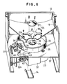
- Figure 6 is a perspective view similar to Figure 2, showing another embodiment of the coin dispenser;
- Figure 7 is a cross sectional view of the coin dispenser of Figure 6; and
- Figure 8 is a plan view of the coin dispenser of Figure 6.
- Referring now to Fig. 1 showing a slot machine with its front door opened, in which the apparatus for discharging coins according to an embodiment of the present invention is incorporated, there is provided, in a
housing 2 with a hinged door 1, a set of reel assemblies 3 well known per se each of which includes a rotatable reel having an annular row of various symbols arranged thereon at regular intervals. The front door 1, which is usually closed, is adapted to allow symbols on each reel to be observed throughreel windows 4 provided therein. - A
coin selector 6 is provided to receive coins inserted prior to the start of a game into a coin slot (not shown), through anexit 5 communicating with the coin slot and to then distinguish genuine coins from counterfeits therein. Thecoin selector 6 transfers the genuine coins into amain bucket 12 of acoin dispenser 10 through its outlet 7 and achute 8 and the counterfeits to acoin receptacle 13 from a pay-out outlet through anotheroutlet 9 and a chute 11. - As is well known, such a slot machine is played by inserting coins into the coin slot and pulling a start lever (not shown). When the player pulls the start lever, the reels start into rotation simultaneously. After each reel reaches a constant speed of rotation, each reel is controlled to stop on a random basis. When each reel is thus randomly stopped, the displayed symbols on each reel may be observed through the
respective reel windows 4. At this time, a win decision is made based on the combinations of symbols stopping on the winning lines. - As a result cf the win decision, if in fact there is a win, the
coin dispenser 10 is actuated to pay out as many coins as ccrrespond to that win, into thecoin receptacle 13 form a pay-outoutlet 15 formed in the chute 11, through adispenser chute 14. - At the top of the
housing 2, there is provided acover 16 which is opened to allow access to acoin reservoir 17. Coins fromcoin reservoir 17 pass into themain bucket 12 of thecoin dispenser 10 through achute 18 and itsoutlet 19. - In one side wall of the
main bucket 12, there is an outlet defined by anopening 20 through which coins can flow out when thebucket 12 is filled up by more coins than its capacity as a result of continuous insersions of coins for repeated games. Coins flowing out are collected in anauxiliary bucket 22. - As shown in Figs. 2 to 4, the
coin dispenser 10 includes a motor drivenrotary disk 24 rotatably mounted in abase plate 22 attached horizontally to thehousing 2 of the slot machine. On thebase plate 22, there is provided a substanti- aly cylindrical guide wall'25 in such a way as to surround therotary disk 24. As is apparent from Fig. 4, theguide wall 25 has apart 25a which is depressed inwardly and is formed with anexit slit 26 at its bottom edge. Thisexit slit 26 is so formed as to allow acoin 30 placed horizontally to pass therethrough. It is permissible to provide a space having a distance less than half a diameter of the coin between theguide wall 25 and the periphery of therotary disk 24. - Above the
base plate 22, there is a funnel-shaped bucket 12 having an opening 28 at its bottom. Coins stored in thebucket 12 can fall down onto therotary disk 24. As is seen in Fig. 3, thebucket 12 is formed with a collar at its bottom so as to render coins falling down as horizontal as possible. This collar serves to strive for a smooth flow of coins from thebucket 12 to therotary disk 24. - The
rotary disk 24 is fixedly held between anupper holding plate 34 having apole 34a and abottom holding plate 33 having a sleeve which is firmly connected to anoutput shaft 32a of agear box 32. Thegear box 32 can serves to transmit the rotation of amotor 23 to outputshaft rotary disk 24 and to keep the same in a fixed plane. - The
shaft 34a, which extends inside thebucket 12 passing through the opening 28, is provided with acontrol disk 35 rotatably mounted at its top. Thiscontrol disk 35 is free from the rotation of therotary disk 24 which is rotated by themotor 23 through thegear box 32. - Adjacent to the
exit slit 26 there is anelastic roller 38 made of, for example, rubber which is connected to theoutput shaft 32b of thegear box 32 through abelt 37 for rotation in order to discharge coins passing theexit slit 26 toward thechute 14. Although it is desirable to keep theelastic roller 38 apart from the surface of therotary disk 24, theelastic roller 38 may be conntacted with the surface of therotary disk 24 when theelastic roller 38 is rotated at a proper speed relative to that of therotary disk 24 so as not to cause any interference with each other. If desirable, it is permissible to place theelastic roller 38 outside of the periphery of therotatry disk 24. - Between the
elastic roller 38 and thechute 14 there is a coin sensing means which comprises asensing pin 40 positioned in the path of coins discharged by theelastic roller 38. The sensingpin 40 is provided on anarm 43 which is forced by aspring 42 to turn in the unticlockwise direction. Thecoin 30a (in Fig. 4) discharged by theelastic roller 38 strikes thesensing pin 40, turning thearm 43 in the clockwise direction against the force of thespring 42, and then reaches thechute 14. The turn of thearm 43 is detected by aphotosensor 45 when a coin strikes thesensing pin 40, therebycoins 30a discharged by theelastic roller 38 can be counted. - As is shown in Fig. 2, the
sensing pin 40 at its bottom end is connected to an arm of asolenoid 47 which pulls thesensing pin 40 when energized and holds it so as to disable thearm 43 to turn. - The operation of the
coin dispenser 10 will be explained hereunder in conjunction with a control circuit shown in Fig. 5. As a result of the win decision made based on the combinations of symbols displayed in thewindows 4, if in fact there is a win, awin judging circuit 50 provides a win signal which in turn actuates arelay driving circuit 51 to cause a power source switch Sl for supplying power to themotor 23 to turn ON, rendering themotor 23 to start into rotation in a normal direction. Themotor 23 rotates both of theshafts gear box 32 so as to rotate therotary disk 24 and theelastic roller 38 in the counterclockwise direction. The rotation cf therotary disk 24 causescoins 30 supplied thereonto through theopening 28 of thebucket 12 to slide outwardly under the centrifugal force of therotary disk 24. When the margin of thecoin 30 contacts with theguid wall 25, then thecoin 30 is moved along the inner surface of theguide wall 25. - The
coin 30, when reaches thedepressed part 25a of theguide wall 25, is discharged outside theguide walls 25 passing through theexit slot 26. At this time, the dischargedcoin 30 is forced by the rotatingelastic roller 38 to fly out toward thechute 14 and then is paid out into thecoin receptacle 13 passing through the chute 11 and the pay-outoutlet 15. The exit slit 26 is so dimensioned as to allow coins to pass therethrough one by one. - In the course from the
roller 38 to thechute 14, the dischargedcoin 30a (see Fig. 4) strikes thesensing pin 40 so as to turn thearm 43 in the clockwise direction against thespring 42. This turn of thearm 43 is detected by thephotosensor 45. During therotary disk 24 rotated, coins are discharged one by one in such a way as described above, and thearm 43 detects every discharge of a coin. Since thephotosensor 45 is adapted to produce pulse signals one for every detection by thearm 43, the number of coins discharged into thecoin receptacle 13 can be known by counting the pulse signals by acounter 52. - As shown in Fig. 5, a
win judgment circuit 50 causes acircuit 53 to set therein the number of coins to be paid out correspond to the win. When the accumulated count in thecounter 52 reaches the number set in the coinnumber setting circuit 53, acoincidence detecting circuit 54 produces a cc- incidence signal. For a predetermined interval of time from the production of the coincidence signal, atimer 55 holds its output signal at a high level so as to keep arelay actuating circuit 56 activated, causing motor control switches S2 to contact with contacts a from contacts b, respectively. As result, themotor 23 rotates in the reverse direction, momentarily, making therotary disk 24 and theroller 38 rotate in the clockwise direction so as to stop the discharge of coins, quickly. Therefore, no excess coins are discharged from thecoin dispenser 10. - On the other hand, the coincidence signal is also sent to a
solenoid actuating circuit 57 so as to energize thesolenoid 47, prohibitting thearm 43 from turning. As a result, coins, if they are discharged accidentally, strike the detectingpin 40 and rebounded therefrom, so that accidentally discharged coins are not paid out. It is noted in the event of using alternating-current motors as themotor 23, it is possible to stop the alternating-current motor quickly by supplying direct current thereto at the moment when therotary disk 24 is to be stopped. - After the predetermined interval of time has elapsed, the
timer 55 is operated to hold its output at a low level, allowing therelay actuating circuit 51 to turn OFF so as to turn a power supply switch Sl OFF. Simultaneously, therelay actuating circuit 56 turns OFF, allowing the switches S2 to return to their initial possition, namely in contact with contacts b, respectively. When the coin pay-out operation is completed, thecounter 52 and the coin pay-outnumber setting circuit 53 are reset to their initial situations. - In the above-described
coin dispenser 10, even if a large number of coins is stored in thebucket 12, it is possible to keep the coin discharge rate more than 15 to 16 coins per second. The reason is that thecontrcl disk 35 rotatably mounted on theshaft 34a projecting from therotary disk 24 can sustain a large force from a large number of coins in thebucket 12 and thereby prevent therotary disk 24 from being subject to a heavy loading, and that thecontrol disk 35, which is rotatable independently from theshaft 34a, can allow therotary disk 24 to rotate without lowering its speed of rotation even thecontrol disk 35 is buried in a large amount of coins. - Even if the bucket is filled to capacity with coins, coins advancing under the
control disk 35 are not subject to large forces. Consequently, it is possible to stir the coins using apin 36 projecting from theupper holding plate 34 so as to distribute the weight exerted onto therotary disk 24. As a result of stirring the coins, coins are prevented from getting stuck between thecontrol disk 35 and thebucket 12 around theopening 28. It is of cource permissible to provide two pins or more. - Figs. 6 to 8 show the coin dispenser according to another embodiment of the present invention which is similar to that of the above described embodiment except in the construction of the control disk.
- In Figs. 6 to 8, there is provided in the
bucket 12 acontrol disk assembly 55 fixedly mounted onbosses 12a by set screws. Thiscontrol disk assembly 55 comprises a holdingplate 56 fixed to thebucket 12 and a cone-shapeddisk 57 fixedly mounted on the holdingplate 56 by set screws. Thecontrol disk assembly 55 is provided in order not only to prevent the rotary disk zl from being directly subject to heavy weight from coins but also to prevent coins from remaining on the assembly. Therefore, is it is allowable that coins remain on theflat holding plate 36, the cone-shapeddisk 57 can be omitted. - The invention has been described with particular reference to preferred illustrative embodiments thereof, but it will be understood that variations and modifications can be effected within the scope of the invention as defined in the appended claims.
Claims (10)
Applications Claiming Priority (2)
| Application Number | Priority Date | Filing Date | Title |
|---|---|---|---|
| JP60108401A JPS61267188A (en) | 1985-05-22 | 1985-05-22 | Coin dispensor |
| JP108401/85 | 1985-05-22 |
Publications (2)
| Publication Number | Publication Date |
|---|---|
| EP0203779A2 true EP0203779A2 (en) | 1986-12-03 |
| EP0203779A3 EP0203779A3 (en) | 1987-09-02 |
Family
ID=14483820
Family Applications (1)
| Application Number | Title | Priority Date | Filing Date |
|---|---|---|---|
| EP86303868A Withdrawn EP0203779A3 (en) | 1985-05-22 | 1986-05-21 | Coin dispenser |
Country Status (4)
| Country | Link |
|---|---|
| EP (1) | EP0203779A3 (en) |
| JP (1) | JPS61267188A (en) |
| AU (1) | AU585983B2 (en) |
| ZA (1) | ZA863788B (en) |
Cited By (3)
| Publication number | Priority date | Publication date | Assignee | Title |
|---|---|---|---|---|
| EP0910051A3 (en) * | 1997-10-16 | 2000-10-18 | Aruze Co., Ltd. | Coin-sending device |
| KR100390924B1 (en) * | 2000-06-13 | 2003-07-10 | 주식회사 이티엠 | Rotary Type Automatic Coin Dispenser |
| EP1850295A1 (en) * | 2006-04-27 | 2007-10-31 | Asahi Seiko Co., Ltd. | Coin dispensing method for coin dispensing device and coin dispensing device, and coin recycling machine using the coin dispensing device |
Families Citing this family (2)
| Publication number | Priority date | Publication date | Assignee | Title |
|---|---|---|---|---|
| JPS6258392A (en) * | 1985-09-06 | 1987-03-14 | オムロン株式会社 | Coin discharger |
| JPH0542537Y2 (en) * | 1986-11-14 | 1993-10-26 |
Citations (4)
| Publication number | Priority date | Publication date | Assignee | Title |
|---|---|---|---|---|
| US793562A (en) * | 1904-04-27 | 1905-06-27 | William W Broga | Coin-separating machine. |
| US2109658A (en) * | 1932-11-02 | 1938-03-01 | Ambrose E Zierick | Coin sorting machine |
| GB2105508A (en) * | 1981-07-10 | 1983-03-23 | Chance Manufacturing Inc | Gaming machines and coin dispensers |
| DE3419268A1 (en) * | 1983-05-24 | 1984-11-29 | Ainsworth Nominees Pty. Ltd., Rosebery, New South Wales | COIN ISSUING DEVICE |
Family Cites Families (1)
| Publication number | Priority date | Publication date | Assignee | Title |
|---|---|---|---|---|
| JPS59191686A (en) * | 1983-04-14 | 1984-10-30 | ナリタ技研株式会社 | Coin feeder for coin counter |
-
1985
- 1985-05-22 JP JP60108401A patent/JPS61267188A/en active Pending
-
1986
- 1986-05-21 AU AU57646/86A patent/AU585983B2/en not_active Expired
- 1986-05-21 ZA ZA863788A patent/ZA863788B/en unknown
- 1986-05-21 EP EP86303868A patent/EP0203779A3/en not_active Withdrawn
Patent Citations (4)
| Publication number | Priority date | Publication date | Assignee | Title |
|---|---|---|---|---|
| US793562A (en) * | 1904-04-27 | 1905-06-27 | William W Broga | Coin-separating machine. |
| US2109658A (en) * | 1932-11-02 | 1938-03-01 | Ambrose E Zierick | Coin sorting machine |
| GB2105508A (en) * | 1981-07-10 | 1983-03-23 | Chance Manufacturing Inc | Gaming machines and coin dispensers |
| DE3419268A1 (en) * | 1983-05-24 | 1984-11-29 | Ainsworth Nominees Pty. Ltd., Rosebery, New South Wales | COIN ISSUING DEVICE |
Cited By (3)
| Publication number | Priority date | Publication date | Assignee | Title |
|---|---|---|---|---|
| EP0910051A3 (en) * | 1997-10-16 | 2000-10-18 | Aruze Co., Ltd. | Coin-sending device |
| KR100390924B1 (en) * | 2000-06-13 | 2003-07-10 | 주식회사 이티엠 | Rotary Type Automatic Coin Dispenser |
| EP1850295A1 (en) * | 2006-04-27 | 2007-10-31 | Asahi Seiko Co., Ltd. | Coin dispensing method for coin dispensing device and coin dispensing device, and coin recycling machine using the coin dispensing device |
Also Published As
| Publication number | Publication date |
|---|---|
| JPS61267188A (en) | 1986-11-26 |
| AU585983B2 (en) | 1989-06-29 |
| ZA863788B (en) | 1987-01-28 |
| AU5764686A (en) | 1986-12-04 |
| EP0203779A3 (en) | 1987-09-02 |
Similar Documents
| Publication | Publication Date | Title |
|---|---|---|
| US4753625A (en) | Coin pay-out apparatus | |
| US4441515A (en) | Gaming device including coin dispensing means | |
| US5673812A (en) | Automated golf ball dispenser | |
| US5098339A (en) | Coin feeding device | |
| EP0266021A2 (en) | Coin dispensing apparatus | |
| EP0223591A2 (en) | Coin dispenser | |
| EP0575136B1 (en) | Coin dispenser and coin pay-out method | |
| JP2708489B2 (en) | Slot machine | |
| EP0203779A2 (en) | Coin dispenser | |
| JPH0747056B2 (en) | Gaming ball delivery device for pattern type gaming machine | |
| JP3766130B2 (en) | Coin dispenser | |
| JP3213073B2 (en) | Ball game machine | |
| JP2001054614A (en) | Slot machine | |
| JPS6246393A (en) | Controller for coin dispensor | |
| JP2548952B2 (en) | Ball game machine | |
| JPS62126490A (en) | Coin dispenser | |
| JPS6130698Y2 (en) | ||
| JPH0621512Y2 (en) | Pachinko machine | |
| JPH0330931Y2 (en) | ||
| JP2753606B2 (en) | Ball rental equipment for gaming machines | |
| JPH0330932Y2 (en) | ||
| JP2579287B2 (en) | Ball game machine | |
| JP2525341B2 (en) | Ball game machine | |
| JPH07121309B2 (en) | Ball game machine | |
| JP2689067B2 (en) | Game equipment |
Legal Events
| Date | Code | Title | Description |
|---|---|---|---|
| PUAI | Public reference made under article 153(3) epc to a published international application that has entered the european phase |
Free format text: ORIGINAL CODE: 0009012 |
|
| AK | Designated contracting states |
Kind code of ref document: A2 Designated state(s): AT CH DE FR GB LI |
|
| PUAL | Search report despatched |
Free format text: ORIGINAL CODE: 0009013 |
|
| AK | Designated contracting states |
Kind code of ref document: A3 Designated state(s): AT CH DE FR GB LI |
|
| 17P | Request for examination filed |
Effective date: 19871023 |
|
| 17Q | First examination report despatched |
Effective date: 19891206 |
|
| STAA | Information on the status of an ep patent application or granted ep patent |
Free format text: STATUS: THE APPLICATION IS DEEMED TO BE WITHDRAWN |
|
| 18D | Application deemed to be withdrawn |
Effective date: 19900417 |
|
| RIN1 | Information on inventor provided before grant (corrected) |
Inventor name: OKADA, KAZUOC/O K. K. UNIVERSAL |