JP2005295735A - Electric connection box - Google Patents
Electric connection box Download PDFInfo
- Publication number
- JP2005295735A JP2005295735A JP2004109893A JP2004109893A JP2005295735A JP 2005295735 A JP2005295735 A JP 2005295735A JP 2004109893 A JP2004109893 A JP 2004109893A JP 2004109893 A JP2004109893 A JP 2004109893A JP 2005295735 A JP2005295735 A JP 2005295735A
- Authority
- JP
- Japan
- Prior art keywords
- module
- connector
- fuse
- relay
- case
- Prior art date
- Legal status (The legal status is an assumption and is not a legal conclusion. Google has not performed a legal analysis and makes no representation as to the accuracy of the status listed.)
- Granted
Links
- 239000004020 conductor Substances 0.000 claims description 14
- 230000002093 peripheral effect Effects 0.000 claims description 8
- 238000003466 welding Methods 0.000 description 6
- 230000013011 mating Effects 0.000 description 3
- 239000000758 substrate Substances 0.000 description 3
- 238000010586 diagram Methods 0.000 description 2
- 238000004519 manufacturing process Methods 0.000 description 2
- 238000005476 soldering Methods 0.000 description 2
- 238000007792 addition Methods 0.000 description 1
- 210000003127 knee Anatomy 0.000 description 1
- 239000002184 metal Substances 0.000 description 1
- 238000000034 method Methods 0.000 description 1
- 230000001737 promoting effect Effects 0.000 description 1
- 238000004080 punching Methods 0.000 description 1
Images


Classifications
-
- H—ELECTRICITY
- H05—ELECTRIC TECHNIQUES NOT OTHERWISE PROVIDED FOR
- H05K—PRINTED CIRCUITS; CASINGS OR CONSTRUCTIONAL DETAILS OF ELECTRIC APPARATUS; MANUFACTURE OF ASSEMBLAGES OF ELECTRICAL COMPONENTS
- H05K7/00—Constructional details common to different types of electric apparatus
- H05K7/02—Arrangements of circuit components or wiring on supporting structure
- H05K7/026—Multiple connections subassemblies
-
- H—ELECTRICITY
- H01—ELECTRIC ELEMENTS
- H01H—ELECTRIC SWITCHES; RELAYS; SELECTORS; EMERGENCY PROTECTIVE DEVICES
- H01H85/00—Protective devices in which the current flows through a part of fusible material and this current is interrupted by displacement of the fusible material when this current becomes excessive
- H01H85/02—Details
- H01H85/20—Bases for supporting the fuse; Separate parts thereof
- H01H2085/2075—Junction box, having holders integrated with several other holders in a particular wiring layout
- H01H2085/208—Junction box, having holders integrated with several other holders in a particular wiring layout specially adapted for vehicles
-
- H—ELECTRICITY
- H01—ELECTRIC ELEMENTS
- H01R—ELECTRICALLY-CONDUCTIVE CONNECTIONS; STRUCTURAL ASSOCIATIONS OF A PLURALITY OF MUTUALLY-INSULATED ELECTRICAL CONNECTING ELEMENTS; COUPLING DEVICES; CURRENT COLLECTORS
- H01R9/00—Structural associations of a plurality of mutually-insulated electrical connecting elements, e.g. terminal strips or terminal blocks; Terminals or binding posts mounted upon a base or in a case; Bases therefor
- H01R9/22—Bases, e.g. strip, block, panel
- H01R9/24—Terminal blocks
- H01R9/2458—Electrical interconnections between terminal blocks
Landscapes
- Engineering & Computer Science (AREA)
- Microelectronics & Electronic Packaging (AREA)
- Connection Or Junction Boxes (AREA)
Abstract
Description
本発明は、電気接続箱に関し、詳しくは、リレーモジュール、ヒューズモジュール、コネクタモジュールの配置位置を改良して、電気接続箱の低背化を図るものである。 The present invention relates to an electrical junction box, and more particularly, to improve the arrangement position of a relay module, a fuse module, and a connector module to reduce the height of the electrical junction box.
従来、自動車に搭載する電気接続箱として、本出願人は特開2000−92660号(特許文献1)等を提供している。前記特許文献1の電気接続箱1は、図7に示すように、アッパーケース2とロアケース3よりなるケース内部に、水平バスバー5A〜5Dを絶縁板4A〜4Dと交互に積層配置すると共に、該水平バスバー5A〜5Dの所要箇所を屈折してタブ5aを設け、該タブ5aをアッパーケース2とロアケース3の外面に突出させて設けたコネクタ収容部6、リレー収容部7、ヒューズ収容部8内に突出させている。
Conventionally, the present applicant has provided JP 2000-92660 (Patent Document 1) and the like as an electrical junction box to be mounted on an automobile. As shown in FIG. 7, the
しかしながら、特開2000−92660号で提供している電気接続箱1では、アッパーケース2とロアケース3の外面にコネクタ収容部6、リレー収容部7、ヒューズ収容部8等を上下方向に突出させて設け、これら収容部にコネクタ、リレー、ヒューズ等の電気部品を搭載しているため、これら電気部品が電気接続箱1の上下外面に突出され、電気接続箱1を低背化しにくい不具合があった。
However, in the
また、特開2002−27634号(特許文献2)において、図8に示すように、複数のリレー101を基板102に固定し、ケース内部に収容すると共に、電子基板103の導体と接続されたタブ104を側方に突出させたコネクタ収容部105内に突出させている電気接続箱100が提供されている。
Further, in Japanese Patent Laid-Open No. 2002-27634 (Patent Document 2), as shown in FIG. 8, a plurality of
しかしながら、特開2002−27634号で提供されている電気接続箱100でも、内部回路の電線wに接続されたタブ106は、アッパーケース107の外面に設けたコネクタ収容部108内に突出されており、内部回路の電線wと接続するコネクタはアッパーケース107の上方(図8中、下方)から嵌合させるため、前記電気接続箱1と同様に、電気接続箱の薄型化(低背化)することができない問題がある。
However, even in the
特に、自動車の前席の前方のインストルメントパネルの内部で、乗員の膝と対向する位置に電気接続箱が搭載される場合、該電気接続箱とパネル表面との間にスペースをあけて乗員が急ブレーキ等により前記パネルに衝突したときに、該パネルが十分に凹んで乗員への衝撃を低減させることが望まれている。しかしながら、インストルメントパネルの内部のスペースも限られているため、電気接続箱を薄型化してパネル表面との間に隙間を確保せざるを得ないが、前記したように、電気接続箱の薄型化が図れらていない問題がある。
本発明は前記問題に鑑みてなされたものであり、電気接続箱のケース上下面に突出させて設けていたヒューズ収容部、コネクタ収容部をケース側方に突出させて設けると共に、リレーをケース内部に収容することにより電気接続箱の低背化を図ることを課題としている。 The present invention has been made in view of the above problems, and provided with a fuse housing portion and a connector housing portion that protrude from the upper and lower surfaces of the case of the electrical connection box, and a relay that is provided inside the case. It is an object of the present invention to reduce the height of the electrical junction box by housing it in the container.
前記課題を解決するため、本発明は、ロアケースの上面に内部回路体を配置し、該内部回路体の上部で且つケース中央位置に、絶縁板上に複数のリレーを搭載したリレーモジュールを配置し、該リレーモジュールを囲む外周位置に、多数のヒューズを搭載するヒューズモジュールと、複数のコネクタ収容部を設けたコネクタモジュールを配置し、
前記リレーモジュール、ヒューズモジュール、コネクタモジュールの上方にアッパーケースを被せると共に、ヒューズモジュールおよびコネクタモジュールは前記ロアケースとアッパーケースの間の側面位置で外部に露出させて配置していることを特徴とする電気接続箱を提供している。
In order to solve the above problems, the present invention provides an internal circuit body disposed on the upper surface of the lower case, and a relay module in which a plurality of relays are mounted on an insulating plate is disposed above the internal circuit body and at the center of the case. A fuse module in which a large number of fuses are mounted and a connector module provided with a plurality of connector housing portions are arranged at an outer peripheral position surrounding the relay module;
An upper case is placed over the relay module, the fuse module, and the connector module, and the fuse module and the connector module are disposed so as to be exposed to the outside at a side surface position between the lower case and the upper case. A connection box is provided.
従来はケース外面に搭載されて電気接続箱の背を高くしているリレーを、本発明ではロアケースとアッパーケースに挟まれたケース中央内部に収容し、ヒューズモジュールとコネクタモジュールをリレーモジュールを囲む外周位置に配置した側面位置としている。このように、アッパーケースの上面及びロアケースの下面にリレー、ヒューズ及びコネクタの収容部を設けておらず、ケースの上下面から突出する電気部品を無くすことで電気接続箱の薄型化(低背化)している。
よって、電気接続箱を前記したように、乗員の前方位置のインストルメントパネル内部に配置すると、電気接続箱を薄型化したことにより、該電気接続箱とパネル表面との間にスペースを設けることができ、乗員が急ブレーキ等によりパネルに衝突したときにパネルを十分に凹ませて乗員への衝撃を低減して乗員を保護することができる。
Conventionally, a relay that is mounted on the outer surface of the case and has a tall electrical junction box is accommodated in the center of the case between the lower case and the upper case in the present invention, and the fuse module and the connector module are surrounded by the outer periphery of the relay module. The side position is set at the position. In this way, the relay case, fuse and connector housing are not provided on the upper case upper surface and lower case lower surface, and the electrical components that protrude from the upper and lower surfaces of the case are eliminated, making the electrical junction box thinner (lower profile). )doing.
Therefore, as described above, when the electrical connection box is disposed inside the instrument panel at the front position of the occupant, a space is provided between the electrical connection box and the panel surface by reducing the thickness of the electrical connection box. It is possible to protect the occupant by reducing the impact on the occupant by sufficiently denting the panel when the occupant collides with the panel due to sudden braking or the like.
前記リレーモジュールでは、前記絶縁板に固定したバスバーにリレーの端子を溶接して実装し、あるいはプリント基板上に実装して導体と半田付けしており、
該実装するリレーの搭載方向に対して、前記ヒューズモジュールのヒューズ取付方向およびコネクタモジュールのコネクタ収容部に嵌合するコネクタの取付方向を直交方向としている。
In the relay module, a relay terminal is welded and mounted on a bus bar fixed to the insulating plate, or mounted on a printed circuit board and soldered to a conductor.
With respect to the mounting direction of the relay to be mounted, the fuse mounting direction of the fuse module and the mounting direction of the connector fitted in the connector housing portion of the connector module are orthogonal.
本発明の電気接続箱では、ケース内部にリレーを収容しているため、プラグインタイプとせずに、前記のように絶縁板あるいは基板上に溶接した実装タイプとしている。
また、リレーモジュールを囲む外周位置に配置するヒューズおよびコネクタの取付方向をリレー搭載方向に対して直交方向とし、即ち、リレーをロアケースとアッパーケースとの間に上下方向に配置し、その外周に、ヒューズ、コネクタを左右横向き方向に配置すると、ヒューズ収容部、コネクタ収容部を上下複数段で配置することができ、電気接続箱の薄型化を促進しながら、ヒューズ、コネクタの接続箇所も充分にとることができる。
In the electrical junction box of the present invention, since the relay is accommodated inside the case, it is not a plug-in type but a mounting type welded onto an insulating plate or substrate as described above.
In addition, the mounting direction of the fuse and connector arranged at the outer peripheral position surrounding the relay module is set to a direction orthogonal to the relay mounting direction, that is, the relay is arranged in the vertical direction between the lower case and the upper case, When the fuse and connector are arranged in the horizontal direction, the fuse housing part and the connector housing part can be arranged in a plurality of upper and lower stages, and the connection portion of the fuse and connector is sufficiently secured while promoting the thinning of the electrical connection box. be able to.
前記リレーモジュールとアッパーケースとの間にECU(電子制御ユニット)を配置し、該ECUの実装部品と前記リレーモジュールのリレーを対向配置させ、前記ECUの導体と接続させた端子を突出させているECUコネクタ部をECU基板の周縁より突設し、該ECUコネクタ部を前記コネクタモジュールに連設していることが好ましい。 An ECU (Electronic Control Unit) is arranged between the relay module and the upper case, the mounting component of the ECU and the relay of the relay module are arranged to face each other, and a terminal connected to the conductor of the ECU is projected. It is preferable that the ECU connector part protrudes from the periphery of the ECU board, and the ECU connector part is connected to the connector module.
前記構成によれば、コネクタモジュールとヒューズモジュールの高さがリレーモジュールの高さより高い場合、リレーモジュール上にできるスペースを利用してECUの実装部品をリレーモジュールのリレーに対向させて配置している。このように、リレーモジュール上のスペースを有効に利用してECUの実装部品を配置しているため、電気接続箱が大型化して背が高くなってしまうこともない。 According to the said structure, when the height of a connector module and a fuse module is higher than the height of a relay module, the mounting component of ECU is arrange | positioned facing the relay of a relay module using the space made on a relay module. . As described above, since the mounting parts of the ECU are arranged by effectively using the space on the relay module, the electric junction box is not enlarged and tall.
前記ロアケースの上面に配置する内部回路体の導体は電線より形成し、該電線に接続する圧接端子を前記コネクタモジュールに設けているコネクタ収容部の端子孔より突設していることが好ましい。 It is preferable that the conductor of the internal circuit body arranged on the upper surface of the lower case is formed from an electric wire, and a press contact terminal connected to the electric wire is projected from a terminal hole of a connector housing portion provided in the connector module.
主としてリレーやヒューズの負荷側と接続する内部回路は中、小電流回路で良いため電線で内部回路を形成しており、電線を用いることにより、バスバーと比較して製作コストを安価にできると共に、回路変更や追加に容易に対応できる。 The internal circuit connected mainly to the load side of the relay or fuse may be a medium or small current circuit, so the internal circuit is formed with electric wires, and by using the electric wires, the manufacturing cost can be reduced compared to the bus bar, Can easily cope with circuit changes and additions.
前記ロアケースは略四角形状の底板の4隅より連結枠を突設し、略四角形状のアッパーケースと前記連結枠を介して連結し、前記ロアケースとアッパーケースとの間の一側面に前記ヒューズモジュールを配置すると共に他側面に前記コネクタモジュールを直交配置していることが好ましい。 The lower case has a connecting frame projecting from four corners of a substantially rectangular bottom plate, and is connected to the substantially rectangular upper case via the connecting frame, and the fuse module is mounted on one side surface between the lower case and the upper case. It is preferable that the connector module is disposed orthogonally on the other side surface.
前記構成によれば、偏平な略平板からなるロアケースとアッパーケースとの間には、4隅の連結枠を除く部分に、外面に露出させた側面部を形成でき、該側面にヒューズモジュールやコネクタモジュールを配置することができる。 According to the above configuration, the side surface portion exposed to the outer surface can be formed between the lower case and the upper case made of a flat and substantially flat plate, except for the connection frame at the four corners, and the fuse module and the connector can be formed on the side surface. Modules can be placed.
前記ヒューズモジュールの各ヒューズ収容部には、前記リレーモジュールに接続するバスバーの一端と前記内部回路体の電線に接続するヒューズ接続用端子の一端を突出させ、前記ヒューズ収容部に取り付けるヒューズと接続させていることが好ましい。
前記構成によれば、リレーモジュールと内部回路の電線との間にヒューズを容易に介設することができる。
One end of a bus bar connected to the relay module and one end of a fuse connection terminal connected to an electric wire of the internal circuit body are protruded from each fuse accommodating portion of the fuse module and connected to a fuse attached to the fuse accommodating portion. It is preferable.
According to the said structure, a fuse can be easily interposed between the relay module and the electric wire of an internal circuit.
前述したように、本発明によれば、リレーモジュールをケース内部の中央位置に配置すると共に、ヒューズモジュールとコネクタモジュールをリレーモジュールを囲む外周位置に配置し側面位置で外部に露出させ、アッパーケースの上面及びロアケースの下面にリレー、ヒューズ及びコネクタの収容部を設けず、ケースの上下面に突出する電気部品をなくしているため、電気接続箱の薄型化(低背化)することができる。 As described above, according to the present invention, the relay module is disposed at the center position inside the case, and the fuse module and the connector module are disposed at the outer peripheral position surrounding the relay module and exposed to the outside at the side surface position. Since the relay, fuse, and connector housings are not provided on the upper surface and the lower surface of the lower case, and the electrical components protruding from the upper and lower surfaces of the case are eliminated, the electrical connection box can be made thinner (low profile).
本発明の実施形態を図面を参照して説明する。
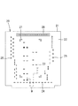
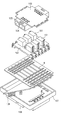
図1乃至図6は、本発明の実施形態を示し、電気接続箱10は、ロアケース11の上面側に内部回路体20を配置し、該内部回路体20の上部で且つケース中央位置にリレーモジュール30を配置し、該リレーモジュール30を囲む外周位置にヒューズモジュール40とコネクタモジュール50、51を配置し、リレーモジュール30の上方にECU(電子制御ユニット)60を配置し、さらにアッパーケース12を被せて形成している。
Embodiments of the present invention will be described with reference to the drawings.
1 to 6 show an embodiment of the present invention. In an
前記内部回路体20の導体は電線wとし、該電線wを下面開口のボックス形状のケース21の下面側に配線してケース21の内部に収容している。ケース21の上壁22には、図2に示すように、リレーモジュール30、ヒューズモジュール40及びコネクタモジュール50、51の配置位置近傍に複数の端子孔23、24、25を穿設しており、該端子孔23、24、25にリレーモジュール30のバスバー32、ヒューズモジュール40、コネクタモジュール50、51の各接続用端子43、54を貫通させてケース21内部の電線wと接続している。
また、ヒューズモジュール40及びコネクタモジュール50、51を配置しない周縁より雄コネクタ部26を突設し、ECU60の雌コネクタ部65と嵌合させて電線wをECUの導体と接続している。
内部回路体20のケース21の上壁22の中央には、上壁22の上面に載置するリレーモジュール30の絶縁板31の4隅を位置決め固定するためのL字状の位置決め突起27を所要の4箇所に突設している。
なお、内部回路体20の下面側には、絶縁板28を配置している。
The conductor of the
Further, a
At the center of the
An
前記リレーモジュール30は、内部回路体20の上部かつケース中央位置に配置されるものであり、絶縁板31の上面に導電性金属板を所要形状に打ち抜いて形成したバスバー32を固定しており、該バスバー32にリレー33の端子部を溶接してリレー33を絶縁板31に固定している。
なお、リレーモジュール30はプリント基板上にリレーを実装して、プリント基板の導体とリレーの端子部を半田付けすることにより形成してもよい。
The
The
リレーモジュール30には図3に示す入力側バスバー32aを介して電力が供給されている。該入力側バスバー32aは一端32a−1をコネクタモジュール50の電源入力部となるコネクタ収容部56内に突出させており、電源コネクタ内の端子と接続される。入力側バスバー32aの他端にはリレー33の入力端子部を溶接により接続している。
一方、リレーモジュール30の出力側は、ヒューズモジュール40のヒューズ44と接続する出力側バスバー32bは絶縁板31から側方に突出させて、先端の圧接タブ32b−1をヒューズモジュール40のヒューズ収容部41内に突出させてヒューズ44の入力側の端子部に圧接する一方、ヒューズ44と接続しない出力側バスバー32cは絶縁板31から下方に突出させて内部回路体20のケース21に設けた端子孔23を貫通させて内部回路の電線wに圧接している。
Electric power is supplied to the
On the other hand, on the output side of the
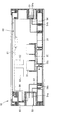
前記ヒューズモジュール40は、電気接続箱10の前側面(図3中の下側)に配置されるものであり、上下2段のヒューズ収容部41を水平方向に並設し、該ヒューズ収容部41をロアケース11とアッパーケース12の間の側面位置で外部に露出させている。上下のヒューズ収容部41はそれぞれ水平方向に位置をずらして千鳥配置としている。
The
ヒューズ収容部41に収容するヒューズ44の入力側の端子部と接続するバスバー42は、一端に圧接タブ42aを設けてヒューズ44の端子部に圧接する一方、他端の接続部42bを電気接続箱10の右側面に配置するコネクタモジュール50側に突出させて、該接続部42bを前記リレーモジュール30の入力側バスバー32aから分岐した接続部32a−2に抵抗溶接により接続し、溶接部45を形成している。よって、コネクタモジュール50の電源入力部となるコネクタ収容部56に電源コネクタを嵌合すると、リレーモジュール30と共にヒューズモジュール40にも電力が供給される。また、入力側の端子を前記バスバー42に接続しないヒューズ44は、リレーモジュール30から突出させた前記出力側バスバー32bの圧接タブ32b−1に入力側の端子部を接続している。
ヒューズ44の出力側の端子部には、図4に示すように、両端に圧接部を設けたL字状のヒューズ接続用端子43を接続しており、一端の圧接部43aをヒューズ収容部41内に突出させてヒューズ44の端子部に圧接する一方、他端側を下方に折り曲げて内部回路体20のケース21に設けた端子孔24に貫通させて他端の圧接部43bを電線wに圧接している。
The
As shown in FIG. 4, an L-shaped
コネクタモジュール50、51は、それぞれ電気接続箱10の右側面、左側面に配置するものであり、コネクタモジュール50、51にそれぞれ設けた複数のコネクタ収容部52、53をロアケース11とアッパーケース12の間の側面位置で外部に露出させている。なお、右側面に配置するコネクタモジュール50には、電源入力部となるコネクタ収容部56を設けて、側面位置で外部に露出させている。
また、コネクタモジュール50の上面にはECU60のECUコネクタ部63を嵌合する凹部55を設けている。
The
Further, a
コネクタ収容部52、53に嵌合する相手方コネクタ内の端子と接続する接続用端子54は、すべてL字状とし、一端を雄タブ54aとしてコネクタ収容部52、53内に突出させて相手方コネクタ内の端子と接続する一方、他端側を下方に屈折させて延在させ、内部回路体20のケース21に設けた端子孔25に貫通させて先端の圧接部54bを内部回路の電線wに圧接している。
The
図6は、内部回路体20、リレーモジュール30、ヒューズモジュール40、コネクタモジュール50、51により形成される回路図を示す。負荷側へ電力を供給する電源回路70は電源入力部からリレーモジュール30、ヒューズモジュール40及び内部回路体20を介してコネクタモジュール50、51に接続されている。電源回路70を制御する制御回路71は、電源入力部からリレーモジュール30及び内部回路体20を介してコネクタモジュール50、51に接続されている。また、他の回路72は、リレーモジュール30のリレー33を介さずに電源入力部に溶接部45で接続し、直接ヒューズモジュール40及び内部回路体20を介してコネクタモジュール50、51に接続している。
FIG. 6 shows a circuit diagram formed by the
前記ECU60には、図5に示すように、ECU基板61の下面側の導体(図示せず)に複数の電子部品(実装部品)62を半田付けにより接続し、該電子部品62をECU60の下方に配置しているリレーモジュール30のリレー33と対向配置している。
電気接続箱10の後面側には、ECU基板61の下面に周縁に沿って雌コネクタ部65を突設し、内部回路体20の雄コネクタ部26と嵌合させて、各コネクタ内の端子同士を接続し、内部回路の電線wとECU60の導体とを接続し、ECU60へ電力を供給している。
また、ECU基板60の周縁よりECUコネクタ部63を突設し、該ECUコネクタ部63をコネクタモジュール50の凹部55に嵌合させて連設している。ECUコネクタ部63には、一端をECU60の導体と接続させた接続用端子64の他端を突出させており、ECUコネクタ部63に嵌合する相手方コネクタ内の端子と接続される。
As shown in FIG. 5, a plurality of electronic components (mounting components) 62 are connected to the
On the rear surface side of the
Further, an
前記ロアケース11は略四角形状の底板の4隅より連結枠13を突設し、略四角形状のアッパーケース12と連結枠13を介して連結し、ロアケース11とアッパーケース12との間の前面側にヒューズモジュール40を配置すると共に左右側面にコネクタモジュール50、51を直交配置している。また、絶縁板31上に搭載する多数のリレー33を上方から搭載するのに対して、ヒューズモジュール40のヒューズ取付方向およびコネクタモジュール50、51のコネクタ収容部に嵌合するコネクタの取付方向を側方からとして直交方向としている
前記連結枠13はL字状とし、両端に各モジュールの両側をスライドさせてガイドするガイド溝14を設けている。
The
次に、電気接続箱10の製造方法について説明する。
先ず、ロアケース11内に下方から絶縁板28と内部回路体20を収容する。
次いで、リレーモジュール30の入力側バスバー32aの一端32a−1をコネクタモジュール50のコネクタ収容部56内に突出させると共に、出力側バスバー32bの圧接タブ32b−1をヒューズモジュール40のヒューズ収容部41内に突出させ、入力側バスバー32aの接続部32a−2とヒューズモジュール40のバスバー42の接続部42bを重ねて抵抗溶接により接続する。このようにして一体となったリレーモジュール30、ヒューズモジュール40、コネクタモジュール50とコネクタモジュール51を内部回路体20の上部に配置する。このとき、各モジュールの接続用端子やバスバーの圧接タブを内部回路体20のケース21の端子孔に貫通させて内部回路を構成する電線wに圧接している。
次いで、これらモジュールの上部にECUを配置し、雌コネクタ部65を内部回路体20の雄コネクタ部26と嵌合させて、内部回路の電線wとECU60の導体とを接続している。また、ECUコネクタ部63をコネクタモジュール50の凹部55に嵌合させている。
最後に、アッパーケース12を被せ、連結枠13を介してロアケース11と連結している。
Next, a method for manufacturing the
First, the insulating
Next, one
Next, the ECU is arranged on the upper part of these modules, and the
Finally, the
前記構成によれば、リレーモジュール30をケース内部の中央位置に配置すると共に、ヒューズモジュール40とコネクタモジュール50、51をリレーモジュール30を囲む外周位置に配置し側面位置で外部に露出させているため、アッパーケース12の上面及びロアケース11の下面にリレー、ヒューズ及びコネクタの収容部を設けておらず、ケースの上下面に突出する電気部品をなくすことができ、電気接続箱10を低背化することができる。
特に、前記電気接続箱10を自動車の乗員の前方位置に配置する場合には、電気接続箱10を薄型化(低背化)したことにより、パネルと電気接続箱10との間にスペースを設けることができるため、乗員が急ブレーキ等によりパネルに衝突したときにパネルを十分に凹ませて乗員への衝撃を低減して乗員を保護することができる。また、電気接続箱10を乗員に触れない位置に搭載することで、乗員が電気接続箱に衝突するのを防止して乗員を保護することができる。
According to the above configuration, the
In particular, when the
10 電気接続箱
11 ロアケース
12 アッパーケース
20 内部回路体
30 リレーモジュール
33 リレー
40 ヒューズモジュール
50、51 コネクタモジュール
60 ECU
w 電線
DESCRIPTION OF
w Electric wire
Claims (6)
前記リレーモジュール、ヒューズモジュール、コネクタモジュールの上方にアッパーケースを被せると共に、ヒューズモジュールおよびコネクタモジュールは前記ロアケースとアッパーケースの間の側面位置で外部に露出させて配置していることを特徴とする電気接続箱。 An internal circuit body is disposed on the upper surface of the lower case, a relay module having a plurality of relays mounted on an insulating plate is disposed at the upper center of the internal circuit body and at the center of the case, and a large number of outer peripheral positions surrounding the relay module are provided. A fuse module with a plurality of fuses and a connector module provided with a plurality of connector housing portions,
An upper case is placed over the relay module, the fuse module, and the connector module, and the fuse module and the connector module are disposed so as to be exposed to the outside at a side surface position between the lower case and the upper case. Connection box.
該実装するリレーの搭載方向に対して、前記ヒューズモジュールのヒューズ取付方向およびコネクタモジュールのコネクタ収容部に嵌合するコネクタの取付方向を直交方向としている請求項1に記載の電気接続箱。 In the relay module, a relay terminal is welded and mounted on a bus bar fixed to the insulating plate, or mounted on a printed circuit board and soldered to a conductor.
The electrical connection box according to claim 1, wherein a mounting direction of the relay to be mounted is orthogonal to a mounting direction of the fuse module and a mounting direction of the connector fitted in the connector housing portion of the connector module.
Priority Applications (4)
| Application Number | Priority Date | Filing Date | Title |
|---|---|---|---|
| JP2004109893A JP4254601B2 (en) | 2004-04-02 | 2004-04-02 | Electrical junction box |
| DE102005013511.0A DE102005013511B4 (en) | 2004-04-01 | 2005-03-23 | Electrical connection box |
| DE200510013513 DE102005013513A1 (en) | 2004-04-01 | 2005-03-23 | Relay for automotive electrical connector box, has terminals to which leads of lead-type resistor are connected when relay is to be connected to circuit requiring resistor |
| US11/092,710 US7252519B2 (en) | 2004-04-02 | 2005-03-30 | Electrical connector box |
Applications Claiming Priority (1)
| Application Number | Priority Date | Filing Date | Title |
|---|---|---|---|
| JP2004109893A JP4254601B2 (en) | 2004-04-02 | 2004-04-02 | Electrical junction box |
Publications (2)
| Publication Number | Publication Date |
|---|---|
| JP2005295735A true JP2005295735A (en) | 2005-10-20 |
| JP4254601B2 JP4254601B2 (en) | 2009-04-15 |
Family
ID=35054955
Family Applications (1)
| Application Number | Title | Priority Date | Filing Date |
|---|---|---|---|
| JP2004109893A Expired - Fee Related JP4254601B2 (en) | 2004-04-01 | 2004-04-02 | Electrical junction box |
Country Status (2)
| Country | Link |
|---|---|
| US (1) | US7252519B2 (en) |
| JP (1) | JP4254601B2 (en) |
Cited By (12)
| Publication number | Priority date | Publication date | Assignee | Title |
|---|---|---|---|---|
| JP2007209145A (en) * | 2006-02-02 | 2007-08-16 | Sumitomo Wiring Syst Ltd | Electrical connection box for vehicle |
| JP2007244112A (en) * | 2006-03-09 | 2007-09-20 | Fujikura Ltd | Electrical junction box for automobiles |
| JP2008022687A (en) * | 2006-07-14 | 2008-01-31 | Furukawa Electric Co Ltd:The | Electrical connection unit and electrical connection box |
| JP2008079361A (en) * | 2006-09-19 | 2008-04-03 | Yazaki Corp | Electrical junction box |
| JP2008301684A (en) * | 2007-06-04 | 2008-12-11 | Toyota Motor Corp | Electrical equipment and method for manufacturing the same |
| JP2012039678A (en) * | 2010-08-03 | 2012-02-23 | Fuji Electric Co Ltd | Inverter device |
| KR200463442Y1 (en) | 2009-12-31 | 2012-11-05 | 엘에스산전 주식회사 | Electric power controller for a hybrid car |
| KR101241798B1 (en) | 2009-06-26 | 2013-03-14 | 엘에스산전 주식회사 | Electric power controller for a hybrid car |
| KR101529067B1 (en) * | 2009-06-29 | 2015-06-16 | 한국단자공업 주식회사 | Power connection box |
| KR101561045B1 (en) | 2009-06-29 | 2015-10-16 | 한국단자공업 주식회사 | Power relay box |
| US9469205B2 (en) | 2014-09-25 | 2016-10-18 | Hyundai Motor Company | Female connector of high voltage junction box and method for assembling the same |
| KR20210103079A (en) * | 2020-02-13 | 2021-08-23 | 한국단자공업 주식회사 | connector block |
Families Citing this family (8)
| Publication number | Priority date | Publication date | Assignee | Title |
|---|---|---|---|---|
| JP4821567B2 (en) * | 2006-11-08 | 2011-11-24 | 住友電装株式会社 | Printed circuit board with fuse housing and electric junction box for automobile |
| JP4453726B2 (en) * | 2007-07-20 | 2010-04-21 | 住友電装株式会社 | Automotive junction box |
| TWM391225U (en) * | 2010-04-27 | 2010-10-21 | Hon Hai Prec Ind Co Ltd | Power distribution unit |
| JP5651079B2 (en) * | 2011-07-21 | 2015-01-07 | 矢崎総業株式会社 | Battery pack controller |
| US8913371B2 (en) * | 2012-10-26 | 2014-12-16 | Sumitomo Wiring Systems, Ltd. | Automotive fuse and relay block assembly |
| US9843148B2 (en) * | 2013-07-19 | 2017-12-12 | Foxconn Interconnect Technology Limited | Flippable electrical connector |
| JP7558492B2 (en) * | 2021-06-16 | 2024-10-01 | 株式会社オートネットワーク技術研究所 | Electrical Junction Box |
| CN113891609B (en) * | 2021-10-22 | 2022-05-24 | 安徽江淮汽车集团股份有限公司 | Expandable car electrical box |
Family Cites Families (8)
| Publication number | Priority date | Publication date | Assignee | Title |
|---|---|---|---|---|
| JP3336971B2 (en) | 1998-09-09 | 2002-10-21 | 住友電装株式会社 | Automotive electrical junction box |
| JP2000285988A (en) | 1999-04-01 | 2000-10-13 | Yazaki Corp | Connection structure between lead and busbar |
| JP2002027634A (en) | 2000-07-03 | 2002-01-25 | Yazaki Corp | Wiring board connection structure |
| JP2002084630A (en) | 2000-09-07 | 2002-03-22 | Sumitomo Wiring Syst Ltd | Electrical junction box for high voltage |
| DE60125008T2 (en) * | 2000-10-26 | 2007-07-05 | Sumitomo Wiring Systems, Ltd., Yokkaichi | Electric motor vehicle junction box |
| JP4161831B2 (en) * | 2003-07-15 | 2008-10-08 | 住友電装株式会社 | Electrical junction box |
| DE10334629B3 (en) * | 2003-07-29 | 2005-04-07 | Siemens Ag | Circuit module and method for its production |
| JP4254600B2 (en) * | 2004-04-01 | 2009-04-15 | 住友電装株式会社 | Electrical junction box |
-
2004
- 2004-04-02 JP JP2004109893A patent/JP4254601B2/en not_active Expired - Fee Related
-
2005
- 2005-03-30 US US11/092,710 patent/US7252519B2/en not_active Expired - Fee Related
Cited By (13)
| Publication number | Priority date | Publication date | Assignee | Title |
|---|---|---|---|---|
| JP2007209145A (en) * | 2006-02-02 | 2007-08-16 | Sumitomo Wiring Syst Ltd | Electrical connection box for vehicle |
| JP2007244112A (en) * | 2006-03-09 | 2007-09-20 | Fujikura Ltd | Electrical junction box for automobiles |
| JP2008022687A (en) * | 2006-07-14 | 2008-01-31 | Furukawa Electric Co Ltd:The | Electrical connection unit and electrical connection box |
| JP2008079361A (en) * | 2006-09-19 | 2008-04-03 | Yazaki Corp | Electrical junction box |
| JP2008301684A (en) * | 2007-06-04 | 2008-12-11 | Toyota Motor Corp | Electrical equipment and method for manufacturing the same |
| KR101241798B1 (en) | 2009-06-26 | 2013-03-14 | 엘에스산전 주식회사 | Electric power controller for a hybrid car |
| KR101561045B1 (en) | 2009-06-29 | 2015-10-16 | 한국단자공업 주식회사 | Power relay box |
| KR101529067B1 (en) * | 2009-06-29 | 2015-06-16 | 한국단자공업 주식회사 | Power connection box |
| KR200463442Y1 (en) | 2009-12-31 | 2012-11-05 | 엘에스산전 주식회사 | Electric power controller for a hybrid car |
| JP2012039678A (en) * | 2010-08-03 | 2012-02-23 | Fuji Electric Co Ltd | Inverter device |
| US9469205B2 (en) | 2014-09-25 | 2016-10-18 | Hyundai Motor Company | Female connector of high voltage junction box and method for assembling the same |
| KR20210103079A (en) * | 2020-02-13 | 2021-08-23 | 한국단자공업 주식회사 | connector block |
| KR102743036B1 (en) * | 2020-02-13 | 2024-12-16 | 한국단자공업 주식회사 | connector block |
Also Published As
| Publication number | Publication date |
|---|---|
| US20050221640A1 (en) | 2005-10-06 |
| US7252519B2 (en) | 2007-08-07 |
| JP4254601B2 (en) | 2009-04-15 |
Similar Documents
| Publication | Publication Date | Title |
|---|---|---|
| JP4254601B2 (en) | Electrical junction box | |
| JP4254600B2 (en) | Electrical junction box | |
| JP2000092661A (en) | Electrical junction box | |
| JP2006187050A (en) | Junction block | |
| JP3879750B2 (en) | Electrical junction box | |
| JP4424042B2 (en) | Automotive relays and electrical junction boxes | |
| JP4868928B2 (en) | Junction block | |
| JP2005210804A (en) | Relay arrangement structure | |
| JP2000092659A (en) | Electrical junction box | |
| JP4234687B2 (en) | Electrical junction box for automobiles | |
| JPH11191914A (en) | Electrical junction box | |
| JP4396703B2 (en) | Relay connector | |
| JP3678138B2 (en) | Junction box | |
| JP4728776B2 (en) | Circuit board with bus bar | |
| JP4728873B2 (en) | Wiring board unit | |
| JP6537100B2 (en) | Multi-stage substrate connection structure and electrical connection box | |
| JP2007227169A (en) | Busbar and electrical junction box | |
| JP3747777B2 (en) | Junction box | |
| JP2003079027A (en) | Junction box | |
| JP2001309526A (en) | Connecting structure for internal circuit of junction box to relay | |
| JP5403360B2 (en) | Electrical junction box | |
| JP5859762B2 (en) | Busbar and board connection structure and electrical junction box | |
| JP2001309525A (en) | Connecting structure for internal circuit of junction box to relay | |
| JP2008206377A (en) | Electrical junction box for automobile | |
| JP2011061104A (en) | Board device |
Legal Events
| Date | Code | Title | Description |
|---|---|---|---|
| A621 | Written request for application examination |
Free format text: JAPANESE INTERMEDIATE CODE: A621 Effective date: 20060616 |
|
| A131 | Notification of reasons for refusal |
Free format text: JAPANESE INTERMEDIATE CODE: A131 Effective date: 20080902 |
|
| A521 | Written amendment |
Free format text: JAPANESE INTERMEDIATE CODE: A523 Effective date: 20081104 |
|
| TRDD | Decision of grant or rejection written | ||
| A01 | Written decision to grant a patent or to grant a registration (utility model) |
Free format text: JAPANESE INTERMEDIATE CODE: A01 Effective date: 20090106 |
|
| A01 | Written decision to grant a patent or to grant a registration (utility model) |
Free format text: JAPANESE INTERMEDIATE CODE: A01 |
|
| A61 | First payment of annual fees (during grant procedure) |
Free format text: JAPANESE INTERMEDIATE CODE: A61 Effective date: 20090119 |
|
| FPAY | Renewal fee payment (event date is renewal date of database) |
Free format text: PAYMENT UNTIL: 20120206 Year of fee payment: 3 |
|
| R150 | Certificate of patent or registration of utility model |
Free format text: JAPANESE INTERMEDIATE CODE: R150 |
|
| FPAY | Renewal fee payment (event date is renewal date of database) |
Free format text: PAYMENT UNTIL: 20130206 Year of fee payment: 4 |
|
| FPAY | Renewal fee payment (event date is renewal date of database) |
Free format text: PAYMENT UNTIL: 20140206 Year of fee payment: 5 |
|
| LAPS | Cancellation because of no payment of annual fees |