JP2005294819A - Substrate cleaning two-fluid nozzle and substrate cleaning device - Google Patents
Substrate cleaning two-fluid nozzle and substrate cleaning device Download PDFInfo
- Publication number
- JP2005294819A JP2005294819A JP2005064781A JP2005064781A JP2005294819A JP 2005294819 A JP2005294819 A JP 2005294819A JP 2005064781 A JP2005064781 A JP 2005064781A JP 2005064781 A JP2005064781 A JP 2005064781A JP 2005294819 A JP2005294819 A JP 2005294819A
- Authority
- JP
- Japan
- Prior art keywords
- path
- outlet
- cross
- sectional area
- fluid nozzle
- Prior art date
- Legal status (The legal status is an assumption and is not a legal conclusion. Google has not performed a legal analysis and makes no representation as to the accuracy of the status listed.)
- Granted
Links
Images


Landscapes
- Cleaning Or Drying Semiconductors (AREA)
- Nozzles (AREA)
- Coating Apparatus (AREA)
Abstract
【課題】
本発明は,ガスと液体とを内部で混合し,液滴をガスと共に噴射して基板を洗浄する基板洗浄用2流体ノズルにおいて,液滴の粒径と速度を均一化させることを目的としている。
【解決手段】
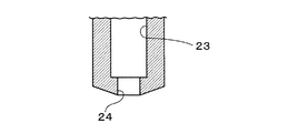
基板洗浄用2流体ノズル5において,ガスを供給するガス供給路21と,液体を供給する液体供給路22と,内部で形成した液滴を導出する導出路23を備え,導出路23の先端に,液滴を外部に噴射するための噴射口24を形成し,噴射口24の断面積Sbを,導出路23の断面積Saより小さく形成し,かつ,ガス供給路21の出口の断面積Scを,導出路23の断面積Saより小さく形成した。
【選択図】 図3
【Task】
An object of the present invention is to make the particle size and velocity of droplets uniform in a two-fluid nozzle for substrate cleaning in which a gas and a liquid are mixed inside and droplets are jetted together with the gas to clean the substrate. .
[Solution]
The substrate cleaning two-fluid nozzle 5 includes a gas supply path 21 for supplying a gas, a liquid supply path 22 for supplying a liquid, and a lead-out path 23 for leading out droplets formed therein. , An ejection port 24 for ejecting droplets to the outside is formed, a cross-sectional area Sb of the ejection port 24 is formed smaller than a cross-sectional area Sa of the outlet path 23, and a cross-sectional area Sc of the outlet of the gas supply path 21 Is formed smaller than the cross-sectional area Sa of the lead-out path 23.
[Selection] Figure 3
Description
本発明は,例えば半導体基板等の表面に付着している汚染物を除去する洗浄処理に使用する基板洗浄用2流体ノズル,及び,この基板洗浄用2流体ノズルを備えた基板洗浄装置に関するものである。 The present invention relates to a substrate cleaning two-fluid nozzle used in a cleaning process for removing contaminants adhering to the surface of, for example, a semiconductor substrate, and a substrate cleaning apparatus including the substrate cleaning two-fluid nozzle. is there.
例えば半導体デバイスの製造プロセスにおいては,半導体ウェハ(以下,「ウェハ」という。)を薬液や純水等の洗浄液によって洗浄し,ウェハに付着したパーティクル,有機汚染物,金属不純物のコンタミネーションを除去する基板洗浄装置が使用されている。かような基板洗浄装置の一例として,2流体ノズルを用いて洗浄液を液滴状にしてウェハの表面に噴射するものが知られている。 For example, in a semiconductor device manufacturing process, a semiconductor wafer (hereinafter referred to as “wafer”) is cleaned with a cleaning solution such as a chemical solution or pure water to remove contamination of particles, organic contaminants, and metal impurities adhering to the wafer. A substrate cleaning apparatus is used. As an example of such a substrate cleaning apparatus, there is known an apparatus that uses a two-fluid nozzle to form a cleaning liquid in droplets and spray it onto the surface of a wafer.
従来,基板洗浄用2流体ノズルとして,ノズルの内部においてガスと液体を混合して液滴を形成する内部混合型のものと,ノズルの外部においてガスと液体を混合して液滴を形成する外部混合型のものが知られている(例えば,特許文献1参照)。また,内部混合型の一例として,内部で形成した液滴とガスを直管内に通過させて液滴を加速させ,十分な速度にして気中に噴射するようにしたものが提案されている(例えば,特許文献2参照)。 Conventionally, as a two-fluid nozzle for cleaning a substrate, an internal mixing type in which gas and liquid are mixed inside the nozzle to form droplets, and an outside in which gas and liquid are mixed outside the nozzle to form droplets A mixed type is known (for example, see Patent Document 1). In addition, as an example of the internal mixing type, there has been proposed a method in which droplets and gas formed inside are passed through a straight pipe to accelerate the droplets and jet them into the air at a sufficient speed ( For example, see Patent Document 2).
しかしながら,従来の基板洗浄用2流体ノズルにあっては,液滴の粒径のばらつきが大きく,大粒の液滴がウェハの表面に噴射され,ウェハの表面に形成された微細なパターンに損傷を与える危険があった。特に,液滴を加速させるための直管を備えた内部混合型ノズルの場合,液滴が直管内を通過する間に,小さな液滴が集まって大粒の液滴になってしまう問題がある。また,噴射される液滴の数が多いほど汚染物除去性能が高いことが知られているが,液滴が十分に微粒化されなかったり,液滴が集まって大粒の液滴になったりすると,液滴の数が少なく,汚染物の除去性能が低くなる問題がある。また,汚染物除去性能を高めるため,ガスの流量を増加させて液滴を高速に加速させようとすると,大粒の液滴も高速で噴射されるので,ウェハの表面が損傷される。そのため,汚染物除去性能の向上に限界があった。 However, in the conventional two-fluid nozzle for substrate cleaning, the variation in droplet size is large, and large droplets are ejected onto the surface of the wafer, damaging the fine pattern formed on the surface of the wafer. There was a danger of giving. In particular, in the case of an internal mixing type nozzle provided with a straight pipe for accelerating liquid droplets, there is a problem that small liquid droplets gather and become large liquid droplets while the liquid droplets pass through the straight pipe. Also, it is known that the greater the number of ejected droplets, the higher the contaminant removal performance. However, if the droplets are not sufficiently atomized, or if the droplets collect and become large droplets. , There are problems that the number of droplets is small and the contaminant removal performance is low. In addition, if the gas flow rate is increased to increase the contaminant removal performance and the droplets are accelerated at a high speed, large droplets are also ejected at a high speed, which damages the wafer surface. For this reason, there was a limit to improving the contaminant removal performance.
さらに,内部混合型ノズルにあっては,液滴の噴射速度のばらつきが大きい問題があった。高速の液滴はウェハの表面に損傷を与える危険がある。また,低速の液滴は汚染物の除去性能が低い問題がある。 Furthermore, the internal mixing type nozzle has a problem that the dispersion speed of droplets is large. High speed droplets can damage the wafer surface. In addition, low-speed droplets have a problem of poor contaminant removal performance.
本発明の目的は,液滴の粒径と速度を均一化させることができる基板洗浄用2流体ノズル,及び,かかる基板洗浄用2流体ノズルを用いて基板を好適に洗浄することができる基板洗浄装置を提供することにある。 An object of the present invention is to provide a substrate cleaning two-fluid nozzle capable of uniformizing the particle size and velocity of the droplets, and a substrate cleaning capable of suitably cleaning a substrate using the substrate cleaning two-fluid nozzle. To provide an apparatus.
上記目的を達成するために,本発明によれば,ガスと液体とを内部で混合し,液滴をガスと共に噴射して基板を洗浄する基板洗浄用2流体ノズルであって,ガスを供給するガス供給路と,液体を供給する液体供給路と,内部で形成した液滴を導出する導出路を備え,前記導出路の先端に,液滴を外部に噴射するための噴射口を形成し,前記噴射口の断面積Sbを,前記導出路の断面積Saより小さく形成し,かつ,前記ガス供給路の出口の断面積Scを,前記導出路の断面積Saより小さく形成したことを特徴とする,基板洗浄用2流体ノズルが提供される。 In order to achieve the above object, according to the present invention, there is provided a two-fluid nozzle for cleaning a substrate which mixes a gas and a liquid inside and jets droplets together with the gas to clean the substrate, and supplies the gas. A gas supply path, a liquid supply path for supplying a liquid, and a lead-out path for deriving a droplet formed therein, and an ejection port for ejecting the droplet to the outside is formed at the tip of the lead-out path; The cross-sectional area Sb of the injection port is formed smaller than the cross-sectional area Sa of the lead-out path, and the cross-sectional area Sc of the outlet of the gas supply path is formed smaller than the cross-sectional area Sa of the lead-out path. A two-fluid nozzle for cleaning a substrate is provided.
前記導出路の断面積Saと前記噴射口の断面積Sbとの比Sa:Sbは,1:0.25〜0.81であっても良い。前記ガス供給路の出口の断面積Scを,前記噴射口の断面積Sbと同じか,もしくは,前記噴射口の断面積Sbより小さく形成しても良い。前記噴射口の断面積Sbと前記ガス供給路の出口の断面積Scとの比Sb:Scを,1:0.16〜0.87としても良い。前記ガス供給路の出口の断面積Scを,1.13〜6.16mm2としても良い。前記ガス供給路の出口の断面積Scを,1.77〜4.91mm2としても良い。前記導出路を直線状に形成し,かつ,前記導出路の断面積Saを一定としても良い。前記導出路の長さL1を,10〜90mmとしても良い。前記噴射口の長さL2を,30mm以下としても良い。 The ratio Sa: Sb between the cross-sectional area Sa of the outlet path and the cross-sectional area Sb of the injection port may be 1: 0.25 to 0.81. The cross-sectional area Sc at the outlet of the gas supply path may be the same as the cross-sectional area Sb of the injection port or smaller than the cross-sectional area Sb of the injection port. The ratio Sb: Sc between the cross-sectional area Sb of the injection port and the cross-sectional area Sc of the outlet of the gas supply path may be set to 1: 0.16 to 0.87. The cross-sectional area Sc at the outlet of the gas supply path may be 1.13 to 6.16 mm 2 . The cross-sectional area Sc at the outlet of the gas supply path may be 1.77 to 4.91 mm 2 . The lead-out path may be formed in a straight line, and the cross-sectional area Sa of the lead-out path may be constant. The length L1 of the lead-out path may be 10 to 90 mm. The length L2 of the injection port may be 30 mm or less.
本発明の基板洗浄用2流体ノズルは,例えば,前記ガス供給路を囲む環状の液体導入路を備え,前記ガス供給路を前記導出路と同軸上に配置し,前記液体供給路を前記液体導入路の外周面に開口させ,前記液体導入路に,先端側に向かうに従い径が小さくなるテーパ部を形成し,前記テーパ部を前記ガス供給路と前記導出路の間に開口させ,前記ガス供給路から供給されたガスと前記液体導入路から導入された液体を混合させて液滴を形成し,前記液滴を前記導出路を経て導出する構成としても良い。前記噴射口を,出口側周縁の縦断面形状が直角又は鋭角になるように形成しても良い。 The substrate cleaning two-fluid nozzle of the present invention includes, for example, an annular liquid introduction path surrounding the gas supply path, the gas supply path is arranged coaxially with the outlet path, and the liquid supply path is arranged as the liquid introduction path. An opening is formed on the outer peripheral surface of the passage, a tapered portion having a diameter that decreases toward the tip side is formed in the liquid introduction passage, the tapered portion is opened between the gas supply passage and the outlet passage, and the gas supply The gas supplied from the channel and the liquid introduced from the liquid introduction channel may be mixed to form droplets, and the droplets may be derived via the extraction channel. You may form the said injection port so that the longitudinal cross-sectional shape of an outlet side periphery may become a right angle or an acute angle.
また本発明によれば,上記基板洗浄用2流体ノズルと,基板を略水平に保持するスピンチャックと,前記基板の上方において前記洗浄用2流体ノズルを移動させる駆動機構を備えたことを特徴とする,基板洗浄装置が提供される。 Further, according to the present invention, the substrate cleaning two-fluid nozzle, a spin chuck that holds the substrate substantially horizontally, and a drive mechanism that moves the cleaning two-fluid nozzle above the substrate are provided. A substrate cleaning apparatus is provided.
本発明によれば,導出路の先端に噴射口を設け,液滴を噴射口に通過させることで,液滴を十分に微粒化することができる。導出路の途中,導出路内壁で大粒の液滴が形成されても,噴射口において再微粒化され,液滴の粒径が均一化する。また,導出路,噴射口,液体供給路,ガス供給路の各直径を適切な大きさとすることで,液体とガスを適当な流量で混合し,液滴を十分に微粒化して噴射することができる。導出路,噴射口を適切な長さとすることで,十分に微粒化した液滴を,適切な速度で噴射することができる。従って,基板洗浄用2流体ノズルの汚染物除去性能を向上させることができる。さらに,液滴の速度を均一化させることができる。また,本発明の基板洗浄装置によれば,基板表面を損傷することなく汚染物除去性能を向上させることができる。 According to the present invention, the droplet can be sufficiently atomized by providing the ejection port at the leading end of the outlet path and allowing the droplet to pass through the ejection port. Even if a large droplet is formed on the inner wall of the outlet channel in the middle of the outlet channel, it is re-atomized at the injection port and the particle size of the droplet becomes uniform. In addition, by setting the diameters of the outlet, injection port, liquid supply path, and gas supply path to appropriate sizes, the liquid and gas can be mixed at an appropriate flow rate, and droplets can be sufficiently atomized and ejected. it can. By setting the lead-out path and the ejection port to an appropriate length, it is possible to eject sufficiently atomized droplets at an appropriate speed. Therefore, the contaminant removal performance of the two-fluid nozzle for substrate cleaning can be improved. Furthermore, the speed of the droplets can be made uniform. Moreover, according to the substrate cleaning apparatus of the present invention, the contaminant removal performance can be improved without damaging the substrate surface.
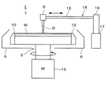
以下,本発明の好ましい実施の形態を,基板の一例としてウェハWの表面を洗浄するように構成された基板洗浄装置1に基づいて説明する。図1に示すように,本発明の実施の形態にかかる基板洗浄装置1は,略円板形状のウェハWを略水平に保持するスピンチャック2と,ガスと液体とを内部で混合し,液滴をガスと共に噴射する本発明の実施の形態にかかる2流体ノズル5と,スピンチャック2に保持されたウェハWの周囲を包囲するカップ6を備えている。
Hereinafter, a preferred embodiment of the present invention will be described based on a
図2に示すように,スピンチャック2は,上部に3個の保持部材10を備えており,これら3個の保持部材10をウェハWの周縁3箇所にそれぞれ当接させることによりウェハWを保持するようになっている。図1に示すように,スピンチャック2は,モータ12に接続されている。このモータ12の駆動により,スピンチャック2を回転させ,ウェハWをスピンチャック2と一体的に略水平面内で回転させるようになっている。
As shown in FIG. 2, the
2流体ノズル5は,スピンチャック2に保持されたウェハWの上方に略水平に配置されたノズルアーム15の先端に取り付けられている。ノズルアーム15の基端は,カップ6の外側において略鉛直方向に向けて配置された回転軸16に固定されており,回転軸16には駆動部17が接続されている。本実施の形態において,2流体ノズル5を移動させる駆動機構18は,ノズルアーム15,回転軸16,駆動部17によって構成されている。この駆動部17の駆動により,ノズルアーム15を回転軸16を中心として略水平面内で回転させ,2流体ノズル5をノズルアーム15と一体的に,少なくともウェハWの中央部上方からウェハWの周縁上方まで移動させることができる。また,駆動部17の駆動により回転軸16を昇降させ,2流体ノズル5をノズルアーム15,回転軸16と一体的に昇降させることができる。
The two-
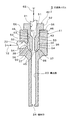
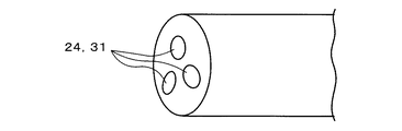
図3に示すように,2流体ノズル5は,2流体ノズル5の内部に例えば窒素(N2)等のガスを供給するガス供給路21と,2流体ノズル5の内部に例えば純水(DIW)等の液体を供給する液体供給路22と,2流体ノズル5の内部で形成した液滴Dと窒素ガスの噴流を導出する導出路23とを備えた,内部混合型の基板洗浄用2流体ノズルである。導出路23の先端には,液滴Dを外部に噴射させるための噴射口24が形成されている。
As shown in FIG. 3, the two-
ガス供給路21は導出路23と同軸上に配置されている。ガス供給路21の出口部分には,絞り部31が形成されている。絞り部31は,上流側の部分よりも断面積が小さくなるように形成されている。絞り部31の出口は,導出路23の入口に近接させて配置されている。なお,絞り部31の断面積は入口から出口まで一定であることが好ましく,絞り部31の断面形状は例えば円形又は楕円形等であることが好ましい。図示のように,絞り部31の断面積が入口から出口まで一定である場合は,ガス供給路23の出口の断面積Scは,絞り部31の断面積に等しい。
The
ガス供給路21の周囲には,ガス供給路21の絞り部31を囲むように環状に形成された液体導入路32が形成されている。液体供給路22は液体導入路32に接続されており,液体導入路32に純水を供給するようになっている。ガス供給路21は,液体導入路32の内側を通過するように配置されている。この液体導入路32は,環状の断面形状を有する筒状に形成されている。液体導入路32には,環状溝36と,先端側(図3において下側)に向かうに従い内径及び外径が小さくなるように形成されたテーパ部37が形成されている。テーパ部37は環状溝36より先端側に形成されており,テーパ部37の出口は,ガス供給路21の絞り部31の出口と導出路23の入口の間に,環状に開口している。従って,液体導入路32に導入された純水は,導出路23の入口付近において,ガス供給路21の絞り部31から供給された窒素ガスと混合し,液滴Dを形成するようになっている。液体導入路32の基端側(図3において上側)は閉口になっている。なお,テーパ部37の傾斜は,例えばガス供給路21及び導出路23に対して約45゜程度の角度をなすようにすると良い。
Around the
液体供給路22は,液体導入路32の環状溝36に対して適宜の角度をなすように設けられており,環状溝36の外周面に開口している。図示の例では,液体供給路22は,ガス供給路21と略平行な環状溝36の外周面に対して,略垂直な角度で設けられている。液体供給路22の出口部分には,絞り部38が形成されている。絞り部38は,上流側の部分よりも断面積が小さいオリフィス状に形成されている。そして,絞り部38の出口が環状溝36の内面に開口するように設けられている。絞り部38の断面積は入口から出口まで一定であることが好ましく,絞り部38の断面形状は例えば円形又は楕円形等であることが好ましい。図示のように,絞り部38の断面積が入口から出口まで一定である場合は,液体供給路22の出口の断面積Sdは,絞り部38の断面積に等しい。
The
導出路23は,前述のようにガス供給路21の絞り部31と同軸上に配置され,ガス供給路21と液体導入路32に連通している。導出路23は直線状に形成され,かつ,導出路23の断面積Saは入口から出口まで一定であることが好ましく,導出路23の断面形状は例えば円形又は楕円形等であることが好ましい。図4に示すように,ガス供給路21から供給された窒素ガスN2と液体導入路32から導入された純水DIWは,導出路23の入口付近において混合し,これにより,純水の液滴Dが無数に形成され,形成された液滴Dが窒素ガスN2と共に導出路23を経て導出されるようになっている。
As described above, the
噴射口24は,導出路23よりも断面積が小さいオリフィス状に形成されている。このように導出路23よりも断面積が小さいオリフィス状の噴射口24がない場合は,導出路23内壁に沿って成長したミスト状の液滴Dがそのまま吐出されてしまう。噴射口24の断面積Sbは入口から出口まで一定であることが好ましく,噴射口24の断面形状は例えば円形又は楕円形等であることが好ましい。導出路23内を通過した液滴Dは,噴射口24内を通過する間に再び微粒化されて噴射される。従って,液滴Dが導出路23の内壁に沿って移動する間に大きく成長してしまった場合でも,噴射口24を通過させることで液滴Dを十分に小さな粒径に微粒化して噴射することができるようになっている。
The
図4に示すように,2流体ノズル5は,噴射口24の出口側周縁に沿った部分の縦断面形状が直角になるように形成されていることが好ましい。即ち,噴射口24の内面と2流体ノズル5の先端部外側の平面が垂直になるように形成されていることが好ましい。このようにすると,噴射口24から噴射される液滴Dが,導出路23及び噴射口24が向かう方向に向かって直進しやすい。これに対し,噴射口24の出口側周縁に沿った部分の縦断面形状が直角に形成されておらず,丸みやテーパ面が形成されていると,液滴Dが丸みやテーパ面に沿って進み,噴射口24に対して斜めに飛び出し,噴射口24の外方に向かう液滴Dが多くなる。噴射口24の出口周縁を直角に形成することで,液滴Dの直進性が良好になり,ウェハWに対して液滴Dを勢い良く集中的に噴射することができ,汚染物除去性能を向上させることができる。なお,噴射口24の出口周縁を鋭角に形成しても,同様に,液滴Dの直進性が良好となる。
As shown in FIG. 4, the two-
また,図4に示すように,2流体ノズル5は,ガス供給路21,導出路23,噴射口24が,スピンチャック2に保持されたウェハWの上面に対して垂直方向に向かうようにしてノズルアーム15の先端に支持されている。即ち,ウェハWの上面に対して,液滴Dの噴流を略垂直に噴射するようになっている。
As shown in FIG. 4, the two-
なお,液滴Dの流れ方向における導出路23の長さL1が長すぎると,導出路23の内壁に沿って移動する液滴D同士が集まって大粒になりやすい。逆に導出路23の長さL1が短すぎると,導出路23内で液滴Dを十分に加速させることができず,噴射口24からの液滴Dの噴射速度が遅くなり,また,噴射口24において液滴Dの再微粒化が十分に行われないおそれがある。従って,導出路23の長さL1を適切な長さに形成することで,液滴Dを十分に微粒化された状態で十分に加速できるようにする必要がある。例えば,導出路23の長さL1は,約10〜90mm程度が良い。
If the length L1 of the
また,導出路23の断面積Saが大きすぎると,導出路23を通過する液滴Dの速度が遅くなるため,導出路23の内壁に沿って移動する液滴D同士が集まって大粒になりやすい。逆に導出路23の断面積Saが小さすぎると,導出路23内の窒素ガスN2の流量が少なく制限されるため,導出路23の入口付近における液滴Dの形成が好適に行われず,形成される液滴Dが望ましい粒径よりも大粒になるおそれがある。従って,導出路23の断面積Saを適切な大きさに形成し,液滴Dを十分に微粒化された状態で噴射口24に供給できるようにする必要がある。例えば,導出路23の断面形状が円形である場合,導出路23の直径aは,約1〜7mm程度が良く,さらに好ましくは,約3〜5mm程度が良い。導出路23の断面形状が楕円等,円形以外の形状である場合,導出路23の断面積は,約0.785〜38.5mm2程度が良く,さらに好ましくは,約7.07〜19.6mm2程度が良い。
Further, if the cross-sectional area Sa of the
さらに,噴射口24の断面積Sbが小さすぎると,噴射口24内の窒素ガスN2の流量が少なく制限され,ガス供給路21,導出路23内の窒素ガスN2の流量も少なく制限されるため,導出路23の入口付近における液滴Dの形成が好適に行われず,形成される液滴Dが望ましい粒径よりも大粒になるおそれがある。逆に噴射口24の断面積Sbが大きすぎると,噴射口24からの液滴Dの噴射速度が遅くなり,また,噴射口24において液滴Dが十分に再微粒化されないおそれがある。従って,噴射口24の断面積Sbを適切な大きさに形成することで,液滴Dを十分に小さく微粒化された状態で十分な速度で噴射できるようにする必要がある。例えば,噴射口24の断面形状が円形である場合,噴射口24の直径bは,約0.5〜6mm程度が良く,さらに好ましくは,約2〜4mm程度が良い。噴射口24の断面形状が楕円等,円形以外の形状である場合,噴射口24の断面積Sbは,約0.996〜28.3mm2程度が良く,さらに好ましくは,約3.14〜12.6mm2程度が良い。また,導出路23の断面形状,及び,噴射口24の断面形状がそれぞれ円形である場合,導出路23の直径aと噴射口24の直径bとの比率は,a:b=1:0.5〜0.9程度であることが好ましい。b<0.5aであると,導出路23内壁の大径ミストは微細化されるが,絞りがきつすぎることにより導出路23での速度と噴射口24を通過する際の速度差が大きすぎる。この速度差にミスト速度が追いつかず(加速できない),結果的にミスト速度がばらついてしまい,好ましくない。また使用上,N2流量の制御がよりシビアとなる為好ましくない。一方,b>0.9aのときは,ミスト速度の均一性は高いが,絞りが緩い為ミストの再微粒化が困難となる。これにより大径ミストが多く吐出される。このためミスト数が減ることとなり,結果的に洗浄性能が低下し,好ましくない。これに対して,b=0.5a〜0.9aのときは,適度な絞りの為,ミストの再微粒化,ミスト速度の均一性のバランスが良い。導出路23の断面形状,噴射口24の断面形状のいずれかが楕円等,円形以外の形状である場合は,導出路23の断面積と噴射口24の断面積との比率は,1:0.25〜0.81程度であることが好ましい。
Furthermore, the cross-sectional area Sb of the
液滴Dの流れ方向における噴射口24の長さL2は,導出路23の長さL1と比較して短く形成されている。この噴射口24の長さL2が長すぎると,噴射口24の内壁に沿って移動する液滴D同士が集まって大粒になってしまうおそれがある。そのため,噴射口24の長さL2は適切な長さにする必要がある。噴射口24の長さL2は,約30mm以下であることが好ましい。
The length L2 of the
一方,ガス供給路21においては,ガス供給路21の出口の断面積Sc,即ち絞り部31の断面積が小さすぎると,絞り部31から流出する窒素ガスN2の流量が少なく制限されるため,導出路23内で液滴Dを十分に加速させることができず,噴射口24からの液滴Dの噴射速度が遅くなってしまう。逆に,ガス供給路21の出口の断面積Scが大きすぎると,導出路23の入口付近における液滴Dの形成が好適に行われず,形成される液滴Dが望ましい粒径よりも大粒になるおそれがある。従って,ガス供給路21の出口の断面積Scを適切な大きさに形成することで,液滴Dを十分に小さく微粒化された状態で十分に加速できるようにする必要がある。さらに,ガス供給路21の出口の断面積Scは,導出路23の断面積Saよりも小さく形成することが好ましい。ガス供給路21の出口の断面積Scを,導出路23の断面積Saよりも小さく形成すれば,ガス供給路21の出口(絞り部31)を通過する際に,窒素ガスN2の流速が早くなり,液体導入路32から導入された純水DIWをミスト化する効果が高くなる。また,ミスト速度を均一化する効果もある。例えば,ガス供給路21の出口の断面形状が円形である場合,ガス供給路21の出口(絞り部31)の直径cは,約1.2〜2.8mm程度が良く,さらに好ましくは,約1.5〜2.5mm程度が良い。図5は,後述する実施例において調べた,ガス供給路21の出口の断面形状が円形である場合の直径cと洗浄性能(パーティクル除去性能)の関係を示すグラフである。直径cが約1.2〜2.8mm程度,好ましくは,約1.5〜2.5mm程度の範囲において,洗浄性能が高いことが分る。ガス供給路21の出口の断面形状が楕円等,円形以外の形状である場合,ガス供給路21の出口(絞り部31)の断面積Scは,約1.13〜6.16mm2程度が良く,さらに好ましくは,約1.77〜4.19mm2程度が良い。また,ガス供給路21の出口(絞り部31)の断面積Scは,噴射口24の断面積Sbと同じか,もしくは,噴射口24の断面積Sbより小さく形成することが好ましい。液滴Dを微粒化し,ミスト速度を均一化させるためには,ガス供給路21の出口(絞り部31)の断面積Scを,噴射口24の断面積Sb以下として,窒素ガスN2と純水DIWとの混合部でN2流速を上げることが効果的である。特に微細化されたパターンの洗浄などに対してはミスト速度を落とす必要があるが,そのような場合により効果的である。ガス供給路21の出口の断面形状,及び,噴射口24の断面形状がそれぞれ円形である場合,ガス供給路21の出口(絞り部31)の直径cと噴射口24の直径bとの比率は,b:c=1:0.4〜0.93程度であることが好ましい。例えば,噴射口24の直径bを3mmとした場合,c<0.4bのときは,N2供給圧力が通常使用範囲では,絞り部31での圧力損失が増大するため,N2流量を多くできずに吐出部のミスト流速が遅くなり,充分な洗浄力が得られず好ましくない。一方,ガス供給路21の出口(絞り部31)の直径c>0.93bのときは,混合部でのN2流速が遅いため,水滴の微細化が不十分であり,好ましくない。これに対して,c=0.4b〜0.93bのときは,適度なN2の流速となり,微細ミスト生成およびミスト速度の均一に好ましい。ガス供給路21の出口の断面形状,噴射口24の断面形状のいずれかが楕円等,円形以外の形状である場合は,噴射口24の断面積Sbとガス供給路21の出口(絞り部31)の断面積Scとの比率は,Sb:Sc=1:0.16〜0.87程度であることが好ましい。
On the other hand, in the
また,ガス供給路21の出口(絞り部31)から供給する窒素ガスN2の流量が少ないと,液滴Dを十分に微粒化させにくく,液滴Dの平均粒径が大きくなってしまう。ガス供給路21の出口(絞り部31)から供給する窒素ガスN2の流量が多いと,図1に示したカップ6内の排気が十分に行われず,パーティクルがウェハWに再付着する問題がある。ガス供給路21の出口(絞り部31)から流出させる窒素ガスN2の流量は,例えば約5〜200L/min.(normal)程度にすることが好ましく,さらに好ましくは,約10〜100L/min.(normal)程度が良い。さらに,ガス供給路21の出口(絞り部31)から供給する窒素ガスN2の流量が,液体供給路22の出口(絞り部38)から供給する純水DIWの流量に対して少ないと,液滴Dを十分に微粒化させにくく,液滴Dの平均粒径が大きくなってしまう。ガス供給路21の出口(絞り部31)から供給する窒素ガスN2の流量は,液体供給路22の出口(絞り部38)から供給する純水DIWの流量の約50倍以上であることが好ましく,さらに好ましくは,約100倍以上が良い。
Further, if the flow rate of the nitrogen gas N 2 supplied from the outlet (throttle portion 31) of the
液体供給路22においては,液体供給路22の出口の断面積Sd,即ち絞り部38の断面積が小さすぎると,絞り部38から流出する純水DIWの流量が少なく制限されるため,形成される液滴Dの個数が少なくなる。逆に,液体供給路22の出口の断面積Sdが大きすぎると,形成される液滴Dが望ましい粒径よりも大粒になるおそれがある。従って,液体供給路22の出口(絞り部38)の断面積Sdを適切な大きさに形成することで,液滴Dを望ましい個数と粒径で形成できるようにする必要がある。例えば,液体供給路22の出口(絞り部38)の断面形状が円形である場合,液体供給路22の出口(絞り部38)の直径dは,約0.5〜5mm程度が良く,さらに好ましくは,約1〜3mm程度が良い。液体供給路22の出口(絞り部38)の断面形状が楕円等,円形以外の形状である場合,液体供給路22の出口(絞り部38)の断面積Sdは,約0.196〜19.5mm2程度が良い。また,液体供給路22の出口(絞り部38)の断面形状,及び,噴射口24の断面形状がそれぞれ円形である場合,液体供給路22の出口(絞り部38)の直径dと噴射口24の直径bとの比率は,d:b=1:1〜3程度であることが好ましい。液体供給路22の出口(絞り部38)の断面形状,噴射口24の断面形状のいずれかが楕円等,円形以外の形状である場合は,液体供給路22の出口(絞り部38)の断面積Sdと噴射口24の断面積Sbとの比率は,Sd:Sb=1:1〜9程度であることが好ましい。
In the
また,絞り部38(液体供給路22)から供給する純水DIWの流量が少ないと,液滴Dの個数が少ないため洗浄効果が低くなる。絞り部38から供給する純水DIWの流量が多いと,液滴Dを十分に微粒化させにくく,液滴Dの平均粒径が大きくなってしまう。絞り部38から供給する純水DIWの流量は,例えば約20〜500mL/min.程度にすることが好ましく,さらに好ましくは,約100〜200mL/min.程度が良い。
Further, when the flow rate of the pure water DIW supplied from the throttle unit 38 (liquid supply path 22) is small, the cleaning effect is low because the number of droplets D is small. If the flow rate of pure water DIW supplied from the
図3に示すように,2流体ノズル5は,液体供給路22,液体導入路32,導出路23,噴射口24が形成されたノズル本体41と,ガス供給路21が形成されノズル本体41に係合される係合部材42によって構成されている。ノズル本体41の基端側には,断面円形状に形成されノズル本体41の基端側の外面に開口する空洞部43が形成されている。ノズル本体41の先端側には,導出路23が形成されている。空洞部43は,導出路23と同軸上に形成されている。空洞部43の先端と導出路23の入口の間は,空洞部43側から導出路23側に向かうに従い窄むように形成されたテーパ面45になっている。また,空洞部43の開口側には,ネジ溝46が形成されている。液体供給路22は,テーパ面45とネジ溝46の間において,空洞部43の内面に開口している。
As shown in FIG. 3, the two-
係合部材42は,空洞部43に挿入させる挿入体51と,ノズル本体41の基端側に配置する頭体52によって構成されている。挿入体51は,例えば,空洞部43の内径とほぼ同じ大きさの外径で形成された円柱状をなす大円柱部53と,大円柱部53の先端側に設けられ空洞部43の内径より小さな外径で形成された円柱状をなす小円柱部54と,小円柱部54より先端側に形成され先端側に向かうほど窄むように形成された円錐台状をなす円錐台部55を備えている。また,大円柱部53の外面には,空洞部43のネジ溝46と螺合するネジ溝56が設けられている。頭体52は,空洞部43の内径,大円柱部53の外径より大きな外径で形成されている。ガス供給路21は,頭体52の基端側の面から大円柱部53,小円柱部54,円錐台部55の各中央部を貫通するように設けられ,絞り部31の出口が円錐台部55の先端部の平面に開口するように形成されている。
The engaging
係合部材42の挿入体51を空洞部43に挿入して,ネジ溝46とネジ溝56を螺合させた状態では,小円柱部54の外面と空洞部43の内面との間に円環状の隙間,即ち液体導入路32が形成されるようになっている。また,円錐台部55の外面とテーパ面45の間に,環状の隙間,即ちテーパ部37が形成されるようになっている。頭体52は,空洞部43を塞ぎ,空洞部43の開口の周囲の面に密接するように備えられる。
In a state where the
なお,2流体ノズル5を構成するノズル本体41と係合部材42の材質としては,例えばPTFE(ポリテトラフルオロエチレン)等のフッ素系の樹脂等を使用することが好ましい。
In addition, as a material of the
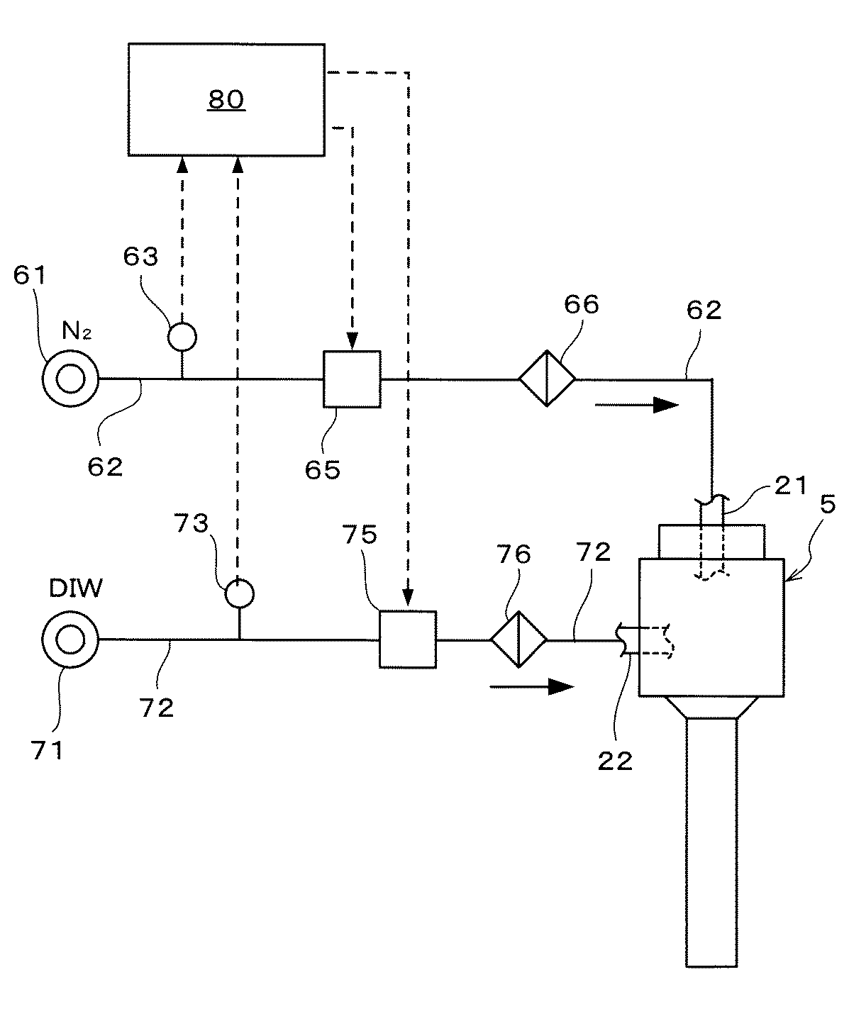
図6に示すように,ガス供給路21には,窒素ガス供給源61から窒素ガスを供給するガス供給配管62が接続されている。ガス供給配管62には,フローメーター63,流量調節弁65,及びフィルター66が,窒素ガス供給源61側からこの順に介設されている。また,液体供給路22には,純水供給源71から純水を供給する液体供給配管72が接続されている。液体供給配管72には,フローメーター73,流量調節弁75,及びフィルター76が,純水供給源71側からこの順に介設されている。
As shown in FIG. 6, a
また,流量調節弁65と流量調節弁75を操作する指令を出力する制御部80が設けられている。フローメーター63,73で検出される流量は,制御部80によって監視される。制御部80は,フローメーター63の流量検出値に基づいて,ガス供給配管62内に窒素ガスが所望の流量で流れるように,流量調節弁65の開度を調節する指令を出力する。また,制御部80は,フローメーター73の流量検出値に基づいて,液体供給配管72内に純水が所望の流量で流れるように,流量調節弁75の開度を調節する指令を出力するようになっている。
Further, a
さて,この洗浄装置1においては,先ず図示しない搬送アームにより未だ洗浄されていないウェハWを洗浄装置1内に搬入し,図1に示すようにウェハWをスピンチャック2に受け渡す。このときウェハWは表面(パターンが形成されている面)を上面として,スピンチャック2に保持される。ウェハWをスピンチャック2に受け渡すときは,図2において二点鎖線で示すように,2流体ノズル5及びノズルアーム15をカップ6の外側に退避させておく。ウェハWがスピンチャック2に受け渡されたら,駆動部17を駆動させてノズルアーム15を回転させ,図2において実線で示すように,2流体ノズル5をウェハWの上方に移動させ,液滴Dの噴射を開始する。一方,図1に示したモータ12の駆動によりスピンチャック2を回転させ,ウェハWの回転を開始させる。そして,2流体ノズル5をウェハWの中央部上方からウェハWの周縁部上方に向かって移動させながら,回転しているウェハWの表面に向かって噴流を噴射する。これにより,ウェハWの表面全体に噴流が噴射され,ウェハWの表面に付着していた汚染物が除去される。
In this
噴流は,以下に説明するようにして形成される。先ず,流量調節弁65を開いてガス供給配管62,ガス供給路21に窒素ガス供給源61から供給される窒素ガスN2を通流させる。ガス供給配管62内の窒素ガスN2の流量は,制御部80の指令によりフローメーター63の検出値に基づいて流量調節弁65が調節されることで,所望の値に制御される。従って,ガス供給路21に適切な流量で窒素ガスN2を供給することができる。ガス供給路21を通過した窒素ガスN2は,図4に示すように絞り部31から放出されて導出路23の入口に流入する。
The jet is formed as described below. First, the flow
このように窒素ガスN2を供給する一方で,流量調節弁75を開いて液体供給配管72,液体供給路22に純水供給源71から供給される純水DIWを通流させる。液体供給配管72内の純水DIWの流量は,制御部80の指令によりフローメーター73の検出値に基づいて流量調節弁75が調節されることで,所望の値に制御される。従って,液体供給路22に適切な流量で純水DIWを供給することができる。液体供給路22を通過した純水DIWは,図4に示すように絞り部38から液体導入路32の環状溝36に向かって略垂直方向に放出されて環状溝36に流入し,絞り部38の出口から環状溝36の内面に沿って環状に広がり,さらにテーパ部37全体に純水DIWが環状に流入する。そして,テーパ部37から導出路23の入口に向かって,純水DIWが斜めに放出される。
Thus, while supplying the nitrogen gas N 2 , the flow
ガス供給路21を通過した窒素ガスN2と,テーパ部37を通過した純水DIWは,導出路23の入口にそれぞれ放出され混合する。窒素ガスN2は,ガス供給路21の絞り部31から導出路23に向かって直線的に放出され,純水は,導出路23の入口に向かって,導出路23の入口の周囲全体から斜めに放出される。窒素ガスN2と純水DIWが混合した結果,窒素ガスN2に衝突した純水DIWが微粒子状になり,純水DIWの液滴Dが形成される。窒素ガスN2と純水DIWは,液滴Dが十分に小さい粒径で十分な個数で形成されるように,絞り部31とテーパ部37からそれぞれ適切な流量で供給される。
The nitrogen gas N 2 that has passed through the
液滴Dと窒素ガスN2の噴流は,導出路23内を経て導出され,噴射口24に向かう。液滴Dは,導出路23内を通過する間に窒素ガスN2の流れによって加速される。導出路23の長さL1は,液滴Dを十分に加速できる長さになっており,また,窒素ガスN2は,液滴Dを十分に加速できる適切な流量で導出路23に供給されるので,液滴Dを十分な速度に加速して噴射口24から噴射させ,ウェハWの表面に衝突させることができる。従って,ウェハWの表面から汚染物を好適に除去することができる。また,導出路23の長さL1は,導出路23内を通過する間に液滴D同士が集まって大粒になることを抑制するように適当な長さになっており,液滴Dが微粒子状のまま噴射口24に導出されるようになっている。
The jet of the droplet D and the nitrogen gas N 2 is led out through the lead-
導出路23内を通過する噴流中には,純水DIWと窒素ガスN2を混合させた際に十分に小さな粒径で形成されなかった液滴Dや,導出路23内を通過する間に導出路23の内壁に沿って大粒に成長した液滴Dが含まれているおそれがある。これらの大粒の液滴Dが混在していても,噴射口24を通過する間に再び微粒子化され,十分に小さい液滴Dに分裂するようになっているので,ウェハWの表面に大粒の液滴Dが衝突することを防止できる。従って,ウェハWの表面が損傷することを防止できる。また,大粒の液滴Dが噴射口24において複数の液滴Dに分裂するので,液滴Dの数が増加する。従って,多数の微粒子状の液滴DをウェハWの表面に衝突させることができるので,ウェハWの表面から汚染物を好適に除去することができる。さらに,噴射口24を設けない場合と比較して,液滴Dの粒径と噴射速度が均一化する効果がある。即ち,噴射速度が遅く汚染物除去に関与しない液滴Dや,噴射速度が速すぎてウェハWの表面を損傷するおそれがある液滴Dや,大粒の液滴Dを減少させることができ,多数の液滴Dを汚染物除去に好適な噴射速度で噴射させることができる。従って,汚染物除去性能を向上させながらも,大粒の液滴Dや高速の液滴DによるウェハWの表面の損傷を防止することができる。なお,ウェハWの表面を損傷せずに汚染物を除去するためには,液滴Dの粒径が約100μm以下程度であることが好ましく,速度が約80m/sec以下程度であることが好ましい。さらに好ましくは,液滴Dの粒径の平均値が約50μm以下程度,かつ,最大粒径が約100μm以下程度であり,液滴Dの速度の平均値が約40m/sec以上,約80m/sec以下程度になるようにすることが好ましい。
The jet in passing through the
噴射口24の出口側周縁の縦断面形状は直角になっているので,液滴Dの直進性が良く,ウェハWの表面に対して液滴Dが勢い良く衝突するため,ウェハWの表面から汚染物を好適に除去することができる。
Since the vertical cross-sectional shape of the peripheral edge on the outlet side of the
以上のようにして2流体ノズル5において液滴Dの噴流を生成し,噴流によってウェハWの表面全体を洗浄したら,制御部80の指令により流量調節弁65と流量調節弁75を閉じ,2流体ノズル5からの噴流の噴射を停止させる。そして,図2において二点鎖線で示すように,2流体ノズル5及びノズルアーム15をカップ6の外側に退避させる。また,モータ12の駆動を停止させ,スピンチャック2とウェハWの回転を停止させる。そして,搬送アーム(図示せず)を洗浄装置1内に進入させ,搬送アーム(図示せず)によってウェハWをスピンチャック2から受け取り,洗浄装置1から搬出する。こうして,洗浄装置1における処理が終了する。
As described above, when the jet of the droplet D is generated in the two-
かかる2流体ノズル5によれば,導出路23の先端にオリフィス状の噴射口24を設け,液滴Dを噴射口24に通過させることで,液滴Dを十分に小さな粒径の粒子状に再微粒化して噴射させることができる。大粒の液滴Dが形成されても,噴射口24において再微粒化されるので,液滴Dの粒径を小さな粒径に均一化させて噴射させることができる。従って,ウェハWの表面に大粒の液滴Dが衝突することを防止でき,ウェハWの表面が損傷することを防止できる。さらに,再微粒化によって多数の微粒子状の液滴Dが形成され,多数の液滴DをウェハWの表面に衝突させることができるので,汚染物の除去性能が向上する。また,導出路23,噴射口24を適切な長さとすることで,十分に微粒化した液滴Dを,適切な速度で噴射させることができる。従って,良好な汚染物除去性能が得られる。さらに,液滴Dの速度を均一化させることができる。即ち,多数の液滴Dを適切な噴射速度で噴射させることができるので,汚染物除去性能を向上させながらもウェハWの表面の損傷を防止することができる。また,本発明の洗浄装置1によれば,ウェハWの表面を損傷することなく汚染物除去性能を向上させることができる。
According to such a two-
以上,本発明の好適な実施の形態の一例を示したが,本発明はここで説明した形態に限定されない。例えば,本実施の形態においては,液体は純水とし,ガスは窒素ガスとしたが,かかるものに限定されず,液体は洗浄用の薬液等であっても良く,ガスは空気等であっても良い。また,基板は半導体ウェハに限らず,その他のLCD基板用ガラスやCD基板,プリント基板,セラミック基板などであっても良い。 Although an example of a preferred embodiment of the present invention has been described above, the present invention is not limited to the embodiment described here. For example, in the present embodiment, the liquid is pure water and the gas is nitrogen gas. However, the present invention is not limited to this, and the liquid may be a cleaning chemical or the like, and the gas may be air or the like. Also good. The substrate is not limited to a semiconductor wafer, but may be other LCD substrate glass, a CD substrate, a printed substrate, a ceramic substrate, or the like.
ガス供給路21,液体供給路22,液体導入路32の配置や形状は,実施の形態に示したものに限定されない。また,本実施の形態では,2流体ノズル5の構造の一例として,ノズル本体41と係合部材42によって構成され,ノズル本体41の小円柱部54とノズル本体41の空洞部43との間に液体導入路32が形成されているものを説明したが,2流体ノズル5の構成はかかるものに限定されない。
The arrangement and shape of the
本実施の形態では,噴射口24の出口側周縁に沿った部分の縦断面形状が直角になるように形成されていることとしたが,噴射口24の出口側周縁に沿った部分の縦断面形状は,図7に示すように,鋭角であっても良い。例えば,断面略円形をなす噴射口24の周囲を,先端に向かうに従い外径が小さくなるように形成し,噴射口24の出口の周囲に沿って略円錐台面が形成されるようにする。この場合も,噴射口24から噴射される液滴Dが,導出路23及び噴射口24が向かう方向に向かって直進しやすく,ウェハWに対して液滴Dを勢い良く集中的に噴射することができ,汚染物除去性能を向上させることができる。
In the present embodiment, the vertical cross-sectional shape of the portion along the outlet side periphery of the
また,噴射口24の断面形状と絞り部31の断面形状は,いずれも円形のものについて説明したが,これらの形状は,円形に限らず,任意の形状を採りえる。例えば図8に示すように,噴射口24や絞り部31を複数の孔(多孔)に形成しても良い。
Moreover, although the cross-sectional shape of the
導出路23の直径a,噴射口24の直径b,絞り部31の直径c,絞り部38の直径dについて,表1に示すように,a:b=1:0.75,b:c=1:0.67,a:c=1:0.5,d:b=1:3とした。なお,導出路23の断面形状,噴射口24の断面形状,絞り部31の断面形状,絞り部38の断面形状は,いずれも円形である。この2流体ノズル5を用いてウェハWの洗浄実験を行い,2流体ノズル5の汚染物除去性能を確認した。その結果,ウェハWの表面を損傷することなく,良好な汚染物除去性能が得られた。
As shown in Table 1, the diameter a of the lead-
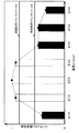
実施例1で用いた2流体ノズル5において,ガス供給路21の出口(絞り部31)の直径cを変化させ,直径cと洗浄性能(パーティクル除去率)の関係を調べた。その結果,図5,図9を得た。なお,図5では,最も洗浄性能が高かった直径c=2.0mmのときのパーティクル除去率を1として,各直径cのときのパーティクル除去率を,除去率1に対する比率で示した。図5に示されるように,ガス供給路21の出口(絞り部31)の直径cが1.2〜2.8mmの範囲では,有効なパーティクル除去率を確保できた。特に,直径cが1.5〜2.5mmの範囲では,最適と思われるパーティクル除去率を確保できた。また,ガス供給路21の出口(絞り部31)の直径cが小さいほど,ミスト径が小さくなり,速度分布も均一化することがわかった。特に低流量でミストを微細化するには,直径cが小さいほど有利であった。図9に示されるように,直径cが1.5mmと2.0mmのときに比べ,直径cが3.0mmのときは,微細ミスト生成が困難となった。
In the two-
本発明は,例えば半導体基板等の表面に付着している汚染物の除去などに好適に利用することができる。 The present invention can be suitably used for removing contaminants attached to the surface of a semiconductor substrate, for example.
D 液滴
W ウェハ
1 洗浄装置
2 スピンチャック
5 2流体ノズル
18 駆動機構
21 ガス供給路
22 液体供給路
23 導出路
24 噴射口
31 絞り部
32 液体導入路
37 テーパ部
38 絞り部
D
Claims (12)
ガスを供給するガス供給路と,液体を供給する液体供給路と,内部で形成した液滴を導出する導出路を備え,
前記導出路の先端に,液滴を外部に噴射するための噴射口を形成し,
前記噴射口の断面積Sbを,前記導出路の断面積Saより小さく形成し,かつ,前記ガス供給路の出口の断面積Scを,前記導出路の断面積Saより小さく形成したことを特徴とする,基板洗浄用2流体ノズル。 A two-fluid nozzle for substrate cleaning that mixes gas and liquid inside and jets droplets with gas to clean the substrate,
A gas supply path for supplying gas, a liquid supply path for supplying liquid, and a discharge path for deriving droplets formed inside are provided.
An ejection port for ejecting droplets to the outside is formed at the tip of the outlet path,
The cross-sectional area Sb of the injection port is formed smaller than the cross-sectional area Sa of the lead-out path, and the cross-sectional area Sc of the outlet of the gas supply path is formed smaller than the cross-sectional area Sa of the lead-out path. 2 fluid nozzle for substrate cleaning.
前記ガス供給路を前記導出路と同軸上に配置し,
前記液体供給路を前記液体導入路の外周面に開口させ,
前記液体導入路に,先端側に向かうに従い径が小さくなるテーパ部を形成し,
前記テーパ部を前記ガス供給路と前記導出路の間に開口させ,
前記ガス供給路から供給されたガスと前記液体導入路から導入された液体を混合させて液滴を形成し,前記液滴を前記導出路を経て導出する構成としたことを特徴とする,請求項1〜9のいずれかに記載の基板洗浄用2流体ノズル。 An annular liquid introduction path surrounding the gas supply path;
The gas supply path is arranged coaxially with the outlet path;
Opening the liquid supply path on the outer peripheral surface of the liquid introduction path;
In the liquid introduction path, a tapered portion having a diameter that decreases toward the tip side is formed,
Opening the tapered portion between the gas supply path and the outlet path;
The gas supplied from the gas supply path and the liquid introduced from the liquid introduction path are mixed to form droplets, and the droplets are led out through the lead-out path. Item 10. A two-fluid nozzle for cleaning a substrate according to any one of Items 1 to 9.
基板を略水平に保持するスピンチャックと,
前記基板の上方において前記洗浄用2流体ノズルを移動させる駆動機構を備えたことを特徴とする,基板洗浄装置。 A two-fluid nozzle for cleaning a substrate according to any one of claims 1 to 11,
A spin chuck that holds the substrate substantially horizontally;
A substrate cleaning apparatus, comprising a drive mechanism for moving the cleaning two-fluid nozzle above the substrate.
Priority Applications (1)
| Application Number | Priority Date | Filing Date | Title |
|---|---|---|---|
| JP2005064781A JP4464850B2 (en) | 2004-03-09 | 2005-03-09 | Substrate cleaning two-fluid nozzle and substrate cleaning device |
Applications Claiming Priority (2)
| Application Number | Priority Date | Filing Date | Title |
|---|---|---|---|
| JP2004066392 | 2004-03-09 | ||
| JP2005064781A JP4464850B2 (en) | 2004-03-09 | 2005-03-09 | Substrate cleaning two-fluid nozzle and substrate cleaning device |
Publications (2)
| Publication Number | Publication Date |
|---|---|
| JP2005294819A true JP2005294819A (en) | 2005-10-20 |
| JP4464850B2 JP4464850B2 (en) | 2010-05-19 |
Family
ID=35327355
Family Applications (1)
| Application Number | Title | Priority Date | Filing Date |
|---|---|---|---|
| JP2005064781A Expired - Lifetime JP4464850B2 (en) | 2004-03-09 | 2005-03-09 | Substrate cleaning two-fluid nozzle and substrate cleaning device |
Country Status (1)
| Country | Link |
|---|---|
| JP (1) | JP4464850B2 (en) |
Cited By (15)
| Publication number | Priority date | Publication date | Assignee | Title |
|---|---|---|---|---|
| KR100728882B1 (en) * | 2005-12-29 | 2007-06-15 | 주식회사 케이씨텍 | Airflow injection module for substrate cleaning and substrate cleaning device using the same |
| JP2007227878A (en) * | 2006-01-26 | 2007-09-06 | Dainippon Screen Mfg Co Ltd | Substrate processing apparatus and substrate processing method |
| JP2007242892A (en) * | 2006-03-08 | 2007-09-20 | Asahi Sunac Corp | Nozzle device and cleaning device provided with the nozzle device |
| KR100786332B1 (en) * | 2006-12-29 | 2007-12-14 | 세메스 주식회사 | Substrate Cleaning Device |
| JP2008041931A (en) * | 2006-08-07 | 2008-02-21 | Matsushita Electric Ind Co Ltd | Substrate processing method |
| KR100904350B1 (en) | 2006-12-15 | 2009-06-23 | 다이닛뽕스크린 세이조오 가부시키가이샤 | Two-fluid nozzle, substrate processing apparatus, and substrate processing method |
| JP2009158703A (en) * | 2007-12-26 | 2009-07-16 | Tokyo Electron Ltd | Two-fluid nozzle, substrate cleaning apparatus and substrate cleaning method |
| US8580039B2 (en) | 2009-08-31 | 2013-11-12 | Hitachi Cable, Ltd. | Surface treatment method of metal member and cleaning nozzle |
| KR20170084073A (en) | 2014-11-11 | 2017-07-19 | 가부시키가이샤 에바라 세이사꾸쇼 | Substrate washing device |
| JP2018101790A (en) * | 2013-11-22 | 2018-06-28 | 株式会社荏原製作所 | Substrate cleaning apparatus and substrate processing apparatus |
| KR20180111382A (en) * | 2017-03-31 | 2018-10-11 | (주) 엔피홀딩스 | Steam cleaning system and steam cleaning method using the same |
| KR20190019600A (en) * | 2017-08-18 | 2019-02-27 | 삼성전자주식회사 | Two-fluid nozzle and substrate processing apparatus having the same |
| US10991602B2 (en) | 2016-05-09 | 2021-04-27 | Ebara Corporation | Substrate washing device |
| CN114334713A (en) * | 2020-10-09 | 2022-04-12 | 东京毅力科创株式会社 | Substrate processing apparatus |
| KR20240061715A (en) * | 2022-11-01 | 2024-05-08 | 네이처이앤티 주식회사 | Waste drum cleaning system using steam and air |
Families Citing this family (1)
| Publication number | Priority date | Publication date | Assignee | Title |
|---|---|---|---|---|
| KR101825875B1 (en) * | 2017-03-22 | 2018-03-22 | 김용관 | Draft beer supply |
-
2005
- 2005-03-09 JP JP2005064781A patent/JP4464850B2/en not_active Expired - Lifetime
Cited By (19)
| Publication number | Priority date | Publication date | Assignee | Title |
|---|---|---|---|---|
| KR100728882B1 (en) * | 2005-12-29 | 2007-06-15 | 주식회사 케이씨텍 | Airflow injection module for substrate cleaning and substrate cleaning device using the same |
| JP2007227878A (en) * | 2006-01-26 | 2007-09-06 | Dainippon Screen Mfg Co Ltd | Substrate processing apparatus and substrate processing method |
| JP2007242892A (en) * | 2006-03-08 | 2007-09-20 | Asahi Sunac Corp | Nozzle device and cleaning device provided with the nozzle device |
| JP2008041931A (en) * | 2006-08-07 | 2008-02-21 | Matsushita Electric Ind Co Ltd | Substrate processing method |
| KR100904350B1 (en) | 2006-12-15 | 2009-06-23 | 다이닛뽕스크린 세이조오 가부시키가이샤 | Two-fluid nozzle, substrate processing apparatus, and substrate processing method |
| KR100786332B1 (en) * | 2006-12-29 | 2007-12-14 | 세메스 주식회사 | Substrate Cleaning Device |
| JP2009158703A (en) * | 2007-12-26 | 2009-07-16 | Tokyo Electron Ltd | Two-fluid nozzle, substrate cleaning apparatus and substrate cleaning method |
| US8580039B2 (en) | 2009-08-31 | 2013-11-12 | Hitachi Cable, Ltd. | Surface treatment method of metal member and cleaning nozzle |
| JP2018101790A (en) * | 2013-11-22 | 2018-06-28 | 株式会社荏原製作所 | Substrate cleaning apparatus and substrate processing apparatus |
| KR20170084073A (en) | 2014-11-11 | 2017-07-19 | 가부시키가이샤 에바라 세이사꾸쇼 | Substrate washing device |
| KR20210137232A (en) | 2014-11-11 | 2021-11-17 | 가부시키가이샤 에바라 세이사꾸쇼 | Substrate washing device |
| US10991602B2 (en) | 2016-05-09 | 2021-04-27 | Ebara Corporation | Substrate washing device |
| KR20180111382A (en) * | 2017-03-31 | 2018-10-11 | (주) 엔피홀딩스 | Steam cleaning system and steam cleaning method using the same |
| KR101976799B1 (en) * | 2017-03-31 | 2019-08-28 | (주) 엔피홀딩스 | Steam cleaning system and steam cleaning method using the same |
| KR20190019600A (en) * | 2017-08-18 | 2019-02-27 | 삼성전자주식회사 | Two-fluid nozzle and substrate processing apparatus having the same |
| KR101980618B1 (en) * | 2017-08-18 | 2019-08-28 | 삼성전자주식회사 | Two-fluid nozzle and substrate processing apparatus having the same |
| CN114334713A (en) * | 2020-10-09 | 2022-04-12 | 东京毅力科创株式会社 | Substrate processing apparatus |
| KR20240061715A (en) * | 2022-11-01 | 2024-05-08 | 네이처이앤티 주식회사 | Waste drum cleaning system using steam and air |
| KR102906576B1 (en) * | 2022-11-01 | 2025-12-31 | 네이처이앤티 주식회사 | Waste drum cleaning system using steam and air |
Also Published As
| Publication number | Publication date |
|---|---|
| JP4464850B2 (en) | 2010-05-19 |
Similar Documents
| Publication | Publication Date | Title |
|---|---|---|
| KR100760893B1 (en) | Two-fluid nozzle for cleaning substrate and substrate cleaning device | |
| JP4464850B2 (en) | Substrate cleaning two-fluid nozzle and substrate cleaning device | |
| TWI443722B (en) | Substrate processing apparatus and substrate processing method | |
| KR100276620B1 (en) | Secondary nozzle for cleaning and cleaning device and cleaning method using same | |
| US20070169793A1 (en) | Substrate treatment apparatus and substrate treatment method | |
| CN104841660B (en) | Gas-liquid two-phase atomization cleaner and cleaning method | |
| CN100541709C (en) | Substrate processing apparatus and substrate processing method | |
| US7600522B2 (en) | Substrate treatment method and substrate treatment apparatus | |
| TW201720538A (en) | Two-phase flow atomization jet cleaning device | |
| KR20170137928A (en) | Substrate treatment apparatus | |
| JP2004349501A (en) | Substrate processing method and substrate processing apparatus | |
| JP4222876B2 (en) | Substrate processing equipment | |
| JP2009054755A (en) | Substrate treating equipment | |
| JP2008130643A (en) | Nozzle, substrate treatment equipment and substrate treating method | |
| JP4707730B2 (en) | Semiconductor wafer cleaning apparatus and semiconductor wafer cleaning method | |
| JP2008159989A (en) | Nozzle, substrate treatment apparatus, and substrate treatment method | |
| JP2006128332A (en) | Equipment and method for treating substrate | |
| CN120618725B (en) | A dual-fluid nozzle and substrate processing equipment | |
| JPH05168982A (en) | Treating liquid feed nozzle | |
| JP2003188072A (en) | Spin processing apparatus and spin processing method |
Legal Events
| Date | Code | Title | Description |
|---|---|---|---|
| A621 | Written request for application examination |
Free format text: JAPANESE INTERMEDIATE CODE: A621 Effective date: 20070528 |
|
| A977 | Report on retrieval |
Free format text: JAPANESE INTERMEDIATE CODE: A971007 Effective date: 20090629 |
|
| A131 | Notification of reasons for refusal |
Free format text: JAPANESE INTERMEDIATE CODE: A131 Effective date: 20090707 |
|
| A521 | Request for written amendment filed |
Free format text: JAPANESE INTERMEDIATE CODE: A523 Effective date: 20090907 |
|
| TRDD | Decision of grant or rejection written | ||
| A01 | Written decision to grant a patent or to grant a registration (utility model) |
Free format text: JAPANESE INTERMEDIATE CODE: A01 Effective date: 20100209 |
|
| A01 | Written decision to grant a patent or to grant a registration (utility model) |
Free format text: JAPANESE INTERMEDIATE CODE: A01 |
|
| A61 | First payment of annual fees (during grant procedure) |
Free format text: JAPANESE INTERMEDIATE CODE: A61 Effective date: 20100219 |
|
| FPAY | Renewal fee payment (event date is renewal date of database) |
Free format text: PAYMENT UNTIL: 20130226 Year of fee payment: 3 |
|
| R150 | Certificate of patent or registration of utility model |
Free format text: JAPANESE INTERMEDIATE CODE: R150 Ref document number: 4464850 Country of ref document: JP Free format text: JAPANESE INTERMEDIATE CODE: R150 |
|
| S111 | Request for change of ownership or part of ownership |
Free format text: JAPANESE INTERMEDIATE CODE: R313115 |
|
| FPAY | Renewal fee payment (event date is renewal date of database) |
Free format text: PAYMENT UNTIL: 20130226 Year of fee payment: 3 |
|
| R350 | Written notification of registration of transfer |
Free format text: JAPANESE INTERMEDIATE CODE: R350 |
|
| FPAY | Renewal fee payment (event date is renewal date of database) |
Free format text: PAYMENT UNTIL: 20140226 Year of fee payment: 4 |
|
| R250 | Receipt of annual fees |
Free format text: JAPANESE INTERMEDIATE CODE: R250 |
|
| R250 | Receipt of annual fees |
Free format text: JAPANESE INTERMEDIATE CODE: R250 |
|
| R250 | Receipt of annual fees |
Free format text: JAPANESE INTERMEDIATE CODE: R250 |
|
| S531 | Written request for registration of change of domicile |
Free format text: JAPANESE INTERMEDIATE CODE: R313531 |
|
| R350 | Written notification of registration of transfer |
Free format text: JAPANESE INTERMEDIATE CODE: R350 |
|
| R250 | Receipt of annual fees |
Free format text: JAPANESE INTERMEDIATE CODE: R250 |
|
| R250 | Receipt of annual fees |
Free format text: JAPANESE INTERMEDIATE CODE: R250 |
|
| R250 | Receipt of annual fees |
Free format text: JAPANESE INTERMEDIATE CODE: R250 |
|
| R250 | Receipt of annual fees |
Free format text: JAPANESE INTERMEDIATE CODE: R250 |
|
| R250 | Receipt of annual fees |
Free format text: JAPANESE INTERMEDIATE CODE: R250 |
|
| R250 | Receipt of annual fees |
Free format text: JAPANESE INTERMEDIATE CODE: R250 |
|
| R250 | Receipt of annual fees |
Free format text: JAPANESE INTERMEDIATE CODE: R250 |
|
| R250 | Receipt of annual fees |
Free format text: JAPANESE INTERMEDIATE CODE: R250 |
|
| R250 | Receipt of annual fees |
Free format text: JAPANESE INTERMEDIATE CODE: R250 |
|
| R250 | Receipt of annual fees |
Free format text: JAPANESE INTERMEDIATE CODE: R250 |
|
| EXPY | Cancellation because of completion of term |