JP2005293581A - Multi-system game controller that operates in multiple usb modes - Google Patents
Multi-system game controller that operates in multiple usb modes Download PDFInfo
- Publication number
- JP2005293581A JP2005293581A JP2005094740A JP2005094740A JP2005293581A JP 2005293581 A JP2005293581 A JP 2005293581A JP 2005094740 A JP2005094740 A JP 2005094740A JP 2005094740 A JP2005094740 A JP 2005094740A JP 2005293581 A JP2005293581 A JP 2005293581A
- Authority
- JP
- Japan
- Prior art keywords
- usb
- host
- game controller
- video game
- controller
- Prior art date
- Legal status (The legal status is an assumption and is not a legal conclusion. Google has not performed a legal analysis and makes no representation as to the accuracy of the status listed.)
- Pending
Links
Images
Classifications
-
- A—HUMAN NECESSITIES
- A63—SPORTS; GAMES; AMUSEMENTS
- A63F—CARD, BOARD, OR ROULETTE GAMES; INDOOR GAMES USING SMALL MOVING PLAYING BODIES; VIDEO GAMES; GAMES NOT OTHERWISE PROVIDED FOR
- A63F13/00—Video games, i.e. games using an electronically generated display having two or more dimensions
- A63F13/20—Input arrangements for video game devices
- A63F13/23—Input arrangements for video game devices for interfacing with the game device, e.g. specific interfaces between game controller and console
- A63F13/235—Input arrangements for video game devices for interfacing with the game device, e.g. specific interfaces between game controller and console using a wireless connection, e.g. infrared or piconet
-
- B—PERFORMING OPERATIONS; TRANSPORTING
- B23—MACHINE TOOLS; METAL-WORKING NOT OTHERWISE PROVIDED FOR
- B23Q—DETAILS, COMPONENTS, OR ACCESSORIES FOR MACHINE TOOLS, e.g. ARRANGEMENTS FOR COPYING OR CONTROLLING; MACHINE TOOLS IN GENERAL CHARACTERISED BY THE CONSTRUCTION OF PARTICULAR DETAILS OR COMPONENTS; COMBINATIONS OR ASSOCIATIONS OF METAL-WORKING MACHINES, NOT DIRECTED TO A PARTICULAR RESULT
- B23Q3/00—Devices holding, supporting, or positioning work or tools, of a kind normally removable from the machine
- B23Q3/155—Arrangements for automatic insertion or removal of tools, e.g. combined with manual handling
- B23Q3/15513—Arrangements for automatic insertion or removal of tools, e.g. combined with manual handling the tool being taken from a storage device and transferred to a tool holder by means of transfer devices
-
- B—PERFORMING OPERATIONS; TRANSPORTING
- B23—MACHINE TOOLS; METAL-WORKING NOT OTHERWISE PROVIDED FOR
- B23Q—DETAILS, COMPONENTS, OR ACCESSORIES FOR MACHINE TOOLS, e.g. ARRANGEMENTS FOR COPYING OR CONTROLLING; MACHINE TOOLS IN GENERAL CHARACTERISED BY THE CONSTRUCTION OF PARTICULAR DETAILS OR COMPONENTS; COMBINATIONS OR ASSOCIATIONS OF METAL-WORKING MACHINES, NOT DIRECTED TO A PARTICULAR RESULT
- B23Q3/00—Devices holding, supporting, or positioning work or tools, of a kind normally removable from the machine
- B23Q3/155—Arrangements for automatic insertion or removal of tools, e.g. combined with manual handling
- B23Q3/1552—Arrangements for automatic insertion or removal of tools, e.g. combined with manual handling parts of devices for automatically inserting or removing tools
- B23Q3/1554—Transfer mechanisms, e.g. tool gripping arms; Drive mechanisms therefore
-
- A—HUMAN NECESSITIES
- A63—SPORTS; GAMES; AMUSEMENTS
- A63F—CARD, BOARD, OR ROULETTE GAMES; INDOOR GAMES USING SMALL MOVING PLAYING BODIES; VIDEO GAMES; GAMES NOT OTHERWISE PROVIDED FOR
- A63F13/00—Video games, i.e. games using an electronically generated display having two or more dimensions
- A63F13/25—Output arrangements for video game devices
- A63F13/28—Output arrangements for video game devices responding to control signals received from the game device for affecting ambient conditions, e.g. for vibrating players' seats, activating scent dispensers or affecting temperature or light
- A63F13/285—Generating tactile feedback signals via the game input device, e.g. force feedback
-
- A—HUMAN NECESSITIES
- A63—SPORTS; GAMES; AMUSEMENTS
- A63F—CARD, BOARD, OR ROULETTE GAMES; INDOOR GAMES USING SMALL MOVING PLAYING BODIES; VIDEO GAMES; GAMES NOT OTHERWISE PROVIDED FOR
- A63F13/00—Video games, i.e. games using an electronically generated display having two or more dimensions
- A63F13/70—Game security or game management aspects
- A63F13/73—Authorising game programs or game devices, e.g. checking authenticity
-
- A—HUMAN NECESSITIES
- A63—SPORTS; GAMES; AMUSEMENTS
- A63F—CARD, BOARD, OR ROULETTE GAMES; INDOOR GAMES USING SMALL MOVING PLAYING BODIES; VIDEO GAMES; GAMES NOT OTHERWISE PROVIDED FOR
- A63F13/00—Video games, i.e. games using an electronically generated display having two or more dimensions
- A63F13/90—Constructional details or arrangements of video game devices not provided for in groups A63F13/20 or A63F13/25, e.g. housing, wiring, connections or cabinets
- A63F13/95—Storage media specially adapted for storing game information, e.g. video game cartridges
-
- A—HUMAN NECESSITIES
- A63—SPORTS; GAMES; AMUSEMENTS
- A63F—CARD, BOARD, OR ROULETTE GAMES; INDOOR GAMES USING SMALL MOVING PLAYING BODIES; VIDEO GAMES; GAMES NOT OTHERWISE PROVIDED FOR
- A63F2300/00—Features of games using an electronically generated display having two or more dimensions, e.g. on a television screen, showing representations related to the game
- A63F2300/10—Features of games using an electronically generated display having two or more dimensions, e.g. on a television screen, showing representations related to the game characterized by input arrangements for converting player-generated signals into game device control signals
- A63F2300/1025—Features of games using an electronically generated display having two or more dimensions, e.g. on a television screen, showing representations related to the game characterized by input arrangements for converting player-generated signals into game device control signals details of the interface with the game device, e.g. USB version detection
- A63F2300/1031—Features of games using an electronically generated display having two or more dimensions, e.g. on a television screen, showing representations related to the game characterized by input arrangements for converting player-generated signals into game device control signals details of the interface with the game device, e.g. USB version detection using a wireless connection, e.g. Bluetooth®, infrared connections
-
- A—HUMAN NECESSITIES
- A63—SPORTS; GAMES; AMUSEMENTS
- A63F—CARD, BOARD, OR ROULETTE GAMES; INDOOR GAMES USING SMALL MOVING PLAYING BODIES; VIDEO GAMES; GAMES NOT OTHERWISE PROVIDED FOR
- A63F2300/00—Features of games using an electronically generated display having two or more dimensions, e.g. on a television screen, showing representations related to the game
- A63F2300/10—Features of games using an electronically generated display having two or more dimensions, e.g. on a television screen, showing representations related to the game characterized by input arrangements for converting player-generated signals into game device control signals
- A63F2300/1037—Features of games using an electronically generated display having two or more dimensions, e.g. on a television screen, showing representations related to the game characterized by input arrangements for converting player-generated signals into game device control signals being specially adapted for converting control signals received from the game device into a haptic signal, e.g. using force feedback
-
- A—HUMAN NECESSITIES
- A63—SPORTS; GAMES; AMUSEMENTS
- A63F—CARD, BOARD, OR ROULETTE GAMES; INDOOR GAMES USING SMALL MOVING PLAYING BODIES; VIDEO GAMES; GAMES NOT OTHERWISE PROVIDED FOR
- A63F2300/00—Features of games using an electronically generated display having two or more dimensions, e.g. on a television screen, showing representations related to the game
- A63F2300/20—Features of games using an electronically generated display having two or more dimensions, e.g. on a television screen, showing representations related to the game characterised by details of the game platform
- A63F2300/206—Game information storage, e.g. cartridges, CD ROM's, DVD's, smart cards
Landscapes
- Engineering & Computer Science (AREA)
- Multimedia (AREA)
- Human Computer Interaction (AREA)
- Computer Networks & Wireless Communication (AREA)
- Mechanical Engineering (AREA)
- Information Transfer Systems (AREA)
- Pinball Game Machines (AREA)
Abstract
Description
本発明は、ゲームを制御するための周辺装置に関し、より詳細には、USB規格およびプロトコルを使用するゲームコントローラに関する。 The present invention relates to peripheral devices for controlling games, and more particularly to game controllers that use USB standards and protocols.
ゲームコントローラはユーザとビデオゲームの対話を容易にするものである。ゲームコントローラは、コントローラを使用すべき所望のゲーム環境に応じて、多様な形、サイズ、および構成で提供されている。広範なゲームを制御する1つまたは複数の多機能アクチュエータを有する多目的コントローラがある。また、レーシングゲーム用ステアリングホイール、射撃ゲーム用武器、および航空ゲーム用ナビゲーションスティックなど特定様式のゲーム用に設計された専用コントローラもある。 The game controller facilitates the interaction between the user and the video game. Game controllers are provided in a variety of shapes, sizes, and configurations depending on the desired game environment in which the controller is to be used. There are multi-purpose controllers with one or more multi-function actuators that control a wide range of games. There are also dedicated controllers designed for specific style games such as steering wheels for racing games, weapons for shooting games, and navigation sticks for air games.
ゲームコントローラは、1つの対応するホストゲームシステムだけで動作するように設計される場合が多い。パーソナルコンピュータだけに使用されるように設計されたコントローラもあり、Microsoft(登録商標) CorporationからのXbox(登録商標)ビデオゲームシステム、Sony(登録商標) CorporationからのP1ayStation(登録商標)ゲームシステム、およびNintendo of America Inc.からのGameCube(登録商標)システムなど多様なタイプのコンソールベースのシステムに専用のものもある。専用コントローラは、コンソール内の関連スロットだけに適合する形およびサイズの独自仕様のプラグを有し、コンソールと通信するための独自仕様のプロトコルを使用するのが一般的である。そのためコントローラは、複数の異なる形態の要素で使用される互換性を、伝統的に有してない。この互換性の欠如により、プレーヤが自分のゲームコントローラをあるタイプのシステムから別のタイプのシステムに移すことができなかった。 Game controllers are often designed to operate with only one corresponding host game system. There are also controllers designed to be used only for personal computers, the Xbox® video game system from Microsoft® Corporation, the P1ayStation® game system from Sony® Corporation, and Nintendo of America Inc. Some are dedicated to various types of console-based systems such as the GameCube® system from Dedicated controllers typically have a proprietary plug that is shaped and sized to fit only the relevant slot in the console, and typically uses a proprietary protocol to communicate with the console. As such, controllers have traditionally not have compatibility used with multiple different forms of elements. This lack of compatibility prevented players from moving their game controllers from one type of system to another.
今日では、より多くのゲームコントローラが、規格化されたUSB(Uniform Serial Bus)プロトコルを使用してホストゲームシステムと通信するように設計されている。しかし、USBプロトコルの範囲内でも、様々なUSBベースのシステムでの使用を妨げる異なる設定や動作モードが存在することがある。 Today, more game controllers are designed to communicate with host game systems using the standardized USB (Uniform Serial Bus) protocol. However, even within the scope of the USB protocol, there may be different settings and operation modes that prevent use in various USB-based systems.
したがって、様々なタイプのゲームシステムで使用することができる改良型ゲームコントローラが求められている。 Accordingly, there is a need for an improved game controller that can be used in various types of game systems.
マルチシステムゲームコントローラは、様々なUSB(Uniform Serial Bus)モードで操作することができ、PCおよびコンソールゲームシステムなど様々なタイプのホストゲームシステムで使用することができるようになされている。記載の実施例では、ゲームコントローラは、第1のホストゲームシステムに接続された場合は、第1のUSBモードで1組の動作パラメータで動作し、第2のホストゲームシステムに接続された場合は、第2のUSBモードで別の組の動作パラメータで動作する。ゲームコントローラは、ゲームコントローラがどのホストゲームシステムに接続されているかを判定し、その判定に基づいて適切なUSBモードに切替えるように設計されている。 The multi-system game controller can be operated in various USB (Uniform Serial Bus) modes and can be used in various types of host game systems such as a PC and a console game system. In the described embodiment, the game controller operates with a set of operating parameters in the first USB mode when connected to the first host game system, and when connected to the second host game system. , Operate with another set of operating parameters in the second USB mode. The game controller is designed to determine which host game system the game controller is connected to and switch to an appropriate USB mode based on the determination.
詳細な説明を添付の図を参照して記載する。図では、参照番号の最も左側の(1つまたは複数の)数字は、その参照番号が最初に付けられた図を示す。様々な図の同じ参照番号の使用は、同様または同一の項目を示す。 The detailed description is described with reference to the accompanying figures. In the figure, the leftmost digit (s) of a reference number indicates the figure with that reference number first. The use of the same reference numbers in the various figures indicates similar or identical items.
以下の開示は、様々なUSB(Uniform Serial Bus)モードで動作することによって、PCおよびコンソールベースのゲームシステムなど様々なタイプのゲームシステムで使用することができるマルチシステムゲームコントローラを記載したものである。このゲームコントローラは、ゲームシステムの種類を判定し、次いでその判定によって適切なUSBモードに切替える。コントローラは、1つのホストゲームシステムで動作する場合は第1のUSBモードに切替え、別のホストゲームシステムで動作する場合は第2のUSBモードに切替える。論述の目的で、ゲームコントローラを多目的ゲームコントローラのコンテキストで記載する。しかし、ゲームコントローラは、専用コントローラを含む多様な方法で、かつ多様な形、サイズ、および機能を有するように構成することができる。 The following disclosure describes a multi-system game controller that can be used in various types of gaming systems, such as PC and console-based gaming systems, by operating in various USB (Uniform Serial Bus) modes. . The game controller determines the type of game system, and then switches to an appropriate USB mode based on the determination. The controller switches to the first USB mode when operating with one host game system, and switches to the second USB mode when operating with another host game system. For discussion purposes, the game controller is described in the context of a multipurpose game controller. However, the game controller can be configured in various ways, including a dedicated controller, and with various shapes, sizes, and functions.
マルチシステムゲーム環境 Multi-system game environment
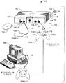
図1は、例示的なマルチシステムゲーム環境100を示し、2つのタイプのホストゲームシステム、すなわちゲームコンソール102およびパーソナルコンピュータ(PC)104が示されている。周辺ゲームコントローラ106(1)および106(2)は、ホストゲームシステム102および104に接続されて、プレーヤとビデオゲームの対話を容易にする。
FIG. 1 illustrates an exemplary
各コントローラ106は、ホストゲームシステムに有線または無線インターフェースを介して結合される。有線操作では、コントローラ106は、ケーブル108を介してホストゲームシステムに接続される。コントローラは、接続中、ケーブル108を介してホストゲームシステムから電力を得る。無線操作では、コントローラは無線リンクを介してホストゲームシステムに接続され、電池などコントローラ自体の電源から電力を得る。無線リンクは、たとえば赤外線、Bluetooth、またはRF技術を含む任意の多様な技術を使用して実装することができる。ケーブル108は、任意選択でコントローラから取り外して、動作のより大きい自由を提供することができる。
Each
図で示した構成では、ゲームコンソール102は、その前面に4つのスロット110を有しており、4つまでのコントローラ106をサポートすることができるが、スロットの数および配置は修正することができる。有線操作では、ゲームコントローラ106にはビデオゲームの様々な特性/機能を制御するための物理スロット110が割り当てられる。無線操作では、ゲームコントローラ106には仮想スロットが割り当てられる。PC104は、1つまたは複数のコントローラ106をサポートし、コントローラ106は、(図で示したように)ケーブル108を介してUSBポートに、または無線リンクを介して接続することができる。
In the illustrated configuration, the
ホストゲームシステム102と104はどちらもUSBプロトコルをサポートする。しかし、実にUSB規格の範囲内でも、1つのタイプのシステムでプレイするように構成されたコントローラが他のタイプのシステムでのプレイに使用できない程度に異なる動作パラメータが存在することがある。たとえば、PC104は、最高速USBモード(たとえば、480Mb/sまでのデータ転送速度を指定するUSB2.0)をサポートするように構成することができ、ゲームコンソール102は、低速USBモード(たとえば、12Mb/s以下のデータ転送速度を指定するUSB1.1またはその変形形態)をサポートするように構成することができる。
Both
本明細書に説明するように、同じコントローラ106が、ゲームコンソール102とPC104の両方を含む様々なタイプのホストゲームシステムで使用されるように設計される。1つのコントローラ106(1)が、ゲームコンソール102またはPC104に交互に関連付けられるものとして図示してある。ゲームコンソール102と関連する場合は、(破線で示した)コントローラ106(1)は、第1のUSBモード(たとえば低速USB1.1)で、ゲームコンソール102によってサポートされる第1の組の動作パラメータで動作する。PC104と関連する場合は、(実線で示した)コントローラ106(1)は、第2のUSBモード(たとえば最高速USB2.0または高速USB2.0)で、PC104によってサポートされる第2の組の動作パラメータで動作する。
As described herein, the
プレーヤは、自分のコントローラ106(1)を1つのシステムから別のシステムに単にコントローラを1つのシステム(たとえばゲームコンソール102)から接続を断ち、他のシステム(たとえばPC104)に再接続することによって移すことができる。1つのシステムから接続を断つことは、ケーブル108を物理的に抜き、または無線セッションを終了することによって行われる。別のシステムへの再接続は、ケーブル108を新規のゲームポートまたはUSBポートに物理的に接続し、または発見および結合プロセスを実行して無線セッションを確立することによって行われる。再接続後、コントローラはどのタイプのゲームシステムが通信を試み、適切なUSBモードを確立したかを自動的に判定する。
A player moves his controller 106 (1) from one system to another by simply disconnecting the controller from one system (eg, game console 102) and reconnecting to another system (eg, PC 104). be able to. Disconnecting from one system is done by physically disconnecting the
各コントローラ106は、多様なユーザ対話機構の任意のものを装備することができる。図1で示したように、各コントローラ106は、2つのサムスティック(thumbstick)112(1)および112(2)、方向パッドまたはDパッド114、表面ボタン(surface buttons)116、および2つのトリガ118を装備している。こうした機構は単に代表的なものであって、他の周知のゲーム機構(たとえば肩ボタン(shoulder buttons))を図1で示したものと置き換え、かつ/または追加してもよい。
Each
ゲームコンソール102は、携帯用メディアドライブ120および任意選択の内蔵ハードディスクドライブを装備している。携帯用メディアドライブは、光記憶ディスク122で表される多様な形態の携帯用記憶媒体をサポートする。好適な携帯用記憶媒体の例には、DVD、CD−ROM、ゲームディスク、ゲームカートリッジなどが含まれる。
The
ゲームコンソール102は、A/Vインターフェーシングケーブル124を介してテレビまたは他のディスプレイ(図示せず)に接続される。電力ケーブル126はゲームコンソールに電力を供給する。ゲームコンソール102は、ローカルエリアネットワーク(LAN)またはインターネットなどネットワークへのアクセスを容易にするためのケーブルまたはモデムコネクタ128で表される内部または外部に追加されたネットワーク機能をさらに装備することができる。(図で示したように)メモリユニット(MU)130をコントローラ106内に挿入して、追加の携帯用記憶装置を提供し、または代替としてゲームコンソール102内に挿入することもできる。携帯用メモリユニットは、ユーザがゲームパラメータを格納し、それらをプレイ用に他のコンソールに移送することができるようにする。
The
ゲームコンソール102
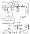
図2は、ゲームコンソール102の機能コンポーネントをより詳細に示す。ゲームコンソール102は、中央処理装置(CPU)200と、フラッシュROM(Read Only Memory)204、RAM(Random Access Memory)206、ハードディスクドライブ208、および携帯用メディアドライブ120を含む様々なタイプのメモリへのプロセッサのアクセスを容易にするメモリコントローラ202を有する。CPU200は、レベル1キャッシュ210およびレベル2キャッシュ212を装備して、データを一時的に格納し、それによってメモリアクセスサイクルの数を減らして処理速度および処理能力を向上させる。
FIG. 2 shows the functional components of the
CPU200、メモリコントローラ202、および様々なメモリデバイスは、シリアルバスおよびパラレルバス、メモリバス、周辺バス、並びに多様なバスアーキテクチャの任意のものを使用するプロセッサバスまたはローカルバスを含む1つまたは複数のバスを介して相互接続される。一例として、こうしたアーキテクチャには、ISA(Industry Standard Architecture)バス、MCA(Micro Channel Architecture)バス、EISA(Enhanced ISA)バス、VESA(Video Electronics Standards Association)ローカルバス、およびPCI(Peripheral Component Interconnect)バスが含まれる。
適切な一実施例として、CPU200、メモリコントローラ202、ROM204、およびRAM206は共通のモジュール214に統合される。この実施例では、ROM204は、PCI(Peripheral Component Interconnect)バスおよびROMバス(どちらも図示せず)を介してメモリコントローラ202に接続されたフラッシュROMとして構成される。RAM206は、別々のバス(図示せず)を介してメモリコントローラ202によって独立して制御される複数のDDR SDRAM(Double Data Rate Synchronous Dynamic RAM)モジュールとして構成される。ハードディスクドライブ208および携帯用メディアドライブ120は、バス216(たとえばPCIバス、ATAバス)を介してメモリコントローラに接続される。
As a suitable embodiment, the
3次元グラフィックス処理装置220およびビデオエンコーダ222は、高速かつ高解像度グラフィックス処理用ビデオ処理パイプラインを形成する。データは、グラフィックス処理装置220からディジタルビデオバス(図示せず)を介してビデオエンコーダ222に転送される。オーディオ処理装置224およびオーディオコーデック(コーダ/デコーダ)226は、高忠実度およびステレオ処理を有する対応するオーディオ処理パイプラインを形成する。オーディオデータは、オーディオ処理装置224とオーディオコーデック226の間で通信リンク(図示せず)を介して転送される。ビデオおよびオーディオ処理パイプラインは、データをA/V(オーディオ/ビデオ)ポート228に出力してテレビまたは他のディスプレイに伝送する。図で示した実施例では、ビデオおよびオーディオ処理コンポーネント220〜228は、モジュール214に実装される。
The three-dimensional
USBホストコントローラ230およびネットワークインターフェース232もモジュール214に実装される。ネットワークインターフェース232は、ネットワーク(たとえば、LAN、インターネットなど)へのアクセスを提供し、Ethernet(登録商標)カード、モデム、Bluetoothモジュール、ケーブルモデムなどを含む広範な任意の有線または無線インターフェースコンポーネントの任意のものでもよい。USBホストコントローラ230は、バス(たとえばPCIバス)を介してCPU200およびメモリコントローラ202に結合され、周辺ゲームコントローラ106(1)〜106(4)のホストとして働く。
A
一実施例では、USBホストコントローラ230は、比較的遅いクロック速度(すなわち12Mb/s未満)を除いて、USB1.1低レベル電気信号(low level electrical signaling)および低レベルプロトコルに従う。クロック速度の一例は、約3Mb/sである。減速したデータ転送速度は、EMI放射を低減する助けをする。コンソール102は、この遅いクロック速度によって低速USBで動作するといえる。この低速USBは1つの可能なUSBモードの典型であるが、データ転送速度の他にUSBモードを他の動作パラメータによって規定することができる。
In one embodiment,
ゲームコンソール102は、2つの二重コントローラサポートサブアセンブリ240(1)および240(2)を有し、各サブアセンブリは、2つまでのゲームコントローラ106(1)〜106(4)およびコントローラ無線インターフェース242をサポートする。無線インターフェース242は、たとえばIR、Bluetooth、およびRF技術を含む多様な技術の任意のものを使用することができる。フロントパネルI/Oサブアセンブリ244は、制御ボタン、LED(発光ダイオード)、またはゲームコンソールの外面上に露出された他のインディケータの機能をサポートする。サブアセンブリ240(1)、240(2)、並びに244、およびコントローラ無線インターフェース242は、1つまたは複数のケーブルアセンブリ246を介してモジュール214に、具体的にはUSBコントローラ230に結合される。
The
ゲームコントローラは、サブアセンブリ240および/または無線インターフェース242を介してUSBホストコントローラ230と通信する。コンソール102用のUSB構成の一特徴は、事前定義された固有のアドレスを各ポートに永遠に割り当てることができることである。そのポートに接続されたコントローラは、ポートに割り当てられたアドレスをそのUSBアドレスとして使用する。これによって、コントローラはホストコンソールからの要求に応じて、コントローラ情報を全て含む1つの記述子を単に返せばよいという点で、デバイスのエニュメレーションプロセスが簡単になる。他の特徴は、ルートハブがトラフィックをそのポート全てにブロードキャストせずに、コンソールがポートに接続されたコントローラへの通信を試みている場合にその1つのポートを使用可能にすることである。このポートは、そのデバイスにトラフィックが存在しない場合は使用不可能である。
The game controller communicates with the
USBインターフェース信号は、以下の通りである。 The USB interface signals are as follows.

コントローラ106がコンソール102に接続されている場合、USBホストコントローラ230はコントローラがそれ自体を確認することを求める要求を送信する。この要求に基づいて、コントローラ106はコンソール102が通信の確立を試みていることを確認することができる。コントローラは、適切な低速USBモードに切替えてコンソール102との通信をサポートする。
If the
コンソール102は、システム電力供給モジュール250をさらに備えて、電力をゲームシステム100のコンポーネントおよびゲームコントローラ106に供給する。
The
PC104 PC104
図3は、PC104の機能コンポーネントをより詳細に示す。PC104は、ホストゲームシステムとして動作することができるコンピューティングシステムの単なる一例であることを留意されたい。他の周知のコンピューティングシステムもゲームコントローラ106を使用することができるゲーム環境を提供することができる。こうしたシステムの例には、サーバコンピュータ、シンクライアント、ハンドヘルドまたはラップトップデバイス、マルチプロセッサシステム、マイクロプロセッサベースのシステム、セットトップボックス、ミニコンピュータ、メインフレームコンピュータなどが含まれる。
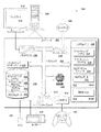
FIG. 3 shows the functional components of the
PC104は、1つまたは複数の処理装置304、システムメモリ306、および様々なシステムコンポーネントを結合するシステムバス308を有する汎用コンピュータ302を備える。システムバス308は、メモリバスまたはメモリコントローラ、周辺バス、アクセラレーテッドグラフィックスポート、および任意の多様なバスアーキテクチャを使用するプロセッサバスまたはローカルバスを含む任意の幾つかのタイプのバス構造のうちの1つまたは複数のものを表す。
The
コンピュータ302は、通常、揮発性および不揮発性メディア、並びにリムーバブルおよびノンリムーバブルメディアを含む多様なコンピュータ可読媒体を備える。図で示した構成では、システムメモリ306は、ランダムアクセスメモリ(RAM)310などの揮発性メモリ、および読み出し専用メモリ(ROM)312などの不揮発性メモリの形態のコンピュータ可読媒体を含む。コンピュータ302内の要素間で情報を転送する助けをする基本ルーチンを含む基本入出力システム(BIOS)314は、ROM312に格納される。RAM310は、通常、処理装置304によって即時にアクセス可能、かつ/または現在操作中のデータおよび/またはプログラムモジュールを含む。
コンピュータ302は、ハードディスクドライブ316、磁気ディスクドライブ318(たとえばフロッピー(登録商標)ディスクドライブ)、および1つまたは複数のデータメディアインターフェース326またはSCSIインターフェース(図示せず)によってシステムバス308に接続された光ディスクドライブ320も有する。ディスクドライブおよびそれと関連するコンピュータ可読媒体は、コンピュータ可読命令、データ構造、プログラムモジュール、およびコンピュータ302のための他のデータの不揮発性記憶を提供する。コンピュータによってアクセス可能なデータを格納することができる他のタイプのコンピュータ可読媒体を使用することもできることに留意されたい。
任意の数のプログラムモジュールをハードディスク316、磁気ディスク318、光ディスク320、ROM312、および/またはRAM310に格納することができる。図で示した実施例では、オペレーティングシステム326、1つまたは複数のアプリケーションプログラム328(たとえばビデオゲーム)、他のプログラムモジュール330、およびプログラムデータ332(たとえばビデオゲームデータ)がハードディスクドライブ316および/またはシステムメモリ306に格納される。
Any number of program modules can be stored in the hard disk 316,
コンピュータ302は、ビデオアダプタ336を介してシステムバス308に接続されたディスプレイ334を備える。ネットワークインターフェース338は、ネットワーク340(たとえば、インターネット、イントラネット、LAN、WANなど)へのアクセスを提供し、入力/出力(I/O)インターフェース342は、マウス344およびキーボード346など周辺デバイスとの通信を可能にする。
The
コンピュータはUSBホストコントローラ348をさらに装備して、ゲームコントローラ106との通信をサポートする。コントローラ106がUSBホスト348に接続された場合、コントローラ106はUSBホストコントローラ348によってサポートされるUSBモードで動作する。一実施例では、USBホストコントローラ348はUSB2.0電気信号およびプロトコルを実装する。USB2.0は、低速USBと比較すると、はるかに速いデータ転送速度(たとえば480Mb/s)を指定する。この高速クロック速度により、PC104は、他の可能なUSBモードの典型である最高速USBモードで動作することができるといえる。あるいは、PC104を高速USBモードで動作するように構成することもできる。
The computer is further equipped with a
コントローラ106がPC104に接続されている場合、USBホストコントローラ348はコントローラがそれ自体を確認することを求める要求を送信する。この要求に基づいて、コントローラ106はコンピュータ302が通信の確立を試みていることを確認することができる。コントローラは、適切な最高速USBモード(あるいは、高速USBモード)に切替えてPC104との通信をサポートする。より具体的には、コントローラ106は、D+/D−ライン(PINS2および3)上で状態を変更し、USB接続を最高速USBモード(または高速USBモード)で動作するようにリセットする。
If the
コントローラ106
図4は、ゲームコントローラ106の機能コンポーネントをより詳細に示す。コントローラ106は、中央処理装置(CPU)402と、ROM404、RAM406、およびEEPROM408を含むメモリを有する。図で示した実施例では、CPU402、ROM404、およびRAM406は、共通のモジュール410上に統合され、1つまたは複数のバス構造を介して相互接続されている。EEPROM408は、モジュール410と分離されているがモジュール410とインターフェースをとっている。
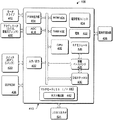
FIG. 4 shows the functional components of the
ゲームコントローラ106は、プレーヤに感触(tactile)フィードバックを提供するモータドライブ412、およびモータドライブ用の制御信号を提供するPWM(パルス幅変調)出力部414を備える。変数入力アクチュエータ416(たとえばサムスティック112およびトリガ118)を介して受信されるプレーヤの動作は、アナログ/ディジタル変換器(ADC)418によってディジタル信号に変換され、CPU402に送信される。ADC418は、たとえば8チャネル10ビットまたは12ビットの変換器として実装することができる。二重状態スイッチ420(たとえばDパッド114およびボタン116)を介して受信されるプレーヤの他の動作は、I/O422を介してCPU402に送信される。
The
ゲームコントローラは、有線または無線操作をサポートすることができる。USBコネクタ424は有線インターフェースを提供するが、RFモジュール426(たとえば2.4GHzのRFモジュール)、無線ベースバンド装置428、およびDMA(Direct Memory Access)チャネル装置430は、無線インターフェースをサポートする。他の実施例では、IR(赤外線)、Bluetooth、UWB(Ultra Wide Band)など代替の無線技術を使用するようにゲームコントローラを設計することができる。ゲームコントローラ106は、電池432などそれ自体の電源を装備して、ゲームコントローラ106の電子モジュールおよびコンポーネントに電力を供給することによって無線操作を可能にする。電源管理ユニット434は、電池寿命を効率よく維持するための管理を提供する。電池充電回路436は、コントローラがケーブルを介してホストゲームシステムに接続された場合に電池432を再充電する。
The game controller can support wired or wireless operation. The
上で述べたように、ゲームコントローラ106は、低速、最高速、および高速USBモードなど様々なUSBモードを使用する様々なホストゲームシステムで使用することができる。ゲームコントローラ106は、ゲームシステムのタイプによって様々なモードの中で切替えを行うマルチモードUSBインターフェース440を備える。USBインターフェース440は、コントローラがどのゲームシステムと通信しようとしているかを判定するホスト検出器442を備える。最初の接触(たとえばケーブルの接続)後に、ホスト検出器442は、ホストゲームシステムからの、コントローラにそれ自体を確認することを求める要求を受信する。ホスト検出器は、その要求を使用して、どのシステムが要求しているかを確認する。ホストシステムが識別された後、USBインターフェース440は適切なUSBモードに切替える。一例では、USBインターフェース440は、コントローラがコンソール102に接続された場合は低速USBモードに、コントローラがPC104に接続された場合は最高速USBモード(または高速USBモード)に切替える。USBモードの切替えは最初の接触または始動時に発生すると説明したが、始動後しばらく経ってから切替えを行うようにコントローラ106を構成してもよいことに留意されたい。
As noted above, the
USBモード切替操作 USB mode switching operation
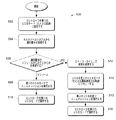
図5は、コントローラが接続されているホストゲームシステムに基づいてコントローラ106に適したUSBモードを選択するプロセス500を示す。プロセス500は、ハードウェア、ソフトウェア、またはその組合せで実装することができる動作シーケンスを示す論理フローグラフにおけるブロックの一群として示してある。ソフトウェアのコンテキストでは、ブロックは、1つまたは複数のプロセッサによって実行される場合に、列挙された動作を実行するコンピュータ命令を表す。
FIG. 5 shows a
このプロセスには、ホストゲームシステムとの最初の対話中にゲームコントローラによって実行される動作が含まれる。論述の目的で、図1〜4に関して上記に記載したコントローラ106、ゲームコンソール102、およびPC104を参照して、プロセス500を説明する。このプロセス500は、有線および/または無線通信用に設計された他のタイプのコントローラ、および他のタイプのホストゲームシステムで実行することもできることに留意されたい。
This process includes operations performed by the game controller during the initial interaction with the host game system. For discussion purposes,
ブロック502で、ゲームコントローラ106は、最初に第1のUSBモードに設定される。一例として、ゲームコントローラ106は、最初に低速USBモードで動作するように規定値が設定される。プレーヤがコントローラ106をホストゲームシステムに接続すると、コントローラ106はそのD+ラインをハイにプルして、デバイスが接続されたことをコンソールに通知する。ゲームコントローラ106は、次いでホストゲームシステムから、それ自体を確認することを求める要求を受信する(ブロック504)。
At
ブロック506で、ゲームコントローラ106は、識別要求がゲームコンソール102から発信されたものか、またはPC104から発信されたものかを判定する。要求がゲームコンソール102からの場合(すなわちブロック506からの「コンソール」分岐)、ゲームコントローラ106は、すでに第1のUSBモードに事前設定されており、したがって、ゲームコンソール102は第1のUSBモードの動作パラメータを使用してUSB接続を確立するためのエニュメレーションを開始することができる(ブロック508)。エニュメレーションプロセスの一部として、コントローラは記述子をコンソールに送信する。この記述子には、ID、デバイスクラス、デバイスタイプ、エンドポイントアドレスなどのデバイス情報が含まれる。接続が確立された後、コントローラは、コンソール102上で実行されているビデオゲームとプレーヤの対話を容易にする第1のUSBモードで操作される(ブロック510)。
At
一方、ゲームコントローラが、識別要求がPC104からであると判定した場合(すなわちブロック506からの「PC」分岐)、コントローラ510はD+/D−ライン上で状態の変更を行い(ブロック512)、最高速USBまたは高速USBなど第2のUSBモードで動作するようにUSB接続をリセットする(ブロック514)。ゲームコンソール102は、USBエニュメレーションを実行し、第2のUSBモードの動作パラメータを使用してUSB接続を確立する(ブロック516)。次いで、コントローラは、PC104上で実行されているビデオゲームとプレーヤの対話を容易にする第2のUSBモードで操作されることができる(ブロック518)。
On the other hand, if the game controller determines that the identification request is from the PC 104 (ie, the “PC” branch from block 506), the
USBモード間の切替えは最初の始動時に発生すると記載したが、始動後しばらく経ってから切替えを行うこともできる。 Although it has been described that the switching between the USB modes occurs at the time of initial startup, the switching can be performed after a while after the startup.
結論 Conclusion
上述のコントローラは、様々なUSB(Uniform Serial Bus)モードで動作することができ、様々なタイプのホストゲームシステムで使用することができるようになされている。本発明を構造的特徴かつ/または方法論的動作に特有の専門用語で説明したが、理解されるように、添付の特許請求の範囲で定義される本発明は、説明した特定の特徴または動作に必ずしも限定されない。むしろ特定の特徴および動作は、特許請求する本発明を実施する例示的な形態として開示したものである。 The above-described controller can operate in various USB (Uniform Serial Bus) modes and can be used in various types of host game systems. Although the invention has been described in terminology specific to structural features and / or methodological operations, it should be understood that the invention as defined by the appended claims covers the specific features or operations described. It is not necessarily limited. Rather, the specific features and acts are disclosed as exemplary forms of implementing the claimed invention.
102 ゲームコンソール
106(1)、106(2)、106(3)、106(4) コントローラ
120 携帯用メディアドライブ
200 中央処理装置
202 メモリコントローラ 204 フラッシュROMメモリ
206 RAMメモリ
208 ハードディスクドライブ
210 レベル1キャッシュ
212 レベル2キャッシュ
216 ATAケーブル
220 3次元グラフィックス処理装置
222 ビデオエンコーダ
224 オーディオ処理装置
226 オーディオコーデック
228 A/Vポート
230 USBホストコントローラ
240(1)、240(2) 二重コントローラポートサブアセンブリ
242 コントローラ無線I/F
244 フロントパネルI/Oサブアセンブリ
250 システム電力供給モジュール
302 コンピュータ
304 処理装置
306 システムメモリ
308 システムバス
334 ディスプレイ
336 ビデオアダプタ
338 ネットワークI/F
340 ネットワーク
342 I/0インターフェース
344 マウス
346 キーボード
348 USBホスト
412 モータドライブ
414 PWM出力部
416 アクチュエータ(トリガ、サムスティック)
420 スイッチ(ボタン、Dパッド)
422 入力/出力
424 USBコネクタ
426 RFモジュール
428 無線ベースバンド
430 DMAチャネル
432 電池
434 電源管理ユニット
436 電池充電回路
440 マルチモードUSB I/F
442 ホスト検出器
102 Game console 106 (1), 106 (2), 106 (3), 106 (4)
244 Front panel I /
340 Network 342 I /
420 switch (button, D pad)
422 Input /
442 Host detector
Claims (24)
様々なホストゲームシステムとの通信を容易にする通信インターフェースと、
第1のホストゲームシステムとの通信中は第1のUSBモードを使用し、第2のホストゲームシステムとの通信中は第2のUSBモードを使用するUSBプロトコルモジュールとを備えることを特徴とするマルチシステムビデオゲームコントローラ。 A multi-system video game controller for use with various host game systems supporting various USB modes,
A communication interface that facilitates communication with various host game systems;
And a USB protocol module that uses the first USB mode during communication with the first host game system and uses the second USB mode during communication with the second host game system. Multi-system video game controller.
前記プロセッサに動作可能に結合されたメモリと、
前記プロセッサに動作可能に結合され、ビデオゲームコントローラが第1のホストゲームシステムに接続されている場合は第1のUSBモードでの通信を容易にし、前記ビデオゲームコントローラが第2のホストゲームシステムに接続されている場合は第2のUSBモードでの通信を容易にするUSBモジュールとを備えることを特徴とするビデオゲームコントローラ。 A processor;
A memory operably coupled to the processor;
When operatively coupled to the processor and a video game controller is connected to the first host game system, communication in a first USB mode is facilitated, and the video game controller is connected to the second host game system. A video game controller comprising: a USB module that facilitates communication in the second USB mode when connected.
前記プロセッサ、前記メモリ、および前記無線モジュールに電力を供給する電源とをさらに備えることを特徴とする請求項7に記載のビデオゲームコントローラ。 A wireless module that supports wireless communication;
The video game controller of claim 7, further comprising a power source that supplies power to the processor, the memory, and the wireless module.
前記ビデオゲームコントローラが前記第1のホストゲームシステムに接続されている場合は通信用に第1のUSBモードを使用し、前記ビデオゲームコントローラが前記第2のホストゲームシステムに接続されている場合は通信用に第2のUSBモードを使用する手段とを備えることを特徴とするビデオゲームコントローラ。 Means for determining which of the first host game system or the second host game system is establishing a USB connection with the video game controller;
When the video game controller is connected to the first host game system, the first USB mode is used for communication, and when the video game controller is connected to the second host game system. And a means for using the second USB mode for communication.
前記ビデオゲームコントローラが前記第1のホストゲームシステムと通信するために接続されている場合は、前記ビデオゲームコントローラを第1のUSBモードで操作すること、および
前記ビデオゲームコントローラが前記第2のホストゲームシステムと通信するために接続されている場合は、前記ビデオゲームコントローラを第2のUSBモードで操作することを備えることを特徴とする方法。 Determining at a video game controller whether the video game controller is operatively connected to communicate with a first host game system or a second host game system;
Operating the video game controller in a first USB mode when the video game controller is connected to communicate with the first host game system; and A method comprising operating the video game controller in a second USB mode when connected to communicate with a game system.
最初の接続中に前記ビデオゲームコントローラを識別する要求を受信すること、および
前記要求に基づいて前記ビデオゲームコントローラが前記第1または第2のホストゲームシステムのどちらに接続されているかを確認することを含むことを特徴とする請求項19に記載の方法。 The determination is
Receiving a request to identify the video game controller during an initial connection, and determining whether the video game controller is connected to the first or second host game system based on the request 20. The method of claim 19, comprising:
前記ビデオゲームコントローラが前記第2のホストゲームシステムと通信するために接続されていると判定された後、前記ビデオゲームコントローラを前記第2のUSBモードに自動的にリセットすることをさらに備えることを特徴とする請求項19に記載の方法。 After setting the video game controller to the first USB mode and determining that the video game controller is connected to communicate with the second host game system, the video game controller is The method of claim 19, further comprising automatically resetting to the second USB mode.
Applications Claiming Priority (1)
| Application Number | Priority Date | Filing Date | Title |
|---|---|---|---|
| US10/816,800 US20050221894A1 (en) | 2004-03-31 | 2004-03-31 | Multi-system game controller that operates in multiple USB modes |
Publications (2)
| Publication Number | Publication Date |
|---|---|
| JP2005293581A true JP2005293581A (en) | 2005-10-20 |
| JP2005293581A5 JP2005293581A5 (en) | 2008-05-15 |
Family
ID=34887772
Family Applications (1)
| Application Number | Title | Priority Date | Filing Date |
|---|---|---|---|
| JP2005094740A Pending JP2005293581A (en) | 2004-03-31 | 2005-03-29 | Multi-system game controller that operates in multiple usb modes |
Country Status (8)
| Country | Link |
|---|---|
| US (1) | US20050221894A1 (en) |
| EP (1) | EP1582241A1 (en) |
| JP (1) | JP2005293581A (en) |
| KR (1) | KR20060044993A (en) |
| CN (1) | CN1677378A (en) |
| AU (1) | AU2005201190A1 (en) |
| CA (1) | CA2502968A1 (en) |
| TW (1) | TW200537356A (en) |
Cited By (2)
| Publication number | Priority date | Publication date | Assignee | Title |
|---|---|---|---|---|
| JP2007318855A (en) * | 2006-05-24 | 2007-12-06 | Sony Computer Entertainment Inc | Terminal device |
| JP2022504761A (en) * | 2019-09-24 | 2022-01-13 | シャンハイ センスタイム リンガン インテリジェント テクノロジー カンパニー リミテッド | Equipment control method, equipment, storage medium |
Families Citing this family (39)
| Publication number | Priority date | Publication date | Assignee | Title |
|---|---|---|---|---|
| MY115236A (en) | 1996-03-28 | 2003-04-30 | Shell Int Research | Method for monitoring well cementing operations |
| US6125935A (en) * | 1996-03-28 | 2000-10-03 | Shell Oil Company | Method for monitoring well cementing operations |
| US7685328B2 (en) * | 2004-09-09 | 2010-03-23 | Stmicroelectronics, Inc. | Generic universal serial bus device operable at low and full speed and adapted for use in a smart card device |
| EP1834127A4 (en) * | 2005-01-04 | 2012-08-15 | Coactive Drive Corp | Vibration device |
| JP4849829B2 (en) * | 2005-05-15 | 2012-01-11 | 株式会社ソニー・コンピュータエンタテインメント | Center device |
| US9459632B2 (en) | 2005-06-27 | 2016-10-04 | Coactive Drive Corporation | Synchronized array of vibration actuators in a network topology |
| EP2380640A3 (en) * | 2005-06-27 | 2011-12-28 | Coactive Drive Corporation | Synchronized vibration device for haptic feedback |
| US9764357B2 (en) | 2005-06-27 | 2017-09-19 | General Vibration Corporation | Synchronized array of vibration actuators in an integrated module |
| US11203041B2 (en) | 2005-06-27 | 2021-12-21 | General Vibration Corporation | Haptic game controller with dual linear vibration actuators |
| CN2825037Y (en) * | 2005-10-26 | 2006-10-11 | 陈霄东 | Mobile phone game controller |
| KR100791292B1 (en) * | 2006-02-22 | 2008-01-04 | 삼성전자주식회사 | Multiple access remote control device |
| JP5089060B2 (en) * | 2006-03-14 | 2012-12-05 | 株式会社ソニー・コンピュータエンタテインメント | Entertainment system and game controller |
| CN100437541C (en) * | 2006-03-28 | 2008-11-26 | 华为技术有限公司 | A Realization Method of Serial Peripheral Interface |
| TWI395603B (en) * | 2006-04-26 | 2013-05-11 | 原相科技股份有限公司 | Interactive game device and game controller thereof |
| WO2007137446A1 (en) * | 2006-05-29 | 2007-12-06 | Fangen Xiong | Interface device component for computer game |
| US8079905B2 (en) | 2006-11-06 | 2011-12-20 | Igt | Remote wager gaming system using a video game console |
| PL2130108T3 (en) * | 2007-03-29 | 2018-07-31 | Nokia Technologies Oy | Connection to a usb device |
| US20080248882A1 (en) * | 2007-04-03 | 2008-10-09 | Hsu Kent T J | Video game console adapter |
| US20080299906A1 (en) * | 2007-06-04 | 2008-12-04 | Topway Electrical Appliance Company | Emulating playing apparatus of simulating games |
| US8661164B2 (en) * | 2010-08-24 | 2014-02-25 | Mediatek Inc. | Method of USB device enumeration including detecting the operating system type of the USB host |
| EP2686941A4 (en) | 2011-03-17 | 2014-12-03 | Coactive Drive Corp | Asymmetric and general vibration waveforms from multiple synchronized vibration actuators |
| US9619417B2 (en) | 2011-06-17 | 2017-04-11 | Alcatel Lucent | Method and apparatus for remote delivery of managed USB services via a mobile computing device |
| WO2013157053A1 (en) * | 2012-04-20 | 2013-10-24 | 任天堂株式会社 | Game system and game controller |
| TWI486000B (en) * | 2013-03-20 | 2015-05-21 | Realtek Semiconductor Corp | Network apparatus and connection detecting method thereof |
| CN104079415B (en) * | 2013-03-27 | 2018-04-10 | 瑞昱半导体股份有限公司 | Network device and connection detection method thereof |
| CN104102603B (en) * | 2013-04-09 | 2017-03-29 | 瑞昱半导体股份有限公司 | Universal serial bus network interface controller and its operation mode switching method |
| US10318013B1 (en) * | 2015-04-01 | 2019-06-11 | Bansen Labs LLC | System and method for converting input from alternate input devices |
| US10346334B2 (en) * | 2016-06-09 | 2019-07-09 | Plantronics, Inc. | Mode switchable audio processor for digital audio |
| US10542120B2 (en) | 2016-11-10 | 2020-01-21 | Microsoft Technology Licensing, Llc | Wirelessly providing operating system specific features |
| CN108132899A (en) * | 2016-12-01 | 2018-06-08 | 中兴通讯股份有限公司 | A kind of transmission mode configuration method, apparatus and system |
| CN109381856A (en) * | 2018-09-12 | 2019-02-26 | 深圳闪电鸟网络科技有限公司 | Device, method, electronic equipment and the storage medium that game host is controlled |
| JP7386012B2 (en) * | 2019-07-30 | 2023-11-24 | 株式会社ワコム | Information input device, method, and program |
| TWI741764B (en) * | 2020-08-28 | 2021-10-01 | 孕龍科技股份有限公司 | Game Controller |
| CN115114214B (en) * | 2021-03-18 | 2024-09-03 | 广州视源电子科技股份有限公司 | Multi-system integrated machine, file sharing method and storage medium |
| CN117012017B (en) * | 2022-04-29 | 2026-01-27 | 腾讯科技(深圳)有限公司 | Data transmission method, device, equipment and medium |
| US12074946B2 (en) | 2022-11-04 | 2024-08-27 | Backbone Labs, Inc. | System and method for automatic content capability detection |
| US12324983B2 (en) | 2022-12-23 | 2025-06-10 | Backbone Labs, Inc. | Universal mobile game controller |
| US12558612B2 (en) | 2022-12-23 | 2026-02-24 | Backbone Labs, Inc. | Universal mobile game controller |
| US12427403B2 (en) | 2023-07-27 | 2025-09-30 | Backbone Labs, Inc. | Mobile game controller and method for connecting to a wireless audio device |
Citations (3)
| Publication number | Priority date | Publication date | Assignee | Title |
|---|---|---|---|---|
| JPH06205073A (en) * | 1991-06-20 | 1994-07-22 | Futaba Corp | Automatic detector for communication speed |
| JP2000231403A (en) * | 1999-02-09 | 2000-08-22 | Keyence Corp | Remote input and output system and slave device for the same |
| JP2001222503A (en) * | 2000-02-08 | 2001-08-17 | Ricoh Co Ltd | Peripheral device control system |
Family Cites Families (9)
| Publication number | Priority date | Publication date | Assignee | Title |
|---|---|---|---|---|
| US5935224A (en) * | 1997-04-24 | 1999-08-10 | Microsoft Corporation | Method and apparatus for adaptively coupling an external peripheral device to either a universal serial bus port on a computer or hub or a game port on a computer |
| DE69810292D1 (en) * | 1997-06-18 | 2003-01-30 | Act Labs Ltd | VIDEO GAME CONTROL DEVICE SYSTEM WITH INTERCHANGEABLE INTERFACE ADJUSTMENT ELEMENTS |
| US6020875A (en) * | 1997-10-31 | 2000-02-01 | Immersion Corporation | High fidelity mechanical transmission system and interface device |
| TW387585U (en) * | 1998-05-29 | 2000-04-11 | Wang Ren Je | Universal serial bus converter of personal computer game playing port |
| US6468160B2 (en) * | 1999-04-08 | 2002-10-22 | Nintendo Of America, Inc. | Security system for video game system with hard disk drive and internet access capability |
| US6789989B2 (en) * | 2002-03-13 | 2004-09-14 | Uli Walther | Screw having a head with concave underside |
| US7024501B1 (en) * | 2002-11-18 | 2006-04-04 | Cypress Semiconductor Corp. | Method and apparatus for attaching USB peripherals to host ports |
| US20040152515A1 (en) * | 2003-02-05 | 2004-08-05 | Logitech Europe S.A. | Cordless game controller system |
| US20050096086A1 (en) * | 2003-10-31 | 2005-05-05 | Jaalaa, Inc. | Computer interface with both wired and wireless links |
-
2004
- 2004-03-31 US US10/816,800 patent/US20050221894A1/en not_active Abandoned
-
2005
- 2005-03-18 TW TW094108492A patent/TW200537356A/en unknown
- 2005-03-18 AU AU2005201190A patent/AU2005201190A1/en not_active Abandoned
- 2005-03-23 EP EP05102338A patent/EP1582241A1/en not_active Withdrawn
- 2005-03-29 JP JP2005094740A patent/JP2005293581A/en active Pending
- 2005-03-30 KR KR1020050026392A patent/KR20060044993A/en not_active Withdrawn
- 2005-03-30 CA CA002502968A patent/CA2502968A1/en not_active Abandoned
- 2005-03-31 CN CNA2005100637519A patent/CN1677378A/en active Pending
Patent Citations (3)
| Publication number | Priority date | Publication date | Assignee | Title |
|---|---|---|---|---|
| JPH06205073A (en) * | 1991-06-20 | 1994-07-22 | Futaba Corp | Automatic detector for communication speed |
| JP2000231403A (en) * | 1999-02-09 | 2000-08-22 | Keyence Corp | Remote input and output system and slave device for the same |
| JP2001222503A (en) * | 2000-02-08 | 2001-08-17 | Ricoh Co Ltd | Peripheral device control system |
Cited By (2)
| Publication number | Priority date | Publication date | Assignee | Title |
|---|---|---|---|---|
| JP2007318855A (en) * | 2006-05-24 | 2007-12-06 | Sony Computer Entertainment Inc | Terminal device |
| JP2022504761A (en) * | 2019-09-24 | 2022-01-13 | シャンハイ センスタイム リンガン インテリジェント テクノロジー カンパニー リミテッド | Equipment control method, equipment, storage medium |
Also Published As
| Publication number | Publication date |
|---|---|
| US20050221894A1 (en) | 2005-10-06 |
| EP1582241A1 (en) | 2005-10-05 |
| AU2005201190A1 (en) | 2005-10-20 |
| KR20060044993A (en) | 2006-05-16 |
| CN1677378A (en) | 2005-10-05 |
| TW200537356A (en) | 2005-11-16 |
| CA2502968A1 (en) | 2005-09-30 |
Similar Documents
| Publication | Publication Date | Title |
|---|---|---|
| EP1582241A1 (en) | Multi-system game controller that operates in multiple USB modes | |
| US9427660B2 (en) | Game system that converts between wireless operation and wired operation while communicating with a controller | |
| US9573056B2 (en) | Expandable control device via hardware attachment | |
| EP1681658B1 (en) | Game console notification system | |
| US8882597B2 (en) | Hybrid separable motion controller | |
| US7789741B1 (en) | Squad vs. squad video game | |
| CN1676185B (en) | Game system and method for binding host and game controller therein | |
| US20070111796A1 (en) | Association of peripherals communicatively attached to a console device | |
| WO2014200895A1 (en) | Systems and methods for transmitting data using selected transmission technology from among other transmission technologies | |
| JP2006102490A (en) | Mapping of gamepad controller | |
| CN100592310C (en) | Game controller power management | |
| EP3053634A1 (en) | System for associating a wireless device to a console device | |
| EP1583317A1 (en) | Wireless game controller with fast connect to a host | |
| US12434158B2 (en) | Modular multi-system gaming console | |
| US8376858B2 (en) | System and method for communicating game information between a portable gaming device and a game controller | |
| JP7728397B2 (en) | Information processing device | |
| WO2024127575A1 (en) | Information processing device and game image display method | |
| CN115563042A (en) | Composite game device and composite game device configuration method | |
| Nolan | Control: Playing through Videogame Interface Constraints | |
| KR20060045142A (en) | Game Controller Power Management | |
| HK1187849A (en) | Game console notification system |
Legal Events
| Date | Code | Title | Description |
|---|---|---|---|
| A521 | Request for written amendment filed |
Free format text: JAPANESE INTERMEDIATE CODE: A523 Effective date: 20080331 |
|
| A621 | Written request for application examination |
Free format text: JAPANESE INTERMEDIATE CODE: A621 Effective date: 20080331 |
|
| A977 | Report on retrieval |
Free format text: JAPANESE INTERMEDIATE CODE: A971007 Effective date: 20101125 |
|
| A131 | Notification of reasons for refusal |
Free format text: JAPANESE INTERMEDIATE CODE: A131 Effective date: 20101203 |
|
| A02 | Decision of refusal |
Free format text: JAPANESE INTERMEDIATE CODE: A02 Effective date: 20110426 |