JP2005292831A - Liquid crystal display - Google Patents
Liquid crystal display Download PDFInfo
- Publication number
- JP2005292831A JP2005292831A JP2005098932A JP2005098932A JP2005292831A JP 2005292831 A JP2005292831 A JP 2005292831A JP 2005098932 A JP2005098932 A JP 2005098932A JP 2005098932 A JP2005098932 A JP 2005098932A JP 2005292831 A JP2005292831 A JP 2005292831A
- Authority
- JP
- Japan
- Prior art keywords
- switching element
- liquid crystal
- crystal display
- data
- switching elements
- Prior art date
- Legal status (The legal status is an assumption and is not a legal conclusion. Google has not performed a legal analysis and makes no representation as to the accuracy of the status listed.)
- Pending
Links
Images
Classifications
-
- G—PHYSICS
- G09—EDUCATION; CRYPTOGRAPHY; DISPLAY; ADVERTISING; SEALS
- G09G—ARRANGEMENTS OR CIRCUITS FOR CONTROL OF INDICATING DEVICES USING STATIC MEANS TO PRESENT VARIABLE INFORMATION
- G09G3/00—Control arrangements or circuits, of interest only in connection with visual indicators other than cathode-ray tubes
- G09G3/20—Control arrangements or circuits, of interest only in connection with visual indicators other than cathode-ray tubes for presentation of an assembly of a number of characters, e.g. a page, by composing the assembly by combination of individual elements arranged in a matrix no fixed position being assigned to or needed to be assigned to the individual characters or partial characters
- G09G3/34—Control arrangements or circuits, of interest only in connection with visual indicators other than cathode-ray tubes for presentation of an assembly of a number of characters, e.g. a page, by composing the assembly by combination of individual elements arranged in a matrix no fixed position being assigned to or needed to be assigned to the individual characters or partial characters by control of light from an independent source
- G09G3/36—Control arrangements or circuits, of interest only in connection with visual indicators other than cathode-ray tubes for presentation of an assembly of a number of characters, e.g. a page, by composing the assembly by combination of individual elements arranged in a matrix no fixed position being assigned to or needed to be assigned to the individual characters or partial characters by control of light from an independent source using liquid crystals
- G09G3/3611—Control of matrices with row and column drivers
- G09G3/3614—Control of polarity reversal in general
-
- A—HUMAN NECESSITIES
- A45—HAND OR TRAVELLING ARTICLES
- A45D—HAIRDRESSING OR SHAVING EQUIPMENT; EQUIPMENT FOR COSMETICS OR COSMETIC TREATMENTS, e.g. FOR MANICURING OR PEDICURING
- A45D20/00—Hair drying devices; Accessories therefor
- A45D20/04—Hot-air producers
- A45D20/08—Hot-air producers heated electrically
- A45D20/10—Hand-held drying devices, e.g. air douches
-
- G—PHYSICS
- G09—EDUCATION; CRYPTOGRAPHY; DISPLAY; ADVERTISING; SEALS
- G09G—ARRANGEMENTS OR CIRCUITS FOR CONTROL OF INDICATING DEVICES USING STATIC MEANS TO PRESENT VARIABLE INFORMATION
- G09G3/00—Control arrangements or circuits, of interest only in connection with visual indicators other than cathode-ray tubes
- G09G3/20—Control arrangements or circuits, of interest only in connection with visual indicators other than cathode-ray tubes for presentation of an assembly of a number of characters, e.g. a page, by composing the assembly by combination of individual elements arranged in a matrix no fixed position being assigned to or needed to be assigned to the individual characters or partial characters
- G09G3/34—Control arrangements or circuits, of interest only in connection with visual indicators other than cathode-ray tubes for presentation of an assembly of a number of characters, e.g. a page, by composing the assembly by combination of individual elements arranged in a matrix no fixed position being assigned to or needed to be assigned to the individual characters or partial characters by control of light from an independent source
- G09G3/36—Control arrangements or circuits, of interest only in connection with visual indicators other than cathode-ray tubes for presentation of an assembly of a number of characters, e.g. a page, by composing the assembly by combination of individual elements arranged in a matrix no fixed position being assigned to or needed to be assigned to the individual characters or partial characters by control of light from an independent source using liquid crystals
- G09G3/3611—Control of matrices with row and column drivers
- G09G3/3648—Control of matrices with row and column drivers using an active matrix
- G09G3/3659—Control of matrices with row and column drivers using an active matrix the addressing of the pixel involving the control of two or more scan electrodes or two or more data electrodes, e.g. pixel voltage dependant on signal of two data electrodes
-
- H—ELECTRICITY
- H01—ELECTRIC ELEMENTS
- H01T—SPARK GAPS; OVERVOLTAGE ARRESTERS USING SPARK GAPS; SPARKING PLUGS; CORONA DEVICES; GENERATING IONS TO BE INTRODUCED INTO NON-ENCLOSED GASES
- H01T23/00—Apparatus for generating ions to be introduced into non-enclosed gases, e.g. into the atmosphere
-
- H—ELECTRICITY
- H05—ELECTRIC TECHNIQUES NOT OTHERWISE PROVIDED FOR
- H05B—ELECTRIC HEATING; ELECTRIC LIGHT SOURCES NOT OTHERWISE PROVIDED FOR; CIRCUIT ARRANGEMENTS FOR ELECTRIC LIGHT SOURCES, IN GENERAL
- H05B3/00—Ohmic-resistance heating
- H05B3/40—Heating elements having the shape of rods or tubes
- H05B3/54—Heating elements having the shape of rods or tubes flexible
- H05B3/56—Heating cables
-
- G—PHYSICS
- G09—EDUCATION; CRYPTOGRAPHY; DISPLAY; ADVERTISING; SEALS
- G09G—ARRANGEMENTS OR CIRCUITS FOR CONTROL OF INDICATING DEVICES USING STATIC MEANS TO PRESENT VARIABLE INFORMATION
- G09G2300/00—Aspects of the constitution of display devices
- G09G2300/08—Active matrix structure, i.e. with use of active elements, inclusive of non-linear two terminal elements, in the pixels together with light emitting or modulating elements
- G09G2300/0809—Several active elements per pixel in active matrix panels
-
- G—PHYSICS
- G09—EDUCATION; CRYPTOGRAPHY; DISPLAY; ADVERTISING; SEALS
- G09G—ARRANGEMENTS OR CIRCUITS FOR CONTROL OF INDICATING DEVICES USING STATIC MEANS TO PRESENT VARIABLE INFORMATION
- G09G2320/00—Control of display operating conditions
- G09G2320/02—Improving the quality of display appearance
- G09G2320/0209—Crosstalk reduction, i.e. to reduce direct or indirect influences of signals directed to a certain pixel of the displayed image on other pixels of said image, inclusive of influences affecting pixels in different frames or fields or sub-images which constitute a same image, e.g. left and right images of a stereoscopic display
Landscapes
- Engineering & Computer Science (AREA)
- Chemical & Material Sciences (AREA)
- Crystallography & Structural Chemistry (AREA)
- Physics & Mathematics (AREA)
- Computer Hardware Design (AREA)
- General Physics & Mathematics (AREA)
- Theoretical Computer Science (AREA)
- Liquid Crystal (AREA)
- Control Of Indicators Other Than Cathode Ray Tubes (AREA)
- Liquid Crystal Display Device Control (AREA)
- Devices For Indicating Variable Information By Combining Individual Elements (AREA)
Abstract
Description
本発明は液晶表示装置に関し、特に反転駆動液晶表示装置に関する。 The present invention relates to a liquid crystal display device, and more particularly to an inversion driving liquid crystal display device.
一般的な液晶表示装置は、画素電極及び共通電極が備えられた二つの表示板と、その間に注入されている誘電率異方性を有する液晶層と、を含む。画素電極は行列状に配列されており、薄膜トランジスタ(TFT)などのスイッチング素子に連結されて一行ずつ順にデータ電圧の印加を受ける。共通電極は表示板の全面にかけて形成されており、共通電圧の印加を受ける。画素電極、共通電極及びその間の液晶層は、回路的に見ると液晶キャパシタをなしている。液晶キャパシタは、これに連結されたスイッチング素子と共に画素を構成する基本単位となる。 A general liquid crystal display device includes two display panels provided with a pixel electrode and a common electrode, and a liquid crystal layer having dielectric anisotropy injected therebetween. The pixel electrodes are arranged in a matrix, and are connected to a switching element such as a thin film transistor (TFT) to receive a data voltage applied in order row by row. The common electrode is formed over the entire surface of the display panel and receives a common voltage. The pixel electrode, the common electrode, and the liquid crystal layer therebetween constitute a liquid crystal capacitor in terms of a circuit. The liquid crystal capacitor is a basic unit constituting a pixel together with a switching element connected thereto.
このような液晶表示装置では、二つの電極に電圧を印加して液晶層に電界を生成し、この電界の強さを調節して液晶層を通過する光の透過率を調節することによって、所望の画像を表示する。この時、液晶層に一方向の電圧が長時間印加されることによって発生する劣化現象を防止するために、フレーム別、行別、または画素別に共通電圧に対するデータ電圧の極性を反転させる。 In such a liquid crystal display device, a voltage is applied to two electrodes to generate an electric field in the liquid crystal layer, and the intensity of this electric field is adjusted to adjust the transmittance of light passing through the liquid crystal layer, thereby obtaining a desired value. The image of is displayed. At this time, the polarity of the data voltage with respect to the common voltage is inverted for each frame, each row, or each pixel in order to prevent a deterioration phenomenon caused by applying a unidirectional voltage to the liquid crystal layer for a long time.
このようにデータ電圧の極性を反転させる方式の中でも、画素別にデータ電圧の極性を反転させる方式では(以下、“ドット反転”とする)、キックバック電圧による垂直フリッカー現象や垂直クロストーク現象などが減少して、画質が向上する。しかし、所定の行及び所定の列ごとにデータ電圧の極性を反転させなければならないので、データ線へのデータ電圧の印加動作が複雑になって、データ線の信号遅延による問題が深刻化する。したがって、信号遅延を減少させるために低抵抗物質でデータ線を形成したりするため、製造工程が複雑になり製造コストが高くついてしまう。 Among the methods for inverting the polarity of the data voltage in this way, the method for inverting the polarity of the data voltage for each pixel (hereinafter referred to as “dot inversion”) causes vertical flicker phenomenon or vertical crosstalk phenomenon due to kickback voltage. Decrease and improve image quality. However, since the polarity of the data voltage must be inverted every predetermined row and predetermined column, the operation of applying the data voltage to the data line becomes complicated, and the problem due to the signal delay of the data line becomes serious. Therefore, a data line is formed with a low-resistance material in order to reduce signal delay, which complicates the manufacturing process and increases the manufacturing cost.
一方、所定の列ごとにデータ電圧の極性を反転させる方式では(以下、“列反転”とする)、一つのデータ線を通じて流れるデータ電圧の極性はフレーム別に反転するので、データ線の信号遅延の問題は大幅に減少する。しかし、列反転は、垂直フリッカー現象及び垂直クロストーク現象などが生じて、液晶表示装置の画質が悪化する。 On the other hand, in the method of inverting the polarity of the data voltage for each predetermined column (hereinafter referred to as “column inversion”), the polarity of the data voltage flowing through one data line is inverted for each frame. The problem is greatly reduced. However, the column inversion causes a vertical flicker phenomenon and a vertical crosstalk phenomenon, and the image quality of the liquid crystal display device is deteriorated.
そこで、本発明は、液晶表示装置の画質を向上させることを目的とする。
また、本発明は、列反転の長所及びドット反転の長所を全て有する液晶表示装置を提供することを目的とする。
Therefore, an object of the present invention is to improve the image quality of a liquid crystal display device.
Another object of the present invention is to provide a liquid crystal display device having all the advantages of column inversion and dot inversion.
また、本発明は、液晶表示装置の不良率を減少させ、生産性を向上させることにある。 Another object of the present invention is to reduce the defect rate of liquid crystal display devices and improve productivity.
前記課題を解決するために、発明1は、行列状に配列され、第1スイッチング素子と、第2スイッチング素子と、前記第1及び第2スイッチング素子に連結された画素電極とを各々備えた複数の画素のうち少なくとも一つの画素行を各々含む複数の画素行群と、前記第1及び第2スイッチング素子に連結されており、前記第1及び第2スイッチング素子をオンさせるゲートオン電圧を伝達する複数のゲート線と、前記第1及び第2スイッチング素子に連結されており、データ電圧を伝達する複数のデータ線と、を含み、前記第1及び第2スイッチング素子は互いに異なる前記ゲート線及びデータ線に連結されており、前記画素電極を介して隣接する二つの前記データ線との間には、静電容量が実質的に同一である第1キャパシタ及び第2寄生キャパシタが形成されていることを特徴とする液晶表示装置を提供する。
In order to solve the above-described problem, the
これにより、列反転駆動する場合に、垂直クロストークを大幅に減少させることができる。そのため、液晶表示装置の画質が向上する。また、データ線材料の選択幅が拡大し、製造工程を単純化するのが容易であり、見かけ反転がドット反転であるので、垂直クロストークを減少させ、画質を向上させることができる。さらに、第1スイッチング素子に加えて更に第2スイッチング素子を設けることにより、修理費用を大幅に減少させることができるので、修理工程も単純化される。 As a result, when the column inversion drive is performed, the vertical crosstalk can be greatly reduced. Therefore, the image quality of the liquid crystal display device is improved. In addition, the selection range of the data line material is expanded, the manufacturing process can be easily simplified, and the apparent inversion is dot inversion, so that the vertical crosstalk can be reduced and the image quality can be improved. Further, by providing the second switching element in addition to the first switching element, the repair cost can be greatly reduced, so that the repair process is simplified.
発明2は、前記発明1において、前記第1スイッチング素子を通じて流れる第1リーク電流と前記第2スイッチング素子を通じて流れる第2リーク電流とが実質的に等しくなるように、前記第1及び第2スイッチング素子が配置されていることを特徴とする液晶表示装置を提供する。 A second aspect of the present invention provides the first and second switching elements according to the first aspect, wherein the first leakage current flowing through the first switching element and the second leakage current flowing through the second switching element are substantially equal. A liquid crystal display device is provided.
発明3は、前記発明2において、前記第1及び前記第2スイッチング素子は、前記画素電極の中心に対して回転対称をなすように配置されていることを特徴とする液晶表示装置を提供する。 A third aspect of the present invention provides the liquid crystal display device according to the second aspect, wherein the first and second switching elements are arranged so as to be rotationally symmetric with respect to a center of the pixel electrode.
これにより、垂直クロストークの影響を大幅に減少させることができる。
発明4は、前記発明1において、隣接する前記データ線に流れる各々の前記データ電圧の極性は互いに反対であることを特徴とする液晶表示装置を提供する。
Thereby, the influence of vertical crosstalk can be significantly reduced.
A fourth aspect of the present invention provides the liquid crystal display device according to the first aspect, wherein polarities of the data voltages flowing in the adjacent data lines are opposite to each other.
発明5は、前記発明4において、1つの前記データ線に流れる前記データ電圧の極性は一定であることを特徴とする液晶表示装置を提供する。
発明6は、前記発明1乃至5のいずれか一項において、同一の前記画素行群内での前記第1スイッチング素子及び第2スイッチング素子の位置は、同一であることを特徴とする液晶表示装置を提供する。
A fifth aspect of the present invention provides the liquid crystal display device according to the fourth aspect, wherein the polarity of the data voltage flowing through one data line is constant.
A sixth aspect of the present invention provides the liquid crystal display device according to any one of the first to fifth aspects, wherein the positions of the first switching element and the second switching element in the same pixel row group are the same. I will provide a.
これにより、画素電極の電圧変化量(△V)を著しく減少させて、垂直クロストークの影響をさらに大幅に減少させることができる。
発明7は、前記発明1乃至5のいずれか一項において、隣接する前記画素行群の前記第1スイッチング素子及び第2スイッチング素子の位置は互いに異なっていることを特徴とする液晶表示装置を提供する。
Thereby, the voltage change amount (ΔV) of the pixel electrode can be significantly reduced, and the influence of vertical crosstalk can be further greatly reduced.
A seventh aspect of the present invention provides the liquid crystal display device according to any one of the first to fifth aspects, wherein the positions of the first switching elements and the second switching elements in the adjacent pixel row groups are different from each other. To do.
これにより、画素電極の電圧変化量(△V)を著しく減少させて、垂直クロストークの影響をさらに大幅に減少させることができる。
また、前記課題を解決するために、発明8は、行列状に配列され、第1スイッチング素子と第2スイッチング素子とを各々備えた複数の画素のうち少なくとも一つの画素行を各々含む複数の画素行群と、前記第1及び第2スイッチング素子に連結されており、前記第1及び第2スイッチング素子をオンさせるゲートオン電圧を伝達する複数のゲート線と、前記第1及び第2スイッチング素子に連結されており、データ電圧を伝達する複数のデータ線と、を含み、前記第1及び第2スイッチング素子は互いに異なるゲート線及びデータ線に連結されており、前記第1スイッチング素子を通じて流れる第1リーク電流と前記第2スイッチング素子を通じて流れる第2リーク電流とが実質的に等しくなるように、前記第1及び第2スイッチング素子が配置されていることを特徴とする液晶表示装置を提供する。
Thereby, the voltage change amount (ΔV) of the pixel electrode can be significantly reduced, and the influence of vertical crosstalk can be further greatly reduced.
In order to solve the above-described problem, the invention 8 provides a plurality of pixels each including at least one pixel row among a plurality of pixels arranged in a matrix and each including a first switching element and a second switching element. A row group is connected to the first and second switching elements, a plurality of gate lines transmitting a gate-on voltage for turning on the first and second switching elements, and connected to the first and second switching elements A first leakage current flowing through the first switching element, wherein the first switching element is connected to different gate lines and data lines. The first and second switching elements so that a current and a second leakage current flowing through the second switching element are substantially equal. That are arranged to provide a liquid crystal display device according to claim.
これにより、列反転駆動する場合に、垂直クロストークを大幅に減少させることができる。そのため、液晶表示装置の画質が向上する。また、データ線材料の選択幅が拡大し、製造工程を単純化するのが容易であり、見かけ反転がドット反転であるので、垂直クロストークを減少させ、画質を向上させることができる。さらに、第1スイッチング素子に加えて更に第2スイッチング素子を設けることにより、修理費用を大幅に減少させることができるので、修理工程も単純化される。 As a result, when the column inversion drive is performed, the vertical crosstalk can be greatly reduced. Therefore, the image quality of the liquid crystal display device is improved. In addition, the selection range of the data line material is expanded, the manufacturing process can be easily simplified, and the apparent inversion is dot inversion, so that the vertical crosstalk can be reduced and the image quality can be improved. Further, by providing the second switching element in addition to the first switching element, the repair cost can be greatly reduced, so that the repair process is simplified.
発明9は、前記発明8において、前記複数の画素は、前記第1及び第2スイッチング素子に連結された画素電極をさらに含むことを特徴とする液晶表示装置を提供する。
発明10は、前記発明9において、前記第1及び前記第2スイッチング素子は、前記画素電極の中心に対して回転対称をなすように配置されていることを特徴とする液晶表示装置を提供する。
A ninth aspect of the invention provides the liquid crystal display device according to the eighth aspect of the invention, wherein the plurality of pixels further include a pixel electrode connected to the first and second switching elements.
A tenth aspect of the present invention provides the liquid crystal display device according to the ninth aspect, wherein the first and second switching elements are arranged so as to be rotationally symmetric with respect to a center of the pixel electrode.
これにより、垂直クロストークの影響を大幅に減少させることができる。
発明11は、前記発明8において、隣接する前記データ線に流れる各々の前記データ電圧の極性は互いに反対であることを特徴とする液晶表示装置を提供する。
Thereby, the influence of vertical crosstalk can be significantly reduced.
An eleventh aspect of the present invention provides the liquid crystal display device according to the eighth aspect, wherein the polarities of the data voltages flowing in the adjacent data lines are opposite to each other.
発明12は、前記発明11において、1つの前記データ線に流れる前記データ電圧の極性は一定であることを特徴とする液晶表示装置を提供する。
発明13は、前記発明8乃至12のいずれか1項において、同一の前記画素行群内での前記第1スイッチング素子及び第2スイッチング素子の位置は同一であることを特徴とする液晶表示装置を提供する。
A twelfth aspect of the present invention provides the liquid crystal display device according to the eleventh aspect, wherein the polarity of the data voltage flowing through one data line is constant.
A thirteenth aspect of the present invention is the liquid crystal display device according to any one of the eighth to twelfth aspects, wherein the positions of the first switching element and the second switching element in the same pixel row group are the same. provide.
これにより、画素電極の電圧変化量(△V)を著しく減少させて、垂直クロストークの影響をさらに大幅に減少させることができる。
発明14は、前記発明8乃至12のいずれか1項において、隣接する前記画素行群の前記第1スイッチング素子及び第2スイッチング素子の位置は互いに異なっていることを特徴とする液晶表示装置を提供する。
Thereby, the voltage change amount (ΔV) of the pixel electrode can be significantly reduced, and the influence of vertical crosstalk can be further greatly reduced.
A fourteenth aspect of the present invention provides the liquid crystal display device according to any one of the eighth to twelfth aspects, wherein the positions of the first switching elements and the second switching elements of the adjacent pixel row groups are different from each other. To do.
これにより、画素電極の電圧変化量(△V)を著しく減少させて、垂直クロストークの影響をさらに大幅に減少させることができる。
また、前記課題を解決するために、発明15は、行列状に配列され、第1スイッチング素子と第2スイッチング素子とを各々備えた複数の画素のうち少なくとも一つの画素行を各々含む複数の画素行群と、前記第1及び第2スイッチング素子に連結されており、前記第1及び第2スイッチング素子をオンさせるゲートオン電圧を伝達する複数のゲート線と、前記第1及び第2スイッチング素子に連結されており、データ電圧を伝達する複数のデータ線と、を含み、前記第1及び第2スイッチング素子は互いに異なるゲート線及びデータ線に連結されており、1つの前記データ線に流れる前記データ電圧の極性は一定であって、隣接する前記データ線に流れる前記データ電圧の極性は互いに反対であることを特徴とする液晶表示装置を提供する。
Thereby, the voltage change amount (ΔV) of the pixel electrode can be significantly reduced, and the influence of vertical crosstalk can be further greatly reduced.
In order to solve the above problem, the invention 15 provides a plurality of pixels each including at least one pixel row among a plurality of pixels arranged in a matrix and each including a first switching element and a second switching element. A row group is connected to the first and second switching elements, a plurality of gate lines transmitting a gate-on voltage for turning on the first and second switching elements, and connected to the first and second switching elements A plurality of data lines transmitting a data voltage, wherein the first and second switching elements are connected to different gate lines and data lines, and the data voltage flowing through one data line The liquid crystal display device is characterized in that the polarity of the data voltage is constant and the polarities of the data voltages flowing in the adjacent data lines are opposite to each other.
これにより、列反転駆動する場合に、垂直クロストークを大幅に減少させることができる。そのため、液晶表示装置の画質が向上する。また、データ線材料の選択幅が拡大し、製造工程を単純化するのが容易であり、見かけ反転がドット反転であるので、垂直クロストークを減少させ、画質を向上させることができる。さらに、第1スイッチング素子に加えて更に第2スイッチング素子を設けることにより、修理費用を大幅に減少させることができるので、修理工程も単純化される。 As a result, when the column inversion drive is performed, the vertical crosstalk can be greatly reduced. Therefore, the image quality of the liquid crystal display device is improved. In addition, the selection range of the data line material is expanded, the manufacturing process can be easily simplified, and the apparent inversion is dot inversion, so that the vertical crosstalk can be reduced and the image quality can be improved. Further, by providing the second switching element in addition to the first switching element, the repair cost can be greatly reduced, so that the repair process is simplified.
発明2は、前記発明1において、前記第1スイッチング素子を通じて流れる第1リーク電流と前記第2スイッチング素子を通じて流れる第2リーク電流とが実質的に等しくなるように、前記第1及び第2スイッチング素子が配置されていることを特徴とする液晶表示装置を提供する。 A second aspect of the present invention provides the first and second switching elements according to the first aspect, wherein the first leakage current flowing through the first switching element and the second leakage current flowing through the second switching element are substantially equal. A liquid crystal display device is provided.
発明16は、前記発明15において、同一の前記画素行群内での前記第1スイッチング素子及び第2スイッチング素子の位置は、同一であることを特徴とする液晶表示装置を提供する。 A sixteenth aspect of the present invention provides the liquid crystal display device according to the fifteenth aspect, wherein the positions of the first switching element and the second switching element in the same pixel row group are the same.
これにより、画素電極の電圧変化量(△V)を著しく減少させて、垂直クロストークの影響をさらに大幅に減少させることができる。
発明17は、前記発明15または16において、隣接する前記画素行群の前記第1スイッチング素及び第2スイッチング素子の位置は、互いに異なっていることを特徴とする液晶表示装置を提供する。
Thereby, the voltage change amount (ΔV) of the pixel electrode can be significantly reduced, and the influence of vertical crosstalk can be further greatly reduced.
A seventeenth aspect of the present invention provides the liquid crystal display device according to the fifteenth or sixteenth aspect, wherein the positions of the first switching element and the second switching element of the adjacent pixel row groups are different from each other.
これにより、画素電極の電圧変化量(△V)を著しく減少させて、垂直クロストークの影響をさらに大幅に減少させることができる。 Thereby, the voltage change amount (ΔV) of the pixel electrode can be significantly reduced, and the influence of vertical crosstalk can be further greatly reduced.
本発明によれば、画素の主スイッチング素子及び副スイッチング素子を互いに異なるゲート線及びデータ線に連結するため、列反転駆動する場合に、垂直クロストークを大幅に減少させることができる。そのため、液晶表示装置の画質が向上する。 According to the present invention, since the main switching element and the sub switching element of the pixel are connected to different gate lines and data lines, vertical crosstalk can be greatly reduced when column inversion driving is performed. Therefore, the image quality of the liquid crystal display device is improved.
また、隣接する画素行群の間の主スイッチング素子及び副スイッチング素子が連結されたデータ線の位置を変更するため、駆動部の反転は列反転方式であっても見かけ反転はN×1ドット反転になる。したがって、データ駆動部から列反転方式でデータ電圧の極性が決定され印加される。そのため、データ線材料の選択幅が拡大し、製造工程を単純化するのが容易であり。また、見かけ反転がドット反転であるので、垂直クロストークを減少させ、画質を向上させることができる。 Further, in order to change the position of the data line where the main switching element and the sub switching element are connected between adjacent pixel row groups, even if the inversion of the driving unit is the column inversion method, the apparent inversion is N × 1 dot inversion become. Accordingly, the polarity of the data voltage is determined and applied from the data driver by the column inversion method. Therefore, the selection range of the data line material is expanded, and it is easy to simplify the manufacturing process. Further, since the apparent inversion is dot inversion, the vertical crosstalk can be reduced and the image quality can be improved.
さらに、主スイッチング素子に加えて更に副スイッチング素子を設けることにより、修理費用を大幅に減少させることができるので、修理工程も単純化される。 Further, by providing a sub switching element in addition to the main switching element, the repair cost can be greatly reduced, so that the repair process is simplified.
以下より、添付した図面を参照して、本発明の実施例について本発明が属する技術分野における通常の知識を有する者が容易に実施することができるように、詳細に説明する。
図面では、各層及び領域を明確に表現するために、厚さを拡大して示した。明細書全体で類似した部分については、同一な図面符号を付けた。層、膜、領域、板及び基板などの部分が他の部分の“上に”あるとする時、これは他の部分の“すぐ上に”ある場合だけでなく、その中間に他の部分がある場合も意味する。反対に、ある部分が他の部分の“すぐ上に”あるとする時、これはその中間に他の部分がない場合を意味する。
<液晶表示装置>
本発明の実施例による液晶表示装置及びその駆動方法について、図面を参照して詳細に説明する。
Hereinafter, embodiments of the present invention will be described in detail with reference to the accompanying drawings so that those skilled in the art to which the present invention pertains can easily carry out the embodiments.
In the drawings, in order to clearly represent each layer and region, the thickness is shown enlarged. Similar parts throughout the specification are denoted by the same reference numerals. When parts such as layers, films, regions, plates and substrates are “on top” of other parts, this is not only if they are “just above” other parts, but other parts in between It also means in some cases. Conversely, when a part is “just above” another part, this means that there is no other part in between.
<Liquid crystal display device>
A liquid crystal display device according to an embodiment of the present invention and a driving method thereof will be described in detail with reference to the drawings.
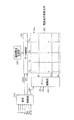
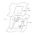
図1は、本発明の一実施例による液晶表示装置のブロック図である。図2は、本発明の一実施例による液晶表示装置の一つの画素に対する等価回路図である。
図1に示したように、本発明の一実施例による液晶表示装置は、液晶表示板組立体300と、これに連結されたゲート駆動部400及びデータ駆動部500と、データ駆動部500に連結された階調電圧生成部800と、これらを制御する信号制御部600と、を含む。
FIG. 1 is a block diagram of a liquid crystal display device according to an embodiment of the present invention. FIG. 2 is an equivalent circuit diagram for one pixel of a liquid crystal display device according to an embodiment of the present invention.
As shown in FIG. 1, the liquid crystal display according to an embodiment of the present invention includes a liquid crystal panel assembly 300, a
液晶表示板組立体300は、等価回路で見ると、複数の表示信号線(G1−Gn、D1−Dm)と、これに連結されていて、ほぼ行列状に配列されている複数の画素と、を含む。
表示信号線(G1−Gn、D1−Dm)は、ゲート信号(“走査信号”ともいう)を伝達する複数のゲート線(G1−Gn)と、データ信号を伝達するデータ線(D1−Dm)と、を含む。ゲート線(G1−Gn)は、ほぼ行方向に延長され互いにほぼ平行であり、データ線(D1−Dm)は、ほぼ列方向に延長され互いにほぼ平行である。
When viewed in an equivalent circuit, the liquid crystal display panel assembly 300 includes a plurality of display signal lines (G 1 -G n , D 1 -D m ) and a plurality of display signal lines connected to the display signal lines (G 1 -G n , D 1 -D m ). Pixels.
The display signal lines (G 1 -G n , D 1 -D m ) are a plurality of gate lines (G 1 -G n ) that transmit gate signals (also referred to as “scanning signals”) and data that transmit data signals. A line (D 1 -D m ). The gate lines (G 1 -G n ) extend in the row direction and are substantially parallel to each other, and the data lines (D 1 -D m ) extend in the column direction and are substantially parallel to each other.
各画素は、表示信号線(G1−Gn、D1−Dm)に連結された主スイッチング素子(Q1:第1スイッチング素子に相当)及び副スイッチング素子(Q2:第2スイッチング素子に相当)と、これに連結された液晶キャパシタ(CLC)及びストレージキャパシタ(CST)と、を含む。ストレージキャパシタ(CST)は必要に応じて省略することができる。 Each pixel has a main switching element (Q1: equivalent to the first switching element) and a sub-switching element (Q2: equivalent to the second switching element) connected to the display signal lines (G 1 -G n , D 1 -D m ). ), And a liquid crystal capacitor (C LC ) and a storage capacitor (C ST ) connected thereto. The storage capacitor (C ST ) can be omitted if necessary.
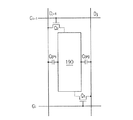
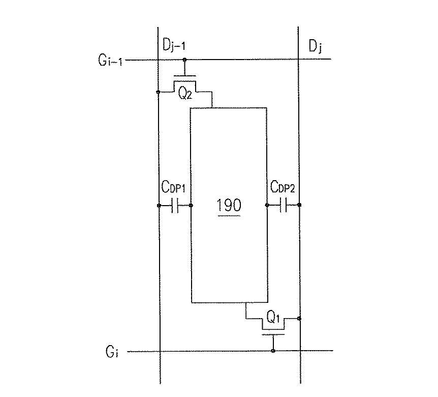
図2を参照すると、主スイッチング素子及び副スイッチング素子(Q1、Q2)は、下部表示板100に備えられており、互いに異なるゲート線(Gi-1、Gi)及び互いに異なるデータ線(Dj-1、Dj)に連結されている。主スイッチング素子及び副スイッチング素子(Q1、Q2)は、3端子素子であって、制御端子、入力端子、及び出力端子を備えている。例えば、i番目の画素行のj番目[以下、(i、j)と表す]の画素に接続されている主スイッチング素子(Q1)は、制御端子はi番目のゲート線(Gi)に連結されており、その入力端子はj番目のデータ線(Dj)に連結されており、出力端子は液晶キャパシタ(CLC)及びストレージキャパシタ(CST)に連結されている。また、(i、j)の画素の副スイッチング素子(Q2)は、制御端子は(i−1)番目のゲート線(Gi-1)に連結されており、その入力端子は(j−1)番目のデータ線(Dj-1)に連結されており、出力端子は液晶キャパシタ(CLC)及びストレージキャパシタ(CST)に連結されている。
Referring to FIG. 2, the main switching element and the sub switching element (Q1, Q2) are provided in the
液晶キャパシタ(CLC)は、下部表示板100の画素電極190及び上部表示板200の共通電極270を二端子として、二つの電極190、270の間の液晶層3は誘電体として機能する。画素電極190は二つのスイッチング素子(Q1、Q2)に連結されている。共通電極270は上部表示板200の全面に形成されていて、共通電圧(Vcom)の印加を受ける。図2とは異なって、共通電極270が下部表示板100に形成される場合もあり、この時には、二つの電極190、270が全て線状または棒状に形成される。
In the liquid crystal capacitor (C LC ), the
液晶キャパシタ(CLC)の補助的役割をするストレージキャパシタ(CST)は、下部表示板100に形成された別個の信号線(図示せず)が絶縁体を隔てて画素電極190と重畳して構成され、この別個の信号線には共通電圧(Vcom)などの決められた電圧が印加される。しかし、ストレージキャパシタ(CST)は、画素電極190が絶縁体を隔てて真上の前段ゲート線と重畳して構成されることもできる。
The storage capacitor (C ST ) serving as an auxiliary function of the liquid crystal capacitor (C LC ) has a separate signal line (not shown) formed on the
このように、画素電極190は、主スイッチング素子及び副スイッチング素子(Q1、Q2)を通じてゲート線(Gi-1、Gi)及びデータ線(Dj-1、Dj)に連結されており、図4に示したように、画素電極190と隣接する二つのデータ線(Dj-1、Dj)との間には寄生キャパシタ(CDP1、CDP2)が各々形成される。寄生キャパシタ(CDP1、CDP2)の静電容量が同一で、かつ主スイッチング素子(Q1)を通じて流れるリーク電流及び副スイッチング素子(Q2)を通じて流れるリーク電流が実質的に同一になるように、主スイッチング素子及び副スイッチング素子(Q1、Q2)を設計するのが好ましい。例えば、主スイッチング素子(Q1)及び副スイッチング素子(Q2)の構造及び大きさを互いに同一にし、画素電極190の中心点に対して二つのスイッチング素子(Q1、Q2)が180゜回転対称をなすように配置する。データ線(Dj-1、Dj)と画素電極190との間の距離も互いに同一である。
In this manner, the
平面的な配列で見ると、隣接する二つのゲート線(G1−Gn)及び隣接する二つのデータ線(D1−Dm)で区画される一つの領域に一つの画素が割当てられていて、各画素には主スイッチング素子及び副スイッチング素子(Q1、Q2)が配置されている。主スイッチング素子(Q1)は下側ゲート線に連結されており、副スイッチング素子(Q2)は上側ゲート線に連結されている。そして、主スイッチング素子及び副スイッチング素子(Q1、Q2)は互いに異なるデータ線に連結されている。また、一対のゲート線及びデータ線には互いに異なる画素の主スイッチング素子(Q1)及び副スイッチング素子(Q2)が連結されている。
<液晶表示装置の画素のスイッチング素子>
次に、図3及び図5乃至図6Bを参照して、本発明の実施例に係る液晶表示装置の、画素の主スイッチング素子及び副スイッチング素子の配置について、より詳細に説明する。
When viewed in a planar arrangement, one pixel is assigned to one area defined by two adjacent gate lines (G 1 -G n ) and two adjacent data lines (D 1 -D m ). Each pixel is provided with a main switching element and sub-switching elements (Q1, Q2). The main switching element (Q1) is connected to the lower gate line, and the sub switching element (Q2) is connected to the upper gate line. The main switching element and the sub switching elements (Q1, Q2) are connected to different data lines. Further, a main switching element (Q1) and a sub-switching element (Q2) of different pixels are connected to the pair of gate lines and data lines.
<Switching element of pixel of liquid crystal display device>
Next, with reference to FIGS. 3 and 5 to 6B, the arrangement of the main switching elements and the sub-switching elements of the pixel in the liquid crystal display device according to the embodiment of the present invention will be described in more detail.
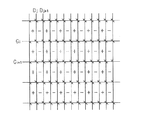
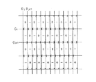
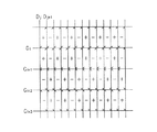
図3及び図5乃至図6Bは、本発明の実施例による液晶表示装置の画素のスイッチング素子の配置を示している。即ち、×印で示した主スイッチング素子及び副スイッチング素子と、ゲート線(G1−Gn)及びデータ線(D1−Dm)との連結関係を示している。下側ゲート線に連結されている×印は主スイッチング素子(Q1)を示しており、上側ゲート線に連結されている×印は副スイッチング素子(Q2)を示している。 3 and 5 to 6B show the arrangement of the switching elements of the pixels of the liquid crystal display device according to the embodiment of the present invention. In other words, the connection relationship between the main switching element and the sub switching element indicated by x, the gate line (G 1 -G n ), and the data line (D 1 -D m ) is shown. A cross mark connected to the lower gate line indicates a main switching element (Q1), and a cross mark connected to the upper gate line indicates a sub switching element (Q2).
図3及び図5乃至図6Bに示した配置で、各画素の主スイッチング素子(Q1)は下側ゲート線に連結されており、副スイッチング素子(Q2)は上側ゲート線に連結されている。各画素行の画素の主スイッチング素子及び副スイッチング素子(Q1、Q2)は互いに異なる方向のデータ線に連結されている。 In the arrangement shown in FIGS. 3 and 5 to 6B, the main switching element (Q1) of each pixel is connected to the lower gate line, and the sub-switching element (Q2) is connected to the upper gate line. The main switching elements and the sub-switching elements (Q1, Q2) of the pixels in each pixel row are connected to data lines in different directions.
また、図5に示した配置では、主スイッチング素子(Q1)及び副スイッチング素子(Q2)の位置は毎画素行ごとに変わる。つまり、隣接する画素行では、主スイッチング素子(Q1)は互いに異なる方向のデータ線に交互に連結されており、副スイッチング素子(Q2)も互いに異なる方向のデータ線に交互に連結されている。 Further, in the arrangement shown in FIG. 5, the positions of the main switching element (Q1) and the sub-switching element (Q2) change for each pixel row. That is, in adjacent pixel rows, the main switching elements (Q1) are alternately connected to data lines in different directions, and the sub-switching elements (Q2) are also alternately connected to data lines in different directions.
図5に示した四つの画素行の中では、最も上の画素行及び第3画素行の主スイッチング素子(Q1)は左側データ線に連結されており、副スイッチング素子(Q2)は右側データ線に連結されている。反対に、第2画素行及び第4画素行の主スイッチング素子(Q1)は右側データ線に、副スイッチング素子(Q2)は左側データ線に連結されている。 In the four pixel rows shown in FIG. 5, the main switching element (Q1) of the uppermost pixel row and the third pixel row is connected to the left data line, and the sub switching element (Q2) is the right data line. It is connected to. Conversely, the main switching elements (Q1) of the second pixel row and the fourth pixel row are connected to the right data line, and the sub switching elements (Q2) are connected to the left data line.
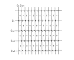
図6A及び図6Bに示した配置では、主スイッチング素子(Q1)及び副スイッチング素子(Q2)の位置は、二つの画素行ごとに変わる。言い換えれば、連続する二つの画素行(以下、“画素行群”とする)内の主スイッチング素子(Q1)は全て同一な方向のデータ線に連結されており、副スイッチング素子(Q2)も全て同一な方向のデータ線に連結されている。そして、隣接する画素行群の主スイッチング素子及び副スイッチング素子(Q1、Q2)は、互いに異なる方向のデータ線に連結されている。但し、液晶表示板組立体300の最も上、または最も下に位置した画素行は、それ自体が一つの画素行群になることができる。 In the arrangement shown in FIGS. 6A and 6B, the positions of the main switching element (Q1) and the sub-switching element (Q2) change every two pixel rows. In other words, the main switching elements (Q1) in two consecutive pixel rows (hereinafter referred to as “pixel row group”) are all connected to the data lines in the same direction, and all the sub-switching elements (Q2) are also connected. They are connected to data lines in the same direction. The main switching elements and sub-switching elements (Q1, Q2) in adjacent pixel row groups are connected to data lines in different directions. However, the uppermost or lowermost pixel row of the liquid crystal panel assembly 300 may be a single pixel row group.
図6Aに示した四つの画素行では、第1画素行群、つまり上側の二つの画素行の主スイッチング素子(Q1)は全て左側データ線に連結されており、副スイッチング素子(Q2)は全て右側データ線に連結されている。反対に、第2画素行群、つまり下側の二つの画素行の主スイッチング素子(Q1)は右側データ線に連結されており、副スイッチング素子(Q2)は左側データ線に連結されている。 In the four pixel rows shown in FIG. 6A, the first pixel row group, that is, the main switching elements (Q1) of the upper two pixel rows are all connected to the left data line, and the sub-switching elements (Q2) are all connected. Connected to the right data line. Conversely, the main switching elements (Q1) of the second pixel row group, that is, the lower two pixel rows, are connected to the right data line, and the sub-switching elements (Q2) are connected to the left data line.
図6Bに位置した四つの画素行では、第1画素行群、つまり最も上の画素行の主スイッチング素子(Q1)は左側データ線に、副スイッチング素子(Q2)は右側データ線に連結されている。第2画素行群、つまり第2、第3画素行の主スイッチング素子(Q1)は右側データ線に、副スイッチング素子(Q2)は左側データ線に連結されている。そして、最後の行群、つまり、最も下の画素行の主スイッチング素子(Q1)は左側データ線に、副スイッチング素子(Q2)は右側データ線に連結されている。 In the four pixel rows located in FIG. 6B, the first pixel row group, that is, the main switching element (Q1) of the uppermost pixel row is connected to the left data line, and the sub-switching element (Q2) is connected to the right data line. Yes. The main switching elements (Q1) of the second pixel row group, that is, the second and third pixel rows, are connected to the right data line, and the sub switching elements (Q2) are connected to the left data line. The main switching element (Q1) in the last row group, that is, the lowermost pixel row is connected to the left data line, and the sub switching element (Q2) is connected to the right data line.
図5乃至図6Bに示した主及び副スイッチング素子(Q1、Q2)の配置を整理すると、少なくとも一つの画素行を含む各画素行群内の主スイッチング素子(Q1)は全て同じ方向のデータ線に連結されており、副スイッチング素子(Q2)も全て同じ方向のデータ線に連結されている。そして、隣接する二つの画素行群の主スイッチング素子(Q1)は互いに異なる方向のデータ線に連結されており、副スイッチング素子(Q2)も互いに異なる方向のデータ線に連結されている。 If the arrangement of the main and sub switching elements (Q1, Q2) shown in FIGS. 5 to 6B is arranged, the main switching elements (Q1) in each pixel row group including at least one pixel row are all data lines in the same direction. The sub switching elements (Q2) are all connected to the data lines in the same direction. The main switching elements (Q1) of two adjacent pixel row groups are connected to data lines in different directions, and the sub-switching elements (Q2) are also connected to data lines in different directions.
一方、色表示を実現するためには、各画素が三原色のうちの一つを固有に表示したり(空間分割)、各画素が時間によって交互に三原色を表示するように(時間分割)して、これら三原色の空間的、時間的合計で所望の色相が認識されるようにする。図2には空間分割の一例として、上部表示板200には、各画素の画素電極190に対応する領域に赤色、緑色、または青色のカラーフィルター230が形成されている。尚、図2ではカラーフィルター230は上部表示板200に形成されているが、これとは異なり、カラーフィルター230は、下部表示板100の画素電極190上または下に形成されることもできる。
On the other hand, in order to realize color display, each pixel displays one of the three primary colors uniquely (space division), or each pixel displays the three primary colors alternately according to time (time division). The desired hue is recognized by the spatial and temporal sum of these three primary colors. As an example of space division in FIG. 2, a red, green, or
図3及び図5乃至図6Bでは、カラーフィルター230が行方向には赤色、緑色、青色の順に配列されていて、各画素列は一つの色相のカラーフィルター230のみを含む、ストライプ配列をなしている。
3 and 5 to 6B, the
液晶表示板組立体300の二つの表示板100、200のうちの少なくとも一つの外側面には、光を偏光させる偏光子(図示せず)が付着されている。
階調電圧生成部800は、画素の透過率に関する二組の複数の階調電圧を生成する。二組うちの一組は共通電圧(Vcom)に対して正の値を有し、他の一組は負の値を有する。
A polarizer (not shown) that polarizes light is attached to at least one outer surface of the two
The
ゲート駆動部400は、液晶表示板組立体300のゲート線(G1−Gn)に連結されていて、外部からのゲートオン電圧(Von)及びゲートオフ電圧(Voff)の組み合わせからなるゲート信号をゲート線(G1−Gn)に印加する。そして、ゲート駆動部400は、複数の集積回路を含む。
The
データ駆動部500は、液晶表示板組立体300のデータ線(D1−Dm)に連結されていて、階調電圧生成部800からの階調電圧を選択してデータ信号として画素に印加する。データ駆動部50は、複数の集積回路を含む。
The
複数のゲート駆動集積回路またはデータ駆動集積回路は、TCP(tape carrier package)(図示せず)に実装されてTCPが液晶表示板組立体300に付着されることもできる。また、これらの集積回路は、TCPを使用せずにガラス基板上に直接付着されることもでき(chip on glass:COG実装方式)、これらの集積回路と同様の機能を行う回路が画素の薄膜トランジスタと共に液晶表示板組立体300に直接形成されることもできる。 A plurality of gate driving integrated circuits or data driving integrated circuits may be mounted on a TCP (tape carrier package) (not shown), and the TCP may be attached to the liquid crystal panel assembly 300. In addition, these integrated circuits can be directly attached on a glass substrate without using TCP (chip on glass: COG mounting method), and a circuit that performs the same function as these integrated circuits is a thin film transistor in a pixel. In addition, the liquid crystal panel assembly 300 may be directly formed.
信号制御部600は、ゲート駆動部400及びデータ駆動部500などの動作を制御する制御信号を生成し、各々該当する制御信号をゲート駆動部400及びデータ駆動部500に提供する。
<液晶表示装置の表示動作>
次に、このような液晶表示装置の表示動作について、詳細に説明する。
The
<Display operation of liquid crystal display device>
Next, the display operation of such a liquid crystal display device will be described in detail.
信号制御部600は、外部のグラフィック制御機(図示せず)からRGB映像信号(R、G、B)及びその表示を制御する入力制御信号を提供される。ここで、入力制御信号とは、例えば垂直同期信号(Vsync)、水平同期信号(Hsync)、メインクロック(MCLK)及びデータイネーブル信号(DE)などである。信号制御部600は、入力映像信号(R、G、B)及び入力制御信号に基づいて映像信号(R、G、B)を液晶表示板組立体300の動作条件に合うように適切に処理し、ゲート制御信号(CONT1)及びデータ制御信号(CONT2)などを生成する。そして、ゲート制御信号(CONT1)をゲート駆動部400に出力し、データ制御信号(CONT2)及び処理した映像信号(DAT)をデータ駆動部500に出力する。
The
ゲート制御信号(CONT1)は、ゲートオン電圧(Von)の出力開始を指示する垂直同期開始信号(STV)、ゲートオン電圧(Von)の出力時期を制御するゲートクロック信号(CPV)、及びゲートオン電圧(Von)の持続時間を限定する出力イネーブル信号(OE)などを含む。 The gate control signal (CONT1) includes a gate clock signal for controlling the output time of the vertical synchronization start signal for instructing the output start of the gate-on voltage (V on) (STV), a gate-on voltage (V on) (CPV), and the gate-on voltage An output enable signal (OE) for limiting the duration of (V on ) is included.
データ制御信号(CONT2)は、映像データ(DAT)の入力開始を知らせる水平同期開始信号(STH)、データ線(D1−Dm)に当該データ電圧の印加を指示するロード信号(LOAD)、共通電圧(Vcom)に対するデータ電圧の極性(以下、“共通電圧に対するデータ電圧の極性”を略して“データ電圧の極性”とする)を反転させる反転信号(RVS)、及びデータクロック信号(HCLK)などを含む。 The data control signal (CONT2) includes a horizontal synchronization start signal (STH) for informing the start of input of video data (DAT), a load signal (LOAD) for instructing the data lines (D 1 -D m ) to apply the data voltage, An inversion signal (RVS) for inverting the polarity of the data voltage with respect to the common voltage (V com ) (hereinafter, “the polarity of the data voltage with respect to the common voltage” is abbreviated to “the polarity of the data voltage”), and the data clock signal (HCLK ) Etc.
データ駆動部500は、信号制御部600からのデータ制御信号(CONT2)によって一つの画素行の画素に対応する映像データ(DAT)を順に受けてシフトさせ、階調電圧生成部800からの階調電圧のうちの各映像データ(DAT)に対応する階調電圧を選択することによって、映像データ(DAT)を当該データ電圧に変換して、当該データ線(D1−Dm)に印加する。
The
ゲート駆動部400は、信号制御部600からのゲート制御信号(CONT1)によってゲートオン電圧(Von)をゲート線(G1−Gn)に印加する。前述したように、一つのゲート線には二つの画素行のスイッチング素子(Q1、Q2)が連結されている。つまり、ゲート線は、当該画素行の画素の主スイッチング素子(Q1)及び次の画素行の画素の副スイッチング素子(Q2)に連結されている。そのため、ゲート線にゲートオン電圧(VON)を印加すると、ゲートオン電圧(Von)は当該画素行の画素の主スイッチング素子(Q1)及び次の画素行の画素の副スイッチング素子(Q2)を同時にオンさせる。これによってデータ線(D1−DM)に印加されたデータ電圧は画素に伝達される。
The
二つの画素行の画素に印加されたデータ電圧と共通電圧(Vcom)との差は、液晶キャパシタ(CLC)の充電電圧、つまり画素電圧として現れる。各画素の液晶分子は、画素電圧の大きさによってその配向が異なり、それによって液晶層3を通過する光の偏光が変化する。このような偏光の変化は表示板100、200に付着された偏光子(図示せず)によって光の透過率の変化として現れる。
The difference between the data voltage applied to the pixels in the two pixel rows and the common voltage (V com ) appears as the charging voltage of the liquid crystal capacitor (C LC ), that is, the pixel voltage. The orientation of the liquid crystal molecules of each pixel varies depending on the magnitude of the pixel voltage, and the polarization of light passing through the
副スイッチング素子(Q2)を通じて直前の画素行の画素に該当するデータ電圧の印加を受けた画素行は、1水平周期(または“1H”)[水平同期信号(Hsync)、データイネーブル信号(DE)、ゲートクロック(CPV)の一周期]後に、主スイッチング素子(Q1)を通じて当該画素行の画素に該当するデータ電圧の印加を受ける。 A pixel row that has received the application of the data voltage corresponding to the pixel in the previous pixel row through the sub-switching element (Q2) is 1 horizontal cycle (or “1H”) [horizontal synchronization signal (H sync ), data enable signal (DE ), After one cycle of the gate clock (CPV), the data voltage corresponding to the pixel in the pixel row is applied through the main switching element (Q1).
データ駆動部500及びゲート駆動部400は、1水平周期で次の画素行の画素に対して同一な動作を繰り返す。このような方式で、1フレームの間に全てのゲート線(G1−Gn)に対して順にゲートオン電圧(Von)を印加し、全ての画素にデータ電圧を印加する。1フレームが終わると次のフレームが始まり、各画素に印加されるデータ電圧の極性が直前のフレームでの極性と反対になるように、データ駆動部500に印加される反転信号(RVS)の状態が制御される(“フレーム反転”)。
The
このようなフレーム反転以外にも、データ駆動部500は、1フレーム内で隣接するデータ線(D1−Dm)を通じて流れるデータ電圧の極性を反転させ、それによってデータ電圧の印加を受けた画素電圧の極性も変化する。ところが、図3及び図5乃至図6Bに示したように、画素及びデータ線(D1−Dm)の連結が多様なので、データ駆動部500での極性反転パターン及び液晶表示板組立体300の画面に現れる画素電圧の極性反転パターンが異なって現れる。以下、データ駆動部500での反転を“駆動部反転”といい、画面に現れる反転を“見かけ反転”という。
<反転形態>
次に、本発明の実施例による反転形態について、図3乃至図6Bを参照して詳細に説明する。
In addition to such frame inversion, the
<Inverted form>
Next, the inversion according to the embodiment of the present invention will be described in detail with reference to FIGS. 3 to 6B.
図3及び図5乃至図6Bで、駆動部反転は列反転であって、一つのデータ線に流れるデータ電圧は常に同一な極性であり、隣接する二つのデータ線に流れるデータ電圧は反対の極性である。 3 and 5 to 6B, the driving unit inversion is column inversion, and the data voltage flowing through one data line always has the same polarity, and the data voltages flowing through two adjacent data lines have opposite polarities. It is.
図3は見かけ反転が列反転である場合を示している。
図3で、i番目のゲート線(Gi)にゲートオン電圧(Von)が印加されると、ゲート線(Gi)に連結されたi番目の画素行(図3の第1画素行)に配置されている主スイッチング素子(Q1)と(i+1)番目の画素行(図3の第2画素行)に配置されている副スイッチング素子(Q2)とが同時にオンする。そして、データ線(D1−Dm)と主スイッチング素子及び副スイッチング素子(Q1、Q2)とを通じて画素にデータ電圧が印加される。この時、駆動部反転は“列反転”であるので、互いに隣接するデータ線には反対の極性のデータ電圧が印加される。本発明の実施例で、j番目のデータ線(Dj)に“+”の極性のデータ電圧が印加されると仮定すると、図3の第1画素行(i番目の画素行)で主スイッチング素子(Q1)を通じて各当該画素に印加されるデータ電圧の極性は、図3に示した通りである。また、副スイッチング素子(Q2)を通じて第2画素行[(i+1)番目の画素行]にも第1画素行のデータ電圧が印加される。
FIG. 3 shows a case where the apparent inversion is a column inversion.
In Figure 3, i-th gate line when (G i) to the gate-on voltage (V on) is applied, is connected to a gate line (G i) i th pixel row (first pixel row in FIG. 3) The main switching element (Q1) arranged in the (1) and the sub-switching element (Q2) arranged in the (i + 1) th pixel row (second pixel row in FIG. 3) are simultaneously turned on. Then, a data voltage is applied to the pixel through the data line (D 1 -D m ) and the main switching element and the sub switching element (Q1, Q2). At this time, since the drive unit inversion is “column inversion”, data voltages having opposite polarities are applied to the data lines adjacent to each other. In the embodiment of the present invention, assuming that a data voltage having a polarity of “+” is applied to the j-th data line (D j ), main switching is performed in the first pixel row (i-th pixel row) of FIG. The polarity of the data voltage applied to each pixel through the element (Q1) is as shown in FIG. The data voltage of the first pixel row is also applied to the second pixel row [(i + 1) th pixel row] through the sub-switching element (Q2).
次に、(i+1)番目のゲート線(Gi+1)にゲートオン電圧(Von)が印加されると、このゲート線(Gi+1)に連結された主スイッチング素子及び副スイッチング素子(Q1、Q2)が全てオンする。導通した主スイッチング素子及び副スイッチング素子(Q1、Q2)を通じて各々連結されたデータ線(D1−Dm)に(i+1)番目の画素行のデータ電圧が伝達される。これによって、i番目のゲート線(Gi)に連結された(i+1)番目の画素行の副スイッチング素子(Q2)によってi番目の画素行のデータ電圧が既に充電されていた(i+1)番目の画素行の各画素は、(i+1)番目の画素行のデータ電圧で再充電される。 Next, when a gate-on voltage (V on ) is applied to the (i + 1) -th gate line (G i + 1 ), the main switching element and sub-switching connected to the gate line (G i + 1 ) All the elements (Q1, Q2) are turned on. The data voltage of the (i + 1) th pixel row is transmitted to the connected data lines (D 1 -D m ) through the conductive main switching elements and sub switching elements (Q1, Q2). Accordingly, the data voltage of the i-th pixel row is already charged by the sub-switching element (Q2) of the (i + 1) -th pixel row connected to the i-th gate line (G i ). Each pixel in the pixel row is recharged with the data voltage of the (i + 1) th pixel row.
このような動作が各画素行ごとに繰り返されて、図3のように画素が配置されると、見かけ反転は列反転になる。
このように、一つの画素に対角線で対向するように二つのスイッチング素子(Q1、Q2)を配置した構造の液晶表示装置は、垂直クロストークの影響を大幅に減少させることができる。以下よりこれについて詳述する。
(垂直クロストーク)
一般に、垂直クロストークは、画素電極と隣接するデータ線との間に発生する寄生容量や画素のスイッチング素子をオフした後に発生するリーク電流の影響により、画素電極の電圧が変化することに起因して発生するといわれている。
When such an operation is repeated for each pixel row and pixels are arranged as shown in FIG. 3, the apparent inversion becomes a column inversion.
As described above, the liquid crystal display device having the structure in which the two switching elements (Q1, Q2) are disposed so as to face one pixel diagonally can greatly reduce the influence of vertical crosstalk. This will be described in detail below.
(Vertical crosstalk)
In general, vertical crosstalk is caused by a change in the voltage of the pixel electrode due to a parasitic capacitance generated between the pixel electrode and an adjacent data line or a leakage current generated after the pixel switching element is turned off. It is said that it occurs.
図4を参照して、画素電極とデータ線との間の寄生容量による画素電極の電圧変化量をより具体的に説明する。
前述したように、画素電極190は、主スイッチング素子及び副スイッチング素子(Q1、Q2)を通じてゲート線(Gi-1、Gj)及びデータ線(Dj-1、Dj)に連結されている。画素電極190と隣接する二つのデータ線(Dj-1、Dj)との間には寄生キャパシタ(CDP1、CDP2)が各々形成される。ここで、キャパシタ及びそのキャパシタの静電容量は同一な図面符号で示す。
With reference to FIG. 4, the voltage change amount of the pixel electrode due to the parasitic capacitance between the pixel electrode and the data line will be described more specifically.
As described above, the
画素電極190とデータ線(Dj-1、Dj)との間の寄生容量(CDP1、CDP2)による画素電極190の電圧変化量(△V)は、下記の式で示される。
The voltage change amount (ΔV) of the
列反転を考慮して、隣接する二つのデータ線(Dj-1、Dj)に流れるデータ電圧が同一な階調を示すとすれば、(V2−Vcom)=−(V1−Vcom)であり、(V2´−Vcom)=−(V1´−Vcom)である。即ち、(V2−V2´)=−(V1−V1´)である。したがって、(1)式は下記の(2)式のように簡略化することができる。 Considering column inversion, if the data voltages flowing in two adjacent data lines (D j−1 , D j ) indicate the same gradation, (V 2 −V com ) = − (V 1 − a V com), (V 2 ' -V com) = - (V 1' is a-V com). That is, (V 2 −V 2 ′) = − (V 1 −V 1 ′). Therefore, equation (1) can be simplified as equation (2) below.
一方、漏洩電流による画素電極190の電圧変化量(△V)は、下記の式で示される。
On the other hand, the voltage change amount (ΔV) of the
図4に示したように、本発明の実施例では、一つの画素に同一な構造のスイッチング素子(Q1、Q2)が対角線で対向するように配置されるので、画素電極190がその中心点に対して180゜回転対称をなすように形成することができ、隣接する二つのデータ線(Dj-1、Dj)から見た画素電極190の幾何学的構造は同一である。したがって、画素電極190とそれに隣接する二つのデータ線(Dj-1、Dj)との間に形成された寄生容量(CDP1、CDP2)は同一であり、二つの寄生容量(CDP1、CDP2)の間の容量差による電圧変化はほとんど発生しない。
As shown in FIG. 4, in the embodiment of the present invention, since the switching elements (Q1, Q2) having the same structure are arranged diagonally opposite to one pixel, the
また、主スイッチング素子及び副スイッチング素子(Q1、Q2)は、反対の極性のデータ電圧が印加されるデータ線にそれぞれ連結されているので、副スイッチング素子(Q2)を通じてリーク電流(Ioff2)が流れて、スイッチング素子(Q1)を通じてリーク電流(Ioff1)が流れる。反対に、主スイッチング素子(Q1)を通じてリーク電流(Ioff1)が流れて、副スイッチング素子(Q2)を通じてリーク電流(Ioff2)が流れる。この時、主スイッチング素子及び副スイッチング素子(Q1、Q2)の構造が同一なので、二つのリーク電流(Ioff1、Ioff2)の大きさはほぼ同一で、Ioff1−Ioff2=0になる。即ち、リーク電流は互いに相殺される。したがって、画素電極190の電圧変化量(△V)が大幅に減少し、これによって垂直クロストークの影響が大幅に減少する。
Further, since the main switching element and the sub switching element (Q1, Q2) are respectively connected to the data lines to which the data voltages having opposite polarities are applied, the leakage current (I off2 ) is passed through the sub switching element (Q2). A leakage current (I off1 ) flows through the switching element (Q1). Conversely, Lord leakage current through the switching element (Q1) (I off1) flows, the leakage current (I off2) flows through the auxiliary switching element (Q2). At this time, since the structure is the same of the main switching element and the sub-switching element (Q1, Q2), the size of the two leakage current (I off1, I off2) is substantially the same, the I off1 -I off2 = 0. That is, the leakage currents cancel each other. Therefore, the amount of voltage change (ΔV) of the
図5の場合には、主スイッチング素子及び副スイッチング素子(Q1、Q2)の位置が毎画素行ごとに変わるので、見かけ反転が1×1ドット反転になる。一方、図6A及び図6Bの場合には、主スイッチング素子及び副スイッチング素子(Q1、Q2)の位置が二つの画素行ごとに変わるので、見かけ反転が2×1ドット反転になる。 In the case of FIG. 5, since the positions of the main switching element and the sub switching elements (Q1, Q2) change for every pixel row, the apparent inversion becomes 1 × 1 dot inversion. On the other hand, in the case of FIGS. 6A and 6B, the positions of the main switching element and the sub-switching elements (Q1, Q2) are changed every two pixel rows, so that the apparent inversion is 2 × 1 dot inversion.
このように見かけ反転がドット反転になれば、前述したように、一つの画素に二つのスイッチング素子(Q1、Q2)を配置して垂直クロストークの影響を減少させることができることに加えて、画素電圧が正極性である場合及び負極性である場合にキックバック電圧によって現れる輝度の差が分散されて現れるので、縦行の不良が減少する。また、主スイッチング素子(Q1)の位置が画素行群単位で変わるので、画像の境界部分を除いて、1フレームのうちの1/2フレームの間に隣接するデータ線の間には極性は反対だがほぼ同一な値を有するデータ電圧が印加される確率が非常に高い。そのため、画素電極190の電圧変化量(△V)を著しく減少させて、垂直クロストークの影響をさらに大幅に減少させることができる。
If the apparent inversion becomes dot inversion in this way, as described above, two switching elements (Q1, Q2) can be arranged in one pixel to reduce the influence of vertical crosstalk. When the voltage is positive and negative, the difference in luminance that appears due to the kickback voltage appears in a distributed manner, thereby reducing longitudinal defects. Further, since the position of the main switching element (Q1) changes in units of pixel row groups, the polarity is opposite between adjacent data lines during 1/2 frame of one frame except for the boundary portion of the image. However, the probability that a data voltage having substantially the same value is applied is very high. Therefore, the voltage change amount (ΔV) of the
一方、追加された副スイッチング素子(Q2)は修理用に利用することができる。図2を再び参考にすれば、画素にデータ電圧を伝達する主スイッチング素子(Q1)が短絡した場合には、レーザー切断などで主スイッチング素子(Q1)と連結されたデータ線から画素電極190を分離する。このようにすれば、画素電極190には副スイッチング素子(Q2)を通じて隣接する画素のデータ電圧が充電される。この場合、充電された電圧がたとえ所望のデータ電圧でないとしても、隣接する画素のデータ電圧であるので、画面にはそれほど大きな影響がない。また、主スイッチング素子(Q1)が断線した場合にも、前記のように当該画素電極190に副スイッチング素子(Q2)を通じて隣接する画素のデータ電圧が充電されるので、自然に修理が行われる。
On the other hand, the added sub switching element (Q2) can be used for repair. Referring to FIG. 2 again, when the main switching element (Q1) for transmitting the data voltage to the pixel is short-circuited, the
また、副スイッチング素子(Q2)は当該画素に所望のデータ電圧を充電するのには実質的に影響を与えないので、副スイッチング素子(Q2)が短絡した場合には、レーザー切断などで副スイッチング素子(Q2)と連結されたデータ線から画素電極190を分離するが、断線した場合には、特別な措置を行なわなくてもよい。
In addition, since the sub switching element (Q2) does not substantially affect the charging of the desired data voltage to the pixel, when the sub switching element (Q2) is short-circuited, the sub switching element (Q2) is switched by laser cutting or the like. The
以上で、本発明の好ましい実施例について詳細に説明したが、本発明の権利範囲はこれに限定されず、請求の範囲で定義している本発明の基本概念を利用した当業者による様々な変形及び改良形態も、本発明の権利範囲に属する。 The preferred embodiments of the present invention have been described in detail above, but the scope of the present invention is not limited thereto, and various modifications by those skilled in the art using the basic concept of the present invention defined in the claims. And improvements are also within the scope of the present invention.
230 カラーフィルター
300 液晶表示板組立体
400 ゲート駆動部
500 データ駆動部
600 信号制御部
800 階調電圧生成部
Q1、Q2 主、副スイッチング素子
D1−Dm データ線
G1−Gn ゲート線
230 color filter 300 liquid crystal
Claims (17)
前記第1及び第2スイッチング素子に連結されており、前記第1及び第2スイッチング素子をオンさせるゲートオン電圧を伝達する複数のゲート線と、
前記第1及び第2スイッチング素子に連結されており、データ電圧を伝達する複数のデータ線と、を含み、
前記第1及び第2スイッチング素子は互いに異なる前記ゲート線及びデータ線に連結されており、
前記画素電極を介して隣接する二つの前記データ線との間には、静電容量が実質的に同一である第1キャパシタ及び第2寄生キャパシタが形成されていることを特徴とする、液晶表示装置。 At least one pixel row among a plurality of pixels arranged in a matrix and each including a first switching element, a second switching element, and a pixel electrode connected to the first and second switching elements A plurality of pixel row groups including:
A plurality of gate lines connected to the first and second switching elements and transmitting a gate-on voltage for turning on the first and second switching elements;
A plurality of data lines connected to the first and second switching elements and transmitting a data voltage;
The first and second switching elements are connected to the gate line and the data line different from each other,
A liquid crystal display, wherein a first capacitor and a second parasitic capacitor having substantially the same capacitance are formed between two data lines adjacent to each other through the pixel electrode. apparatus.
前記第1及び第2スイッチング素子に連結されており、前記第1及び第2スイッチング素子をオンさせるゲートオン電圧を伝達する複数のゲート線と、
前記第1及び第2スイッチング素子に連結されており、データ電圧を伝達する複数のデータ線と、を含み、
前記第1及び第2スイッチング素子は互いに異なるゲート線及びデータ線に連結されており、
前記第1スイッチング素子を通じて流れる第1リーク電流と前記第2スイッチング素子を通じて流れる第2リーク電流とが実質的に等しくなるように、前記第1及び第2スイッチング素子が配置されていることを特徴とする、液晶表示装置。 A plurality of pixel row groups each including at least one pixel row among a plurality of pixels arranged in a matrix and each including a first switching element and a second switching element;
A plurality of gate lines connected to the first and second switching elements and transmitting a gate-on voltage for turning on the first and second switching elements;
A plurality of data lines connected to the first and second switching elements and transmitting a data voltage;
The first and second switching elements are connected to different gate lines and data lines,
The first and second switching elements are arranged such that a first leakage current flowing through the first switching element and a second leakage current flowing through the second switching element are substantially equal. A liquid crystal display device.
前記第1及び第2スイッチング素子に連結されており、前記第1及び第2スイッチング素子をオンさせるゲートオン電圧を伝達する複数のゲート線と、
前記第1及び第2スイッチング素子に連結されており、データ電圧を伝達する複数のデータ線と、を含み、
前記第1及び第2スイッチング素子は互いに異なるゲート線及びデータ線に連結されており、
1つの前記データ線に流れる前記データ電圧の極性は一定であって、隣接する前記データ線に流れる前記データ電圧の極性は互いに反対であることを特徴とする、液晶表示装置。 A plurality of pixel row groups each including at least one pixel row among a plurality of pixels arranged in a matrix and each including a first switching element and a second switching element;
A plurality of gate lines connected to the first and second switching elements and transmitting a gate-on voltage for turning on the first and second switching elements;
A plurality of data lines connected to the first and second switching elements and transmitting a data voltage;
The first and second switching elements are connected to different gate lines and data lines,
The liquid crystal display device according to claim 1, wherein the polarity of the data voltage flowing through one data line is constant and the polarity of the data voltage flowing through the adjacent data line is opposite to each other.
Applications Claiming Priority (1)
| Application Number | Priority Date | Filing Date | Title |
|---|---|---|---|
| KR1020040022053A KR101018755B1 (en) | 2004-03-31 | 2004-03-31 | Liquid crystal display |
Publications (1)
| Publication Number | Publication Date |
|---|---|
| JP2005292831A true JP2005292831A (en) | 2005-10-20 |
Family
ID=35053722
Family Applications (1)
| Application Number | Title | Priority Date | Filing Date |
|---|---|---|---|
| JP2005098932A Pending JP2005292831A (en) | 2004-03-31 | 2005-03-30 | Liquid crystal display |
Country Status (5)
| Country | Link |
|---|---|
| US (1) | US20050219196A1 (en) |
| JP (1) | JP2005292831A (en) |
| KR (1) | KR101018755B1 (en) |
| CN (1) | CN100451786C (en) |
| TW (1) | TW200540760A (en) |
Cited By (1)
| Publication number | Priority date | Publication date | Assignee | Title |
|---|---|---|---|---|
| JP2014074798A (en) * | 2012-10-04 | 2014-04-24 | Japan Display Inc | Liquid crystal display device |
Families Citing this family (25)
| Publication number | Priority date | Publication date | Assignee | Title |
|---|---|---|---|---|
| JP2006189477A (en) * | 2004-12-28 | 2006-07-20 | Koninkl Philips Electronics Nv | Color liquid crystal display device |
| JP2007121767A (en) * | 2005-10-28 | 2007-05-17 | Nec Lcd Technologies Ltd | Liquid crystal display |
| CN101432793B (en) * | 2006-07-14 | 2012-02-01 | 夏普株式会社 | Active matrix substrate and display device with the same |
| CN101467098B (en) * | 2006-08-02 | 2011-08-24 | 夏普株式会社 | Active matrix substrate and display device having the same |
| WO2008029536A1 (en) * | 2006-09-06 | 2008-03-13 | Sharp Kabushiki Kaisha | Liuid crystal display device and its driving method |
| JP5132566B2 (en) * | 2006-09-28 | 2013-01-30 | シャープ株式会社 | Liquid crystal display device and television receiver |
| US8107032B2 (en) | 2006-11-02 | 2012-01-31 | Sharp Kabushiki Kaisha | Active matrix substrate and display device having the same |
| JP4450016B2 (en) * | 2007-06-12 | 2010-04-14 | ソニー株式会社 | Liquid crystal display device and liquid crystal driving circuit |
| TWI396156B (en) * | 2008-10-31 | 2013-05-11 | Au Optronics Corp | Data line driving method |
| TWI408474B (en) * | 2009-04-24 | 2013-09-11 | Innolux Corp | Subpixel structure and liquid crystal display panel |
| CN101963723B (en) * | 2009-07-22 | 2012-05-30 | 北京京东方光电科技有限公司 | TFT-LCD (Thin Film Transistor Liquid Crystal Display) array substrate and manufacturing method thereof |
| JP5728895B2 (en) * | 2010-11-09 | 2015-06-03 | セイコーエプソン株式会社 | Electro-optical device and electronic apparatus |
| US9165518B2 (en) | 2011-08-08 | 2015-10-20 | Samsung Display Co., Ltd. | Display device and driving method thereof |
| US9299301B2 (en) | 2011-11-04 | 2016-03-29 | Samsung Display Co., Ltd. | Display device and method for driving the display device |
| US9208736B2 (en) | 2011-11-28 | 2015-12-08 | Samsung Display Co., Ltd. | Display device and driving method thereof |
| US9129572B2 (en) * | 2012-02-21 | 2015-09-08 | Samsung Display Co., Ltd. | Display device and related method |
| CN104267551B (en) * | 2014-09-19 | 2017-06-09 | 京东方科技集团股份有限公司 | A kind of array base palte, display panel and display device |
| CN105182647B (en) * | 2015-10-16 | 2019-01-11 | 深圳市华星光电技术有限公司 | array substrate, liquid crystal display panel and driving method |
| CN105913791B (en) * | 2016-06-24 | 2019-09-24 | 厦门天马微电子有限公司 | Display device, array substrate and its driving method |
| KR102521356B1 (en) * | 2017-12-19 | 2023-04-13 | 삼성디스플레이 주식회사 | Display device |
| CN109164653A (en) * | 2018-09-20 | 2019-01-08 | 深圳市华星光电技术有限公司 | A kind of liquid crystal display panel and its driving method |
| KR102754225B1 (en) * | 2019-08-28 | 2025-01-13 | 삼성디스플레이 주식회사 | Display device and method thereof |
| CN111427201A (en) * | 2020-04-30 | 2020-07-17 | 京东方科技集团股份有限公司 | Array substrate and display panel |
| CN113409718B (en) * | 2021-05-27 | 2022-02-18 | 惠科股份有限公司 | Display panel and display device |
| CN115394262B (en) * | 2022-08-26 | 2023-11-24 | 惠科股份有限公司 | Pixel driving circuit and display panel |
Citations (3)
| Publication number | Priority date | Publication date | Assignee | Title |
|---|---|---|---|---|
| JPH04237092A (en) * | 1991-01-21 | 1992-08-25 | Matsushita Electric Ind Co Ltd | Liquid crystal display device and projection display device using the same |
| JPH06274130A (en) * | 1993-03-22 | 1994-09-30 | Matsushita Electric Ind Co Ltd | Liquid crystal display device and liquid crystal projection type television using the same |
| JP2002202736A (en) * | 2000-10-04 | 2002-07-19 | Matsushita Electric Ind Co Ltd | Display device and driving method thereof |
Family Cites Families (14)
| Publication number | Priority date | Publication date | Assignee | Title |
|---|---|---|---|---|
| DE3581498D1 (en) * | 1984-11-16 | 1991-02-28 | Matsushita Electric Industrial Co Ltd | ACTIVE MATRIX CIRCUIT FOR LIQUID CRYSTAL DISPLAYS. |
| JPH05273522A (en) * | 1992-01-08 | 1993-10-22 | Matsushita Electric Ind Co Ltd | Display device and display device using the same |
| JPH09127916A (en) * | 1995-10-31 | 1997-05-16 | Victor Co Of Japan Ltd | Liquid crystal display device |
| US6014191A (en) * | 1996-07-16 | 2000-01-11 | Samsung Electronics Co., Ltd. | Liquid crystal display having repair lines that cross data lines twice and cross gate lines in the active area and related repairing methods |
| KR100251091B1 (en) * | 1996-11-29 | 2000-04-15 | 구본준 | Manufacturing method of liquid crystal display device and liquid crystal display device manufactured by the manufacturing method |
| US5808706A (en) * | 1997-03-19 | 1998-09-15 | Samsung Electronics Co., Ltd. | Thin-film transistor liquid crystal display devices having cross-coupled storage capacitors |
| JP2001282201A (en) * | 2000-03-31 | 2001-10-12 | Internatl Business Mach Corp <Ibm> | Display device, liquid crystal display panel, liquid crystal display device and method for driving liquid crystal display device |
| KR100759974B1 (en) * | 2001-02-26 | 2007-09-18 | 삼성전자주식회사 | Liquid crystal display device and driving method thereof. |
| KR100848108B1 (en) * | 2001-03-16 | 2008-07-24 | 삼성전자주식회사 | liquid crystal display, thin film transistor array plate and method for fabricating the plate |
| KR100469342B1 (en) * | 2001-07-11 | 2005-02-02 | 엘지.필립스 엘시디 주식회사 | Liquid Crystal Display Device |
| US6862052B2 (en) * | 2001-12-14 | 2005-03-01 | Samsung Electronics Co., Ltd. | Liquid crystal display, thin film transistor array panel for liquid crystal display and manufacturing method thereof |
| KR100869738B1 (en) * | 2001-12-19 | 2008-11-21 | 엘지디스플레이 주식회사 | Liquid crystal display apparatus |
| DE10259326B4 (en) * | 2001-12-19 | 2018-11-29 | Lg Display Co., Ltd. | liquid-crystal display |
| KR20060025785A (en) * | 2004-09-17 | 2006-03-22 | 삼성전자주식회사 | Liquid crystal display |
-
2004
- 2004-03-31 KR KR1020040022053A patent/KR101018755B1/en not_active Expired - Fee Related
-
2005
- 2005-03-30 JP JP2005098932A patent/JP2005292831A/en active Pending
- 2005-03-30 US US11/093,096 patent/US20050219196A1/en not_active Abandoned
- 2005-03-31 TW TW094110390A patent/TW200540760A/en unknown
- 2005-03-31 CN CNB200510078899XA patent/CN100451786C/en not_active Expired - Fee Related
Patent Citations (3)
| Publication number | Priority date | Publication date | Assignee | Title |
|---|---|---|---|---|
| JPH04237092A (en) * | 1991-01-21 | 1992-08-25 | Matsushita Electric Ind Co Ltd | Liquid crystal display device and projection display device using the same |
| JPH06274130A (en) * | 1993-03-22 | 1994-09-30 | Matsushita Electric Ind Co Ltd | Liquid crystal display device and liquid crystal projection type television using the same |
| JP2002202736A (en) * | 2000-10-04 | 2002-07-19 | Matsushita Electric Ind Co Ltd | Display device and driving method thereof |
Cited By (2)
| Publication number | Priority date | Publication date | Assignee | Title |
|---|---|---|---|---|
| JP2014074798A (en) * | 2012-10-04 | 2014-04-24 | Japan Display Inc | Liquid crystal display device |
| US9530369B2 (en) | 2012-10-04 | 2016-12-27 | Japan Display Inc. | Liquid crystal display device |
Also Published As
| Publication number | Publication date |
|---|---|
| CN100451786C (en) | 2009-01-14 |
| TW200540760A (en) | 2005-12-16 |
| CN1690824A (en) | 2005-11-02 |
| KR101018755B1 (en) | 2011-03-04 |
| KR20050096616A (en) | 2005-10-06 |
| US20050219196A1 (en) | 2005-10-06 |
Similar Documents
| Publication | Publication Date | Title |
|---|---|---|
| JP2005292831A (en) | Liquid crystal display | |
| JP4942405B2 (en) | Shift register for display device and display device including the same | |
| US8810490B2 (en) | Display apparatus | |
| US7504848B2 (en) | Panel and test method for display device | |
| JP5483517B2 (en) | Liquid crystal display | |
| KR101006450B1 (en) | Liquid crystal display | |
| KR101026802B1 (en) | LCD and its driving method | |
| CN101995719B (en) | Liquid crystal display | |
| US20070132701A1 (en) | Display device | |
| KR20080106640A (en) | Drive device for display device and display device including same | |
| CN100462824C (en) | LCD Monitor | |
| US20130135360A1 (en) | Display device and driving method thereof | |
| US20060170641A1 (en) | Driving apparatus for liquid crystal display and liquid crystal display including the same | |
| JP5302492B2 (en) | Impulsive driving liquid crystal display device and driving method thereof | |
| JP2011164236A (en) | Display device | |
| KR102290615B1 (en) | Display Device | |
| TW200405242A (en) | Image display element and image display device | |
| KR20060042304A (en) | Display board for display device | |
| KR20060018395A (en) | Liquid crystal display | |
| KR20070063944A (en) | Display device | |
| KR20060022499A (en) | Liquid crystal display | |
| KR20060016924A (en) | Liquid crystal display |
Legal Events
| Date | Code | Title | Description |
|---|---|---|---|
| A621 | Written request for application examination |
Free format text: JAPANESE INTERMEDIATE CODE: A621 Effective date: 20080212 |
|
| A977 | Report on retrieval |
Free format text: JAPANESE INTERMEDIATE CODE: A971007 Effective date: 20110124 |
|
| A131 | Notification of reasons for refusal |
Free format text: JAPANESE INTERMEDIATE CODE: A131 Effective date: 20110201 |
|
| A521 | Written amendment |
Free format text: JAPANESE INTERMEDIATE CODE: A523 Effective date: 20110420 |
|
| RD02 | Notification of acceptance of power of attorney |
Free format text: JAPANESE INTERMEDIATE CODE: A7422 Effective date: 20110420 |
|
| A02 | Decision of refusal |
Free format text: JAPANESE INTERMEDIATE CODE: A02 Effective date: 20110705 |