JP2005292645A - Substrate supply / discharge method in exposure apparatus - Google Patents
Substrate supply / discharge method in exposure apparatus Download PDFInfo
- Publication number
- JP2005292645A JP2005292645A JP2004110147A JP2004110147A JP2005292645A JP 2005292645 A JP2005292645 A JP 2005292645A JP 2004110147 A JP2004110147 A JP 2004110147A JP 2004110147 A JP2004110147 A JP 2004110147A JP 2005292645 A JP2005292645 A JP 2005292645A
- Authority
- JP
- Japan
- Prior art keywords
- stage
- substrate
- arm
- transfer robot
- exposure
- Prior art date
- Legal status (The legal status is an assumption and is not a legal conclusion. Google has not performed a legal analysis and makes no representation as to the accuracy of the status listed.)
- Pending
Links
Images


Landscapes
- Exposure Of Semiconductors, Excluding Electron Or Ion Beam Exposure (AREA)
- Exposure And Positioning Against Photoresist Photosensitive Materials (AREA)
- Container, Conveyance, Adherence, Positioning, Of Wafer (AREA)
Abstract
【課題】短時間で基板を給排することができる露光装置における基板の給排方法を提供する。
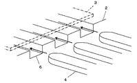
【解決手段】XYステージ2を最終の露光位置からアンローディング位置Uへ移動させると、ここに待機していた排出用搬送ロボットのアーム4がXYステージ2の溝部6に差し込まれ、このアーム4を上昇させることにより基板3が持ち上げられてXYステージ2から排出される。XYステージ2はローディング位置Lへ移動し、未露光の基板を保持する供給用搬送ロボットのアームが下降してXYステージ2の溝部6に上方から挿入され、未露光の基板がXYステージ2上に供給される。
【選択図】図1Provided is a substrate supply / discharge method in an exposure apparatus that can supply / discharge a substrate in a short time.
When an XY stage 2 is moved from a final exposure position to an unloading position U, an arm 4 of a discharge transfer robot waiting here is inserted into a groove portion 6 of the XY stage 2, and the arm 4 is moved. By raising, the substrate 3 is lifted and discharged from the XY stage 2. The XY stage 2 moves to the loading position L, the arm of the transport robot for holding the unexposed substrate is lowered, and is inserted into the groove 6 of the XY stage 2 from above, and the unexposed substrate is placed on the XY stage 2. Supplied.
[Selection] Figure 1
Description
この発明は、露光装置における基板の給排方法に係り、特に大型基板を露光装置に供給し且つ露光装置から排出する方法に関する。 The present invention relates to a substrate supply / discharge method in an exposure apparatus, and more particularly to a method of supplying a large substrate to the exposure apparatus and discharging it from the exposure apparatus.
薄型、軽量で低消費電力等の特徴を有する液晶表示装置は、フラットパネルディスプレイとして広く使用されているが、TVやコンピュータのディスプレイへの適用に伴って、近年は画面の大型化が要求されている。
従来、このような液晶表示装置に用いられる液晶基板やカラーフィルタ等の基板にマスクのパターンを転写する際には、一回の露光で基板の全面上にパターンを焼き付ける一括露光が一般的であったが、基板の大型化に伴い、例えば特許文献1に開示されているように、基板の露光領域を複数に分割し、基板をXYステージ上に載置してマスクとの相対位置を変えながら逐次露光を行う分割逐次露光方式が多く採用されている。
Liquid crystal display devices that are thin, lightweight, and have low power consumption are widely used as flat panel displays. However, in recent years, with the application to TV and computer displays, there has been a demand for larger screens. Yes.
Conventionally, when a mask pattern is transferred to a substrate such as a liquid crystal substrate or a color filter used in such a liquid crystal display device, collective exposure in which the pattern is printed on the entire surface of the substrate in one exposure is generally performed. However, as the size of the substrate increases, for example, as disclosed in
この分割逐次露光方式により大型基板へのパターン転写が容易となったが、XYステージ上への基板の給排を行う必要があり、従来は、ローディング位置にXYステージを移動させ、XYステージ上に配設された昇降自在の複数のリフトピンを持ち上げた状態で、搬送ロボットのアーム上に保持された基板をリフトピンの上に載置し、アームを退避させた後にリフトピンを下降させることにより基板をXYステージ上に供給していた。また、基板の排出時にも、アンローディング位置にXYステージを移動させ、リフトピンを基板と共に持ち上げ、この状態で搬送ロボットのアームを基板の下に伸ばした後、アームを上昇させてXYステージから基板を排出していた。 This divided sequential exposure method facilitates pattern transfer to a large substrate. However, it is necessary to supply and discharge the substrate on the XY stage. Conventionally, the XY stage is moved to the loading position and then moved onto the XY stage. The substrate held on the arm of the transfer robot is placed on the lift pin in the state where the plurality of liftable lift pins arranged are lifted, and the substrate is moved to the XY by lowering the lift pin after retracting the arm. It was supplied on stage. Also, when the substrate is discharged, the XY stage is moved to the unloading position, the lift pins are lifted together with the substrate, the arm of the transfer robot is extended under the substrate in this state, and then the arm is lifted to remove the substrate from the XY stage. It was discharged.
このようにリフトピンによる基板の昇降動作を必要としたため、XYステージ上への基板の給排動作に時間を要するという問題点があった。
この発明は、このような従来の問題点を解消するためになされたもので、短時間で基板を給排することができる露光装置における基板の給排方法を提供することを目的とする。
Thus, since the raising / lowering operation | movement of the board | substrate by a lift pin was required, there existed a problem that time required for the board | substrate supply-and-discharge operation | movement to an XY stage.
An object of the present invention is to provide a substrate supply / discharge method in an exposure apparatus that can supply / discharge a substrate in a short time.
この発明に係る露光装置における基板の給排方法は、ローディング位置のXYステージ上に基板を供給し、XYステージを基板と共に最初の露光位置へ移動させて露光し、最終の露光位置まで順次XYステージを移動させて逐次露光し、XYステージをアンローディング位置へ移動させてXYステージ上から基板を排出する露光装置において、XYステージ上に搬送ロボットのアームが収容される溝部を形成し、基板を載せた搬送ロボットのアームを上方からローディング位置のXYステージの溝部に下降させて基板をXYステージ上に供給し、アンローディング位置に搬送ロボットのアームを待機させた状態で基板を載せたXYステージを搬送ロボットのアームの延長方向からアンローディング位置へ移動させることによりXYステージの溝部に搬送ロボットのアームを差し込み、搬送ロボットのアームを上昇させることによりXYステージから基板を排出する方法である。 In the exposure apparatus according to the present invention, the substrate supply / discharge method supplies the substrate onto the XY stage at the loading position, moves the XY stage together with the substrate to the first exposure position, performs exposure, and sequentially advances to the final exposure position. In the exposure apparatus that moves the XY stage to the unloading position and moves the XY stage to the unloading position, a groove for accommodating the arm of the transfer robot is formed on the XY stage, and the substrate is placed on the XY stage. The arm of the transfer robot is lowered from above to the groove of the XY stage at the loading position to supply the substrate onto the XY stage, and the XY stage on which the substrate is placed is transferred to the unloading position while the arm of the transfer robot is waiting. By moving the robot arm from the extension direction to the unloading position, Insert the arm of the transport robot parts, a method for discharging the substrate from the XY stage by raising the arms of the transfer robot.
好ましくは、最終の露光位置から直線的にアンローディング位置へ移動させることによりXYステージの溝部に搬送ロボットのアームが差し込まれる。
また、ローディング位置から直線的に最初の露光位置へ移動させることによりXYステージの溝部から搬送ロボットのアームが引き抜かれることが好ましい。
さらに、ローディング位置とアンローディング位置とを互いに並んで配置し、アンローディング位置で搬送ロボットのアームを上昇させてXYステージから基板を排出した後、XYステージをアンローディング位置へ移動させると同時に、排出した基板を保持する搬送ロボットのアームをアンローディング位置とは反対方向へ移動させることが好ましい。
Preferably, the arm of the transfer robot is inserted into the groove portion of the XY stage by linearly moving from the final exposure position to the unloading position.
Further, it is preferable that the arm of the transfer robot is pulled out from the groove portion of the XY stage by linearly moving from the loading position to the first exposure position.
Furthermore, the loading position and the unloading position are arranged side by side, the arm of the transfer robot is raised at the unloading position and the substrate is discharged from the XY stage, and then the XY stage is moved to the unloading position and discharged at the same time. It is preferable to move the arm of the transfer robot holding the substrate in the direction opposite to the unloading position.
この発明によれば、基板を載せた搬送ロボットのアームを上方からXYステージの溝部に下降させることにより基板をXYステージ上に供給し、基板を載せたXYステージをアンローディング位置へ移動させることにより、ここに待機していた搬送ロボットのアームをXYステージの溝部に差し込み、その後アームを上昇させることでXYステージから基板を排出するので、従来のようなリフトピンによる基板の昇降動作が不要となり、短時間で基板を給排することが可能となる。 According to this invention, the substrate is supplied onto the XY stage by lowering the arm of the transfer robot carrying the substrate from above to the groove portion of the XY stage, and the XY stage on which the substrate is placed is moved to the unloading position. Since the arm of the transfer robot waiting here is inserted into the groove portion of the XY stage and then the arm is lifted, the substrate is discharged from the XY stage. It becomes possible to supply and discharge the substrate in time.
以下、この発明の実施の形態を添付図面に基づいて説明する。
図1にこの発明の実施の形態で用いられる露光装置の定盤を示す。定盤1の表面上にX方向及びY方向に移動自在にXYステージ2が配置されている。定盤1上には、XYステージ2に基板3が供給されるローディング位置LとXYステージ2から基板3が排出されるアンローディング位置Uとが互いに並んで画定されており、アンローディング位置Uに排出用搬送ロボットのアーム4が待機している。図1では示されていないが、ローディング位置Lの近傍には供給用搬送ロボットのアームが配置されている。また、定盤1の上方には、基板3にパターンを転写するためのマスク5が固定されている。
Embodiments of the present invention will be described below with reference to the accompanying drawings.
FIG. 1 shows a surface plate of an exposure apparatus used in the embodiment of the present invention. An
なお、基板3の露光領域は複数に分割され、基板3をXYステージ2上に載置して最初の露光位置から最後の露光位置まで順次XYステージ2を移動させて逐次露光が行われるが、ローディング位置L及びアンローディング位置Uから+Y軸方向に所定距離だけ離れた位置にそれぞれ最初の露光位置及び最後の露光位置が設定されている。
In addition, although the exposure area | region of the board |
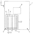
XYステージ2の表面上には、搬送ロボットのアーム4に対応した互いに平行な複数の溝部6が形成されている。これらの溝部6は、図2に示されるように、XYステージ2上に基板3を載置した状態で搬送ロボットの対応するアーム4が自由に差し込まれて収容されるような大きさを有している。
On the surface of the
次に、この実施の形態に係る基板の給排方法について説明する。まず、基板3を載置したXYステージ2を最初の露光位置から最終の露光位置まで順次移動させて逐次露光を行う。また、図1に示されるように、排出用搬送ロボットのアーム4をアンローディング位置Uに待機させておく。基板3の露光処理を完了した後、XYステージ2を最終の露光位置から−Y軸方向へ移動させる。このとき、アンローディング位置Uから+Y軸方向に所定距離だけ離れた位置に最後の露光位置が設定されているため、XYステージ2を−Y軸方向へ移動させると、アンローディング位置Uに待機していた排出用搬送ロボットのアーム4がXYステージ2の溝部6に次第に差し込まれる。
Next, a substrate supply / discharge method according to this embodiment will be described. First, the
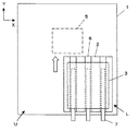
図3に示されるように、XYステージ2がアンローディング位置Uまで移動すると、排出用搬送ロボットのアーム4を上昇させることにより、アーム4がXYステージ2の溝部6から上方へ離れ、アーム4によって基板3が持ち上げられる。このようにして露光済みの基板3がXYステージ2から排出されると、図4に示されるように、排出用搬送ロボットのアーム4が基板3と共に−X軸方向、すなわちローディング位置Lとは反対方向に移動して基板3が次工程へ搬送される。この排出用搬送ロボットのアーム4の移動と同時にXYステージ2が+X軸方向、すなわちローディング位置Lへ向けて移動すると共に供給用搬送ロボットのアーム7により未露光の基板3がローディング位置Lの上方へ搬送される。
As shown in FIG. 3, when the
そして、図5に示されるように、XYステージ2がローディング位置Lに到達し、供給用搬送ロボットのアーム7に保持された未露光の基板3がローディング位置Lの直上に到達すると、供給用搬送ロボットのアーム7が未露光の基板3と共に下降される。このとき、アーム7がそれぞれ対応するXYステージ2の溝部6に上方から挿入され、未露光の基板3がXYステージ2上に載置される。
Then, as shown in FIG. 5, when the
このようにしてXYステージ2へ未露光の基板3が供給されると、XYステージ2が最初の露光位置に到達するまで+Y軸方向へ移動し、最初の露光位置において基板3への露光が開始される。また、XYステージ2が+Y軸方向へ移動することで、自動的に供給用搬送ロボットのアーム7がXYステージ2の溝部6から引き抜かれ、供給用搬送ロボットのアーム7は次の未露光の基板を受け取るために移動することができる。
When the
以上のように、XYステージ2の溝部6に排出用搬送ロボットのアーム4あるいは供給用搬送ロボットのアーム7が収容される構成としたので、従来使用されていたリフトピンによる基板の昇降動作が不要となり、迅速に基板を給排することが可能となる。
また、ローディング位置L及びアンローディング位置Uから+Y軸方向に所定距離だけ離れた位置にそれぞれ最初の露光位置及び最後の露光位置が設定されているので、XYステージ2を1軸移動によってローディング位置Lから最初の露光位置まで、並びに最後の露光位置からアンローディング位置Uまで基板3を搬送することができ、極めて短い時間で露光処理を行うことができる。
As described above, since the
Further, since the first exposure position and the last exposure position are set at positions that are separated from the loading position L and the unloading position U by a predetermined distance in the + Y-axis direction, the loading position L is moved by moving the
1 定盤、2 XYステージ、3 基板、4 排出用搬送ロボットのアーム、5 マスク、6 溝部、7 供給用搬送ロボットのアーム。 1 Surface plate, 2 XY stage, 3 Substrate, 4 Discharge transfer robot arm, 5 Mask, 6 Groove, 7 Supply transfer robot arm.
Claims (4)
XYステージ上に搬送ロボットのアームが収容される溝部を形成し、
基板を載せた搬送ロボットのアームを上方からローディング位置のXYステージの溝部に下降させて基板をXYステージ上に供給し、
アンローディング位置に搬送ロボットのアームを待機させた状態で基板を載せたXYステージを搬送ロボットのアームの延長方向からアンローディング位置へ移動させることによりXYステージの溝部に搬送ロボットのアームを差し込み、
搬送ロボットのアームを上昇させることによりXYステージから基板を排出する
ことを特徴とする露光装置における基板の給排方法。 The substrate is supplied onto the XY stage at the loading position, the XY stage is moved to the first exposure position together with the substrate for exposure, the XY stage is sequentially moved to the final exposure position, and the XY stage is unloaded at the sequential exposure position. In an exposure apparatus that moves to the XY stage and ejects the substrate from the XY stage,
Forming a groove for accommodating the arm of the transfer robot on the XY stage,
Lower the arm of the transfer robot carrying the substrate from above to the groove of the XY stage at the loading position, and supply the substrate onto the XY stage.
By moving the XY stage on which the substrate is placed in the unloading position while waiting for the arm of the transfer robot from the extension direction of the transfer robot arm to the unloading position, the arm of the transfer robot is inserted into the groove portion of the XY stage,
A substrate supply / discharge method in an exposure apparatus, wherein the substrate is discharged from an XY stage by raising an arm of a transfer robot.
アンローディング位置で搬送ロボットのアームを上昇させてXYステージから基板を排出した後、XYステージをアンローディング位置へ移動させると同時に、排出した基板を保持する搬送ロボットのアームをアンローディング位置とは反対方向へ移動させる請求項1〜3のいずれか一項に記載の方法。 The loading position and the unloading position are arranged side by side,
After lifting the arm of the transfer robot at the unloading position and discharging the substrate from the XY stage, the XY stage is moved to the unloading position, and at the same time, the arm of the transfer robot holding the discharged substrate is opposite to the unloading position. The method according to claim 1, wherein the method is moved in a direction.
Priority Applications (1)
| Application Number | Priority Date | Filing Date | Title |
|---|---|---|---|
| JP2004110147A JP2005292645A (en) | 2004-04-02 | 2004-04-02 | Substrate supply / discharge method in exposure apparatus |
Applications Claiming Priority (1)
| Application Number | Priority Date | Filing Date | Title |
|---|---|---|---|
| JP2004110147A JP2005292645A (en) | 2004-04-02 | 2004-04-02 | Substrate supply / discharge method in exposure apparatus |
Publications (1)
| Publication Number | Publication Date |
|---|---|
| JP2005292645A true JP2005292645A (en) | 2005-10-20 |
Family
ID=35325606
Family Applications (1)
| Application Number | Title | Priority Date | Filing Date |
|---|---|---|---|
| JP2004110147A Pending JP2005292645A (en) | 2004-04-02 | 2004-04-02 | Substrate supply / discharge method in exposure apparatus |
Country Status (1)
| Country | Link |
|---|---|
| JP (1) | JP2005292645A (en) |
Cited By (5)
| Publication number | Priority date | Publication date | Assignee | Title |
|---|---|---|---|---|
| JP2008058504A (en) * | 2006-08-30 | 2008-03-13 | Dainippon Printing Co Ltd | Filter exposure equipment |
| JP2013512552A (en) * | 2009-11-27 | 2013-04-11 | 株式会社ニコン | Substrate transport apparatus, substrate transport method, substrate support member, substrate holding apparatus, exposure apparatus, exposure method, and device manufacturing method |
| JP2013524259A (en) * | 2010-04-01 | 2013-06-17 | 株式会社ニコン | Exposure apparatus, object replacement method, exposure method, and device manufacturing method |
| KR101354122B1 (en) | 2006-08-09 | 2014-01-27 | 엘아이지에이디피 주식회사 | Loadign and unloading device for substarate, and the method thereof |
| KR20240169506A (en) | 2023-05-24 | 2024-12-03 | 캐논 가부시끼가이샤 | Substrate processing apparatus, control method, and article manufacturing method |
-
2004
- 2004-04-02 JP JP2004110147A patent/JP2005292645A/en active Pending
Cited By (8)
| Publication number | Priority date | Publication date | Assignee | Title |
|---|---|---|---|---|
| KR101354122B1 (en) | 2006-08-09 | 2014-01-27 | 엘아이지에이디피 주식회사 | Loadign and unloading device for substarate, and the method thereof |
| JP2008058504A (en) * | 2006-08-30 | 2008-03-13 | Dainippon Printing Co Ltd | Filter exposure equipment |
| JP2013512552A (en) * | 2009-11-27 | 2013-04-11 | 株式会社ニコン | Substrate transport apparatus, substrate transport method, substrate support member, substrate holding apparatus, exposure apparatus, exposure method, and device manufacturing method |
| JP2013524259A (en) * | 2010-04-01 | 2013-06-17 | 株式会社ニコン | Exposure apparatus, object replacement method, exposure method, and device manufacturing method |
| KR20240169506A (en) | 2023-05-24 | 2024-12-03 | 캐논 가부시끼가이샤 | Substrate processing apparatus, control method, and article manufacturing method |
| JP2024168774A (en) * | 2023-05-24 | 2024-12-05 | キヤノン株式会社 | SUBSTRATE PROCESSING APPARATUS, CONTROL METHOD, AND ARTICLE MANUFACTURING METHOD |
| JP7625636B2 (en) | 2023-05-24 | 2025-02-03 | キヤノン株式会社 | SUBSTRATE PROCESSING APPARATUS, CONTROL METHOD, AND ARTICLE MANUFACTURING METHOD |
| KR20260002475A (en) | 2023-05-24 | 2026-01-06 | 캐논 가부시끼가이샤 | Substrate processing apparatus, control method, and article manufacturing method |
Similar Documents
| Publication | Publication Date | Title |
|---|---|---|
| JP5317858B2 (en) | Backup pin placement method, placement device, electronic component processing method, and electronic component placement device | |
| WO2016199207A1 (en) | Printing device and substrate-working device | |
| JPWO2018105016A1 (en) | Printing device and storage device | |
| JP4854725B2 (en) | Cluster device for substrate processing and substrate processing method for cluster device | |
| JP5720186B2 (en) | Workpiece transfer device | |
| JP2010034309A (en) | Coating apparatus and substrate processing system | |
| JP2003188593A (en) | Method for mounting electronic part | |
| JP2005292645A (en) | Substrate supply / discharge method in exposure apparatus | |
| JP5720201B2 (en) | Workpiece transfer device | |
| JP2009165942A (en) | Substrate processing apparatus and method | |
| CN111244020A (en) | Substrate holding apparatus, substrate processing apparatus, and substrate holding method | |
| JP5182278B2 (en) | Screen printing apparatus, component mounting system, and board supply method in component mounting system | |
| JP2012004209A (en) | Electronic component mounting method, electronic component mounting device, and backup pin arrangement method | |
| JP6546697B2 (en) | Substrate support apparatus, screen printing apparatus, coating apparatus, surface mounter, and backup pin setup method | |
| KR101057355B1 (en) | Substrate Floating Unit, Substrate Transfer Device And Coating Device With The Same | |
| KR101859279B1 (en) | Substrate processing apparatus and substrate processing method | |
| KR20110081494A (en) | Substrate Transfer Device | |
| TWI481540B (en) | Coating device and coating method | |
| JP2006312304A (en) | Printing apparatus and printing method | |
| KR101176231B1 (en) | Heat and cooling treatment apparatus substrate treatment apparatus and substrate treatment method | |
| JP2013102153A (en) | Processing stage device and coating processor using the same | |
| JP2001272520A (en) | Device for coloring of color filter | |
| US7367725B2 (en) | Method for removing developing solution | |
| JP6131077B2 (en) | Transfer peeling apparatus, transfer peeling method and pattern forming system | |
| JP4458694B2 (en) | Substrate transport apparatus and exposure apparatus |