JP2005292375A - Audio-reproducing device and clock-frequency control method - Google Patents
Audio-reproducing device and clock-frequency control method Download PDFInfo
- Publication number
- JP2005292375A JP2005292375A JP2004105755A JP2004105755A JP2005292375A JP 2005292375 A JP2005292375 A JP 2005292375A JP 2004105755 A JP2004105755 A JP 2004105755A JP 2004105755 A JP2004105755 A JP 2004105755A JP 2005292375 A JP2005292375 A JP 2005292375A
- Authority
- JP
- Japan
- Prior art keywords
- clock
- control
- audio
- audio data
- buffer
- Prior art date
- Legal status (The legal status is an assumption and is not a legal conclusion. Google has not performed a legal analysis and makes no representation as to the accuracy of the status listed.)
- Granted
Links
- 238000000034 method Methods 0.000 title claims description 30
- 239000000872 buffer Substances 0.000 claims abstract description 61
- 238000012545 processing Methods 0.000 claims abstract description 14
- 230000005236 sound signal Effects 0.000 claims abstract description 10
- 230000003139 buffering effect Effects 0.000 claims description 2
- 238000012544 monitoring process Methods 0.000 claims 1
- 238000012546 transfer Methods 0.000 abstract description 15
- 230000007423 decrease Effects 0.000 abstract description 8
- 230000001360 synchronised effect Effects 0.000 abstract description 4
- 238000010586 diagram Methods 0.000 description 7
- 230000003247 decreasing effect Effects 0.000 description 4
- 238000012790 confirmation Methods 0.000 description 2
- 230000008929 regeneration Effects 0.000 description 2
- 238000011069 regeneration method Methods 0.000 description 2
- 238000001994 activation Methods 0.000 description 1
- 230000005540 biological transmission Effects 0.000 description 1
- 230000000593 degrading effect Effects 0.000 description 1
- 238000005259 measurement Methods 0.000 description 1
- 230000008092 positive effect Effects 0.000 description 1
- 230000001172 regenerating effect Effects 0.000 description 1
- 238000005070 sampling Methods 0.000 description 1
Images


Landscapes
- Information Transfer Systems (AREA)
- Signal Processing For Digital Recording And Reproducing (AREA)
Abstract
Description
この発明は、外部装置から入力されるオーディオデータを、外部装置と同期して再生するオーディオ再生装置およびクロック周波数制御方法に関するものである。 The present invention relates to an audio reproducing apparatus and a clock frequency control method for reproducing audio data input from an external apparatus in synchronization with the external apparatus.
パーソナルコンピュータとオーディオ再生装置をUSBインタフェースで接続し、パーソナルコンピュータが発生または読み出したオーディオデータをオーディオ再生装置で再生するいわゆるUSBオーディオが実用化されている。 A so-called USB audio in which a personal computer and an audio reproduction device are connected by a USB interface and audio data generated or read by the personal computer is reproduced by the audio reproduction device has been put into practical use.
パーソナルコンピュータとオーディオ再生装置は、それぞれ独立した別の装置であるため、それぞれが内部のクロックで動作する。両者のクロック周波数が完全に一致していることは稀であり、もしオーディオ再生装置のクロックがパーソナルコンピュータのクロックよりも遅ければ、オーディオ再生装置のバッファがオーバーフローしてしまい、もしオーディオ再生装置のクロックがパーソナルコンピュータのクロックよりも速ければ、オーディオ再生装置のバッファがアンダーランしてしまう。 Since the personal computer and the audio playback device are separate and independent devices, each operates with an internal clock. It is rare that the clock frequencies of the two are exactly the same, and if the audio playback device clock is slower than the personal computer clock, the audio playback device buffer overflows, and the audio playback device clock. If it is faster than the clock of the personal computer, the buffer of the audio playback device will underrun.
このため、パーソナルコンピュータとオーディオ再生装置のクロックを同期させる必要があるが、USBオーディオでは、一般的にオーディオ再生装置(デバイス)側の再生クロックを調節してパーソナルコンピュータ(ホスト)側に同期させる適応型の同期制御を行っている(たとえば特許文献1)。 For this reason, it is necessary to synchronize the clocks of the personal computer and the audio playback device. However, in the case of USB audio, it is generally adapted to adjust the playback clock on the audio playback device (device) side to synchronize with the personal computer (host) side. Mold synchronization control is performed (for example, Patent Document 1).
特許文献1の装置は、コンピュータ1とオーディオ再生装置2をUSB1.1規格のケーブルで接続し、コンピュータ1からオーディオデータを受信する毎(1m秒毎)に、バッファ(FIFO)の残量をチェックしてクロック周波数の制御を行うものである。
特許文献1の装置は、USB1.1規格のインタフェースで接続しているため、ホストからデバイスへのデータ送信は、1m秒毎であった。しかし、現在主流となりつつあるUSB2.0規格では、その8倍の125μ秒毎にホストからデバイスへデータ送信が行われる。
Since the apparatus of
従来と同様にパーソナルコンピュータからオーディオデータが送信されてくる毎に、オーディオ再生装置において、バッファ残量チェックと再生クロックの制御を行えば、高精度のクロック周波数制御が可能になり、音質に良い影響を与えることは確かである。しかしながら、オーディオ再生装置のCPUは、再生クロックの制御のみならず、表示制御など他のタスクを処理しなければならないため、125μ秒毎の再生クロック制御の負担が大きく、装置全体の動作性能(パフォーマンス)を低下させてしまうという問題点があった。 Every time audio data is sent from a personal computer as before, if the remaining amount of buffer is checked and the playback clock is controlled in the audio playback device, high-accuracy clock frequency control is possible, which has a positive effect on sound quality. Is certain to give. However, since the CPU of the audio playback device has to process not only the control of the playback clock but also other tasks such as display control, the burden of playback clock control every 125 μs is heavy, and the overall performance of the device (performance) ) Is reduced.
この発明は、CPUの負荷に合わせて同期制御の間隔を変更することにより、上記課題を解決したオーディオ再生装置およびクロック周波数制御方法を提供することを目的とする。 An object of the present invention is to provide an audio reproducing apparatus and a clock frequency control method that solve the above-mentioned problems by changing the synchronization control interval according to the load of the CPU.
この発明は、外部装置から所定の割込間隔で定期的に送信されてくるオーディオデータを受信する受信手段と、前記受信手段が受信したオーディオデータをバッファするとともに、このオーディオデータを所定の再生クロックで読み出してアナログのオーディオ信号に変換する再生手段と、制御手段とを備え、前記制御手段は、前記オーディオデータが送信されてくるタイミングに同期して、前記バッファの残量をチェックし、この残量が所定範囲を外れないように前記再生クロックの周波数を制御するクロック制御処理と、自己の負荷を監視し、この負荷に応じて前記クロック制御処理を実行する間隔を前記割込間隔の1倍ないしn倍(nは正の整数)の間で切り換える制御間隔設定処理と、を実行することを特徴とする。 The present invention provides a receiving means for receiving audio data periodically transmitted from an external device at a predetermined interrupt interval, and buffering the audio data received by the receiving means, Reproducing means for reading out and converting into an analog audio signal, and a control means. The control means checks the remaining capacity of the buffer in synchronization with the timing at which the audio data is transmitted, and A clock control process for controlling the frequency of the recovered clock so that the amount does not deviate from the predetermined range, and its own load is monitored, and the interval for executing the clock control process according to this load is one time the interrupt interval. Or a control interval setting process for switching between n times (n is a positive integer).
この発明は、外部装置から所定の割込間隔で定期的に送信されてくるオーディオデータを所定の再生クロックで読み出してアナログのオーディオ信号に変換する再生手順と、前記オーディオデータが送信されてくるタイミングに同期して、前記バッファの残量をチェックし、この残量が所定範囲を外れないように前記再生クロックの周波数を制御するクロック制御手順と、CPUの負荷を監視し、この負荷に応じて前記クロック制御手順を前記割込間隔の1倍ないしn倍(nは正の整数)の間で切り換える制御間隔設定手順と、を有することを特徴とする。 The present invention provides a reproduction procedure for reading audio data periodically transmitted from an external device at a predetermined interrupt interval with a predetermined reproduction clock and converting it into an analog audio signal, and a timing at which the audio data is transmitted. In synchronization with this, the remaining amount of the buffer is checked, the clock control procedure for controlling the frequency of the reproduction clock so that the remaining amount does not deviate from the predetermined range, and the load on the CPU are monitored. And a control interval setting procedure for switching the clock control procedure between 1 and n times the interrupt interval (n is a positive integer).
この発明では、外部装置から定期的に送信されてくるオーディオデータを受信して、これを所定の再生クロックで読み出してアナログのオーディオ信号に変換する。所定の再生クロックは、外部装置のクロックと同期させるべく周波数を設定するが、外部装置のクロックと完全に同期させることは困難である。そこで、オーディオデータを再生しながら、継続的にクロック周波数の制御を行う。再生クロックは、一般的に高周波の基本クロックを分周して発生し、分周比(分周カウンタのカウントアップ値)を変更することで周波数を調節するため、周波数制御が段階的であり、外部装置のクロック周波数と完全に一致させられない場合が多いからである。 In the present invention, audio data periodically transmitted from an external device is received, read out with a predetermined reproduction clock, and converted into an analog audio signal. The frequency of the predetermined reproduction clock is set to be synchronized with the clock of the external device, but it is difficult to completely synchronize with the clock of the external device. Therefore, the clock frequency is continuously controlled while reproducing the audio data. The regenerative clock is generally generated by dividing the high-frequency basic clock, and the frequency is adjusted by changing the division ratio (the count-up value of the division counter), so the frequency control is stepwise. This is because there are many cases where the clock frequency of the external device cannot be completely matched.
クロック周波数の制御は、受信したオーディオデータを再生するまでバッファするバッファの残量をチェックし、残量が減少傾向であれば再生クロックが速すぎると判断し、残量が増加傾向であれば再生クロックが遅すぎると判断する。そして、この判断に基づいて再生クロックの周波数を制御する。たとえば、USB2.0の場合外部装置(ホスト)からオーディオ再生装置(デバイス)へ125μ秒毎に割り込みをかけてデータを送信するが、このデータの送信毎に再生クロックを制御していたのでは、CPU負荷が大きい場合に装置全体のパフォーマンスが低下してしまう場合がある。 The clock frequency is controlled by checking the remaining buffer capacity until the received audio data is played back. If the remaining volume is decreasing, it is determined that the playback clock is too fast. Judge that the clock is too slow. Based on this determination, the frequency of the recovered clock is controlled. For example, in the case of USB 2.0, an interrupt is sent every 125 μs from an external device (host) to an audio playback device (device), and the playback clock is controlled each time this data is transmitted. When the CPU load is large, the performance of the entire apparatus may be degraded.
この発明では、CPUの負荷を監視し、負荷が大きいときは、その負荷に応じて再生クロックの制御間隔を伸ばすようにした。たとえば、USB2.0の場合、通常は、外部装置からデータが送られてきたときの割り込み(受信割り込み)1回毎(125μ秒毎)に再生クロックの制御を行っているが、CPU負荷が大きいときは、その大きさに応じて2回毎(250μ秒毎)、4回毎(500μ秒毎)、8回毎(1m秒毎)に変更する。これにより、CPUの負荷に応じて可能な範囲で頻繁に再生クロックの制御を行うことができ、装置全体のパフォーマンスを低下させることなく音質の向上を図ることができる。 In the present invention, the CPU load is monitored, and when the load is large, the control interval of the reproduction clock is extended in accordance with the load. For example, in the case of USB 2.0, the reproduction clock is normally controlled every time an interrupt (reception interrupt) occurs when data is sent from an external device (every 125 μs), but the CPU load is heavy. Sometimes, it is changed every 2 times (every 250 μs), every 4 times (every 500 μs), and every 8 times (every 1 ms) according to the size. As a result, the reproduction clock can be frequently controlled within a possible range in accordance with the CPU load, and the sound quality can be improved without degrading the performance of the entire apparatus.
この発明によれば、CPUの負荷に応じて同期制御の間隔を動的に変化させることができるため、装置の総合的なパフォーマンスを高く保ちつつ、再生するオーディオ信号の音質を向上させることができる。 According to the present invention, since the synchronization control interval can be dynamically changed according to the CPU load, the sound quality of the reproduced audio signal can be improved while keeping the overall performance of the apparatus high. .
図面を参照してこの発明の実施形態について説明する。
図1はこの発明が適用されるUSBオーディオシステムの構成図である。このオーディオシステムは、コンピュータ1、オーディオ再生装置2、および両者を接続するUSBケーブル3を有している。コンピュータ1は、オーディオデータを発生または読み出し、このデータをUSBケーブル3を介してオーディオ再生装置2に送信する。オーディオ再生装置2は、このオーディオデータを受信してアナログのオーディオ信号に変換し、このオーディオ信号をスピーカ等を介して放音する。この実施形態では、コンピュータ1(ホスト)とオーディオ再生装置2(デバイス)は、USB2.0規格のインタフェースで接続されており、コンピュータ1からオーディオ再生装置2へのデータ転送割り込みは125μ秒毎に発生する。
Embodiments of the present invention will be described with reference to the drawings.
FIG. 1 is a block diagram of a USB audio system to which the present invention is applied. This audio system has a
デバイスであるオーディオ再生装置2は、ホストであるコンピュータ1と、互いのシステムクロックの誤差を補償してオーディオデータの転送と再生の同期をとるため、受信したデータをバッファするバッファの残量をチェックし、バッファ残量が減少傾向にあればクロック周波数を遅く(クロック周期を長く)制御し、バッファ残量が増加傾向にあればクロック周波数を速く(クロック周期を短く)制御する。
The
図2はオーディオ再生装置2の制御処理系のブロック図である。USBインタフェース10には、受信バッファ11が接続されている。また、CPU12には、この受信バッファ11および再生バッファ13が接続されている。CPU12は、受信バッファ11のデータを再生バッファ13に転送する。再生バッファ13に転送されたデータは、D/Aコンバータ14によって読み出され、アナログのオーディオ信号に変換される。D/Aコンバータ14による再生バッファ13のデータ読み出しは、クロック発生回路15が発生するクロック信号(サンプリングクロック)にしたがって行われる。クロック発生回路15が発生するクロック信号の周波数(周期)は、CPU12によって、ホストであるコンピュータ1のクロックに同期するように制御される。
FIG. 2 is a block diagram of a control processing system of the
受信バッファはFIFOであり、USBインタフェース10がコンピュータ1から受信したオーディオデータを書き込み、CPU12が書き込まれた順にこのデータを読み出す。USBインタフェース10は、コンピュータ1からパケットを受信すると、このパケットに含まれている1フレーム分のオーディオデータを受信バッファ11に書き込むとともに、CPU12に対して割り込み(受信割り込み)をかける。
The reception buffer is a FIFO, and the
CPU12は、USBインタフェース10から受信割り込みがあると、受信バッファ11に書き込まれたオーディオデータを書き込み順に読み出して再生バッファ13に転送する。この転送を行う前に、再生バッファ13の残量をチェックし、その増減の程度に応じてクロック発生回路15のクロック周波数を制御する。CPU12は、このクロック周波数制御およびデータ転送からなる「再生制御処理」を、通常は、上記受信割り込みがある毎(125μ秒毎)に実行するが、他のタスクの実行中で負荷が大きいときは、受信割り込み2回毎(250μ秒毎)、4回毎(500μ秒毎)、8回毎(1m秒毎)に制御間隔を広げて実行する。
When receiving a reception interrupt from the
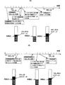
図3を参照してこのオーディオ再生装置2におけるクロック周波数の制御について説明する。コンピュータ1側のクロックよりもオーディオ再生装置2の再生クロックが遅い場合には、再生バッファ13の残量が徐々に増加してゆく。この状態で、バッファ残量が上限しきい値に達したとき、クロック周期(分周カウンタのカウントアップ値)を1減らしてクロック周波数を上昇させる。これにより、再生バッファ13から読み出されるデータ量が増加することにより、再生バッファ13の残量増加を解消する。
The control of the clock frequency in the
一方、コンピュータ1側のクロックよりもオーディオ再生装置2の再生クロックが速い場合には、再生バッファ13の残量が徐々に減少してゆく。この状態で、バッファ残量が下限しきい値に達したとき、クロック周期(分周カウンタのカウントアップ値)を1増やしてクロック周波数を低下させる。これにより、再生バッファ13から読み出されるデータ量が減少することにより、再生バッファ13の残量減少を解消する。
On the other hand, when the reproduction clock of the
なお、クロック周期(分周カウンタのカウントアップ値)を1増減しても再生バッファ13の減少・減少が解消しないときは、さらに1増減するようにしてもよい。
If the decrease / decrease of the
図4を参照してCPUの負荷算出および制御間隔設定動作について説明する。CPU12は、処理待ちタスクを順次または割り込みで処理するとともに、100μ秒のタイマ割り込みを用いて、そのとき実行されているタスクを確認(記録)する動作を行う。100回の割り込み(10m秒)毎に、100回の割り込みタイミングにおいて、実際の処理を実行する(アイドルタスク以外の)タスクが何回確認されたかで負荷(負荷率(%))を算出する。すなわち、実際の処理を実行するタスクが確認された回数が負荷率(%)とされる。
The CPU load calculation and control interval setting operation will be described with reference to FIG. The
100回の割り込みで負荷率を算出することで、実際のタスクが確認された回数がそのままパーセントとなるようにしているが、100回以外の確認回数で負荷率(%)を算出する場合には、実際のタスクが確認された回数を全確認回数で割って100を乗じればよい。 By calculating the load factor with 100 interrupts, the number of times that the actual task has been confirmed is kept as a percentage, but when calculating the load factor (%) with the number of confirmations other than 100, The number of times the actual task is confirmed may be divided by the total number of confirmations and multiplied by 100.
同図(A)は、タスク処理動作を示すフローチャートである。通常のタスクおよび割り込みタスク(再生制御処理を含む)は、この処理で実行される。処理待ちタスクがある場合または割り込みが発生した場合にこの処理が実行される。まず、そのタスクの起動処理を行う(s1)。そして、このタスクの処理を実行する(s2)。所定の処理を実行したのち、このタスクの終了処理を行う(s3)。なお、このタスクが他のタスク(カレントタスク)に対して割り込みで実行される場合には、カレントタスク番号の保存と復帰が必要となり、その場合には、s1の処理でカレントタスク番号を保存し、s3の処理でカレントタスク番号を復帰させる。 FIG. 4A is a flowchart showing the task processing operation. Normal tasks and interrupt tasks (including playback control processing) are executed in this processing. This process is executed when there is a task waiting for processing or when an interrupt occurs. First, the task activation process is performed (s1). Then, the process of this task is executed (s2). After executing the predetermined process, the task end process is performed (s3). If this task is executed as an interrupt to another task (current task), it is necessary to save and restore the current task number. In this case, the current task number is saved in the process of s1. , S3 to restore the current task number.
図4(B)は、100μ秒毎の負荷測定のためのタイマ割り込み処理を示すフローチャートである。割り込みが発生すると、この割り込みによって割り込まれたタスクであるカレントタスクの番号またはIDなどの固有の数字を保存する(s5)。この固有の数字は100回の割り込みについて(10m秒間)、配列として蓄積記憶される。この処理を10m秒間繰り返し、10m秒が経過すると(s6)、上記配列に基づき実際のタスクの占める割合である負荷率を算出する(s7)。そして、この負荷率が前回から変化しているかを判断し(s8)、変化している場合には、この新たな負荷率で同図(C)に示す制御間隔テーブルを参照して制御間隔を決定し、この制御間隔係数Rを再生制御処理に指示して制御間隔を変更する(s9)。 FIG. 4B is a flowchart showing timer interrupt processing for load measurement every 100 μs. When an interrupt occurs, a unique number such as the current task number or ID interrupted by the interrupt is saved (s5). This unique number is stored and stored as an array for 100 interrupts (10 msec). This process is repeated for 10 msec. When 10 msec elapses (s6), a load factor that is a ratio of an actual task is calculated based on the above arrangement (s7). Then, it is determined whether or not the load factor has changed from the previous time (s8). If the load factor has changed, the control interval is determined by referring to the control interval table shown in FIG. The control interval coefficient R is determined and the regeneration control process is instructed to change the control interval (s9).
同図(C)は、制御間隔テーブルを示す図である。同図(B)の割り込み処理によって算出されたCPUの負荷が10%以下であった場合には、R=1すなわち125μ秒に制御間隔(再生制御処理を実行する間隔)を設定する。CPUの負荷が11%〜20%であった場合には、R=2すなわち250μ秒に制御間隔を設定する。CPUの負荷が21%〜30%であった場合には、R=4すなわち500μ秒に制御間隔を設定する。CPUの負荷が31%以上であった場合には、R=8すなわち1m秒に制御間隔を設定する。 FIG. 3C shows a control interval table. When the CPU load calculated by the interrupt process in FIG. 10B is 10% or less, the control interval (interval for executing the reproduction control process) is set to R = 1, that is, 125 μsec. When the CPU load is 11% to 20%, the control interval is set to R = 2, that is, 250 μsec. When the CPU load is 21% to 30%, the control interval is set to R = 4, that is, 500 μsec. When the CPU load is 31% or more, the control interval is set to R = 8, that is, 1 msec.
図5のフローチャートおよび図6、図7のオーディオデータの転送処理を説明する図を参照して、CPU12の再生制御処理を説明する。
図5のフローチャートにおいて、コンピュータ1からオーディオデータが送られてくると、まずこれを再生バッファ13に転送する(s11)。所定量の転送が終了すると、次に受信バッファ11に8フレーム分(8回の転送パケットで送られてくるデータ量)のオーディオデータを蓄積する(s12)。これだけデータが蓄積されたときオーディオの再生をスタートする(s13)。オーディオの再生は、D/Aコンバータ14が再生バッファ13のオーディオデータを読み出してアナログ信号として出力する動作である。
The playback control process of the
In the flowchart of FIG. 5, when audio data is sent from the
最初は、再生制御を実行する時間的間隔である制御間隔Rを1に設定する(s14)。すなわち、コンピュータ1からオーディオデータの受信がある毎(125μ秒毎)に再生制御を行うように設定する。そして、受信割り込みの回数をカウント(ダウンカウント)するカウンタiにR(最初は1)をセットする(s15)。 Initially, the control interval R, which is the time interval for executing the regeneration control, is set to 1 (s14). That is, it is set so that reproduction control is performed every time audio data is received from the computer 1 (every 125 μsec). Then, R (initially 1) is set to a counter i that counts (counts down) the number of reception interrupts (s15).
そして待機ルーチンで、受信割り込みの発生(s16)または、図4(B)の動作による制御間隔の変更の発生(s22)を監視する。 In the standby routine, the occurrence of a reception interrupt (s16) or the occurrence of a change in control interval due to the operation of FIG. 4B (s22) is monitored.
受信割り込みが発生すると(s16)、カウンタiを1減算する(s17)。これにより、i=0になれば、再生制御のタイミングになったとして以下の処理を実行する。 When a reception interrupt occurs (s16), the counter i is decremented by 1 (s17). As a result, when i = 0, it is determined that the playback control timing has come, and the following processing is executed.
まず、再生バッファ13の残量をチェックする(s19)。この再生バッファ13の残量に基づいて上述したクロック周波数の制御を行う(s20)。すなわち、再生バッファ13の残量が上側しきい値よりも多い場合には、再生クロックの周期を1だけ短くし、再生バッファの13の残量が下側しきい値よりも少ない場合には、再生クロックの周期を1だけ長くする。バッファ残量が上下しきい値の範囲であればクロック周期はそのままにする。こののち、Rフレーム分のデータを受信バッファ11から再生バッファ13に転送して(s21)、s15にもどる。
First, the remaining amount of the
制御間隔の変更が通知された場合(s22)には、この変更通知に合わせてRに1、2、4、8のいずれかを設定する(s23)。この設定変更は、その後の再生制御後のs15の動作で反映される。 When the change of the control interval is notified (s22), one of 1, 2, 4, and 8 is set in R according to the change notification (s23). This setting change is reflected in the operation of s15 after the subsequent reproduction control.
図6、図7を参照して受信バッファ11から再生バッファ13への転送について説明する。
図6は、500μ秒毎に受信バッファ11から再生バッファ13へオーディオデータの転送を行っているときの状態を示している。受信バッファ11に8フレーム分すなわち1000μ秒(1m秒)分のオーディオデータが蓄積されたのち、次の受信割り込みが発生したときに最初の500μ秒分のデータを再生バッファ13に向けて送信する。
The transfer from the
FIG. 6 shows a state in which audio data is transferred from the
一方、図7(A)は、制御間隔を125μ秒(R=1)から500μ秒(R=4)に変更したときのデータ転送動作を説明する図である。この図では、制御間隔が変更された次の受信割り込みタイミングにクロック周波数の制御を行ったのち4フレーム分のデータを送信し、以後、500μ秒毎に同様の処理を行う。なお、制御間隔が125μ秒から500μ秒に変更された最初の500μ秒間は、同図点線に示すように、受信割り込み毎に(受信クロックの制御を行わず)1フレーム分ずつのオーディオデータの転送のみ行うようにしてもよい。 On the other hand, FIG. 7A is a diagram for explaining the data transfer operation when the control interval is changed from 125 μsec (R = 1) to 500 μsec (R = 4). In this figure, the clock frequency is controlled at the next reception interrupt timing when the control interval is changed, and then data for four frames is transmitted, and thereafter the same processing is performed every 500 μsec. In the first 500 μsec when the control interval is changed from 125 μsec to 500 μsec, as shown by the dotted line in the figure, audio data is transferred for each frame (without receiving clock control) for each reception interrupt. May be performed only.
同図(B)は、制御間隔を500μ秒(R=4)から125μ秒(R=1)に変更したときのデータ転送動作を説明する図である。制御間隔が変更されると、次の(500μ秒毎の)制御タイミングに制御間隔を変更し、このとき再生バッファ13の残量チェックおよび再生クロックの周波数制御を行うとともに、1フレーム分のみのオーディオデータを受信バッファ11から再生バッファ13に転送する。このように、制御間隔が短く変更されても、(長い制御間隔の)次の制御タイミングが到来するまで制御間隔を長いまま維持するのは、直前の制御タイミングにこの長い制御間隔(500μ秒)分のデータを転送しているため、この長い制御間隔を経過しないと再生バッファ13の残量が同期点まで減少しないためである。
FIG. 5B is a diagram for explaining the data transfer operation when the control interval is changed from 500 μsec (R = 4) to 125 μsec (R = 1). When the control interval is changed, the control interval is changed to the next control timing (every 500 μs). At this time, the remaining amount of the
この実施形態では、制御間隔係数R=1、2、4、8と倍数で増加させるように制御しているが、制御間隔の変化はこのような倍数でなくてもよい。たとえば、R=1、2、3、4と等差的に増加させてもよい。 In this embodiment, control is performed such that the control interval coefficient R is increased by a multiple of R = 1, 2, 4, 8, but the change in the control interval may not be such a multiple. For example, R = 1, 2, 3, 4 may be increased equally.
1…コンピュータ
2…オーディオ再生装置
3…USBケーブル
10…USBインタフェース
11…受信バッファ
12…CPU
13…再生バッファ
14…D/Aコンバータ
15…クロック発生回路
DESCRIPTION OF
DESCRIPTION OF
Claims (2)
前記受信手段が受信したオーディオデータをバッファするとともに、このオーディオデータを所定の再生クロックで読み出してアナログのオーディオ信号に変換する再生手段と、
制御手段と、を備え、
前記制御手段は、前記オーディオデータが送信されてくるタイミングに同期して、前記バッファの残量をチェックし、この残量が所定範囲を外れないように前記再生クロックの周波数を制御するクロック制御処理と、
自己の負荷を監視し、この負荷に応じて前記クロック制御処理を実行する間隔を前記割込間隔の1倍ないしn倍(nは正の整数)の間で切り換える制御間隔設定処理と、を実行するオーディオ再生装置。 Receiving means for receiving audio data periodically transmitted from an external device at a predetermined interrupt interval;
Reproducing means for buffering the audio data received by the receiving means and for reading out the audio data with a predetermined reproduction clock and converting it into an analog audio signal;
Control means,
The control means checks the remaining amount of the buffer in synchronization with the timing at which the audio data is transmitted, and controls the frequency of the reproduction clock so that the remaining amount does not deviate from the predetermined range. When,
Control interval setting processing that monitors its own load and switches the interval for executing the clock control processing between 1 to n times the interrupt interval (n is a positive integer) according to this load Audio playback device.
前記オーディオデータが送信されてくるタイミングに同期して、前記バッファの残量をチェックし、この残量が所定範囲を外れないように前記再生クロックの周波数を制御するクロック制御手順と、
CPUの負荷を監視し、この負荷に応じて前記クロック制御手順を実行する間隔を前記割込間隔の1倍ないしn倍(nは正の整数)の間で切り換える制御間隔設定手順と、
を有することを特徴とするクロック周波数制御方法。 A reproduction procedure for reading audio data periodically transmitted from an external device at a predetermined interrupt interval with a predetermined reproduction clock and converting it to an analog audio signal;
A clock control procedure for checking the remaining amount of the buffer in synchronization with the timing at which the audio data is transmitted, and controlling the frequency of the reproduction clock so that the remaining amount does not deviate from a predetermined range;
A control interval setting procedure for monitoring a load on the CPU and switching an interval for executing the clock control procedure according to the load between 1 to n times the interrupt interval (n is a positive integer);
A clock frequency control method comprising:
Priority Applications (1)
| Application Number | Priority Date | Filing Date | Title |
|---|---|---|---|
| JP2004105755A JP4507672B2 (en) | 2004-03-31 | 2004-03-31 | Audio playback apparatus and clock frequency control method |
Applications Claiming Priority (1)
| Application Number | Priority Date | Filing Date | Title |
|---|---|---|---|
| JP2004105755A JP4507672B2 (en) | 2004-03-31 | 2004-03-31 | Audio playback apparatus and clock frequency control method |
Publications (2)
| Publication Number | Publication Date |
|---|---|
| JP2005292375A true JP2005292375A (en) | 2005-10-20 |
| JP4507672B2 JP4507672B2 (en) | 2010-07-21 |
Family
ID=35325379
Family Applications (1)
| Application Number | Title | Priority Date | Filing Date |
|---|---|---|---|
| JP2004105755A Expired - Fee Related JP4507672B2 (en) | 2004-03-31 | 2004-03-31 | Audio playback apparatus and clock frequency control method |
Country Status (1)
| Country | Link |
|---|---|
| JP (1) | JP4507672B2 (en) |
Cited By (4)
| Publication number | Priority date | Publication date | Assignee | Title |
|---|---|---|---|---|
| JP2008051862A (en) * | 2006-08-22 | 2008-03-06 | Alpine Electronics Inc | Voice reproducing apparatus |
| JP2010197957A (en) * | 2009-02-27 | 2010-09-09 | Seiko Epson Corp | Image and sound supplying device, image and sound output device, image and sound supplying method, image and sound output method and program |
| JP2011203483A (en) * | 2010-03-25 | 2011-10-13 | Yamaha Corp | Sound processing device |
| EP2506262A2 (en) | 2011-03-28 | 2012-10-03 | YAMAHA Corporation | Audio data inputting apparatus and audio data outputting apparatus |
Families Citing this family (1)
| Publication number | Priority date | Publication date | Assignee | Title |
|---|---|---|---|---|
| KR102776977B1 (en) | 2020-03-30 | 2025-03-10 | 삼성전자주식회사 | Method of operating audio subsystem for usb module and system-on-chip performing the same |
Citations (4)
| Publication number | Priority date | Publication date | Assignee | Title |
|---|---|---|---|---|
| JPH086733A (en) * | 1994-06-23 | 1996-01-12 | Fujitsu Ltd | Computer system and control method thereof |
| JPH08160959A (en) * | 1994-12-02 | 1996-06-21 | Sony Corp | Sound source control device |
| JPH10271115A (en) * | 1997-03-24 | 1998-10-09 | Mitsubishi Electric Corp | Communication device |
| JP2001320351A (en) * | 2000-02-28 | 2001-11-16 | Yamaha Corp | Synchronisation controller and synchronisation control method |
-
2004
- 2004-03-31 JP JP2004105755A patent/JP4507672B2/en not_active Expired - Fee Related
Patent Citations (4)
| Publication number | Priority date | Publication date | Assignee | Title |
|---|---|---|---|---|
| JPH086733A (en) * | 1994-06-23 | 1996-01-12 | Fujitsu Ltd | Computer system and control method thereof |
| JPH08160959A (en) * | 1994-12-02 | 1996-06-21 | Sony Corp | Sound source control device |
| JPH10271115A (en) * | 1997-03-24 | 1998-10-09 | Mitsubishi Electric Corp | Communication device |
| JP2001320351A (en) * | 2000-02-28 | 2001-11-16 | Yamaha Corp | Synchronisation controller and synchronisation control method |
Cited By (7)
| Publication number | Priority date | Publication date | Assignee | Title |
|---|---|---|---|---|
| JP2008051862A (en) * | 2006-08-22 | 2008-03-06 | Alpine Electronics Inc | Voice reproducing apparatus |
| JP2010197957A (en) * | 2009-02-27 | 2010-09-09 | Seiko Epson Corp | Image and sound supplying device, image and sound output device, image and sound supplying method, image and sound output method and program |
| JP2011203483A (en) * | 2010-03-25 | 2011-10-13 | Yamaha Corp | Sound processing device |
| EP2506262A2 (en) | 2011-03-28 | 2012-10-03 | YAMAHA Corporation | Audio data inputting apparatus and audio data outputting apparatus |
| JP2012215861A (en) * | 2011-03-28 | 2012-11-08 | Yamaha Corp | Audio data input device and output device |
| US9076491B2 (en) | 2011-03-28 | 2015-07-07 | Yamaha Corporation | Audio data inputting apparatus and audio data outputting apparatus |
| EP2506262A3 (en) * | 2011-03-28 | 2018-02-14 | YAMAHA Corporation | Audio data inputting apparatus and audio data outputting apparatus |
Also Published As
| Publication number | Publication date |
|---|---|
| JP4507672B2 (en) | 2010-07-21 |
Similar Documents
| Publication | Publication Date | Title |
|---|---|---|
| CN105812902A (en) | Data play method, device and system | |
| JP2002084264A (en) | Synchronization control apparatus | |
| JP2002271389A (en) | Packet processing device and packet processing method | |
| JP4507672B2 (en) | Audio playback apparatus and clock frequency control method | |
| US11374729B2 (en) | Audio synchronization processing circuit and method thereof | |
| JP2007114840A (en) | Data-synchronizing device and its data-synchronizing method | |
| JP2004354677A (en) | Information processing device, method therefor, program therefor, recording medium recorded with he program, and reproducing device | |
| CN110958540B (en) | USB audio conversion method and device | |
| TWI904880B (en) | Video data and audio data synchronization device and video data and audio data synchronization method | |
| CN112533046A (en) | Audio data synchronization device and method thereof | |
| JP4462479B2 (en) | Information processing apparatus and mobile phone terminal | |
| JP2007141020A (en) | Data processing apparatus and electronic device | |
| US20250077168A1 (en) | Low-latency host-synchronized receiver of a wireless audio system | |
| JP4290818B2 (en) | Bit transfer additional data high-speed transfer circuit | |
| JP4328223B2 (en) | Data transmitting apparatus and data receiving apparatus | |
| JP2003249948A (en) | Transfer control device | |
| JP4238614B2 (en) | Stream data processing system, stream data processing method, stream data processing program, and computer-readable recording medium storing the program | |
| CN120074782A (en) | Audio data transmission method and device and computer readable storage medium | |
| JPH10105488A (en) | Communication controller | |
| JP5001318B2 (en) | Digital audio signal transmission apparatus and digital audio signal transmission method | |
| JP4023332B2 (en) | Recording / playback device | |
| JPH1196680A (en) | Circuit and method for synchronous control | |
| JP2006345093A (en) | Information processing apparatus and information processing method | |
| JP2009259333A (en) | Reproducing apparatus and reproducing method | |
| CN119782238A (en) | Data transmission method, chip and electronic device |
Legal Events
| Date | Code | Title | Description |
|---|---|---|---|
| A621 | Written request for application examination |
Free format text: JAPANESE INTERMEDIATE CODE: A621 Effective date: 20061024 |
|
| A977 | Report on retrieval |
Free format text: JAPANESE INTERMEDIATE CODE: A971007 Effective date: 20090817 |
|
| A131 | Notification of reasons for refusal |
Free format text: JAPANESE INTERMEDIATE CODE: A131 Effective date: 20090825 |
|
| A521 | Request for written amendment filed |
Free format text: JAPANESE INTERMEDIATE CODE: A523 Effective date: 20091008 |
|
| RD02 | Notification of acceptance of power of attorney |
Free format text: JAPANESE INTERMEDIATE CODE: A7422 Effective date: 20091008 |
|
| TRDD | Decision of grant or rejection written | ||
| A01 | Written decision to grant a patent or to grant a registration (utility model) |
Free format text: JAPANESE INTERMEDIATE CODE: A01 Effective date: 20100413 |
|
| A01 | Written decision to grant a patent or to grant a registration (utility model) |
Free format text: JAPANESE INTERMEDIATE CODE: A01 |
|
| A61 | First payment of annual fees (during grant procedure) |
Free format text: JAPANESE INTERMEDIATE CODE: A61 Effective date: 20100426 |
|
| FPAY | Renewal fee payment (event date is renewal date of database) |
Free format text: PAYMENT UNTIL: 20130514 Year of fee payment: 3 |
|
| R150 | Certificate of patent or registration of utility model |
Free format text: JAPANESE INTERMEDIATE CODE: R150 |
|
| FPAY | Renewal fee payment (event date is renewal date of database) |
Free format text: PAYMENT UNTIL: 20140514 Year of fee payment: 4 |
|
| LAPS | Cancellation because of no payment of annual fees |