JP2005291930A - DC circuit ground fault monitoring apparatus and method - Google Patents
DC circuit ground fault monitoring apparatus and method Download PDFInfo
- Publication number
- JP2005291930A JP2005291930A JP2004107758A JP2004107758A JP2005291930A JP 2005291930 A JP2005291930 A JP 2005291930A JP 2004107758 A JP2004107758 A JP 2004107758A JP 2004107758 A JP2004107758 A JP 2004107758A JP 2005291930 A JP2005291930 A JP 2005291930A
- Authority
- JP
- Japan
- Prior art keywords
- ground fault
- voltage
- vpe
- ven
- pole
- Prior art date
- Legal status (The legal status is an assumption and is not a legal conclusion. Google has not performed a legal analysis and makes no representation as to the accuracy of the status listed.)
- Granted
Links
Images

Landscapes
- Measurement Of Resistance Or Impedance (AREA)
- Emergency Protection Circuit Devices (AREA)
- Testing Of Short-Circuits, Discontinuities, Leakage, Or Incorrect Line Connections (AREA)
Abstract
【課題】 PN間電圧を外れた電圧箇所でも正しく地絡箇所の極性表示を行うことができ地絡箇所電圧の表示を精度良く行えること。
【解決手段】 中性点接地のアース電流Ie、直流回路のP極とアースEとの間の電圧Vpe、直流回路のアースEとN極との間の電圧Venを夫々測定する手段と、測定した各信号Ie、Vpe、Venを用いて直流回路ドロッパの前後の地絡事故判定可能な情報を出力する監視手段を備え、この監視手段に電流Ieが所定値以上であって|Vpe/Ie|が所定値以下の条件のときに電圧Vpeが正ならばドロッパ後の地絡箇所識別表示を行い、該条件のときに電圧Vpeが負ならばドロッパ前の地絡箇所識別表示を行うP極側監視手段と、電流Ieが所定値以下であって|Ven/Ie|が所定値以下の条件のときに電圧Venが負ならばドロッパ後の地絡箇所識別表示を行い、該条件のときに電圧Venが正ならばドロッパ前の地絡箇所識別表示を行うN極側監視手段を設ける。
【選択図】 図1
PROBLEM TO BE SOLVED: To correctly display the polarity of a ground fault location even at a voltage location where the voltage between PN is off, and to accurately display the ground fault location voltage.
Means for measuring earth current Ie at neutral point ground, voltage Vpe between P pole and earth E of DC circuit, voltage Ven between earth E and N pole of DC circuit, and measurement Is provided with monitoring means for outputting information capable of determining a ground fault before and after the DC circuit dropper using each of the signals Ie, Vpe, and Ven. The monitoring means has a current Ie that is equal to or greater than a predetermined value, and | Vpe / Ie | When the voltage Vpe is positive when the voltage is less than a predetermined value, the ground fault location identification display after the dropper is performed, and when the voltage Vpe is negative at this condition, the ground fault location identification display before the dropper is performed. If the voltage Ven is negative when the monitoring means and the current Ie are equal to or less than the predetermined value and | Ven / Ie | is equal to or smaller than the predetermined value, the ground fault location identification display after the dropper is performed. If Ven is positive, N pole side monitoring means for performing ground fault location identification display in front of the dropper is provided.
[Selection] Figure 1
Description
本発明は、主に発変電設備や工場設備などの電源として使用される直流回路の地絡を監視する地絡監視装置および方法に関する。 The present invention relates to a ground fault monitoring apparatus and method for monitoring a ground fault of a DC circuit mainly used as a power source for power generating / transforming equipment and factory equipment.
従来、設備電源として使用される直流回路の地絡抵抗や地絡箇所電圧の計算・表示に関する技術が提案されている。 Conventionally, techniques relating to calculation / display of ground fault resistance and ground fault voltage of a DC circuit used as an equipment power source have been proposed.
たとえば、特許文献1には、アースEへの出力電流Ieが正のときには、直流地絡過電圧継電器(64D)と同じ等価回路で測定した地絡抵抗値R64Dを、R64D=Ven/Ieによって計算し、アースEへの出力電流Ieが負のときには、R64D=Vpe/(−Ie)によって計算し、Ieの符号を地絡の極性としてその極性と共に計算した地絡抵抗値を表示するという技術が記載されている。
For example, in
また、同文献には、まず、PE間の内部抵抗とEN間の内部抵抗が同じ状態でVpe、Ven、Ieの3測定量を測定し、続いて内部抵抗を変えて同様に3測定量を測定し、計6測定量から合成地絡抵抗や地絡箇所電圧Vzを計算する手法が記載されている。
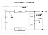
しかしながら、上述の従来の方式は、PN間の電圧箇所での地絡監視には有効であるがPN間電圧を外れた電圧箇所で地絡が発生すると誤った極性を表示してしまうという問題がある。たとえば、通常の地絡監視装置は、図10のように電池電圧をドロッパで調整して、ドロッパの入力電圧、たとえばDC120Vをドロッパで調整することによってDC110Vを得ている。このDC120Vの地点で地絡すると、従来方式では、RIN0=50kΩのとき、装置に流れ込む電流IEは2.6mAとなる。電圧VPEはー10Vであるので、表示抵抗値REはー3.8kΩとなる。
However, the above-described conventional method is effective for monitoring a ground fault at a voltage point between PNs, but has a problem that an erroneous polarity is displayed when a ground fault occurs at a voltage point outside the voltage between PNs. is there. For example, a normal ground fault monitoring apparatus obtains DC110V by adjusting the battery voltage with a dropper as shown in FIG. 10 and adjusting the dropper input voltage, for example, DC120V with the dropper. If a ground fault occurs at this point of
このため、P極側で地絡が発生しているにもかかわらずN極側で地絡しているという判定となってしまい、地絡箇所探索の妨げになる。 For this reason, it is determined that a ground fault has occurred on the N pole side even though a ground fault has occurred on the P pole side, which hinders the search for a ground fault location.
また、地絡の無い状態で地絡箇所電圧Vzを計算すると、測定ノイズや測定誤差の影響が大きくなり、このため計算結果のばらつきが大きくなるという問題がある。 In addition, when the ground fault location voltage Vz is calculated in the absence of a ground fault, there is a problem that the influence of measurement noise and measurement error is increased, and thus the variation in the calculation result is increased.
本発明は、上述のかかる事情に鑑みてなされたもので、PN間電圧を外れた電圧箇所でも正しく地絡箇所の極性表示を行うことができ、地絡箇所電圧の表示を精度良く行うことのできる直流回路の地絡監視装置および方法を提供することを目的とする。 The present invention has been made in view of the above-described circumstances, and can correctly display the polarity of a ground fault location even at a voltage location that deviates from the PN voltage, and accurately display the ground fault location voltage. An object of the present invention is to provide a DC circuit ground fault monitoring apparatus and method.
上記目的を達成するため、本発明に係わる直流回路の地絡監視装置は、中性点接地のアース電流Ieを測定する手段と、直流回路のP極とアースEとの間の電圧Vpeを測定する手段と、直流回路のアースEとN極との間の電圧Venを測定する手段と、前記測定した各電気データIe、Vpe、Venを用いて直流回路ドロッパの前後の地絡事故判定可能な情報を出力する地絡抵抗監視手段とを備え、特に、前記事故判定可能な情報は、地絡抵抗値と地絡位置識別情報とからなることを特徴とする。 In order to achieve the above object, the DC circuit ground fault monitoring apparatus according to the present invention measures the earth current Ie at the neutral point ground and the voltage Vpe between the P pole of the DC circuit and the ground E. , A means for measuring the voltage Ven between the ground E and the N pole of the DC circuit, and a ground fault before and after the DC circuit dropper can be determined using the measured electrical data Ie, Vpe, Ven. Ground fault resistance monitoring means for outputting information, and in particular, the information capable of determining an accident comprises a ground fault resistance value and ground fault position identification information.
これにより、PN間電圧をはずれた電圧箇所を含む広い範囲で直流回路の地絡を監視することができ、保守性が向上する。 As a result, the ground fault of the DC circuit can be monitored over a wide range including the voltage portion where the voltage between the PNs is off, and the maintainability is improved.
特に、前記地絡抵抗監視手段は、電流Ieが所定値以上であって、|Vpe/Ie|が所定値以下の条件のときに電圧Vpeが正ならば、Vpe/Ieの値を表示すると共にドロッパ後の地絡箇所識別表示を行い、当該条件のときに電圧Vpeが負ならば、|Vpe/Ie|の値を表示すると共にドロッパ前の地絡箇所識別表示を行うP極側監視手段と、電流Ieが所定値以下であって、|Ven/Ie|が所定値以下の条件のときに電圧Venが負ならば、Ven/Ieの値を表示すると共にドロッパ後の地絡箇所識別表示を行い、当該条件のときに電圧Venが正ならば、|Ven/Ie|の値を表示すると共にドロッパ前の地絡箇所識別表示を行うN極側監視手段とを有することを特徴とする。
これにより、直流回路のドロッパ前の地絡でも極性を正しく表示することが可能となる。
In particular, the ground fault resistance monitoring means displays the value of Vpe / Ie when the current Ie is equal to or greater than a predetermined value and the voltage Vpe is positive when | Vpe / Ie | P pole side monitoring means for performing ground fault location identification display after the dropper and displaying the value of | Vpe / Ie | and displaying the ground fault location identification display before the dropper if the voltage Vpe is negative under the above conditions If the current Ie is less than a predetermined value and the voltage Ven is negative when | Ven / Ie | is less than a predetermined value, the value of Ven / Ie is displayed and the ground fault location identification display after the dropper is displayed. If the voltage Ven is positive under the above conditions, there is provided an N pole side monitoring means for displaying the value of | Ven / Ie | and displaying the ground fault location identification display before the dropper.
This makes it possible to correctly display the polarity even with a ground fault before the dropper of the DC circuit.
好ましくは、P極ドロッパ前の地絡箇所識別表示は「♯」、P極ドロッパ後の地絡箇所識別表示は「+」、N極ドロッパ前の地絡箇所識別表示は「=」、N極ドロッパ後の地絡箇所識別表示は「−」にすると良い。 Preferably, the ground fault location identification display before the P pole dropper is “#”, the ground fault location identification display after the P pole dropper is “+”, the ground fault location identification display before the N pole dropper is “=”, and the N pole The ground fault location identification display after the dropper should be “−”.
「#」の符号は、「+」の符号を位置をずらして2度印刷した形をしており、P極の電圧よりも+の箇所で地絡していることを表示するのに適している。また、「=」の符号は「―」の符号を位置をずらして2度印刷した形をしており、N極の電圧よりもーの箇所で地絡していることを表示するのに適している。「#」「=」の文字を使うことにより、2度印刷の負担を軽減できる。また、作業員が感覚的に認識しやすく、認識ミスの削減を図ることができる。 The sign of “#” is printed twice with the position of the sign of “+”, and is suitable for displaying that a ground fault occurs at a location that is more positive than the voltage of the P pole. Yes. The sign of “=” is printed twice with the sign of “−” shifted, and it is suitable for displaying that there is a ground fault at a point more than the voltage of N pole. ing. By using the characters “#” and “=”, the burden of printing twice can be reduced. In addition, it is easy for a worker to perceive sensibly, and recognition errors can be reduced.
また、本発明に係わる直流回路の地絡監視装置は、直流回路のP極とアースEとの間の内部抵抗と、アースEとN極との間の内部抵抗を設定することによって分圧電圧を変える分圧電圧設定手段と、前記分圧電圧設定手段の設定による第1の分圧電圧に基づくPE間の電圧Vpe1、EN間の電圧Ven1、アース電流Ie1を読み込んだ後に、前記分圧電圧設定手段を切り替えて第2の分圧電圧に基づくPE間の電圧Vpe2、EN間の電圧Ven2、アース電流Ie2を読み込み、両設定のアース電流の差Ie1−Ie2の差が所定の範囲内にあるか否かを判定し、所定の範囲内にあるときは、地絡箇所電圧Vz=Ven1として、所定の範囲内に無いときは、近似式Vz=(Ie1*Ven2−Ie2*Ven1)/(Ie1−Ie2)に基づいて演算する地絡箇所電圧演算手段とを備えたことを特徴とする。 Further, the ground fault monitoring apparatus for a DC circuit according to the present invention sets the internal resistance between the P pole and the earth E of the DC circuit and the internal resistance between the earth E and the N pole, thereby dividing the divided voltage. The divided voltage setting means for changing the voltage, the voltage Vpe1 between PEs based on the first divided voltage set by the divided voltage setting means, the voltage Ven1 between EN, and the earth current Ie1, and then the divided voltage. The setting means is switched to read the voltage Vpe2 between PEs based on the second divided voltage, the voltage Ven2 between EN, and the earth current Ie2, and the difference between the two earth current differences Ie1 to Ie2 is within a predetermined range. If it is within the predetermined range, the ground fault location voltage Vz = Ven1, and if not within the predetermined range, the approximate expression Vz = (Ie1 * Ven2-Ie2 * Ven1) / (Ie1 -Ground fault location voltage calculation means to calculate based on -Ie2) It is characterized by that.
近似式によるVzの計算の前に、アース電流の差Ie1−Ie2の差が所定の範囲内にあるか否かを判定して、所定の範囲内にあるときは地絡箇所電圧をVen1として表示するため測定誤差の影響を受けず精度の高い地絡箇所電圧表示が可能となる。 Before calculating Vz by the approximate expression, it is determined whether or not the difference in ground current Ie1−Ie2 is within a predetermined range, and when it is within the predetermined range, the ground fault voltage is displayed as Ven1. Therefore, it is possible to display the ground fault voltage with high accuracy without being affected by the measurement error.
なお、前記地絡箇所電圧演算手段は、地絡抵抗監視手段が地絡発生判定を行ったときに起動し、前記地絡電圧表示と地絡抵抗値表示とを切り替える表示分圧電圧設定手段を備えるようにすれば、作業員は、地絡判定を迅速に行うことができる。 The ground fault location voltage calculation means is activated when the ground fault resistance monitoring means makes a ground fault occurrence determination, and displays divided voltage setting means for switching between the ground fault voltage display and the ground fault resistance value display. If it prepares, the worker can perform a ground fault determination rapidly.
また、本発明に係わる直流回路の地絡監視方法は、中性点接地のアース電流Ie、直流回路のP極とアースEとの間の電圧Vpe、直流回路のアースEとN極との間の電圧Venを測定し、前記電流Ieの絶対値が所定値以下のときは、地絡抵抗R64Dを無限大として表示し、前記電流Ieの絶対値が所定値以上のときは、次に電流値が所定値以上か以下かを判定し、前記電流Ieが所定値以上であって、|Vpe/Ie|が所定値以下の条件のときに電圧Vpeが正ならば、Vpe/Ieの値を表示すると共にドロッパ後の地絡箇所識別表示を行い、当該条件のときに電圧Vpeが負ならば、|Vpe/Ie|の値を表示すると共にドロッパ前の地絡箇所識別表示を行い、電流Ieが所定値以下であって、|Ven/Ie|が所定値以下の条件のときに電圧Venが負ならば、Ven/Ieの値を表示すると共にドロッパ後の地絡箇所識別表示を行い、当該条件のときに電圧Venが正ならば、|Ven/Ie|の値を表示すると共にドロッパ前の地絡箇所識別表示を行うことを特徴とする。 In addition, the ground fault monitoring method for a DC circuit according to the present invention includes the earth current Ie at the neutral point ground, the voltage Vpe between the P pole and the earth E of the DC circuit, and between the earth E and the N pole of the DC circuit. When the absolute value of the current Ie is less than or equal to a predetermined value, the ground fault resistance R64D is displayed as infinite. When the absolute value of the current Ie is greater than or equal to a predetermined value, the current value is If the current Ie is equal to or greater than a predetermined value and the voltage Vpe is positive when | Vpe / Ie | is equal to or smaller than the predetermined value, the value of Vpe / Ie is displayed. When the voltage Vpe is negative under the condition, the value of | Vpe / Ie | is displayed and the ground fault location identification display before the dropper is performed. If the voltage Ven is negative when it is less than the predetermined value and | Ven / Ie | is less than the predetermined value, Ven The value of Ie is displayed and the ground fault location identification display after the dropper is displayed. If the voltage Ven is positive under the condition, the value of | Ven / Ie | is displayed and the ground fault location identification display before the dropper is displayed. It is characterized by performing.
なお、電流Ieの絶対値が所定値以下という演算は、電流Ieが微小であることを判定するための演算であるため、実質的にこれと同じ内容の演算方法も含む。 Note that the calculation that the absolute value of the current Ie is equal to or less than the predetermined value is a calculation for determining that the current Ie is very small, and thus includes a calculation method having substantially the same contents.
このように、まず電流Ieについて判定を行うことによって、計算機の負荷を軽減することができる。 In this way, by first determining the current Ie, the load on the computer can be reduced.
さらに、本発明に係わる直流回路の地絡監視方法は、中性点接地のアース電流Ie、直流回路のP極とアースEとの間の電圧Vpe、直流回路のアースEとN極との間の電圧Venを測定して記憶部へ保存し、前記電流Ieの絶対値が所定値以上のときは、地絡箇所電圧演算手段を起動すると共に前記記憶部に保存されている各電気データを用いて地絡抵抗演算処理を行うことを特徴とする。 Further, the ground fault monitoring method for the DC circuit according to the present invention includes the earth current Ie at the neutral point ground, the voltage Vpe between the P pole and the earth E of the DC circuit, and between the earth E and the N pole of the DC circuit. When the absolute value of the current Ie is greater than or equal to a predetermined value, the ground fault location voltage calculation means is activated and each electrical data stored in the storage unit is used. And ground fault resistance calculation processing.
地絡箇所電圧演算は、内部抵抗の分圧を切り替えて電気データを測定するため、測定のために通常数分オーダの時間を要する。地絡抵抗演算処理において、収集した電気データのうち、電流Ieの値によって地絡電圧演算手段を起動してから記憶部に保存されている電気データを用いて地絡抵抗演算処理を行うようにすれば、地絡電圧演算結果を迅速に得ることができ、地絡事故等の復旧処理の効率が向上する。 The ground fault location voltage calculation requires electrical time on the order of several minutes for the measurement because the electrical data is measured by switching the partial voltage of the internal resistance. In the ground fault resistance calculation process, the ground fault resistance calculation process is performed using the electrical data stored in the storage unit after the ground fault voltage calculation means is activated by the value of the current Ie among the collected electrical data. If it does so, a ground fault voltage calculation result can be obtained quickly and the efficiency of recovery processing, such as a ground fault accident, improves.
以上の如く本発明によれば、PN間電圧を外れた電圧箇所でも正しく地絡箇所の極性表示を行うことができ、地絡が発生していないような場合でも地絡箇所電圧の表示を精度良く行うことが可能となる。 As described above, according to the present invention, the polarity of a ground fault location can be correctly displayed even at a voltage location that deviates from the PN voltage, and even when a ground fault does not occur, the display of the ground fault location voltage is accurate. It is possible to perform well.
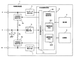
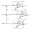
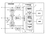
以下、本発明の第1の実施の形態を説明する。図1は、本実施の形態による直流回路の地絡監視装置のブロック図である。ここで、地絡監視装置1は、中性点接地のアース電流Ieを測定するIeデータ測定手段6、直流回路のP極とアースEとの間の電圧Vpeを測定するVpeデータ測定手段5、直流回路のアースEとN極との間の電圧Venを測定するVenデータ測定手段7、これら各測定手段5〜7の電気データを入力してデータ処理を行う中央演算処理部2、入力したデータや演算結果を記憶する記憶部3、演算結果を表示する表示部4、および、内部抵抗の設定制御を行う内部抵抗設定手段8a、8bから構成されている。測定手段5〜7は、図2に示すようにオペアンプ回路で構成することができる。
Hereinafter, a first embodiment of the present invention will be described. FIG. 1 is a block diagram of a ground fault monitoring apparatus for a DC circuit according to the present embodiment. Here, the ground
また、中央演算処理部2は、測定手段5〜7の電気データを入力し、また、内部抵抗設定手段8a、8bへ制御指令を出力する入出力処理手段21、測定した各電気データIe、Vpe、Venのデータを用いて地絡判定のための演算を行い、その演算結果を表示部4に対して出力する地絡抵抗監視手段22を備えている。この地絡抵抗監視手段22は、P極側監視手段221とN極側監視手段222を有している。
Further, the
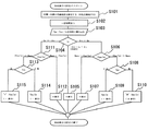
次に、上記の構成を有する地絡監視装置1の動作を図4のフローチャートを用いて説明する。
まず、地絡抵抗監視手段22は、一定周期、たとえば、一秒周期で起動され、P極とアースEの間(以下、PE間)およびアースEとN極の間(以下、EN間)の内部抵抗を設定する(S101)。
Next, operation | movement of the ground
First, the ground fault resistance monitoring means 22 is activated at a constant cycle, for example, one second cycle, between the P pole and the ground E (hereinafter referred to as “PE”) and between the ground E and the N pole (hereinafter referred to as “EN”). An internal resistance is set (S101).
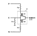
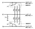
内部抵抗の設定は、内部抵抗設定手段8a、8bの切替スイッチによって、内部抵抗Rp、RnをそれぞれP極側、N極側と接続することによって実行されるが、図3に示すように、トランジスタQ1、Q2を地絡抵抗監視手段21からの制御指令により動作させることによって抵抗Rp、抵抗RnをそれぞれアースEと接続させるようにしても良い。これによって、電圧Vpeと、電圧Venが測定可能となる。
The internal resistance is set by connecting the internal resistances Rp and Rn to the P pole side and the N pole side by the changeover switches of the internal resistance setting means 8a and 8b, respectively. As shown in FIG. The resistors Rp and Rn may be connected to the ground E by operating Q1 and Q2 according to a control command from the ground fault
ここで、アース電流Ieは、図1に示すようにアースから装置内部へ流れ込む方向を正とする。また、電圧Vpeは、アースに対するP極の電圧であり、電圧Venは、N極に対するアースの電圧である。なお、抵抗Rpと抵抗Rnは、中性点接地となるように分圧比を定める。 Here, the ground current Ie is positive in the direction of flowing from the ground into the apparatus as shown in FIG. The voltage Vpe is a P-pole voltage with respect to the ground, and the voltage Ven is a ground voltage with respect to the N-pole. The resistance Rp and the resistance Rn determine the voltage division ratio so that the neutral point is grounded.
制御指令を出力してから一定時間後に電圧Vpe、電圧Ven、電流IeをAD変換器を介してデジタル信号として読み込んで記憶部3に保存する(S102、S103)。
The voltage Vpe, the voltage Ven, and the current Ie are read as digital signals via the AD converter and stored in the
その後、電流Ieの値がアース電流に関する所定値―δiから+δiの範囲内にあるか否かを判定して(S104)、この範囲内にある場合は表示部4に対して地絡抵抗R64Dが無限大「∞」(あるいは十分大きい)として表示出力を行う(S105)。 Thereafter, it is determined whether or not the value of the current Ie is within a range of a predetermined value −δi to + δi relating to the ground current (S104). If it is within this range, the ground fault resistance R64D is applied to the display unit 4. Display output is performed as infinite "∞" (or sufficiently large) (S105).
一方、電流Ieの値が所定値+δi以上のときは、P極側監視手段221によって、
|Vpe/Ie|を計算して、それが地絡抵抗に関する所定値RMAXよりも大きいか否かを判定する(S106)。そして、RMAXよりも大きい場合は、表示部4に対して地絡抵抗R64Dが無限大「∞」として表示出力を行う(S107)。一方、ステップS106において、|Vpe/Ie|がRMAX以下の場合は、次に電圧Vpeの正負を判定し(S108)、電圧Vpeが0または正のときは、地絡抵抗R64Dとして「+」表示と共にVpe/Ieの値を表示する(S109)。ステップS108で電圧Vpeが負のときは、地絡抵抗R64Dとして「♯」表示と共に|Vpe/Ie|の値を表示する(S110)。
On the other hand, when the value of the current Ie is equal to or greater than the predetermined value + δi, the P pole
It is determined whether or not | Vpe / Ie | is larger than a predetermined value RMAX related to the ground fault resistance (S106). If it is greater than RMAX, the ground fault resistance R64D is output to the display unit 4 as infinite "∞" (S107). On the other hand, if | Vpe / Ie | is less than or equal to RMAX in step S106, then the positive or negative of the voltage Vpe is determined (S108). If the voltage Vpe is 0 or positive, “+” is displayed as the ground fault resistance R64D. At the same time, the value of Vpe / Ie is displayed (S109). When the voltage Vpe is negative in step S108, the value of | Vpe / Ie | is displayed together with “#” as the ground fault resistance R64D (S110).
この「+」表示は、P極のドロッパの後方(通過後)の位置で地絡の可能性があることを示すものである。また、「♯」表示は、P極のドロッパの通過前、即ち、整流器側で地絡の可能性があることを示すものである。 This “+” display indicates that there is a possibility of a ground fault at a position behind (after passing) the P-pole dropper. The “#” indication indicates that there is a possibility of a ground fault before passing through the P-pole dropper, that is, on the rectifier side.
以上のように、Vpe/IeまたはVen/Ienの極性で地絡箇所がP極側かN極側かの判定を行うと直流回路のドロッパ通過前(ドロッパの整流器側)で地絡事故が起きた場合は、間違った判定となり事故調査に支障を来たすことになるが本実施の形態では、VpeまたはVenの値に基づいてP極側、N極側の地絡箇所の判定を正確に行うことが可能となる。 As described above, when the polarity of Vpe / Ie or Ven / Ien is used to determine whether the ground fault location is the P pole side or the N pole side, a ground fault occurs before the DC circuit passes through the dropper (dropper rectifier side). In this case, the determination is wrong, which causes trouble in the accident investigation. In the present embodiment, the determination of the ground fault location on the P pole side and the N pole side should be made accurately based on the value of Vpe or Ven. Is possible.
特に電流Ieを常時監視し、その値が所定値を超えたかどうかでP極側監視手段221またはN極側監視手段222を起動するようにしたので、地絡監視処理の負荷を軽減することができる。
In particular, the current Ie is constantly monitored, and the P-pole
次に、第2の実施の形態を説明する。図5は本実施の形態による地絡監視装置1のブロック図である。図1との違いは、中央演算処理部2の機能として、地絡箇所電圧演算手段25と、地絡抵抗と地絡箇所電圧の表示を切り替える表示切替手段26を備えたことである。また、図3の内部抵抗設定手段は、図6のように複数の抵抗を切り替えて設定可能になっている。
Next, a second embodiment will be described. FIG. 5 is a block diagram of the ground
地絡箇所電圧Vzの計算式として、以下の近似式情報が記憶部3に保存されている。
Vz=(Ie1*Ven2−Ie2*Ven1)/(Ie1−Ie2) ・・・ (1)
The following approximate expression information is stored in the
Vz = (Ie1 * Ven2-Ie2 * Ven1) / (Ie1-Ie2) (1)
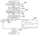
次に地絡箇所電圧演算手段25の動作を図7のフローチャートを用いて説明する。
地絡箇所電圧演算手段25は、装置1に設けられた測定開始ボタン(RPNボタン)を押すことによって起動される。
Next, the operation of the ground fault location voltage calculation means 25 will be described using the flowchart of FIG.
The ground fault location voltage calculation means 25 is activated by pressing a measurement start button (RPN button) provided in the
地絡箇所電圧演算手段25は起動されると、まず、PE間、EN間の内部抵抗を設定する(S201)。具体的には、内部抵抗設定手段8a、8bに切替指令を出力して、中性点接地となる抵抗の組合せである抵抗R1p、R1nを選択する。そして、対地静電容量およびAD変換器の動作時間を考慮した一定時間後に(S202)、Vpe1、Ven1、Ie1を同時に読み込んで記憶部3に保存する(S203)。 When the ground fault location voltage calculation means 25 is activated, first, an internal resistance between PEs and between ENs is set (S201). Specifically, a switching command is output to the internal resistance setting means 8a and 8b, and the resistances R1p and R1n, which are combinations of resistances for neutral grounding, are selected. Then, after a predetermined time considering the ground capacitance and the operation time of the AD converter (S202), Vpe1, Ven1, and Ie1 are simultaneously read and stored in the storage unit 3 (S203).
次に、PE間、EN間の内部抵抗を切り替えて分圧電圧を変える(S204)。このとき、地絡抵抗監視手段22の地絡判定結果に基づいて分圧比を変えるようにするとよい。すなわち、P極地絡ならば、P極側抵抗値を相対的に小さく、N極側抵抗値を相対的に大きくする方向で分圧比を変える。逆に、N極地絡ならば、P極側抵抗値を相対的に大きく、N極側抵抗値を相対的に大きくする方向で分圧比を変える。図6において、P極地絡の場合は、抵抗R2pと抵抗R2n(R2p<R2n)を選択し、N極地絡の場合は、抵抗R3pと抵抗R3n(R3p>R3n)を選択するようにする。このように地絡発生方向へ分圧電圧を振らすことによって機器へのダメージを少なくすることができる。
そして、一定時間後に分圧電圧を変更して測定した電気データVpe2、Ven2、Ie2を同時に読み込む(S205、S206)。
Next, the divided voltage is changed by switching the internal resistance between PE and EN (S204). At this time, the voltage division ratio may be changed based on the ground fault determination result of the ground fault
Then, electrical data Vpe2, Ven2, and Ie2 measured by changing the divided voltage after a certain time are read simultaneously (S205, S206).
その後、(1)式の分母が所定値の範囲内にあるか否かを判定して(S207)、所定値の範囲内にある場合は、Vz=Ven1として(S208)、Vzの値を表示する(S210)。一方、ステップS207で所定値の範囲にない場合は、上記(1)式に基づいて地絡箇所電圧Vzを演算して(S209)、この結果を表示する(S210)。 Thereafter, it is determined whether or not the denominator of the expression (1) is within a predetermined value range (S207). If it is within the predetermined value range, Vz = Ven1 is set (S208) and the value of Vz is displayed. (S210). On the other hand, if it is not in the predetermined value range in step S207, the ground fault location voltage Vz is calculated based on the above equation (1) (S209), and the result is displayed (S210).
なお、ステップS110で演算結果を表示する場合は、表示分圧電圧設定手段26に切替指令を出力して地絡抵抗値表示から地絡箇所電圧表示へ切り替えるようにする。 In addition, when displaying a calculation result by step S110, a switching command is output to the display partial voltage setting means 26, and it switches from a ground fault resistance value display to a ground fault location voltage display.
本実施の形態によれば、地絡箇所電圧Vzの算出で使用される2つのアース電流の差が小さいときは、Vz値として電圧Ven1の値を用いることとしたので、不安定な表示を防止することができる。特に、外来ノイズ進入を防止することによって不安定な表示を回避することもできるが、本実施の形態によれば、そのようなノイズ対策は必要なくなり、ノイズの大きな環境でも精度よく、迅速な演算が可能となる。 According to the present embodiment, when the difference between the two ground currents used in the calculation of the ground fault location voltage Vz is small, the voltage Ven1 is used as the Vz value, thereby preventing unstable display. can do. In particular, unstable display can be avoided by preventing the entry of external noise, but according to the present embodiment, such noise countermeasures are no longer necessary, and accurate and quick computation can be performed even in noisy environments. Is possible.
なお、地絡箇所電圧演算手段25は、地絡抵抗監視手段22の処理で抵抗が無限大以外の判定になったときに起動するようにしても良い。地絡箇所電圧の測定は抵抗を切り替えて演算するため、対地静電容量により測定表示に数分の時間がかかる。抵抗が無限大以外の判定、即ち、地絡事故の可能性ありの判定になったときに起動するようにしてその結果を保存しておけば作業員は直ちに地絡箇所電圧情報を取得することが可能となる。 The ground fault location voltage calculation means 25 may be activated when the resistance of the ground fault resistance monitoring means 22 is determined to be other than infinity. Since the earth fault location voltage is calculated by switching the resistance, the measurement display takes several minutes due to the ground capacitance. If it is determined that the resistance is not infinite, that is, it is determined that there is a possibility of a ground fault, if the result is stored and the result is saved, the worker should immediately acquire the ground fault voltage information. Is possible.
以下、地絡箇所電圧を効率的に取得するための実施例を説明する。
図8は、本実施例に係わる地絡抵抗監視手段22のフローチャートである。
ここで、ステップS101からステップS103の処理は、図4と同様であるが、中性点接地として、抵抗R1p、R1nを選択して、そのときの電気データVpe1、Ven1、Ie1を読み込んで記憶部3に保存する。
Hereinafter, an embodiment for efficiently acquiring the ground fault location voltage will be described.
FIG. 8 is a flowchart of the ground fault
Here, the processing from step S101 to step S103 is the same as that in FIG. 4, but the resistors R1p and R1n are selected as the neutral point grounding, and the electrical data Vpe1, Ven1, and Ie1 at that time are read and stored. Save to 3.
そして、ステップS104において、アース電流Ieが所定値δi以上のときは、P極側地絡発生可能性ありとして、内部抵抗をR2p、R2nに設定して(S116)、地絡箇所電圧演算手段25を起動した後に(S117)、ステップS106以降を実行する。
また、ステップS104において、アース電流Ieが所定値―δi以下のときは、N極側地絡発生可能性ありとして、内部抵抗をR3p、R3nに設定して(S118)、地絡箇所電圧演算手段25を起動した後に(S119)、ステップS111以降を実行する。
そして、ステップS106あるいはステップS111以降の処理では、記憶部3に保存されている電気データVpe1、Ven1、Ie1を用いて処理を実行する。その他、各ステップの処理は図4の対応するステップの処理と同様である。
In step S104, when the ground current Ie is equal to or greater than the predetermined value δi, the P-pole side ground fault is likely to occur, the internal resistance is set to R2p, R2n (S116), and the ground fault location voltage calculation means 25 is set. (S117), step S106 and subsequent steps are executed.
In step S104, if the ground current Ie is less than or equal to the predetermined value -δi, the N-side ground fault may occur, the internal resistance is set to R3p, R3n (S118), and the ground fault location voltage calculation means 25 is started (S119), step S111 and subsequent steps are executed.
In the processing after step S106 or step S111, the processing is executed using the electrical data Vpe1, Ven1, and Ie1 stored in the
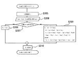
次に、図9を用いて、本実施例による地絡箇所電圧表示手段25の動作を説明する。この図の各ステップ番号は、図7のステップ番号に対応している。図9において、地絡箇所電圧表示手段25は起動されると、まず、対地静電容量およびAD変換器の動作時間を考慮した一定時間後に(S205)、電気データVpe2、Ven2、Ie2を読み込む(S206)。この電気データは、地絡抵抗監視手段22によって分圧電圧が変更された状態の電気データである。
Next, the operation of the ground fault location voltage display means 25 according to this embodiment will be described with reference to FIG. Each step number in this figure corresponds to the step number in FIG. In FIG. 9, when the ground fault location voltage display means 25 is activated, first, electrical data Vpe2, Ven2, and Ie2 are read after a predetermined time considering the capacitance to ground and the operation time of the AD converter (S205) ( S206). This electrical data is electrical data in a state where the divided voltage is changed by the ground fault
そして、これらの伝記データと記憶部3に保存されている中性点接地での電気データVpe1、Ven1、Ie1を用いてステップS207以降の処理を実行する。
And the process after step S207 is performed using these biographed data and the electrical data Vpe1, Ven1, and Ie1 at neutral point grounding preserve | saved at the memory |
本実施例によれば、中性点接地での電気データを記憶部に保存しつつ、地絡抵抗監視手段22によって、地絡抵抗の演算を行い、地絡発生可能性ありの判定となったときに、地絡箇所電圧演算手段25を起動すると共に地絡抵抗監視手段22は、記憶部のデータを用いながら地絡抵抗演算を継続する。また、地絡箇所電圧演算手段25は、一定時間後に分圧電圧の変更された状態での電気データを読み込むと共に記憶部3に保存されている中性点接地での電気データを用いて地絡箇所電圧の演算を行うので、地絡抵抗の監視に支障を来たすことなく地絡発生時の地絡箇所電圧データを早く取得することができ、地絡事故等における調査復旧作業を迅速に行うことが可能となる。
According to the present embodiment, the ground fault resistance is calculated by the ground fault
1 地絡監視装置
2 中央演算処理部
3 記憶部
4 表示部
5 Vpeデータ測定手段
6 Ieデータ測定手段
7 Venデータ測定手段
8、8a、8b 内部抵抗設定手段
22 地絡抵抗監視手段
25 地絡箇所電圧演算手段
26 表示切替手段
221 P極側監視手段
222 N極側監視手段
DESCRIPTION OF
Claims (8)
直流回路のP極とアースEとの間の電圧Vpeを測定する手段と、
直流回路のアースEとN極との間の電圧Venを測定する手段と、
前記測定した各電気データIe、Vpe、Venを用いて直流回路ドロッパの前後の地絡事故判定可能な情報を出力する地絡抵抗監視手段と、
を備えたことを特徴とする直流回路の地絡監視装置。 Means for measuring the earth current Ie at the neutral point ground;
Means for measuring the voltage Vpe between the P-pole of the DC circuit and the ground E;
Means for measuring the voltage Ven between the ground E and the N pole of the DC circuit;
A ground fault resistance monitoring means for outputting information capable of determining a ground fault before and after the DC circuit dropper using the measured electrical data Ie, Vpe, and Ven;
A ground fault monitoring device for a DC circuit, comprising:
電流Ieが所定値以下であって、|Ven/Ie|が所定値以下の条件のときに電圧Venが負ならば、Ven/Ieの値を表示すると共にドロッパ後の地絡箇所識別表示を行い、当該条件のときに電圧Venが正ならば、|Ven/Ie|の値を表示すると共にドロッパ前の地絡箇所識別表示を行うN極側監視手段と、
を有することを特徴とする請求項2記載の直流回路の地絡監視装置。 The ground fault resistance monitoring means displays the value of Vpe / Ie and displays the value of Vpe / Ie when the current Ie is equal to or greater than a predetermined value and the voltage Vpe is positive when | Vpe / Ie | And P pole side monitoring means for displaying the value of | Vpe / Ie | and displaying the ground fault location identification display before the dropper if the voltage Vpe is negative under the above conditions.
If the current Ie is less than or equal to a predetermined value and the voltage Ven is negative when | Ven / Ie | is less than or equal to a predetermined value, the Ven / Ie value is displayed and the ground fault location identification display after the dropper is performed. If the voltage Ven is positive under the above conditions, the N pole side monitoring means for displaying the value of | Ven / Ie | and displaying the ground fault location in front of the dropper,
The ground fault monitoring apparatus for a DC circuit according to claim 2, comprising:
前記分圧電圧設定手段の設定による第1の分圧電圧に基づくPE間の電圧Vpe1、EN間の電圧Ven1、アース電流Ie1を読み込んだ後に、前記分圧電圧設定手段の設定を切り替えて第2の分圧電圧に基づくPE間の電圧Vpe2、EN間の電圧Ven2、アース電流Ie2を読み込み、両設定のアース電流の差Ie1−Ie2の差が所定の範囲内にあるか否かを判定し、所定の範囲内にあるときは、地絡箇所電圧Vz=Ven1として、所定の範囲内に無いときは、近似式Vz=(Ie1*Ven2−Ie2*Ven1)/(Ie1−Ie2)に基づいて演算する地絡箇所電圧演算手段と、
を備えたことを特徴とする直流回路の地絡監視装置。 A divided voltage setting means for setting a divided voltage by connecting an internal resistance between the P pole of the DC circuit and the earth E and an internal resistance between the earth E and the N pole,
After reading the voltage Vpe1 between PEs, the voltage Ven1 between PEs, and the ground current Ie1 based on the first divided voltage set by the divided voltage setting means, the setting of the divided voltage setting means is switched to the second. The voltage Vpe2 between PEs, the voltage Ven2 between EN, and the earth current Ie2 are read based on the divided voltages of the two, and it is determined whether or not the difference between the two earth current differences Ie1−Ie2 is within a predetermined range. When it is within the predetermined range, the ground fault voltage Vz = Ven1, and when it is not within the predetermined range, the calculation is based on the approximate expression Vz = (Ie1 * Ven2-Ie2 * Ven1) / (Ie1-Ie2). A ground fault location voltage calculating means,
A ground fault monitoring device for a DC circuit, comprising:
前記電流Ieの絶対値が所定値以下のときは、地絡抵抗R64Dを無限大として表示し、
前記電流Ieの絶対値が所定値以上のときは、次に電流値が所定値以上か以下かを判定し、
前記電流Ieが所定値以上であって、|Vpe/Ie|が所定値以下の条件のときに電圧Vpeが正ならば、Vpe/Ieの値を表示すると共にドロッパ後の地絡箇所識別表示を行い、当該条件のときに電圧Vpeが負ならば、|Vpe/Ie|の値を表示すると共にドロッパ前の地絡箇所識別表示を行い、
電流Ieが所定値以下であって、|Ven/Ie|が所定値以下の条件のときに電圧Venが負ならば、Ven/Ieの値を表示すると共にドロッパ後の地絡箇所識別表示を行い、当該条件のときに電圧Venが正ならば、|Ven/Ie|の値を表示すると共にドロッパ前の地絡箇所識別表示を行うことを特徴とする直流回路の地絡監視方法。 Measure the earth current Ie at the neutral point ground, the voltage Vpe between the P pole and the earth E of the DC circuit, and the voltage Ven between the earth E and the N pole of the DC circuit,
When the absolute value of the current Ie is below a predetermined value, the ground fault resistance R64D is displayed as infinite,
When the absolute value of the current Ie is greater than or equal to a predetermined value, it is then determined whether the current value is greater than or equal to a predetermined value;
If the current Ie is greater than or equal to a predetermined value and the voltage Vpe is positive when | Vpe / Ie | is less than or equal to a predetermined value, the value of Vpe / Ie is displayed and a ground fault location identification display after the dropper is displayed. If the voltage Vpe is negative under the conditions, the value of | Vpe / Ie | is displayed and the ground fault location identification display before the dropper is performed.
If the current Ie is less than or equal to a predetermined value and the voltage Ven is negative when | Ven / Ie | is less than or equal to a predetermined value, the Ven / Ie value is displayed and the ground fault location identification display after the dropper is performed. If the voltage Ven is positive under the above conditions, the value of | Ven / Ie | is displayed and the ground fault location identification display before the dropper is displayed.
前記電流Ieの絶対値が所定値以上のときは、地絡箇所電圧演算手段を起動すると共に前記記憶部に保存されている各電気データを用いて地絡抵抗演算処理を行うことを特徴とする直流回路の地絡監視方法。
The earth current Ie at the neutral point ground, the voltage Vpe between the P pole and the earth E of the DC circuit, and the voltage Ven between the earth E and the N pole of the DC circuit are measured and stored in the storage unit.
When the absolute value of the current Ie is equal to or greater than a predetermined value, the ground fault location voltage calculation means is activated and a ground fault resistance calculation process is performed using each electrical data stored in the storage unit. DC circuit ground fault monitoring method.
Priority Applications (1)
| Application Number | Priority Date | Filing Date | Title |
|---|---|---|---|
| JP2004107758A JP4456402B2 (en) | 2004-03-31 | 2004-03-31 | DC circuit ground fault monitoring device |
Applications Claiming Priority (1)
| Application Number | Priority Date | Filing Date | Title |
|---|---|---|---|
| JP2004107758A JP4456402B2 (en) | 2004-03-31 | 2004-03-31 | DC circuit ground fault monitoring device |
Publications (2)
| Publication Number | Publication Date |
|---|---|
| JP2005291930A true JP2005291930A (en) | 2005-10-20 |
| JP4456402B2 JP4456402B2 (en) | 2010-04-28 |
Family
ID=35325017
Family Applications (1)
| Application Number | Title | Priority Date | Filing Date |
|---|---|---|---|
| JP2004107758A Expired - Fee Related JP4456402B2 (en) | 2004-03-31 | 2004-03-31 | DC circuit ground fault monitoring device |
Country Status (1)
| Country | Link |
|---|---|
| JP (1) | JP4456402B2 (en) |
Cited By (5)
| Publication number | Priority date | Publication date | Assignee | Title |
|---|---|---|---|---|
| CN101452632B (en) * | 2007-11-29 | 2010-12-15 | 上海蓝瑞软件技术有限公司 | Single-phase earth fault diagnostic equipment |
| DE102011076557A1 (en) | 2010-05-27 | 2011-12-01 | Denso Corporation | VEHICLE ENGINE CONTROL UNIT |
| JP2012119382A (en) * | 2010-11-29 | 2012-06-21 | Jx Nippon Oil & Energy Corp | Ground fault detection device, ground fault detection method, photovoltaic power generation system, and ground fault detection program |
| JP2012251867A (en) * | 2011-06-02 | 2012-12-20 | Chugoku Electric Power Co Inc:The | Ground fault detection device and program |
| CN105589004A (en) * | 2014-10-13 | 2016-05-18 | 国家电网公司 | Method and device for judging substation relay protection-used PT secondary common circuit single-point grounding |
-
2004
- 2004-03-31 JP JP2004107758A patent/JP4456402B2/en not_active Expired - Fee Related
Cited By (5)
| Publication number | Priority date | Publication date | Assignee | Title |
|---|---|---|---|---|
| CN101452632B (en) * | 2007-11-29 | 2010-12-15 | 上海蓝瑞软件技术有限公司 | Single-phase earth fault diagnostic equipment |
| DE102011076557A1 (en) | 2010-05-27 | 2011-12-01 | Denso Corporation | VEHICLE ENGINE CONTROL UNIT |
| JP2012119382A (en) * | 2010-11-29 | 2012-06-21 | Jx Nippon Oil & Energy Corp | Ground fault detection device, ground fault detection method, photovoltaic power generation system, and ground fault detection program |
| JP2012251867A (en) * | 2011-06-02 | 2012-12-20 | Chugoku Electric Power Co Inc:The | Ground fault detection device and program |
| CN105589004A (en) * | 2014-10-13 | 2016-05-18 | 国家电网公司 | Method and device for judging substation relay protection-used PT secondary common circuit single-point grounding |
Also Published As
| Publication number | Publication date |
|---|---|
| JP4456402B2 (en) | 2010-04-28 |
Similar Documents
| Publication | Publication Date | Title |
|---|---|---|
| CN104767464B (en) | The insulation resistance detection method of motor drive and motor | |
| EP2933646B1 (en) | Precision measurement of voltage drop across a semiconductor switching element | |
| EP2345905B1 (en) | Battery characteristic evaluator | |
| CN102162834A (en) | Battery voltage detecting device in serially-connected battery pack and method of battery voltage detecting device | |
| EP1922554B1 (en) | Current measurement circuit and method of diagnosing faults in same | |
| CN113865757B (en) | Detection circuit, detection method and electronic equipment of piezoresistive pressure sensor | |
| EP3470860A1 (en) | Voltage detection and determination circuit and power battery system having same | |
| JP4456402B2 (en) | DC circuit ground fault monitoring device | |
| EP3301437B1 (en) | Measurement circuitry for evaluating a resistance of a resistive gas sensor | |
| US10535990B2 (en) | Power supply device, detection circuit and power supply method thereof | |
| US20200112169A1 (en) | System and method for over voltage protection in both positive and negative polarities | |
| CN109709380B (en) | Method and device for detecting operating characteristics of accelerator | |
| CN114236226B (en) | A voltage measuring circuit | |
| JPH11133093A (en) | Device, for measuring ground fault resistance, etc., in dc electric path | |
| JP4777828B2 (en) | Measuring device and inspection device | |
| JP4208560B2 (en) | Impedance measuring device | |
| JP4865516B2 (en) | measuring device | |
| CN105940312A (en) | The method of calculating the power supply voltage of the load and the load | |
| JP2006177765A (en) | Earthester and ground resistance measurement method | |
| JP2018189534A (en) | Wire inspection device | |
| CN114167140B (en) | Method and system for detecting insulation-to-ground resistance of DC systems | |
| JP5012430B2 (en) | DC test equipment and semiconductor test equipment | |
| US12360010B2 (en) | Method for diagnosing a wideband lambda sensor | |
| CN117269804B (en) | Device and method for detecting resistance of battery module of electric energy storage system | |
| JPH11281688A (en) | Constant current source and resistance measuring device |
Legal Events
| Date | Code | Title | Description |
|---|---|---|---|
| A621 | Written request for application examination |
Free format text: JAPANESE INTERMEDIATE CODE: A621 Effective date: 20070314 |
|
| A977 | Report on retrieval |
Free format text: JAPANESE INTERMEDIATE CODE: A971007 Effective date: 20090717 |
|
| A131 | Notification of reasons for refusal |
Free format text: JAPANESE INTERMEDIATE CODE: A131 Effective date: 20090728 |
|
| A521 | Request for written amendment filed |
Free format text: JAPANESE INTERMEDIATE CODE: A523 Effective date: 20090928 |
|
| TRDD | Decision of grant or rejection written | ||
| A01 | Written decision to grant a patent or to grant a registration (utility model) |
Free format text: JAPANESE INTERMEDIATE CODE: A01 Effective date: 20100112 |
|
| A01 | Written decision to grant a patent or to grant a registration (utility model) |
Free format text: JAPANESE INTERMEDIATE CODE: A01 |
|
| A61 | First payment of annual fees (during grant procedure) |
Free format text: JAPANESE INTERMEDIATE CODE: A61 Effective date: 20100205 |
|
| FPAY | Renewal fee payment (event date is renewal date of database) |
Free format text: PAYMENT UNTIL: 20130212 Year of fee payment: 3 |
|
| R150 | Certificate of patent or registration of utility model |
Ref document number: 4456402 Country of ref document: JP Free format text: JAPANESE INTERMEDIATE CODE: R150 Free format text: JAPANESE INTERMEDIATE CODE: R150 |
|
| FPAY | Renewal fee payment (event date is renewal date of database) |
Free format text: PAYMENT UNTIL: 20140212 Year of fee payment: 4 |
|
| R250 | Receipt of annual fees |
Free format text: JAPANESE INTERMEDIATE CODE: R250 |
|
| R250 | Receipt of annual fees |
Free format text: JAPANESE INTERMEDIATE CODE: R250 |
|
| R250 | Receipt of annual fees |
Free format text: JAPANESE INTERMEDIATE CODE: R250 |
|
| R250 | Receipt of annual fees |
Free format text: JAPANESE INTERMEDIATE CODE: R250 |
|
| R250 | Receipt of annual fees |
Free format text: JAPANESE INTERMEDIATE CODE: R250 |
|
| R250 | Receipt of annual fees |
Free format text: JAPANESE INTERMEDIATE CODE: R250 |
|
| R250 | Receipt of annual fees |
Free format text: JAPANESE INTERMEDIATE CODE: R250 |
|
| R250 | Receipt of annual fees |
Free format text: JAPANESE INTERMEDIATE CODE: R250 |
|
| R250 | Receipt of annual fees |
Free format text: JAPANESE INTERMEDIATE CODE: R250 |
|
| R250 | Receipt of annual fees |
Free format text: JAPANESE INTERMEDIATE CODE: R250 |
|
| R250 | Receipt of annual fees |
Free format text: JAPANESE INTERMEDIATE CODE: R250 |
|
| LAPS | Cancellation because of no payment of annual fees |