JP2005291666A - Combustion apparatus - Google Patents
Combustion apparatus Download PDFInfo
- Publication number
- JP2005291666A JP2005291666A JP2004110715A JP2004110715A JP2005291666A JP 2005291666 A JP2005291666 A JP 2005291666A JP 2004110715 A JP2004110715 A JP 2004110715A JP 2004110715 A JP2004110715 A JP 2004110715A JP 2005291666 A JP2005291666 A JP 2005291666A
- Authority
- JP
- Japan
- Prior art keywords
- combustion
- burner
- burner body
- gas
- guide cylinder
- Prior art date
- Legal status (The legal status is an assumption and is not a legal conclusion. Google has not performed a legal analysis and makes no representation as to the accuracy of the status listed.)
- Pending
Links
- 238000002485 combustion reaction Methods 0.000 title claims abstract description 68
- 230000002093 peripheral effect Effects 0.000 claims abstract description 26
- 239000007789 gas Substances 0.000 claims description 50
- 239000000567 combustion gas Substances 0.000 claims description 32
- 230000000149 penetrating effect Effects 0.000 claims description 5
- 230000015572 biosynthetic process Effects 0.000 claims 1
- 230000000694 effects Effects 0.000 description 11
- 238000005192 partition Methods 0.000 description 6
- 239000002737 fuel gas Substances 0.000 description 2
- 239000011810 insulating material Substances 0.000 description 2
- UGFAIRIUMAVXCW-UHFFFAOYSA-N Carbon monoxide Chemical compound [O+]#[C-] UGFAIRIUMAVXCW-UHFFFAOYSA-N 0.000 description 1
- 206010067482 No adverse event Diseases 0.000 description 1
- 230000002411 adverse Effects 0.000 description 1
- 229910002091 carbon monoxide Inorganic materials 0.000 description 1
- 230000002950 deficient Effects 0.000 description 1
- 239000000446 fuel Substances 0.000 description 1
- 239000011491 glass wool Substances 0.000 description 1
- 239000002241 glass-ceramic Substances 0.000 description 1
- 238000010438 heat treatment Methods 0.000 description 1
- 229910052751 metal Inorganic materials 0.000 description 1
- 239000002184 metal Substances 0.000 description 1
- 239000007769 metal material Substances 0.000 description 1
- 230000004048 modification Effects 0.000 description 1
- 238000012986 modification Methods 0.000 description 1
- 230000000630 rising effect Effects 0.000 description 1
- 230000001502 supplementing effect Effects 0.000 description 1
- 238000011144 upstream manufacturing Methods 0.000 description 1
Images
Landscapes
- Gas Burners (AREA)
Abstract
Description
本発明は、燃焼機器、特に、ガスバーナを具備する燃焼機器に関する。 The present invention relates to a combustion device, and more particularly to a combustion device equipped with a gas burner.
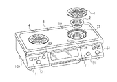
燃焼機器として、図6に示すように、天板(1)に円形のバーナ用開口(10)が形成され、前記開口(10)の下方に、燃焼室(20)が設けられ、前記燃焼室(20)から吐出された燃焼排気で鍋(44)を加熱する形式のガスコンロがある。
前記燃焼室(20)内には、ガスバーナ(3)の炎孔(35)(35)が開設されたバーナボディ(30)が収容されていると共に、その底壁(21)には、二次空気供給用孔(22)が開設されている。又、前記開口(10)は、五徳兼用カバー(4)で覆われている。
前記五徳兼用カバー(4)は、上面に、放射状に延びる複数の鍋載置リブ(40)が隆起していると共に、前記鍋載置リブ(40)には、前記燃焼室(20)に連通する排気口(41)が開設されている。
この従来のガスコンロでは、前記燃焼室(20)から吐出された燃焼排気が、五徳兼用カバー(4)の排気口(41)から吐出され、前記五徳兼用カバー(4)の鍋載置リブ(40)上に載置させた鍋(44)の底が加熱される構成となっている。
この従来のものでは、天板(1)に設けたバーナ用開口(10)を、五徳兼用カバー(4)で覆うことにより、ガスコンロの上面のデザインをすっきりさせることができ、意匠感が向上する。
The combustion chamber (20) accommodates a burner body (30) in which a flame hole (35) (35) of a gas burner (3) is opened, and the bottom wall (21) has a secondary wall. An air supply hole (22) is opened. The opening (10) is covered with a virtuosity cover (4).
The five-purpose cover (4) has a plurality of pan mounting ribs (40) extending radially on its upper surface, and the pan mounting rib (40) communicates with the combustion chamber (20). An exhaust port (41) is opened.
In this conventional gas stove, the combustion exhaust discharged from the combustion chamber (20) is discharged from the exhaust port (41) of the virtually combined cover (4), and the pan mounting rib (40 ) The bottom of the pan (44) placed on the top is heated.
In this conventional one, by covering the burner opening (10) provided on the top plate (1) with the virtually combined cover (4), the design of the upper surface of the gas stove can be cleaned, and the design feeling is improved. .
上記従来のものでは、天板(1)の上方から、ガスバーナ(3)の燃焼用の二次空気を取り入れることができないので、二次空気は、専らガスコンロの底壁(21)に設けた空気供給用孔(22)からの供給に頼ることとなる。しかしながら、空気供給用孔(22)から取り入れられる二次空気は、燃焼室(20)内に拡散してしまい、バーナボディ(30)の炎孔(35)に効率良く供給することができない。よって、前記炎孔(35)に供給される二次空気は不足気味となる。
燃焼用二次空気が不足すると、炎孔(35)から噴き出される燃焼炎の長さが長くなって、前記五徳兼用カバー(4)に接触することにより、燃焼炎が冷却され、これにより、一酸化炭素が生じ易くなるという不都合が生じる。
本発明は、かかる点に鑑みてなされたものであり、『ガスバーナを備えた燃焼機器』において、燃焼時に必要十分な量の燃焼用二次空気を供給できるようにすることを課題とする。
In the above conventional one, since the secondary air for combustion of the gas burner (3) cannot be taken from above the top plate (1), the secondary air is the air provided exclusively on the bottom wall (21) of the gas stove. It depends on the supply from the supply hole (22). However, the secondary air taken in from the air supply hole (22) diffuses into the combustion chamber (20) and cannot be efficiently supplied to the flame hole (35) of the burner body (30). Therefore, the secondary air supplied to the flame hole (35) becomes deficient.
When the secondary air for combustion is insufficient, the length of the combustion flame ejected from the flame hole (35) is increased, and the combustion flame is cooled by coming into contact with the virtually combined cover (4). There arises a disadvantage that carbon monoxide is easily generated.
The present invention has been made in view of this point, and an object of the present invention is to be able to supply a necessary and sufficient amount of secondary air for combustion during combustion in a “combustion device equipped with a gas burner”.
[請求項1に係る発明]
上記課題を解決する為の請求項1に係る発明の技術的手段は、
『前記ガスバーナは、環状に構成されたバーナボディを具備し、
前記バーナボディの内側周面で包囲された内側空間内にそれよりも小径のガイド筒が収容され、
前記バーナボディの前記内側周面に複数の炎孔が開設されると共に、前記炎孔に対応する前記ガイド筒の各位置に窓部が開設され、
前記バーナボディの上方又は下方から前記バーナボディと前記ガイド筒との隙間に連通する二次空気供給通路が設けられている』ことである。
上記技術的手段は次のように作用する。
ガイド筒は、環状のバーナボディの内側周面との間に所定の隙間が形成される態様で、内側空間内に収容される。前記バーナボディの上方又は下方の空間は、前記隙間に連通しており、二次空気供給通路を形成している。前記炎孔は前記内側周面に、前記内側空間に開放するように形成されていると共にこれに対応する前記ガイド筒の各位置には窓部が形成されている。これにより、前記炎孔から燃焼ガスが噴出されると、前記炎孔に対応する窓部を介して、前記燃焼ガスはガイド筒内に噴出される。このとき、二次空気供給通路を通って、前記バーナボディの上方又は下方から前記バーナボディの内側周面と前記ガイド筒との隙間に到達した空気は、前記燃焼ガスによるエゼクタ効果によって、前記窓部を通ってガイド筒内に吸引され、前記炎孔から噴出される燃焼ガスに燃焼用二次空気として使用される。
[Invention of Claim 1]
The technical means of the invention according to claim 1 for solving the above-mentioned problem is as follows:
“The gas burner comprises a burner body configured in an annular shape,
A guide cylinder having a smaller diameter is accommodated in the inner space surrounded by the inner peripheral surface of the burner body,
A plurality of flame holes are opened on the inner peripheral surface of the burner body, and a window is opened at each position of the guide cylinder corresponding to the flame holes,
A secondary air supply passage communicating with the gap between the burner body and the guide tube from above or below the burner body is provided.
The technical means operates as follows.
The guide cylinder is accommodated in the inner space in such a manner that a predetermined gap is formed between the inner periphery of the annular burner body. The space above or below the burner body communicates with the gap and forms a secondary air supply passage. The flame hole is formed on the inner peripheral surface so as to open to the inner space, and a window portion is formed at each position of the guide tube corresponding thereto. Thereby, when combustion gas is ejected from the flame hole, the combustion gas is ejected into the guide tube through the window corresponding to the flame hole. At this time, the air that has reached the gap between the inner peripheral surface of the burner body and the guide cylinder from above or below the burner body through the secondary air supply passage, the ejector effect by the combustion gas causes the window to It is sucked into the guide tube through the part and used as combustion secondary air for the combustion gas ejected from the flame hole.
[請求項2に係る発明]
請求項1に係る発明において、『前記バーナボディの前記内側周面に、前記内側空間の中心に対して所定角度傾斜させた状態で突出する複数の筒状部が設けられ、
前記炎孔は、前記筒状部の軸線に沿って貫通形成されており、
前記ガイド筒は、全ての前記筒状部の突出端で包囲される範囲に収容されると共に、前記窓部は、前記突出端が対応する各位置に形成されている』ものでは、前記炎孔は内側空間に向かって斜めに突出する筒状部内を軸方向に貫通し、前記筒状部の突出端に開放している。前記バーナボディの内側周面と前記ガイド筒の外周面との間には、前記筒状部の突出幅より大きい隙間が形成される。前記筒状部の突出端に対応する前記ガイド筒の各位置には窓部が形成されており、前記筒状部の突出端(炎孔)から噴出される燃焼ガスは、前記窓部を介して前記ガイド筒内に、内側空間の中心方向から所定角度斜めに向かって噴出される。これにより、ガイド筒内に、前記燃焼ガスによる旋回流が形成される。
[Invention of Claim 2]
In the invention according to claim 1, a plurality of cylindrical portions that protrude in a state inclined at a predetermined angle with respect to the center of the inner space are provided on the inner peripheral surface of the burner body,
The flame hole is formed penetrating along the axis of the cylindrical portion,
The guide tube is housed in a range surrounded by the protruding ends of all the cylindrical portions, and the window portion is formed at each position corresponding to the protruding ends. Passes through the inside of the cylindrical portion protruding obliquely toward the inner space in the axial direction, and is open to the protruding end of the cylindrical portion. A gap larger than the protruding width of the cylindrical portion is formed between the inner peripheral surface of the burner body and the outer peripheral surface of the guide tube. A window portion is formed at each position of the guide tube corresponding to the protruding end of the cylindrical portion, and the combustion gas ejected from the protruding end (flame hole) of the cylindrical portion passes through the window portion. Then, it is ejected into the guide cylinder obliquely at a predetermined angle from the center direction of the inner space. Thereby, the swirl | vortex flow by the said combustion gas is formed in a guide cylinder.
[請求項3に係る発明]
請求項3に係る発明のものは、請求項2に係る発明において、『前記窓部の左右両側縁を含む開口面が前記筒状部の軸線方向と略垂直に位置するように、前記開口面を前記ガイド筒の周面に対して所定角度傾斜させた』もので、前記筒状部の傾斜角度に合わせて前記窓部の開口面を傾斜させることにより、前記開口面を前記筒状部の軸線方向に対して略垂直に位置させることができる。前記炎孔は、請求項2に記載のとおり、前記筒状部の軸線に沿って貫通形成されていることから、前記炎孔から噴出される燃焼ガスの噴出方向に対しても、前記開口面は略垂直となる。これにより、前記開口面の左右両側縁は、前記炎孔からそれぞれ略同一距離離れて位置する態様となり、前記二次空気供給通路を通って前記バーナボディの内側周面と前記ガイド筒との隙間に到達した燃焼用二次空気が、前記炎孔から噴出される燃焼ガスに到達するまでの流路の長さは、前記筒状部の両側において略均等に設定される。前記空気が窓部を通ってガイド筒内に吸引される際のその吸引力も、前記窓部の左右両側縁近傍において略均等となる。
[Invention of Claim 3]
The invention according to claim 3 is the invention according to
[請求項4に係る発明]
請求項4に係る発明のものは、上記各請求項に係る発明において、『前記燃焼機器は、天板にバーナ用開口が開設され、前記バーナ用開口の下方に前記バーナボディが配設され、前記バーナボディに設けられた複数の前記炎孔から噴出する燃焼ガスの燃焼によって生成される燃焼排気を前記バーナ用開口から排出させると共に、前記燃焼排気で鍋底を加熱させる形式のガスコンロである』もので、上記各請求項に係る発明の燃焼機器としてガスコンロを採用したものである。
ガスバーナを燃焼させると、上記請求項1の作用と同様の作用により、燃焼用の二次空気は、前記二次空気供給通路から、エゼクタ効果によって、ガスバーナの炎孔に効率良く送られていく。又、請求項2の作用によって、ガイド筒内に旋回流が形成される形式のものでは、燃焼ガスの燃焼によって生成される燃焼排気も旋回することとなり、前記ガイド筒内の中央付近で衝突し、旋回しながら圧力を高めて上方へ向きを変えていき、前記バーナ用開口から排出されていく。
[Invention of Claim 4]
The invention according to claim 4 is the invention according to each of the above-mentioned claims. In the invention according to each of the above-mentioned inventions, the burner opening is formed in the top plate, and the burner body is disposed below the burner opening. A gas stove of a type in which combustion exhaust generated by combustion of combustion gas ejected from the plurality of flame holes provided in the burner body is discharged from the burner opening and the pan bottom is heated by the combustion exhaust. Thus, a gas stove is adopted as the combustion device of the invention according to the above claims.
When the gas burner is burned, the secondary air for combustion is efficiently sent from the secondary air supply passage to the flame hole of the gas burner by the ejector effect by the same action as that of the first aspect. Further, in the type in which the swirl flow is formed in the guide cylinder by the action of
[請求項5に係る発明]
請求項4に係る発明において、『前記バーナ用開口は、上面に複数の鍋支持用突起が備えられ且つ前記鍋支持用突起の形成域よりも内側の中央部分に排気孔が貫通形成されている五徳兼用カバーで被覆されている』ものでは、二次空気供給通路内の空気をエゼクタ効果により効率良く窓部を通ってガイド筒内に吸引できるから、天板の下方の空気だけで、十分な量の二次空気を供給することができる。従って、バーナ用開口から天板の上方の空気が供給されにくい五徳兼用カバーも問題なく使用することができる。又、上記請求項2と同様な作用により、炎孔から前記内側空間内に噴出される燃焼ガスは、ガイド筒内において旋回流となり、五徳兼用カバーの中央部に向かって排出されていく。
[Invention of Claim 5]
In the invention according to claim 4, “the burner opening has a plurality of pot supporting projections on the upper surface and has an exhaust hole penetrating through a central portion inside an area where the pot supporting protrusion is formed. In the case of `` covered with a combination of virtuosity cover '', the air in the secondary air supply passage can be efficiently sucked into the guide tube through the window due to the ejector effect. An amount of secondary air can be supplied. Therefore, the virtually combined cover in which the air above the top plate is hardly supplied from the burner opening can be used without any problem. Further, due to the same action as in the second aspect, the combustion gas ejected from the flame hole into the inner space becomes a swirling flow in the guide tube and is discharged toward the center of the virtually combined cover.
本願発明は次の特有の効果を有する。
環状のバーナボディの内側空間にガイド筒を設ける構成とすることにより、二次空気供給通路を通ってバーナボディとガイド筒との隙間に送られる空気は、炎孔から噴出される燃焼ガスのエゼクタ効果により前記窓部を通ってガイド筒内に吸引させることができるから、前記炎孔に燃焼用二次空気を効率良く且つ均等に供給することができる。よって、十分な量の二次空気を前記炎孔へ供給することが可能となる。
The present invention has the following specific effects.
By providing the guide cylinder in the inner space of the annular burner body, the air sent to the gap between the burner body and the guide cylinder through the secondary air supply passage is the ejector of the combustion gas ejected from the flame hole Due to the effect, the air can be sucked into the guide tube through the window portion, so that the combustion secondary air can be efficiently and evenly supplied to the flame hole. Therefore, a sufficient amount of secondary air can be supplied to the flame hole.
請求項2に係る発明では、上記効果に加えて、傾斜姿勢にある筒状部に設けられた炎孔から前記内側空間内に噴出される燃焼ガスは、中心に向かって噴出されないから、対向する燃焼炎の先端が互いに干渉し合うことがなく、これによる悪影響が生じない。又、ガイド筒内で、前記燃焼ガスによる旋回流が形成されることにより、ガイド筒の窓部近傍で負圧が発生し、これにより、前記ガイド筒の外周域の空気は前記窓部内へ一層吸引されるといった効果がある。
In the invention according to
請求項3に係る発明によれば、前記窓部の左右両側縁近傍において、燃焼用二次空気を略均等な吸引力でガイド筒内に吸引することができるから、筒状部の突出端の炎孔から噴出される燃焼ガスの燃焼が一層良好となる。 According to the third aspect of the present invention, the combustion secondary air can be sucked into the guide tube with a substantially equal suction force in the vicinity of the left and right side edges of the window portion. Combustion of the combustion gas ejected from the flame hole becomes better.
請求項4に係る発明によれば、燃焼に十分な量の二次空気を確実に炎孔に供給することができるガスコンロを提供することができる。燃焼用二次空気不足が生じないから、前記炎孔に形成される燃焼炎が長くなることがなく、長くなった前記燃焼炎が冷たい障害物に接触して冷却されることによる一酸化炭素の発生も抑えることができる。特に、燃焼ガスを旋回させる構成としたものでは、燃焼ガスの燃焼によって生成される燃焼排気は、前記ガイド筒内の中央付近で衝突し、旋回しながら圧力を高めて上方へ向きを変えていくことから、排気に対する抵抗が小さくなり、バーナ用開口から天板の上方へ排気され易くなる。よって、バーナ用開口の上方に載置される鍋は、前記燃焼排気によって、底の中心部分から周辺にかけて効率良く加熱されることとなる。 According to the invention which concerns on Claim 4, the gas stove which can supply a sufficient quantity of secondary air for combustion to a flame hole reliably can be provided. Since there is no shortage of secondary air for combustion, the combustion flame formed in the flame hole does not become long, and the long combustion flame comes into contact with a cold obstacle to cool it. Occurrence can also be suppressed. In particular, in the configuration in which the combustion gas is swirled, the combustion exhaust generated by the combustion of the combustion gas collides near the center in the guide cylinder, and the pressure is increased while turning to change the direction upward. For this reason, resistance to exhaust is reduced, and exhaust from the burner opening to the upper side of the top plate is facilitated. Therefore, the pan placed above the burner opening is efficiently heated from the central portion of the bottom to the periphery by the combustion exhaust.
請求項5に係る発明によれば、天板の上方からの二次空気の供給を必要としなくても、十分な二次空気を炎孔に供給することができる構成としたから、バーナ用開口を覆う形式の五徳兼用カバーが採用可能となる。これにより、天板の上面を凹凸の少ないすっきりしたデザインに仕上げることができ、薄型で且つ手入れの簡単なガスコンロを提供することができる。又、ガイド筒内に燃焼ガスの旋回流が形成される構成のものでは、排気抵抗を小さくすることができるから、五徳兼用カバーの中央の排気孔から燃焼排気が噴出し易くなる。よって、鍋支持用突起上に載置させた鍋を前記燃焼排気によって効率良く加熱することができる。 According to the fifth aspect of the present invention, it is possible to supply sufficient secondary air to the flame hole without requiring supply of secondary air from above the top plate. It is possible to adopt a virtually combined cover that covers the cover. Thereby, the upper surface of the top plate can be finished in a clean design with little unevenness, and a thin and easy-to-care gas stove can be provided. Further, in the configuration in which the swirling flow of the combustion gas is formed in the guide cylinder, the exhaust resistance can be reduced, so that the combustion exhaust is easily ejected from the central exhaust hole of the virtually combined cover. Therefore, the pan placed on the pan supporting protrusion can be efficiently heated by the combustion exhaust.
以下に、本発明を実施するための最良の形態について添付図面を参照しながら説明する。
図1は、本発明を実施するための最良の形態として採用したガスコンロの概略斜視図である。
扁平な矩形箱状に形成されたケーシング(100)の天板(1)にはバーナ用開口(10)が開設されており、前記バーナ用開口(10)は五徳兼用カバー(4)で被覆されると共に、その下方には、ガスバーナ(33)が配設される。又、ケーシング(100)の前面の操作部(11)には、ガスバーナ(33)に点火・消火する際に押し込み操作し、且つ、火力調節の際には回転操作する操作つまみ(51)と、ガスバーナ(33)が燃焼状態にあることを報知する燃焼ランプ(52)が配設されている。
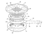
特に、この実施の形態のガスバーナ(33)は、図2に示すように、燃料ガス供給用のガスノズル(19)が差し込まれる上流端のガス入口(34)を備えたベンチュリ(36)と、該ベンチュリ(36)の下流端に連設され且つ内側空間(32)を有するように環状に形成されているバーナボディ(31)とから構成されており、前記ベンチュリ(36)内で、燃料ガスと一次空気が混合されて前記バーナボディ(31)に送られる。
The best mode for carrying out the present invention will be described below with reference to the accompanying drawings.
FIG. 1 is a schematic perspective view of a gas stove employed as the best mode for carrying out the present invention.
The top plate (1) of the casing (100) formed in the shape of a flat rectangular box has a burner opening (10), and the burner opening (10) is covered with a five-purpose cover (4). In addition, a gas burner (33) is disposed below the gas burner. Further, an operation knob (51) that is pushed in when the gas burner (33) is ignited and extinguished, and is rotated when adjusting the heating power, in the operation part (11) on the front surface of the casing (100), A combustion lamp (52) for notifying that the gas burner (33) is in a combustion state is provided.
In particular, the gas burner (33) of this embodiment comprises a venturi (36) having an upstream gas inlet (34) into which a gas nozzle (19) for fuel gas supply is inserted, as shown in FIG. A burner body (31) connected to the downstream end of the venturi (36) and formed in an annular shape so as to have an inner space (32) .In the venturi (36), fuel gas and Primary air is mixed and sent to the burner body (31).
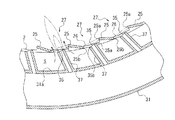
前記バーナボディ(31)の内側周面(31a)には、多数の縦長長方形状の筒状部(37)が前記内側空間(32)に向かって突出しており、前記筒状部(37)の軸線に沿って、貫通するように炎孔(35)が形成されている。すなわち、前記筒状部(37)の突出端に、前記炎孔(35)が開放する態様となっている。
そして、前記筒状部(37)の突出端で囲まれる前記内側空間(32)内に金属製のガイド筒(2)が収容される。言い換えれば、前記バーナボディ(31)の内側空間(32)内には、上記ガイド筒(2)が、筒状部(37)の突出幅に相当する隙間(S)をおいて収容される態様となる。
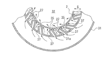
尚、前記筒状部(37)は、図3に示すように、内側空間(32)の中心に対して約20度傾斜させた姿勢で水平に突出するように設けられている。これにより、前記筒状部(37)に設けられた前記炎孔(35)からの燃焼ガスは、内側空間(32)の中心に向かって噴出されず、前記傾斜方向に向かって水平に噴出される。
On the inner peripheral surface (31a) of the burner body (31), a large number of vertically-long rectangular cylindrical portions (37) protrude toward the inner space (32), and the cylindrical portion (37) A flame hole (35) is formed so as to penetrate along the axis. That is, the flame hole (35) is opened at the projecting end of the cylindrical portion (37).
A metal guide tube (2) is housed in the inner space (32) surrounded by the protruding end of the tubular portion (37). In other words, the guide cylinder (2) is accommodated in the inner space (32) of the burner body (31) with a gap (S) corresponding to the protruding width of the cylindrical portion (37). It becomes.
Note that, as shown in FIG. 3, the cylindrical portion (37) is provided so as to protrude horizontally in a posture inclined about 20 degrees with respect to the center of the inner space (32). Thus, the combustion gas from the flame hole (35) provided in the cylindrical portion (37) is not ejected toward the center of the inner space (32), but is ejected horizontally in the inclined direction. The
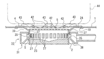
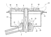
前記ガイド筒(2)は、図4に示すように、前記天板(1)に形成されたバーナ用開口(10)の周縁部に係止させるための上端フランジ(24)を具備していると共に、前記ガスバーナ(33)の筒状部(37)の突出端に対応する前記ガイド筒(2)の周壁の各位置には、前記突出端よりも一回り大きな縦長長方形状の窓部(27)が形成されている。
又、ガイド筒(2)の下端には、ガラスウールやセラミック等の断熱材(23)が嵌め込まれている。
そして、バーナ用開口(10)の周縁に係止させた前記上端フランジ(24)の上面に、赤熱プレート(5)を介して、五徳兼用カバー(4)を被蓋配設させて、ガスコンロが完成する。
As shown in FIG. 4, the guide tube (2) includes an upper end flange (24) for engaging with a peripheral edge of a burner opening (10) formed in the top plate (1). In addition, at each position of the peripheral wall of the guide tube (2) corresponding to the protruding end of the cylindrical portion (37) of the gas burner (33), a vertically elongated rectangular window portion (27 ) Is formed.
Further, a heat insulating material (23) such as glass wool or ceramic is fitted into the lower end of the guide tube (2).
Then, on the upper surface of the upper end flange (24) locked to the peripheral edge of the burner opening (10), the virtuosity cover (4) is covered with a red hot plate (5), and the gas stove is attached. Complete.
上記五徳兼用カバー(4)は、熱伝導性の良好な金属材料で形成されており、図2に示すように、中央部分に貫設された中央排気口(42)と、その外周域に、鍋(44)を載置させるための複数の鍋支持突起(43)が周方向に所定ピッチで放射状に配設されている。
又、バーナボディ(31)の下部内周は、図4の如く、下方に向かって直径が拡大する環状テーパー部(38)となっており、これにより、該環状テーパー部(38)に沿って二次空気が、前記バーナボディ(31)の内側周面(31a)とガイド筒(2)の外周面との間の隙間(S)へ導入させ易くなっている。尚、前記バーナボディ(31)の上方と天板(1)との間にも空間(39)が形成されており、前記環状テーパー部(38)及び空間(39)から、バーナボディ(31)とガイド筒(2)との隙間(S)に繋がる通路が、燃焼用の二次空気供給通路として機能する。
The virtually combined cover (4) is made of a metal material having good thermal conductivity. As shown in FIG. 2, the central exhaust port (42) penetrating through the central portion, A plurality of pan support protrusions (43) for placing the pan (44) are arranged radially at a predetermined pitch in the circumferential direction.
The lower inner periphery of the burner body (31) has an annular taper portion (38) whose diameter increases downward as shown in FIG. 4, and thereby, along the annular taper portion (38). Secondary air is easily introduced into the gap (S) between the inner peripheral surface (31a) of the burner body (31) and the outer peripheral surface of the guide tube (2). A space (39) is also formed between the burner body (31) and the top plate (1), and the burner body (31) is formed from the annular tapered portion (38) and the space (39). And the guide pipe (2) connected to the gap (S) functions as a secondary air supply passage for combustion.
次に、上記ガスコンロの使用の実際を説明する。
図1に表れる特定の操作つまみ(51)を押し込むと、点火装置(図示せず)が作動してガスバーナ(33)の炎孔(35)近傍に点火用スパークが連射される。
又、上記操作つまみ(51)が押し込まれると、ガスバーナ(33)へのガス回路に挿入されたガス弁が開弁してガスノズル(19)からベンチュリ(36)のガス入口(34)内に燃料ガスが噴出されると共に、噴出時のエゼクタ効果によって、ガスノズル(19)の周囲の空気が燃焼用一次空気としてガス入口(34)内に吸引され、これにより、一次空気が混合された燃焼ガスがガスバーナ(33)のバーナボディ(31)に送られ、筒状部(37)に設けられている炎孔(35)を通って内側空間(32)内に噴出する。
Next, the actual use of the gas stove will be described.
When a specific operation knob (51) shown in FIG. 1 is pushed in, an ignition device (not shown) is activated to ignite an ignition spark in the vicinity of the flame hole (35) of the gas burner (33).
When the operation knob (51) is pushed in, the gas valve inserted in the gas circuit to the gas burner (33) is opened, and the fuel from the gas nozzle (19) to the gas inlet (34) of the venturi (36) is opened. As the gas is ejected and the ejector effect at the time of ejection, the air around the gas nozzle (19) is sucked into the gas inlet (34) as the primary air for combustion, so that the combustion gas mixed with the primary air is It is sent to the burner body (31) of the gas burner (33), and jets into the inner space (32) through the flame hole (35) provided in the cylindrical part (37).
筒状部(37)は、上記したように傾斜姿勢にあることから、筒状部(37)の突出端の炎孔(35)から噴出される燃焼ガスは、前記内側空間(32)内に配設されているガイド筒(2)の窓部(27)を介して、前記ガイド筒(2)内に、図3の実線で示すように、中心よりも約20度の方向に向かって水平に噴き出す。これにより、前記燃焼ガスは、ガイド筒(2)内を旋回し、前記ガイド筒(2)内で燃焼ガスによる旋回流が生じる。
前記炎孔(35)から燃焼ガスが噴出すると、前記二次空気供給通路を通って、前記隙間(S)内に達した空気は、同図の二点鎖線で示すように、前記燃焼ガスによるエゼクタ効果により、前記窓部(27)を通って内側空間(32)に向かって吸引され、前記窓部(27)に対応する炎孔(35)からの燃焼ガスに対して二次空気として供給される。
尚、本実施の形態では、ガイド筒(2)内に形成される前記旋回流によって前記窓部(27)の内側近傍に負圧が発生することとなるから、二次空気は窓部(27)を通ってさらに円滑に吸引される。
Since the cylindrical portion (37) is in an inclined posture as described above, the combustion gas ejected from the flame hole (35) at the protruding end of the cylindrical portion (37) is in the inner space (32). As shown by the solid line in FIG. 3, the guide tube (2) is disposed horizontally through the window (27) of the guide tube (2) in the direction of about 20 degrees from the center. To erupt. Thereby, the combustion gas swirls in the guide cylinder (2), and a swirling flow is generated in the guide cylinder (2) by the combustion gas.
When the combustion gas is ejected from the flame hole (35), the air that has reached the gap (S) through the secondary air supply passage is caused by the combustion gas, as indicated by a two-dot chain line in FIG. Due to the ejector effect, the air is sucked toward the inner space (32) through the window (27) and supplied as secondary air to the combustion gas from the flame hole (35) corresponding to the window (27). Is done.
In the present embodiment, the swirl flow formed in the guide cylinder (2) generates a negative pressure in the vicinity of the inside of the window (27). ) Is more smoothly sucked through.
そして、二次空気が供給された燃焼ガスに、上記点火装置からの点火によってこれが燃焼し、筒状部(37)の突出端に燃焼炎が形成される。前記筒状部(37)は、上記したように、バーナボディ(31)の内側周面(31a)から中心方向に対して斜めに突出していることから、前記燃焼炎も、前記筒状部(37)の軸線に沿って斜めに噴出されることとなる。これにより、対向する燃焼炎の先端部相互が触れ合うことがなく、燃焼に悪影響が及ばない。又、隣り合う燃焼炎同士が接触し易くなり、相互に補炎の効果がある。 Then, the combustion gas supplied with the secondary air is combusted by ignition from the ignition device, and a combustion flame is formed at the protruding end of the cylindrical portion (37). As described above, the cylindrical portion (37) protrudes obliquely with respect to the central direction from the inner peripheral surface (31a) of the burner body (31). It will be ejected diagonally along the axis of 37). Thereby, the front-end | tip parts of the opposing combustion flame do not touch, and a bad influence is not exerted on combustion. In addition, adjacent combustion flames can easily come into contact with each other, and there is an effect of supplementing each other.
このときに生成される燃焼排気は、ガイド筒(2)内を旋回すると共に、中央で衝突しながら、ガイド筒(2)内を上昇する方向へ向きを変え、圧力を高め、前記赤熱プレート(5)を介して、五徳兼用カバー(4)の中央排気口(42)から吐出されて、鍋(44)が加熱される。
又、上記燃焼排気によって、五徳兼用カバー(4)の下方の赤熱プレート(5)が赤熱され、該赤熱プレート(5)からの輻射熱が五徳兼用カバー(4)越しに鍋(44)に照射されることとなるから、前記輻射熱によっても鍋(44)が加熱される。
The combustion exhaust generated at this time turns in the guide cylinder (2) and changes the direction in the direction of rising in the guide cylinder (2) while colliding in the center, increasing the pressure, and the red hot plate ( The pan (44) is heated by being discharged from the central exhaust port (42) of the virtually combined cover (4) through 5).
Also, by the combustion exhaust, the red hot plate (5) below the virtuosity cover (4) is red hot, and the radiant heat from the red hot plate (5) is irradiated to the pan (44) through the virtuosity cover (4). Therefore, the pan (44) is also heated by the radiant heat.
一方、ガスバーナ(33)の燃焼時にはガイド筒(2)が高温になるが、前記ガイド筒(2)の底部には断熱材(23)が嵌め込まれているから、ガイド筒(2)内の熱がケーシング(100)内に漏れ難くなり、これにより、ケーシング(100)内に配設された電気制御装置等への熱的悪影響を防止することができる。 On the other hand, when the gas burner (33) burns, the guide cylinder (2) becomes hot, but since the heat insulating material (23) is fitted into the bottom of the guide cylinder (2), the heat in the guide cylinder (2) is Is less likely to leak into the casing (100), thereby preventing adverse thermal effects on the electric control device and the like disposed in the casing (100).
又、図5は、ガイド筒(2)の窓部(27)の変形例を示している。
このものでは、隣り合う窓部(27)(27)相互間の仕切壁(25)(25)の一方の側縁(25a)がガイド筒(2)内へ突出するように、前記仕切壁(25)をガイド筒(2)の周面に対して傾斜させる構成としたもので、これにより、一つの仕切壁(25)の前記一方の側縁(25a)と、窓部(27)を介して隣り合う他の仕切壁(25)の他方の側縁(25b)との間に形成される前記窓部(27)の開口面(26)が、同図の二点鎖線で示すように、前記ガイド筒(2)の前記周面に対して傾斜する態様となる。
FIG. 5 shows a modification of the window portion (27) of the guide tube (2).
In this, the partition wall (27), the partition wall (27) so that one side edge (25a) of the partition wall (25) between the window portions (25) protrudes into the guide tube (2) ( 25) is inclined with respect to the peripheral surface of the guide tube (2), and thereby, through the one side edge (25a) of one partition wall (25) and the window portion (27). The opening surface (26) of the window part (27) formed between the other side wall (25b) of the other partition wall (25) adjacent to each other as shown by the two-dot chain line in FIG. The guide cylinder (2) is inclined with respect to the peripheral surface.
前記仕切壁(25)の傾斜角度は、前記窓部(27)の開口面(26)が、上記したように斜めに突出させた筒状部(37)の軸線方向に対して略垂直に位置するように設定されている。これにより、前記筒状部(37)の軸線方向に沿って形成されている炎孔(35)から噴出される燃焼ガスの噴出方向に対しても前記開口面(26)は略垂直に対向することとなり、一つの窓部(27)内において、前記一方の側縁(25a)から炎孔(35)の一方の側縁(35a)までの距離と、前記他方の側縁(25b)から前記炎孔(35)の他方の側縁(35b)までの距離は、ほぼ同一となる。 The inclination angle of the partition wall (25) is such that the opening surface (26) of the window portion (27) is positioned substantially perpendicular to the axial direction of the cylindrical portion (37) projecting obliquely as described above. It is set to be. As a result, the opening surface (26) also faces substantially perpendicularly to the direction in which the combustion gas is ejected from the flame hole (35) formed along the axial direction of the cylindrical portion (37). In one window portion (27), the distance from the one side edge (25a) to one side edge (35a) of the flame hole (35), and the other side edge (25b) to the above-mentioned The distance to the other side edge (35b) of the flame hole (35) is substantially the same.
上記構成とすることにより、前記二次空気供給通路を通って、前記バーナボディ(31)の内側周面(31a)と前記ガイド筒(2)との隙間(S)に到達した二次空気が、前記炎孔(35)からガイド筒(2)内に噴出される燃焼ガスに供給されるまでの距離が、前記筒状部(37)の左右両側方において等しくなり、前記二次空気は、前記筒状部(37)の突出端の両側方から略均等な吸引力で前記窓部(27)を通ってガイド筒(2)内に吸引されることとなる。よって、燃焼用二次空気を略均等の吸引力でガイド筒内に吸引することができるから、前記燃焼ガスの燃焼が良好になる。 With the above configuration, the secondary air that has reached the gap (S) between the inner peripheral surface (31a) of the burner body (31) and the guide tube (2) through the secondary air supply passage is formed. The distance from the flame hole (35) to the combustion gas jetted into the guide cylinder (2) is equal on both the left and right sides of the cylindrical part (37), and the secondary air is From the both sides of the projecting end of the cylindrical part (37), it is sucked into the guide cylinder (2) through the window part (27) with a substantially equal suction force. Therefore, the combustion secondary air can be sucked into the guide cylinder with a substantially uniform suction force, so that combustion of the combustion gas becomes good.
尚、上記各実施の形態では、ガイド筒(2)の窓部(27)を、前記筒状部(37)に設けた炎孔(35)にそれぞれ対応するように、前記炎孔(35)と同じ数だけ設けたが、複数の隣り合う窓部(27)相互を連続させて、帯状の窓部(27)を形成しても良い。この場合、一つの窓部(27)に複数の筒状部(37)の突出端が対応することとなる。
又、上記実施の形態ではバーナ用開口(10)を五徳兼用カバー(4)で覆ったが、天板(1)上のバーナ用開口(10)の外周域に五徳を載置するガスコンロとしても良い。
尚、上記実施の形態では、炎孔(35)の向きを中心方向に対して斜めにしたが、中心に向けても良い。又、上記実施の形態では、炎孔(35)の向きを水平としたが、斜め上方としても良い。
In each of the above embodiments, the flame hole (35) is formed so that the window part (27) of the guide cylinder (2) corresponds to the flame hole (35) provided in the cylindrical part (37), respectively. However, a plurality of adjacent window portions (27) may be continuous to form a strip-shaped window portion (27). In this case, the protruding ends of the plurality of cylindrical portions (37) correspond to one window portion (27).
In the above embodiment, the burner opening (10) is covered with the virtuosity cover (4), but the gas stove on which the virtues are placed on the outer peripheral area of the burner opening (10) on the top plate (1) can be used. good.
In the above embodiment, the direction of the flame hole (35) is oblique with respect to the central direction, but it may be directed toward the center. In the above embodiment, the direction of the flame hole (35) is horizontal, but it may be obliquely upward.
(2) ・・・・・・ガイド筒
(27)・・・・・・窓部
(31)・・・・・・バーナボディ
(32)・・・・・・内側空間
(33)・・・・・・ガスバーナ
(37)・・・・・・炎孔部
(S) ・・・・・・隙間
(2) ・ ・ ・ ・ ・ ・ Guide tube
(27) ... Window
(31) ... Burner body
(32) ... Inside space
(33) ... Gas burner
(37) ... flame hole
(S) ・ ・ ・ ・ ・ ・ Gap
Claims (5)
前記ガスバーナは、環状に構成されたバーナボディを具備し、
前記バーナボディの内側周面で包囲された内側空間内にそれよりも小径のガイド筒が収容され、
前記バーナボディの前記内側周面に複数の炎孔が開設されると共に、前記炎孔に対応する前記ガイド筒の各位置に窓部が開設され、
前記バーナボディの上方又は下方から前記バーナボディと前記ガイド筒との隙間に連通する二次空気供給通路が設けられていることを特徴とする燃焼機器。 In combustion equipment equipped with a gas burner,
The gas burner comprises a burner body configured in an annular shape,
A guide cylinder having a smaller diameter is accommodated in the inner space surrounded by the inner peripheral surface of the burner body,
A plurality of flame holes are opened on the inner peripheral surface of the burner body, and a window is opened at each position of the guide cylinder corresponding to the flame holes,
A combustion apparatus, wherein a secondary air supply passage communicating with a gap between the burner body and the guide cylinder from above or below the burner body is provided.
前記バーナボディの前記内側周面に、前記内側空間の中心に対して所定角度傾斜させた状態で突出する複数の筒状部が設けられ、
前記炎孔は、前記筒状部の軸線に沿って貫通形成されており、
前記ガイド筒は、全ての前記筒状部の突出端で包囲される範囲に収容されると共に、前記窓部は、前記突出端が対応する各位置に形成されていることを特徴とする燃焼機器。 The combustion device according to claim 1,
On the inner peripheral surface of the burner body, there are provided a plurality of cylindrical portions protruding in a state inclined at a predetermined angle with respect to the center of the inner space,
The flame hole is formed penetrating along the axis of the cylindrical portion,
The guide cylinder is accommodated in a range surrounded by the protruding ends of all the cylindrical portions, and the window portion is formed at each position corresponding to the protruding ends. .
前記窓部の左右両側縁を含む開口面が前記筒状部の軸線方向と略垂直に位置するように、前記開口面を前記ガイド筒の周面に対して所定角度傾斜させたことを特徴とする燃焼機器。 The combustion device according to claim 2,
The opening surface is inclined at a predetermined angle with respect to the peripheral surface of the guide tube so that the opening surface including the left and right side edges of the window portion is positioned substantially perpendicular to the axial direction of the cylindrical portion. Burning equipment.
前記燃焼機器は、天板にバーナ用開口が開設され、前記バーナ用開口の下方に前記バーナボディが配設され、前記バーナボディに設けられた複数の前記炎孔から噴出する燃焼ガスの燃焼によって生成される燃焼排気を前記バーナ用開口から排出させると共に、前記燃焼排気で鍋底を加熱させる形式のガスコンロである燃焼機器。 The combustion device according to any one of claims 1 to 3,
In the combustion device, a burner opening is formed in the top plate, the burner body is disposed below the burner opening, and combustion of the combustion gas ejected from the plurality of flame holes provided in the burner body is performed. Combustion equipment which is a gas stove of a type in which the generated combustion exhaust is discharged from the burner opening and the bottom of the pan is heated by the combustion exhaust.
前記バーナ用開口は、上面に複数の鍋支持用突起が備えられ且つ前記鍋支持用突起の形成域よりも内側の中央部分に排気孔が貫通形成されている五徳兼用カバーで被覆されていることを特徴とする燃焼機器。
The combustion device according to claim 4,
The burner opening is covered with a virtuosity cover that has a plurality of pan support projections on the upper surface and has an exhaust hole penetrating through the central portion inside the formation region of the pan support projections. Combustion equipment characterized by.
Priority Applications (1)
| Application Number | Priority Date | Filing Date | Title |
|---|---|---|---|
| JP2004110715A JP2005291666A (en) | 2004-04-05 | 2004-04-05 | Combustion apparatus |
Applications Claiming Priority (1)
| Application Number | Priority Date | Filing Date | Title |
|---|---|---|---|
| JP2004110715A JP2005291666A (en) | 2004-04-05 | 2004-04-05 | Combustion apparatus |
Publications (1)
| Publication Number | Publication Date |
|---|---|
| JP2005291666A true JP2005291666A (en) | 2005-10-20 |
Family
ID=35324784
Family Applications (1)
| Application Number | Title | Priority Date | Filing Date |
|---|---|---|---|
| JP2004110715A Pending JP2005291666A (en) | 2004-04-05 | 2004-04-05 | Combustion apparatus |
Country Status (1)
| Country | Link |
|---|---|
| JP (1) | JP2005291666A (en) |
Cited By (4)
| Publication number | Priority date | Publication date | Assignee | Title |
|---|---|---|---|---|
| JP2009186152A (en) * | 2008-02-08 | 2009-08-20 | Paloma Ind Ltd | Cooker |
| KR101835673B1 (en) | 2016-12-23 | 2018-03-07 | 정현각 | Electronic mat assembly for roast |
| CN110345479A (en) * | 2019-07-12 | 2019-10-18 | 宁波方太厨具有限公司 | Fire cover for kitchen range |
| CN110887075A (en) * | 2018-09-09 | 2020-03-17 | 宁波方太厨具有限公司 | Energy-gathering cover for stove and gas stove applying same |
-
2004
- 2004-04-05 JP JP2004110715A patent/JP2005291666A/en active Pending
Cited By (4)
| Publication number | Priority date | Publication date | Assignee | Title |
|---|---|---|---|---|
| JP2009186152A (en) * | 2008-02-08 | 2009-08-20 | Paloma Ind Ltd | Cooker |
| KR101835673B1 (en) | 2016-12-23 | 2018-03-07 | 정현각 | Electronic mat assembly for roast |
| CN110887075A (en) * | 2018-09-09 | 2020-03-17 | 宁波方太厨具有限公司 | Energy-gathering cover for stove and gas stove applying same |
| CN110345479A (en) * | 2019-07-12 | 2019-10-18 | 宁波方太厨具有限公司 | Fire cover for kitchen range |
Similar Documents
| Publication | Publication Date | Title |
|---|---|---|
| KR20140137721A (en) | Double burner type gas burner | |
| KR101064050B1 (en) | Burner assembly and cooking apparatus including the same | |
| JP5234575B2 (en) | Stove burner | |
| JP2005291666A (en) | Combustion apparatus | |
| JP6842957B2 (en) | Stove | |
| KR20120103302A (en) | Burner and cooking appliance comprising the same | |
| JP4203456B2 (en) | Stove burner | |
| KR100938201B1 (en) | Burner and cooking appliance comprising the same | |
| KR100738697B1 (en) | Shielded double burner | |
| KR101946722B1 (en) | Ignition device for gas burner that can be completely burned | |
| KR101596497B1 (en) | Top burners and cooking utensils containing them | |
| KR101531057B1 (en) | Top burners and cooking utensils containing them | |
| KR20070053914A (en) | Shielded double burner | |
| JP2005233497A (en) | Gas range | |
| JP4085047B2 (en) | Gas stove | |
| EP4686872A1 (en) | Burner, gas cooker, and integrated electrical appliance | |
| JP2005291667A (en) | Gas cookstove | |
| KR100786072B1 (en) | Gas copy cooker | |
| JP4338195B2 (en) | Stove | |
| JP2005207668A (en) | Gas cooking stove | |
| KR101400687B1 (en) | Gun type oil burner | |
| JPH07293837A (en) | Nozzle mixing gas burner with pilot burner | |
| KR101232006B1 (en) | Sealed double burner | |
| JP2781926B2 (en) | NOx reduction burner | |
| JP2005257185A (en) | Gas stove |